Incremental optical scale GVS 200 - Willtec
4
Incremental optical scale GVS 200 Willtec Messtechnik ek, Eschenweg 4, 79232 March-Hugstetten, Fon:07665/93465-0 Fax:07665/93465-22 [email protected] www.willtec.de Page 1 of 4 Characteristics • Optical scale with glass measuring support (grating pitch 20 μm) • Particularly suitable for synchronized press brakes • Reader head guided by a self-aligned and self-cleaning sliding carriage with spring system • Resolutions up to 0.1 μm; accuracy grade up to ± 1 μm • Adjustable cable output • Reference indexes at coded distance or selectable every 10 mm along the entire measuring length, with Zero Magneto Set device • The adjustable cable output and the selectable zero references make the scale SYMMETRIC and applicable, in the same version, to both columns of the press brake • Various possibilities of application, with double-effect joint or steel wire • Option: safety limit switches, positionable at both ends Mechanical and electrical characteristics Mechanical Electrical • Rugged and heavy PROFILE, made of anodized aluminium. Dimensions 55x28 mm. • Elastic COUPLING for misalignment compensation and self-correction of mechanical hysteresis. Backlash error <0.2 μm. • SEALING LIPS for the protection of the grating, made of special elastomer resistant to oil and wearing. Special self-blocking profile. • READER HEAD, consisting of tie rod and reading block, with fully protected place for electronic boards. • CARRIAGE guided by ball bearings with gothic arch profile sliding on tempered and grinded guides, to guarantee the system accuracy and the absence of wearing. • Die-cast TIE ROD, with nickel-plating surface treatment. • GLASS SCALE placed in the scale housing. • Elastomeric GASKETS which allow to reproduce the full protection in mechanical joints (in case of disassembling). • Adjustable CABLE output. • Various possibilities of application, with double-effect joint or steel wire. GV-PB adapter guarantees the compatibility with scale mod. PBS-HR. • Full possibility to disassemble and reassemble the scale. • Possibility of direct service. • Reading device with an infra-red light emitter and receiving photodiodes. • A and B output signals with phase displacement of 90° (electrical). • Reference indexes at coded distance or selectable every 10 mm. • CABLE: - 8-wire shielded cable Ø= 6.1 mm, PUR external sheath. - Conductors section: power supply 0.35 mm²; signals 0.14 mm². The cable’s bending radius should not be lower than 80 mm. The cable is suitable for continuous movements. line driver push-pull Conductor colour +V +V red 0 V 0 V dark blue A B green A NC orange B A white B NC light-blue I 0 I 0 brown Io NC yellow SCH SCH shield
Transcript of Incremental optical scale GVS 200 - Willtec
Incremental optical scale GVS 200
Willtec Messtechnik ek, Eschenweg 4, 79232 March-Hugstetten, Fon:07665/93465-0 Fax:07665/93465-22 [email protected] www.willtec.de Page 1 of 4
Characteristics
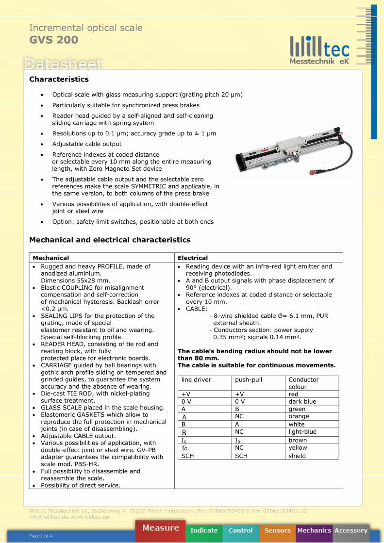
• Optical scale with glass measuring support (grating pitch 20 μm)
• Particularly suitable for synchronized press brakes
• Reader head guided by a self-aligned and self-cleaning sliding carriage with spring system
• Resolutions up to 0.1 μm; accuracy grade up to ± 1 μm
• Adjustable cable output
• Reference indexes at coded distance or selectable every 10 mm along the entire measuring length, with Zero Magneto Set device
• The adjustable cable output and the selectable zero references make the scale SYMMETRIC and applicable, in the same version, to both columns of the press brake
• Various possibilities of application, with double-effect joint or steel wire
• Option: safety limit switches, positionable at both ends
Mechanical and electrical characteristics Mechanical Electrical • Rugged and heavy PROFILE, made of
anodized aluminium. Dimensions 55x28 mm.
• Elastic COUPLING for misalignment compensation and self-correction of mechanical hysteresis. Backlash error <0.2 μm.
• SEALING LIPS for the protection of the grating, made of special elastomer resistant to oil and wearing. Special self-blocking profile.
• READER HEAD, consisting of tie rod and reading block, with fully protected place for electronic boards.
• CARRIAGE guided by ball bearings with gothic arch profile sliding on tempered and grinded guides, to guarantee the system accuracy and the absence of wearing.
• Die-cast TIE ROD, with nickel-plating surface treatment.
• GLASS SCALE placed in the scale housing. • Elastomeric GASKETS which allow to
reproduce the full protection in mechanical joints (in case of disassembling).
• Adjustable CABLE output. • Various possibilities of application, with
double-effect joint or steel wire. GV-PB adapter guarantees the compatibility with scale mod. PBS-HR.
• Full possibility to disassemble and reassemble the scale.
• Possibility of direct service.
• Reading device with an infra-red light emitter and receiving photodiodes.
• A and B output signals with phase displacement of 90° (electrical).
• Reference indexes at coded distance or selectable every 10 mm.
• CABLE: - 8-wire shielded cable Ø= 6.1 mm, PUR external sheath. - Conductors section: power supply 0.35 mm²; signals 0.14 mm².
The cable’s bending radius should not be lower than 80 mm. The cable is suitable for continuous movements. line driver push-pull Conductor
colour +V +V red 0 V 0 V dark blue A B green A NC orange B A white B NC light-blue I0 I0 brown Io NC yellow SCH SCH shield
Incremental optical scale GVS 200
Willtec Messtechnik ek, Eschenweg 4, 79232 March-Hugstetten, Fon:07665/93465-0 Fax:07665/93465-22 [email protected] www.willtec.de Page 2 of 4
* With a 0,1 resolution, the maximum traversing speed becomes 40 m/min ** Pressurization set up on request *** Ensuring the required power supply voltage to the transducer, the maximum cable length can be
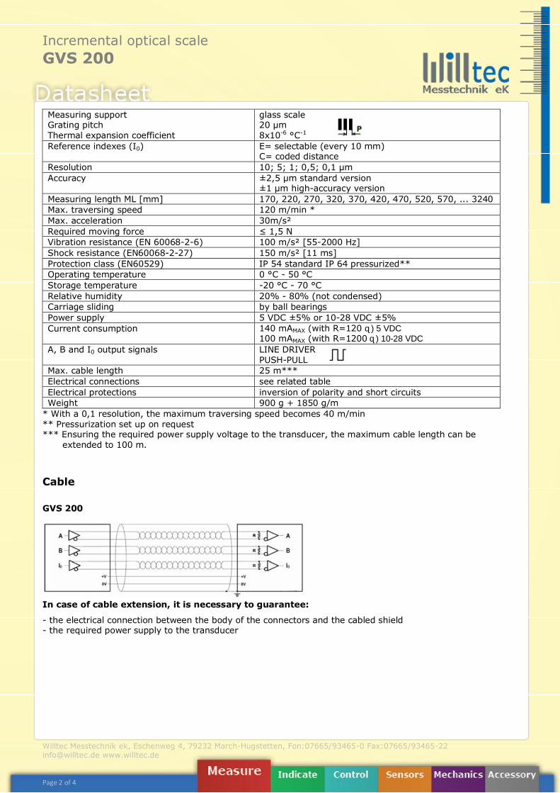
extended to 100 m. Cable
GVS 200 In case of cable extension, it is necessary to guarantee:
- the electrical connection between the body of the connectors and the cabled shield - the required power supply to the transducer
Measuring support Grating pitch Thermal expansion coefficient
glass scale 20 µm 8x10⁻⁶ °C-1
Reference indexes (I0) E= selectable (every 10 mm) C= coded distance
Resolution 10; 5; 1; 0,5; 0,1 µm Accuracy ±2,5 µm standard version
±1 µm high-accuracy version Measuring length ML [mm] 170, 220, 270, 320, 370, 420, 470, 520, 570, ... 3240 Max. traversing speed 120 m/min * Max. acceleration 30m/s² Required moving force ≤ 1,5 N Vibration resistance (EN 60068-2-6) 100 m/s² [55-2000 Hz] Shock resistance (EN60068-2-27) 150 m/s² [11 ms] Protection class (EN60529) IP 54 standard IP 64 pressurized** Operating temperature 0 °C - 50 °C Storage temperature -20 °C - 70 °C Relative humidity 20% - 80% (not condensed) Carriage sliding by ball bearings Power supply 5 VDC ±5% or 10-28 VDC ±5% Current consumption 140 mAMAX (with R=120 Ω) 5 VDC
100 mAMAX (with R=1200 Ω) 10-28 VDC A, B and I0 output signals LINE DRIVER
PUSH-PULL Max. cable length 25 m*** Electrical connections see related table Electrical protections inversion of polarity and short circuits Weight 900 g + 1850 g/m
Incremental optical scale GVS 200
Willtec Messtechnik ek, Eschenweg 4, 79232 March-Hugstetten, Fon:07665/93465-0 Fax:07665/93465-22 [email protected] www.willtec.de Page 3 of 4
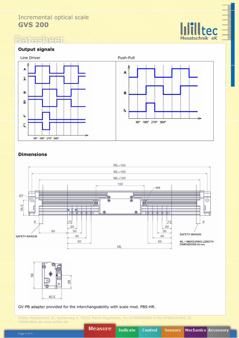
Output signals
Line Driver Push-Pull
Dimensions
GV-PB adapter provided for the interchangeability with scale mod. PBS-HR.
Incremental optical scale GVS 200
Willtec Messtechnik ek, Eschenweg 4, 79232 March-Hugstetten, Fon:07665/93465-0 Fax:07665/93465-22 [email protected] www.willtec.de Page 4 of 4
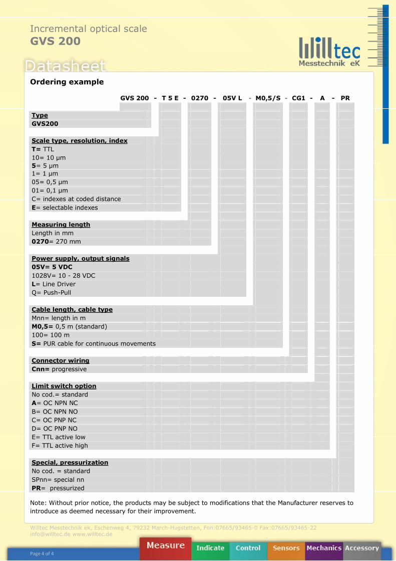
Ordering example
Note: Without prior notice, the products may be subject to modifications that the Manufacturer reserves to introduce as deemed necessary for their improvement.
GVS 200 - T 5 E - 0270 - 05V L - M0,5/S - CG1 - A - PR Type GVS200 Scale type, resolution, index T= TTL 10= 10 µm 5= 5 µm 1= 1 µm 05= 0,5 µm 01= 0,1 µm C= indexes at coded distance E= selectable indexes Measuring length Length in mm 0270= 270 mm Power supply, output signals 05V= 5 VDC 1028V= 10 - 28 VDC L= Line Driver Q= Push-Pull Cable length, cable type Mnn= length in m M0,5= 0,5 m (standard) 100= 100 m S= PUR cable for continuous movements Connector wiring Cnn= progressive Limit switch option No cod.= standard A= OC NPN NC B= OC NPN NO C= OC PNP NC D= OC PNP NO E= TTL active low F= TTL active high Special, pressurization No cod. = standard SPnn= special nn PR= pressurized