III. Determination of Crystal Structurelehre.ikz-berlin.de › physhu ›...
52
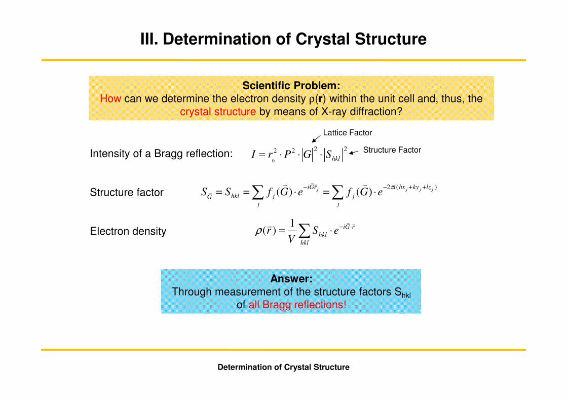
III. Determination of Crystal Structure Intensity of a Bragg reflection: Structure factor Electron density 2 2 2 2 0 hkl S G P r I ⋅ ⋅ ⋅ = ) ( 2 ) ( ) ( j j j j lz ky hx i j j r G i j j hkl G e G f e G f S S + + - - ⋅ = ⋅ = = ∑ ∑ π v v v v v ∑ ⋅ - ⋅ = hkl r G i hkl e S V r v v v 1 ) ( ρ Scientific Problem: How can we determine the electron density ρ(r) within the unit cell and, thus, the crystal structure by means of X-ray diffraction? Answer: Through measurement of the structure factors S hkl of all Bragg reflections! Determination of Crystal Structure Lattice Factor Structure Factor
Transcript of III. Determination of Crystal Structurelehre.ikz-berlin.de › physhu ›...
III. Determination of Crystal Structure
Intensity of a Bragg reflection:
Structure factor
Electron density
2222
0 hklSGPrI ⋅⋅⋅=
)(2)()( jjjj lzkyhxi
j
j
rGi
j
jhklGeGfeGfSS
++−−⋅=⋅== ∑∑
πvv vv
v
∑ ⋅−⋅=hkl
rGi
hkl eSV
rvvv 1
)(ρ
Scientific Problem: How can we determine the electron density ρ(r) within the unit cell and, thus, the
crystal structure by means of X-ray diffraction?
Answer: Through measurement of the structure factors Shkl
of all Bragg reflections!
Determination of Crystal Structure
Lattice Factor
Structure Factor
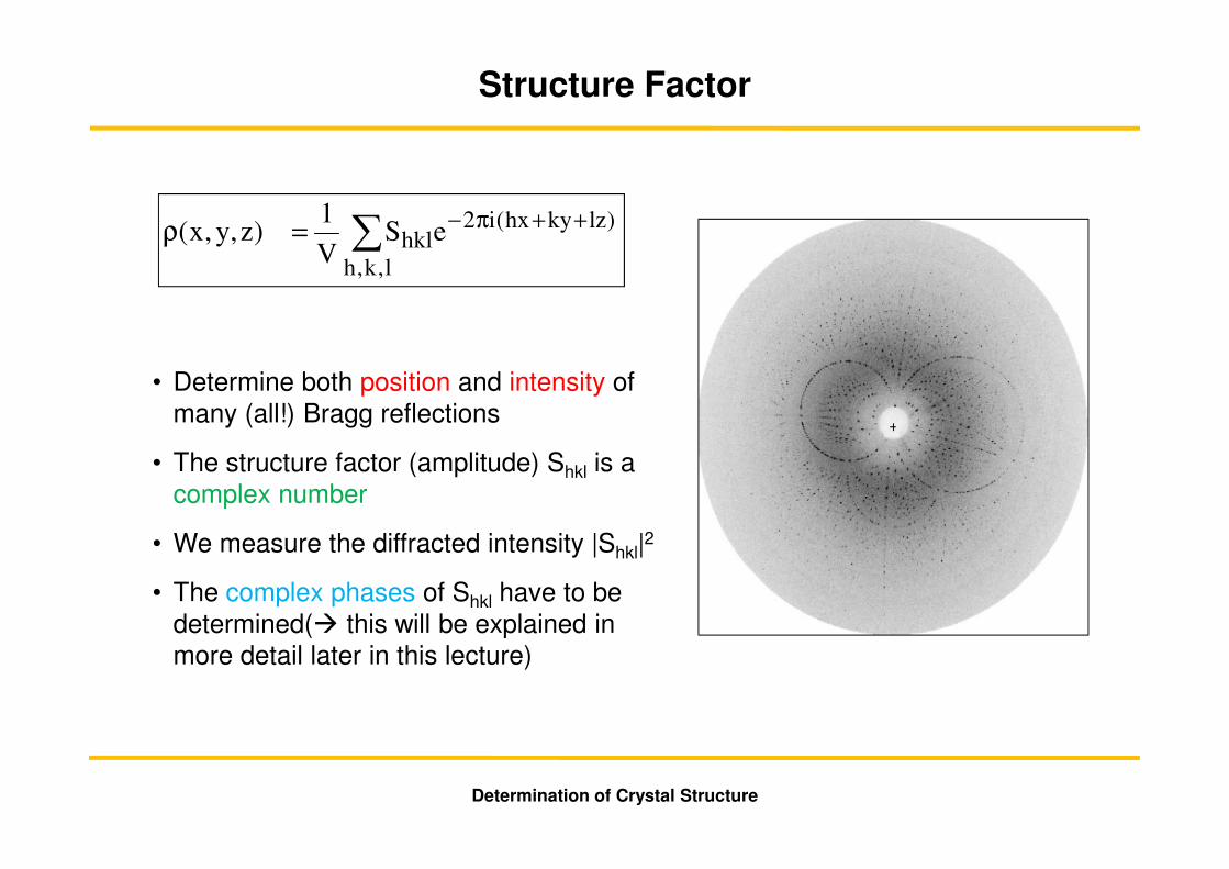
• Determine both position and intensity of many (all!) Bragg reflections
• The structure factor (amplitude) Shkl is a complex number
• We measure the diffracted intensity |Shkl|2
• The complex phases of Shkl have to be determined(� this will be explained in more detail later in this lecture)
∑ ++π−=ρ
l,k,h
)lzkyhx(i2hkleS
V
1)z,y,x(
Structure Factor
Determination of Crystal Structure
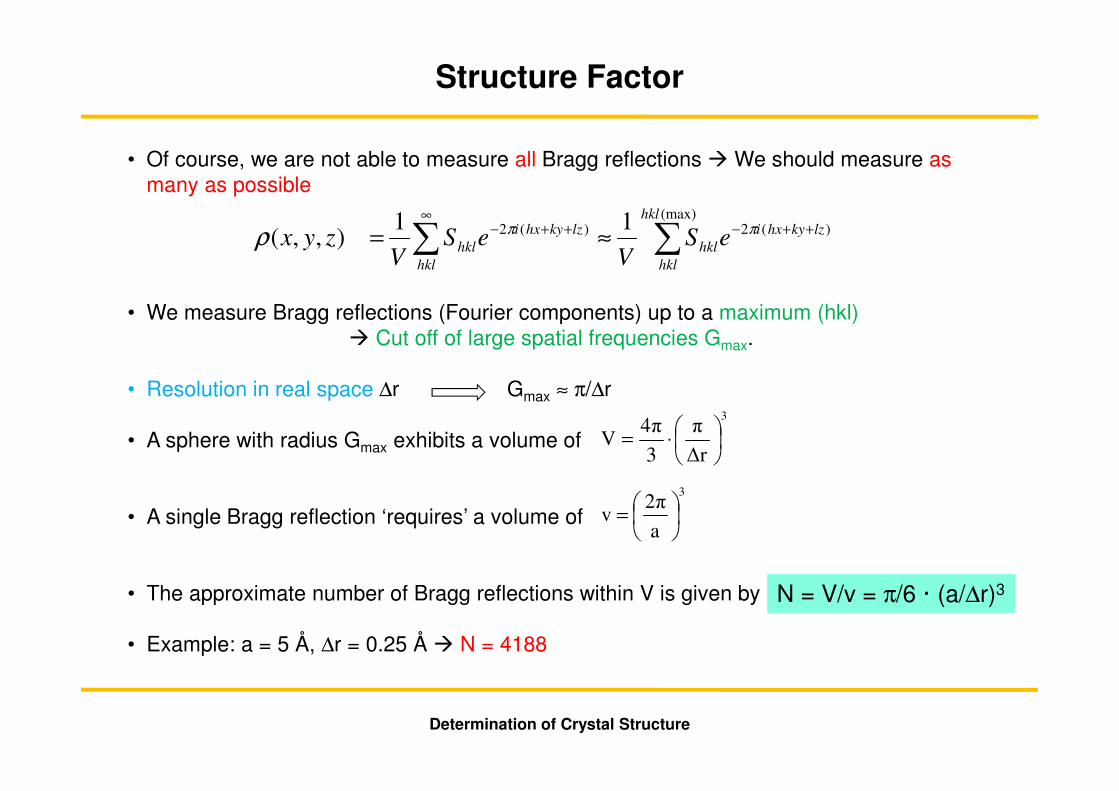
• Of course, we are not able to measure all Bragg reflections � We should measure as many as possible
• We measure Bragg reflections (Fourier components) up to a maximum (hkl) � Cut off of large spatial frequencies Gmax.
• Resolution in real space ∆r Gmax ≈ π/∆r
• A sphere with radius Gmax exhibits a volume of
• A single Bragg reflection ‘requires’ a volume of
• The approximate number of Bragg reflections within V is given by
• Example: a = 5 Å, ∆r = 0.25 Å � N = 4188
3
∆r
π
3
4πV
⋅=
3
a
2πv
=
N = V/v = π/6 · (a/∆r)3
∑∑ ++−∞
++− ≈=(max)
)(2)(2 11),,(
hkl
hkl
lzkyhxi
hkl
hkl
lzkyhxi
hkl eSV
eSV
zyxππρ
Determination of Crystal Structure
Structure Factor

Ewald Sphere and Ewald Construction
if kkGvvv
−=
• |ki| = |kf| = k = 2π/λ
• Multitude of all possible incoming and outgoing directions of the x-ray beam defines a sphere with radius r = k = 2π/λ Ewald Sphere
• The origin of the incoming wave vector ki represents the center of the Ewald Sphere
• The head of the incoming wave vector ki is the origin of reciprocal space
ki
Ghkl000
Determination of Crystal Structure

• If surface of Ewald Sphere comprises a reciprocal lattice point Bragg condition is fulfilled
• Limiting sphere (in German: “Ausbreitungskugel”) contains achievable reciprocal lattice points at a given X-ray wavelength
• Radius of limiting sphere: r = 2k = 4π/λ
• Number of Bragg reflections within sphere:
• We can reach eight times more Bragg reflections when the wavelength is reduced by a factor of two
• a = 5 Å, λ = 0.7 Å, N = 12000
( )( ) 3
3
3
3
3
32
2
4
3
4
λπ
π
λππ a
aN ⋅=≈
Determination of Crystal Structure
Ewald Sphere and Ewald Construction
Limiting Sphere
Diffracted Wave
Incoming Wave
Ewald Sphere
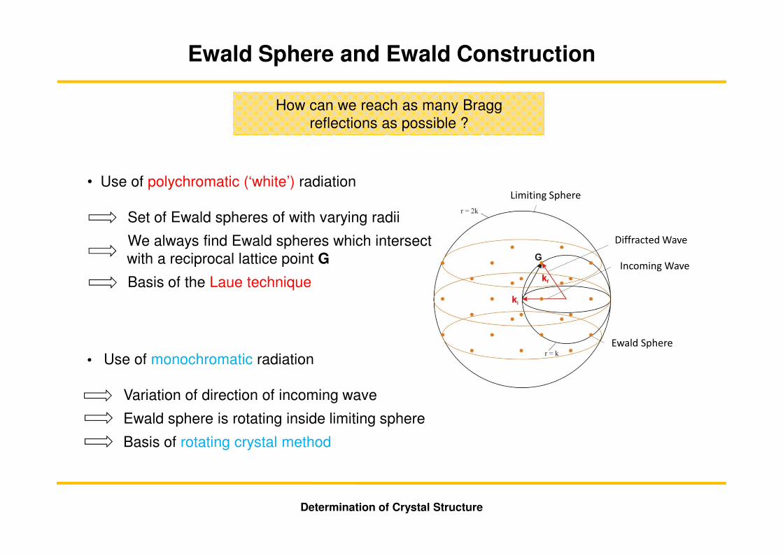
How can we reach as many Bragg reflections as possible ?
• Use of polychromatic (‘white’) radiation
Set of Ewald spheres of with varying radii
We always find Ewald spheres which intersect with a reciprocal lattice point G
Basis of the Laue technique
• Use of monochromatic radiation
Variation of direction of incoming wave
Ewald sphere is rotating inside limiting sphere
Basis of rotating crystal method
Determination of Crystal Structure
Ewald Sphere and Ewald Construction
Limiting Sphere
Diffracted Wave
Incoming Wave
Ewald Sphere

Reflections
Net Planes Crystal
Beam Stop
Film/Detector
Collimated
Polychromatic
Incoming Beam
The Laue Technique
• Oldest (1912)• Simplest Technique
Experimental setup for X-Ray diffraction W. Friedrich, P. Knipping und Max von Laue, 1912,
Deutsches Museum
• Each net plane is selecting the suitable x-ray wavelength for which the Bragg condition is fulfilled.
• The angle of the diffracted beam relative to theincoming beam is then two times the Bragg angle(which is the angle of the incoming beam relative tothe net plane).
Determination of Crystal Structure
1 001
11 02
reciprocal directions
Simulation
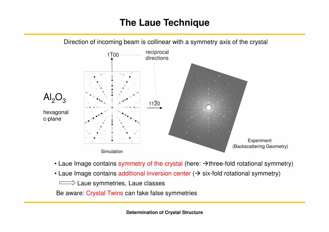
Direction of incoming beam is collinear with a symmetry axis of the crystal
• Laue Image contains symmetry of the crystal (here: �three-fold rotational symmetry)
• Laue Image contains additional inversion center (� six-fold rotational symmetry)
Laue symmetries, Laue classes
Be aware: Crystal Twins can fake false symmetries
Al2O3
hexagonal c-plane
Experiment(Backscattering Geometry)
Determination of Crystal Structure
The Laue Technique
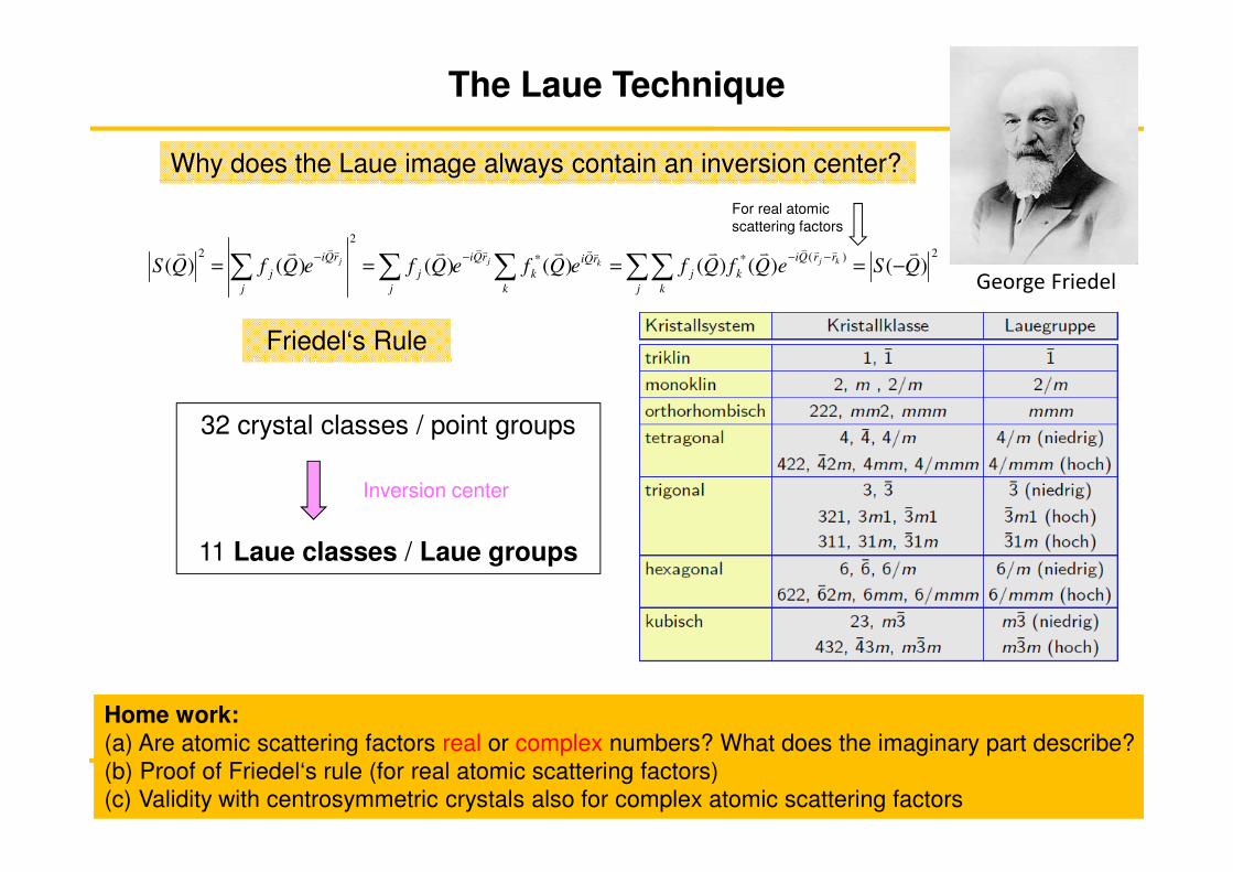
Why does the Laue image always contain an inversion center?
2)(**
2
2
)()()()()()()( QSeQfQfeQfeQfeQfQS kjkjj rrQi
k
j k
j
rQi
k
k
rQi
j
j
rQi
j
j
vvvvvvv vvvvvvvvv
−====−−−−
∑∑∑∑∑
Friedel‘s Rule
32 crystal classes / point groups
Inversion center
11 Laue classes / Laue groups
George Friedel
For real atomic scattering factors
Determination of Crystal Structure
The Laue Technique
Home work: (a) Are atomic scattering factors real or complex numbers? What does the imaginary part describe? (b) Proof of Friedel‘s rule (for real atomic scattering factors)(c) Validity with centrosymmetric crystals also for complex atomic scattering factors
Kristallstrukturbestimmung
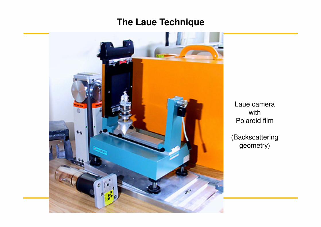
Laue camera with
Polaroid film
(Backscattering geometry)
The Laue Technique

Limitations of Laue technique for home lab X-ray sources
• Complex spectral distribution from X-ray tube
� characteristic lines (these wavelengths should be avoided)
� modification of Bremsstrahlung through absorption inside anode
� normalization of intensity is very difficult
• Application of Laue technique for crystal orientation
Renaissance of Laue technique at synchrotron radiation facilites
• continuous and predictable emission spectrum
• high photon flux, small divergence (� high brilliance)
Advantages: � fast (�biological systems)
� time resolved (< 50 ps)
� use of area detectors (Image-Plates, CCD, CMOS)
Drawbacks:� each Bragg reflection is created by a different X-ray wavelength (Assignment !)
� problems with higher harmonics (e.g. 002 (λ) und 004 (λ/2) appear at the same position on the detector)
Determination of Crystal Structure
The Laue Technique
Limiting Sphere
Diffracted Wave
Incoming Wave
Ewald Sphere
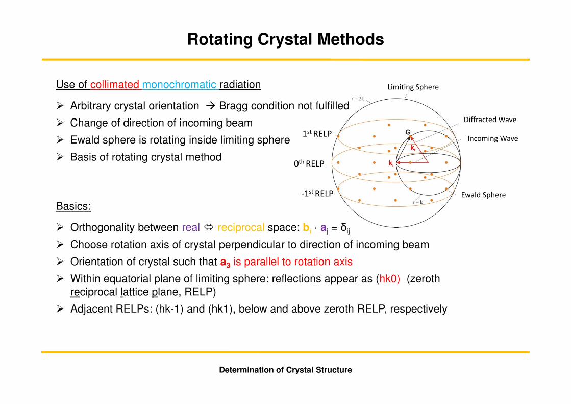
Rotating Crystal Methods
Use of collimated monochromatic radiation
� Arbitrary crystal orientation � Bragg condition not fulfilled
� Change of direction of incoming beam
� Ewald sphere is rotating inside limiting sphere
� Basis of rotating crystal method
Basics:
� Orthogonality between real � reciprocal space: bi · aj = δij
� Choose rotation axis of crystal perpendicular to direction of incoming beam
� Orientation of crystal such that a3 is parallel to rotation axis
� Within equatorial plane of limiting sphere: reflections appear as (hk0) (zeroth reciprocal lattice plane, RELP)
� Adjacent RELPs: (hk-1) and (hk1), below and above zeroth RELP, respectively
Determination of Crystal Structure
0th RELP
-1st RELP
1st RELP

• RELPs of reciprocal lattice intersect with the Ewald sphere kugel at a particular degree of latitude
• The corresponding Bragg reflections of a particular RELP appear on the film at identical heights
Determination of Crystal Structure
Rotating Crystal Methods

Example of a rotating crystal image of Turmalin (rotation axis [0001])
• All reflections of a RELP appear on a horizontal line on the film
• Problems with experimental resolution for more complex crystal structures
• Nowadays this technique plays no practical role anymore
hk0 hk1
hk1
Determination of Crystal Structure
Rotating Crystal Methods
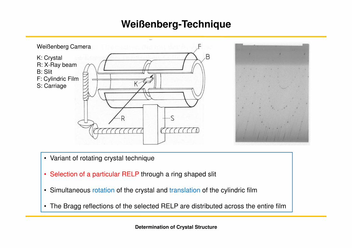
Weißenberg-Technique
K: CrystalR: X-Ray beamB: SlitF: Cylindric FilmS: Carriage
Weißenberg Camera
• Variant of rotating crystal technique
• Selection of a particular RELP through a ring shaped slit
• Simultaneous rotation of the crystal and translation of the cylindric film
• The Bragg reflections of the selected RELP are distributed across the entire film
Determination of Crystal Structure
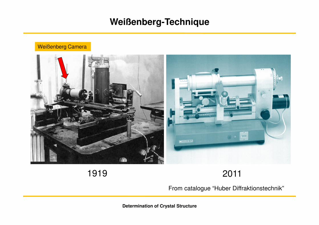
1919 2011
From catalogue “Huber Diffraktionstechnik”
Determination of Crystal Structure
Weißenberg Camera
Weißenberg-Technique
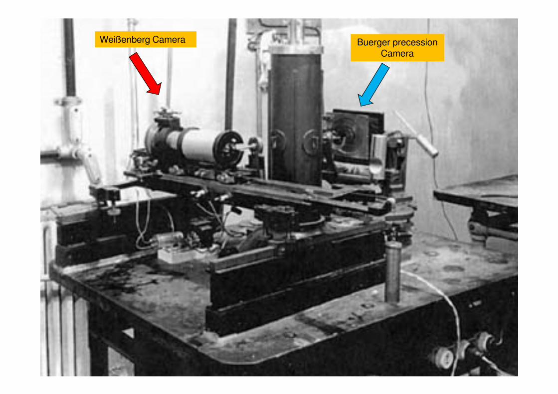
Weißenberg Camera Buerger precession Camera
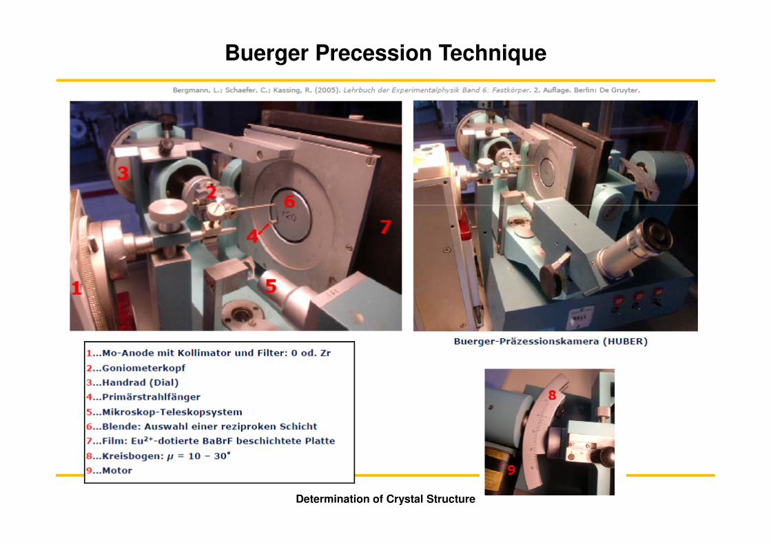
Buerger Precession Technique
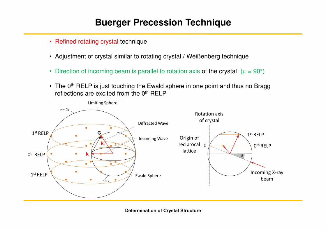
• Refined rotating crystal technique
• Adjustment of crystal similar to rotating crystal / Weißenberg technique
• Direction of incoming beam is parallel to rotation axis of the crystal (µ = 90°)
• The 0th RELP is just touching the Ewald sphere in one point and thus no Bragg reflections are excited from the 0th RELP
Determination of Crystal Structure
Limiting Sphere
Diffracted Wave
Incoming Wave
Ewald Sphere-1st RELP
0th RELP
1st RELP
Rotation axis
of crystal
Incoming X-ray
beam
Origin of
reciprocal
lattice
1st RELP
0th RELP
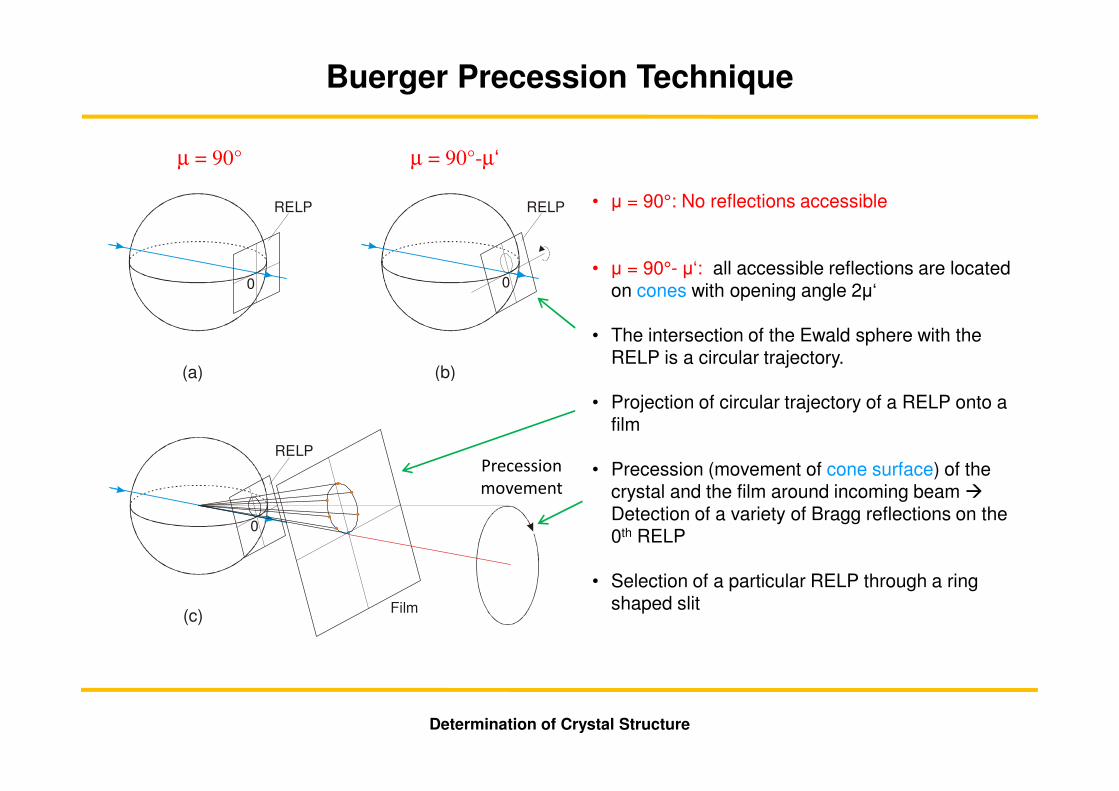
• µ = 90°: No reflections accessible
• µ = 90°- µ‘: all accessible reflections are located on cones with opening angle 2µ‘
• The intersection of the Ewald sphere with the RELP is a circular trajectory.
• Projection of circular trajectory of a RELP onto a film
• Precession (movement of cone surface) of the crystal and the film around incoming beam �Detection of a variety of Bragg reflections on the 0th RELP
• Selection of a particular RELP through a ring shaped slit
Determination of Crystal Structure
Buerger Precession Technique
0
RELP
(a)
0
RELP
(b)
0
RELP
(c) Film
Präzessions-bewegung
µ = 90° µ = 90°-µ‘
Precession
movement
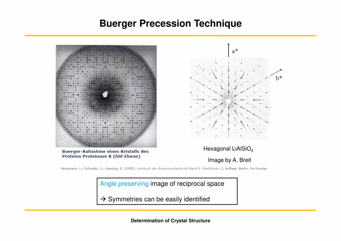
Image by A. Breit
Hexagonal LiAlSiO4
Angle preserving image of reciprocal space
� Symmetries can be easily identified
Determination of Crystal Structure
Buerger Precession Technique
Determination of Crystal Structure
Buerger Precession Technique
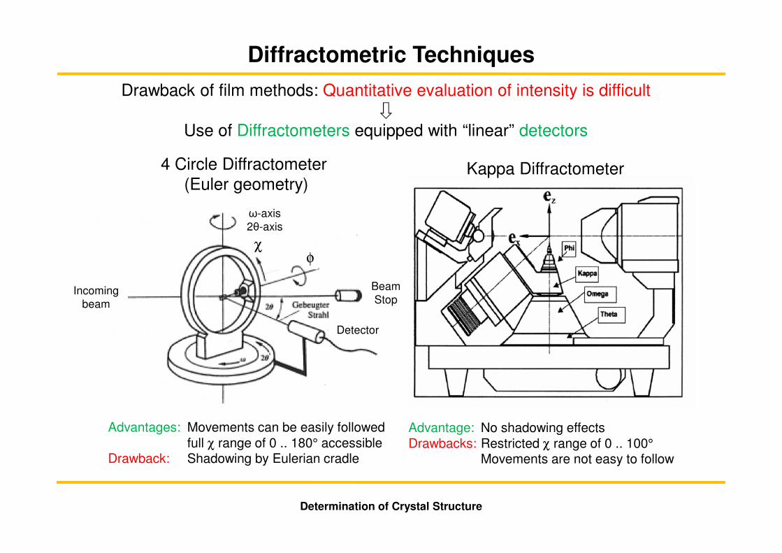
Diffractometric Techniques
4 Circle Diffractometer(Euler geometry)
Kappa Diffractometer
Advantage: No shadowing effectsDrawbacks: Restricted χ range of 0 .. 100°
Movements are not easy to follow
Drawback of film methods: Quantitative evaluation of intensity is difficult
Use of Diffractometers equipped with “linear” detectors
Advantages: Movements can be easily followed full χ range of 0 .. 180° accessible
Drawback: Shadowing by Eulerian cradle
Determination of Crystal Structure
Incoming beam
ω-axis2θ-axis
Detector
BeamStop
χφ

Sample adjustment
• Precise positioning of the sample with respect to the center of rotation of the diffractometer is required
Determination of the crystal unit cell dimension � (a1, a2, a3)
• “Peak Hunting”: Find some (20 ..50) strong Bragg reflections • Determination of so-called “orientation matrix”• Now, every Bragg reflection can be found by just typing in the Miller indices (hkl)
Automatic measurement of a large variety of Bragg reflections
• Systematic search and measurement of Bragg reflections in reciprocal space• Continued measurement of intense reference Bragg reflections
� Checking constant power of x-ray source� Checking the state of the crystal (stability, radiation damage, …)
• Procedure may take about one day for 500-1000 reflections for a point detector
Determination of Crystal Structure
Diffractometric Techniques
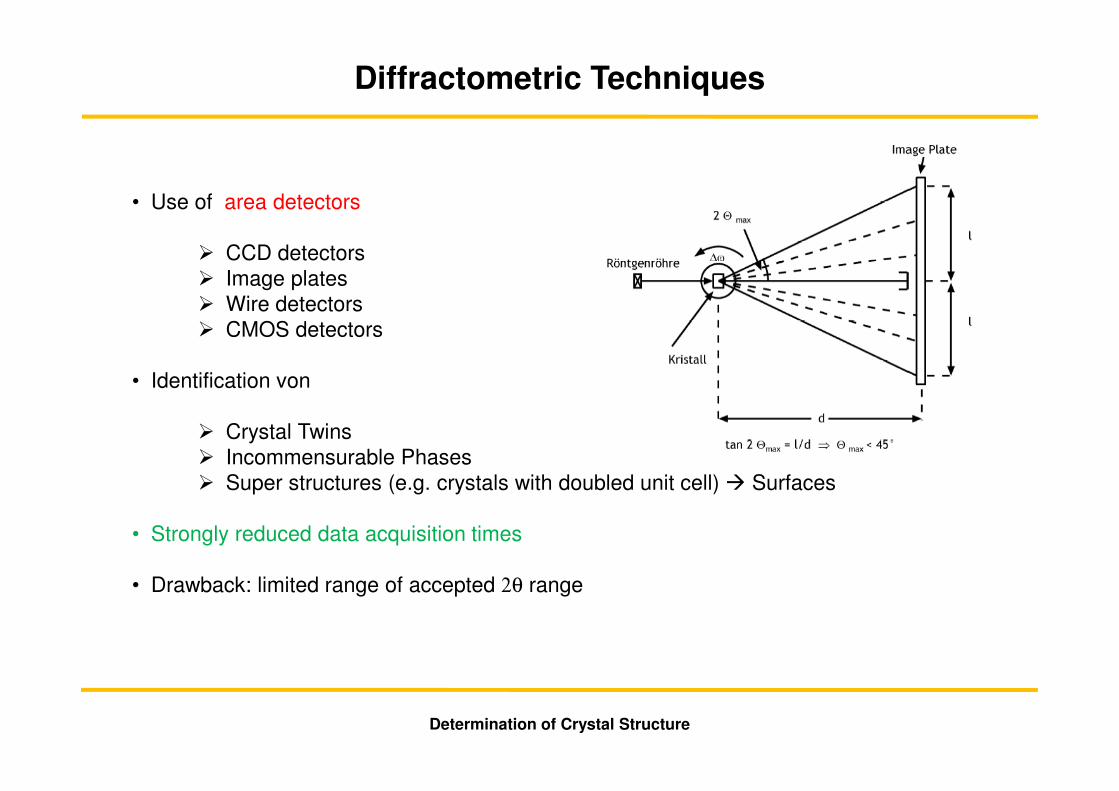
• Use of area detectors
� CCD detectors� Image plates� Wire detectors � CMOS detectors
• Identification von
� Crystal Twins� Incommensurable Phases� Super structures (e.g. crystals with doubled unit cell) � Surfaces
• Strongly reduced data acquisition times
• Drawback: limited range of accepted 2θ range
Determination of Crystal Structure
Diffractometric Techniques
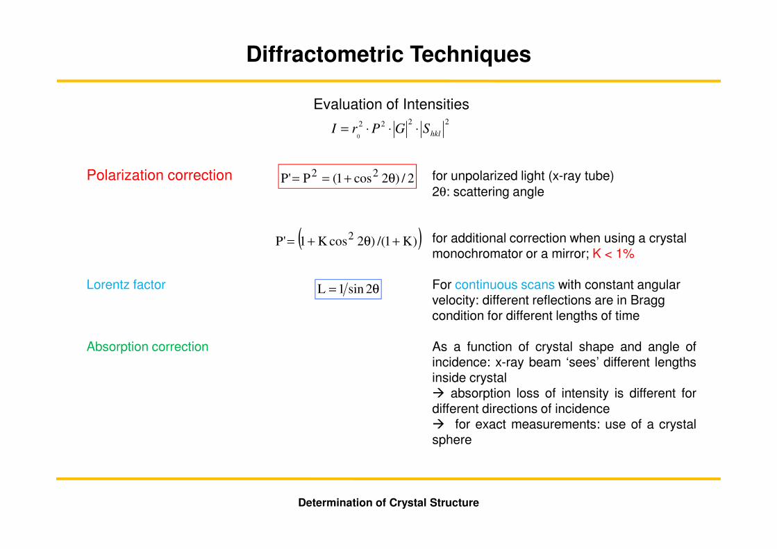
Evaluation of Intensities
Polarization correction for unpolarized light (x-ray tube)2θ: scattering angle
for additional correction when using a crystal monochromator or a mirror; K < 1%
Lorentz factor For continuous scans with constant angular velocity: different reflections are in Bragg condition for different lengths of time
Absorption correction As a function of crystal shape and angle ofincidence: x-ray beam ‘sees’ different lengthsinside crystal� absorption loss of intensity is different fordifferent directions of incidence� for exact measurements: use of a crystalsphere
2222
0 hklSGPrI ⋅⋅⋅=
2/)2cos1(P'P 22 θ+==
( ))K1/()2cosK1'P 2 +θ+=
θ= 2sin1L
Determination of Crystal Structure
Diffractometric Techniques
Determination of Crystal Structure
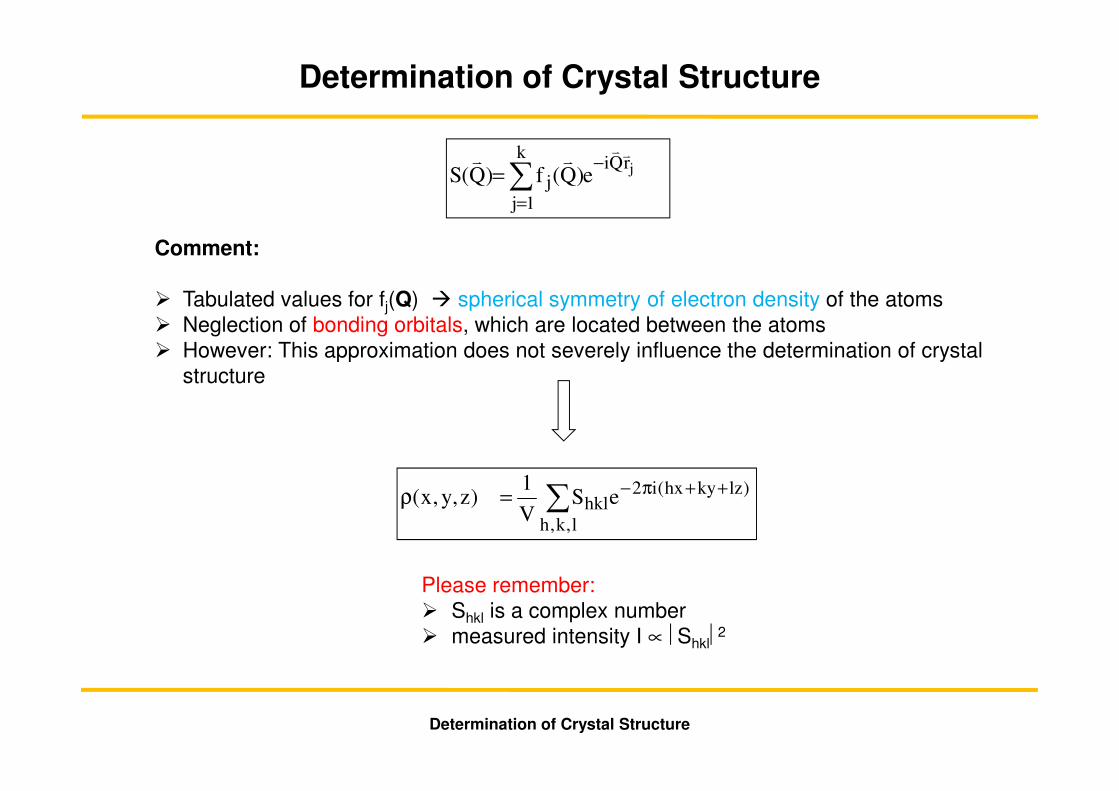
∑ ++π−=ρl,k,h
)lzkyhx(i2hkleS
V
1)z,y,x(
∑=
−=
k
1j
rQij
je)Q(f)Q(Svvvv
Comment:
� Tabulated values for fj(Q) � spherical symmetry of electron density of the atoms� Neglection of bonding orbitals, which are located between the atoms� However: This approximation does not severely influence the determination of crystal
structure
Determination of Crystal Structure
Please remember: � Shkl is a complex number� measured intensity I ∝ Shkl
2
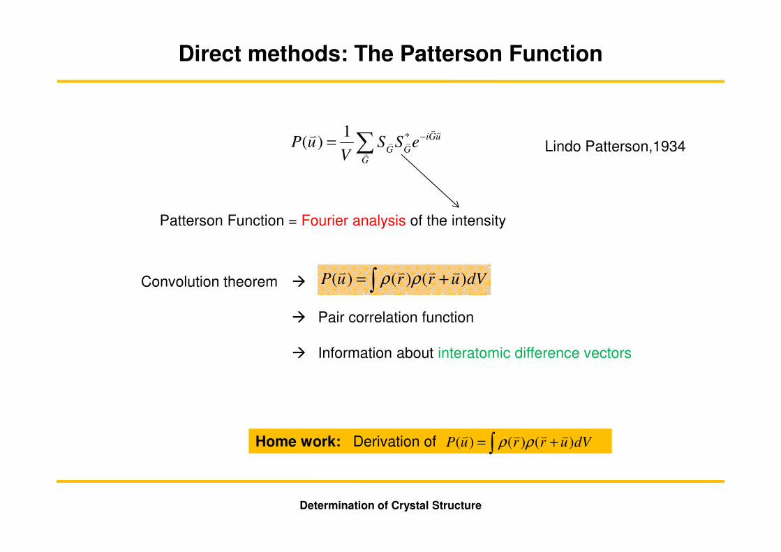
Direct methods: The Patterson Function
uGi
GGGeSS
VuP
vv
v
vvv −∑= *1)(
Patterson Function = Fourier analysis of the intensity
Convolution theorem �
� Pair correlation function
� Information about interatomic difference vectors
dVurruP )()()(vvvv
+= ∫ ρρ
Lindo Patterson,1934
Home work: Derivation of dVurruP )()()(vvvv
+= ∫ ρρ
Determination of Crystal Structure

• Equivalent translational symmetry of ρ(r) and P(u)
• Size of unit cells of electron density and of Patterson function are identical
• Atomic structure consists of N atoms � Patterson function exhibits N(N-1)+1 Peaks
• Maximum of Patterson-Function appears at origin (u = 0)
• Patterson-Function is centrosymmetric even if electron density is not centrosymmetric.
• Reason: For each vector uAB pointing from atom A to atom B there exists the opposite vector uBA = - uAB pointing from atom B to atom A
• Symmetry properties of Patterson function leads to the 24 Patterson groups
Properties of the Patterson Function
Determination of Crystal Structure
u = 0
Direct methods: The Patterson Function

Advantages of Patterson Technique
• The Patterson function provides a ‘Map‘ of interatomic distances in real space
• Maxima of Patterson function appear at locations u, which represent the distance vectors between two atoms
• So we see interatomic distances
• Implementation in many data evaluation programs (e.g. SHELXS-97:PATT)
V. Sasisekharan,1956
“Typical“ Patterson function (Patterson map)
Determination of Crystal Structure
Direct methods: The Patterson Function
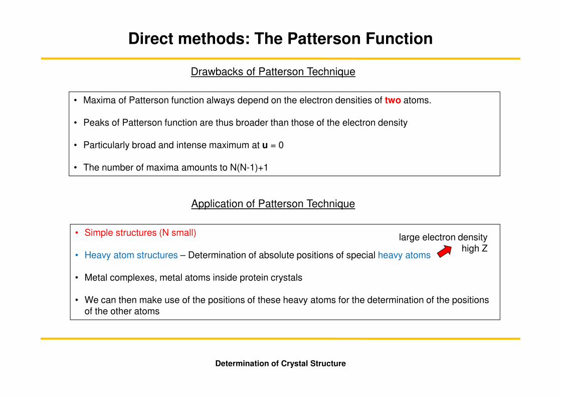
• Maxima of Patterson function always depend on the electron densities of two atoms.
• Peaks of Patterson function are thus broader than those of the electron density
• Particularly broad and intense maximum at u = 0
• The number of maxima amounts to N(N-1)+1
Drawbacks of Patterson Technique
• Simple structures (N small)
• Heavy atom structures – Determination of absolute positions of special heavy atoms
• Metal complexes, metal atoms inside protein crystals
• We can then make use of the positions of these heavy atoms for the determination of the positions of the other atoms
Application of Patterson Technique
Determination of Crystal Structure
Direct methods: The Patterson Function
large electron densityhigh Z
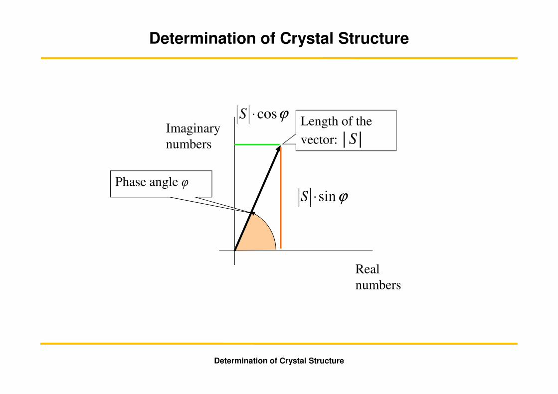
Imaginary
numbers
Real
numbers
Length of the
vector: │S│
Phase angle φϕsin⋅S
ϕcos⋅S
Determination of Crystal Structure
Determination of Crystal Structure
Direct Methods
Principle/Idea:
• Direct determination of phases of the scattered waves directly (‘brute force‘) from the experimental data set
• There is no common solution of this problem
• Helpful for finding a physical solution is:
� Electron density ρ(r) is a positive number (ρ(r) > 0)
� ρ(r) is concentrated at the atomic positions (discrete density)
• Direct methods are working since many reflections are at disposal for the determination of just a small number of parameters
� Overdetermined system of equations
� Statistical methods
Determination of Crystal Structure
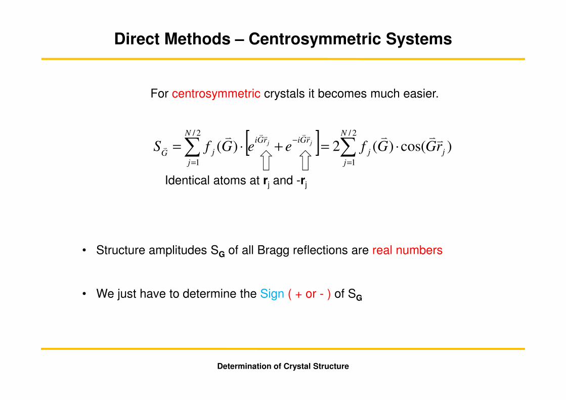
Direct Methods – Centrosymmetric Systems
For centrosymmetric crystals it becomes much easier.
• Structure amplitudes SG of all Bragg reflections are real numbers
• We just have to determine the Sign ( + or - ) of SG
[ ] )cos()(2)(2/
1
2/
1
j
N
j
j
rGirGiN
j
jGrGGfeeGfS jjvvvv vvvv
v ⋅=+⋅= ∑∑=
−
=
Determination of Crystal Structure
Identical atoms at rj and -rj

Apply the Cauchy-Schwartz Inequality
to the Integral
Then we can make predictions for the so-called unitary structure factors
(Z is the number of electrons in unit cell)
concerning the probability of the sign (phase) of the structure factor
Harker Kasper In-Equations (1948)
Uhkl = Shkl/Z
dxdydzezyxSlzkyhxi
lkh
)(2
,, ),,( ++−
∫∫∫= πρ
Determination of Crystal Structure
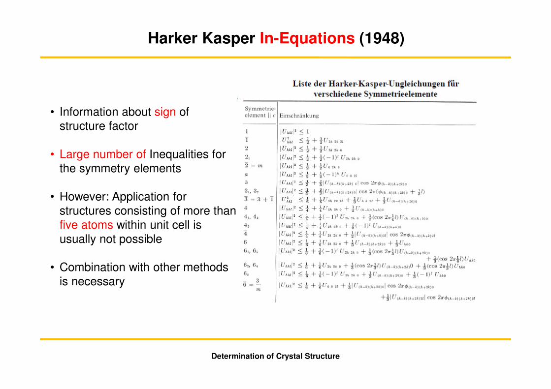
• Information about sign of structure factor
• Large number of Inequalities for the symmetry elements
• However: Application for structures consisting of more than five atoms within unit cell is usually not possible
• Combination with other methods is necessary
Determination of Crystal Structure
Harker Kasper In-Equations (1948)
∑ −=
'''
GGGGG
SSkSv
vvvv
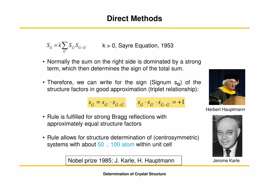
Nobel prize 1985: J. Karle, H. Hauptmann
'' GGGGsss vvvv
−⋅= 1
''+=⋅⋅
−GGGGsss vvvv
k > 0, Sayre Equation, 1953
• Normally the sum on the right side is dominated by a strongterm, which then determines the sign of the total sum.
• Therefore, we can write for the sign (Signum sG) of thestructure factors in good approximation (triplet relationship):
• Rule is fulfilled for strong Bragg reflections with approximately equal structure factors
• Rule allows for structure determination of (centrosymmetric) systems with about 50 .. 100 atom within unit cell
Jerome Karle
Herbert Hauptmann
Determination of Crystal Structure
Direct Methods

Determination of Crystal Structure
So far we have focused on centrosymmetric structures
Is there a way to gain access to non-centrosymmetric structures?
Direct Methods – Centrosymmetric Systems

Electron density of a single atom: ρA(r)
)Q(fR
ePEre)r(dV
R
ePEr)Q,R(E
ikR
00rQi
A
ikR
00rad
vvvv vv
=ρ= ∫⋅−
atomic scattering factor (amplitude)atomic form factor
∫⋅−ρ= rQi
A e)r(dV)Q(fvv
vv
Scattering VectorA
tom
ic S
catt
eri
ng
Fa
cto
r0
Z
‘delocalized’density
‘localized’density
experimental/calculated values are listed in:
International Tables of Crystallography
or
http://henke.lbl.gov/optical_constants/asf.html
Brief Reminder: Atomic Form Factor
f(Q) is a real number
Determination of Crystal Structure
Independent of X-ray energy
f(Q) = f(-Q)
Resonant Scattering (Anomalous Dispersion)
Hönl corrections
Determination of Crystal Structure
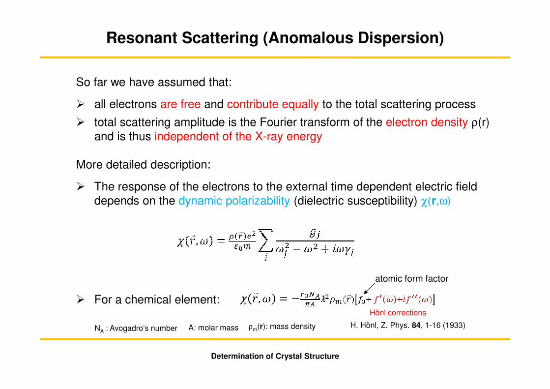
So far we have assumed that:
� all electrons are free and contribute equally to the total scattering process
� total scattering amplitude is the Fourier transform of the electron density ρ(r) and is thus independent of the X-ray energy
More detailed description:
� The response of the electrons to the external time dependent electric field depends on the dynamic polarizability (dielectric susceptibility) χ(r,ω)
� For a chemical element:
atomic form factor
NA : Avogadro‘s number A: molar mass ρm(r): mass density H. Hönl, Z. Phys. 84, 1-16 (1933)

� We see a remarkable effect on χ(r, ω) in the proximity of absorption edges only !
Adapted from: H.-G. Haubold, Jülich
Determination of Crystal Structure
Resonant Scattering (Anomalous Dispersion)
100 eV
∆f/f ≈ 20% Real partf0 + f’(ω)
Imaginary partμ ∝ f’’(ω)
f’(ω) and f’’(ω) areinterconnected via a Kramers-KronigRelationship
ωωω
ω
π
ωω
ωωω
ωω
πω
df
Pf
df
Pf
∫
∫∞
∞
−⋅=
−⋅=
0
22
0
22
'
)'('2)(''
''
)'('''2)('
µ: Linear Absorption Coefficient
f0 = Z
Determination of Crystal Structure
Resonant Scattering (Anomalous Dispersion)
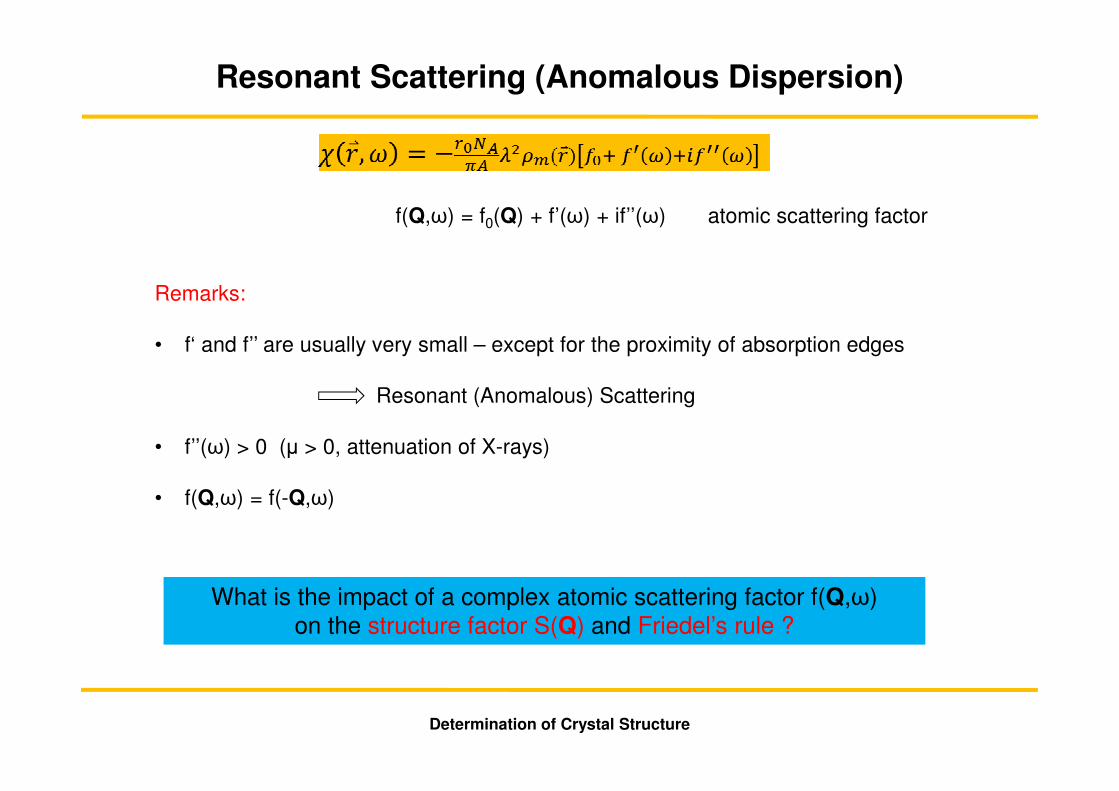
f(Q,ω) = f0(Q) + f’(ω) + if’’(ω) atomic scattering factor
What is the impact of a complex atomic scattering factor f(Q,ω) on the structure factor S(Q) and Friedel’s rule ?
Remarks:
• f‘ and f’’ are usually very small – except for the proximity of absorption edges
Resonant (Anomalous) Scattering
• f’’(ω) > 0 (µ > 0, attenuation of X-rays)
• f(Q,ω) = f(-Q,ω)
Determination of Crystal Structure
Resonant Scattering (Anomalous Dispersion)
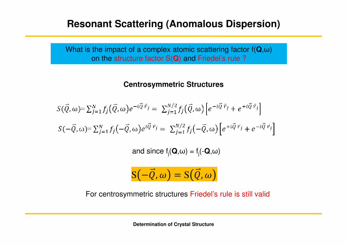
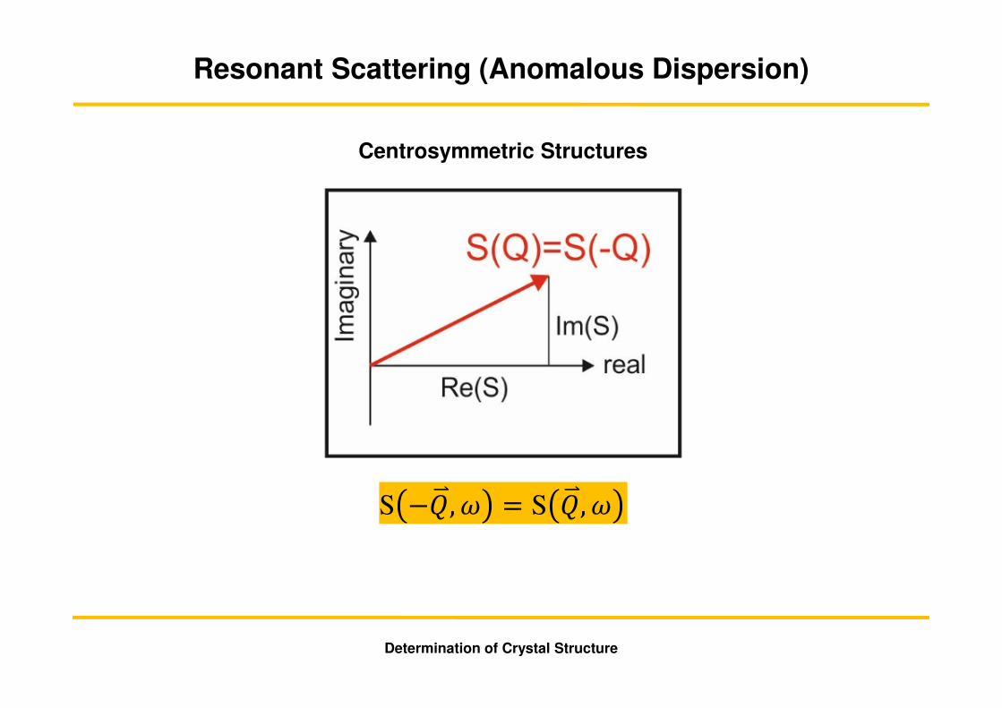
Centrosymmetric Structures
and since fj(Q,ω) = fj(-Q,ω)
For centrosymmetric structures Friedel’s rule is still valid
S −�,� = S �,�
What is the impact of a complex atomic scattering factor f(Q,ω) on the structure factor S(Q) and Friedel’s rule ?
Determination of Crystal Structure
Resonant Scattering (Anomalous Dispersion)
Centrosymmetric Structures
S −�,� = S �,�
Determination of Crystal Structure
Resonant Scattering (Anomalous Dispersion)
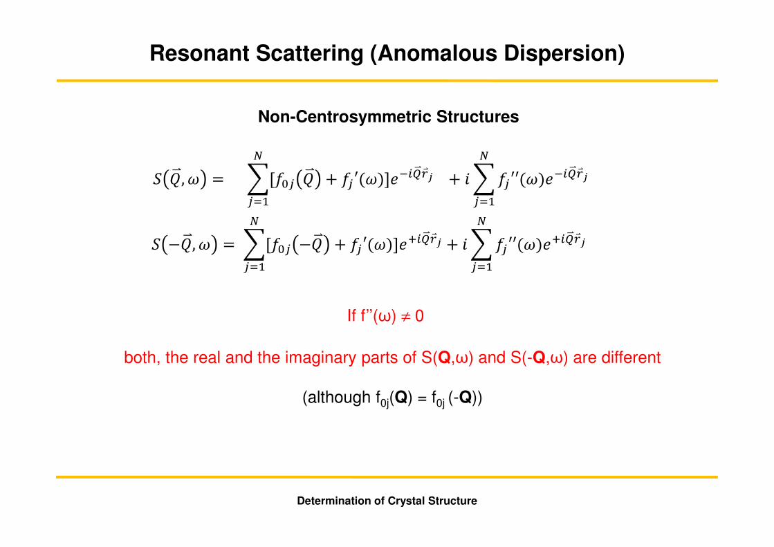
Non-Centrosymmetric Structures
� −�,� = �[�� −� + �′(�)]��������
���+ ���′′(�)�������
�
���
� �,� = �[�� � + �′(�)]��������
���+ ���′′(�)�������
�
���
both, the real and the imaginary parts of S(Q,ω) and S(-Q,ω) are different
(although f0j(Q) = f0j (-Q))
If f’’(ω) ≠ 0
Determination of Crystal Structure
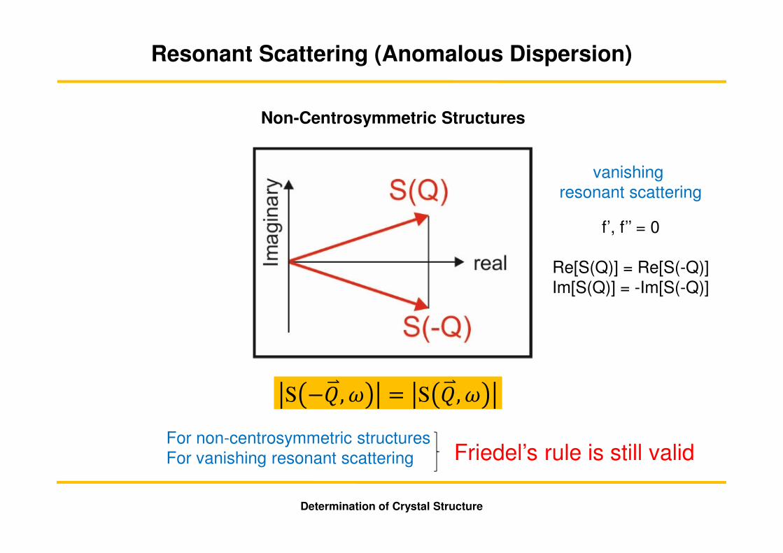
Resonant Scattering (Anomalous Dispersion)
f’, f’’ = 0
Re[S(Q)] = Re[S(-Q)]Im[S(Q)] = -Im[S(-Q)]
For non-centrosymmetric structures For vanishing resonant scattering
Non-Centrosymmetric Structures
Friedel’s rule is still valid
S −�,� = S �,�
vanishing resonant scattering

Determination of Crystal Structure
Resonant Scattering (Anomalous Dispersion)
f’, f’’ ≠ 0
Re[S(Q)] ≠ Re[S(-Q)]Im[S(Q)] ≠ -Im[S(-Q)]
For non-centrosymmetric structures For non vanishing resonant scattering
Non-Centrosymmetric Structures
S −�,� ≠ S �,�
Appearance of resonant scattering
Friedel’s rule is broken
The modifications in S(Q) and S(-Q) are induced by atoms which experience resonant dispersion
Determination of Crystal Structure
Resonant Scattering (Anomalous Dispersion)
Determination of Crystal Structure
Resonant Scattering (Anomalous Dispersion)
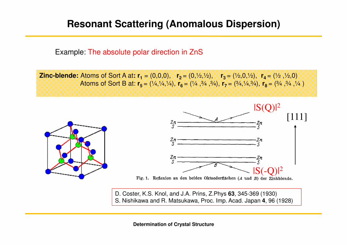
Example: The absolute polar direction in ZnS
Zinc-blende: Atoms of Sort A at: r1 = (0,0,0), r2 = (0,½,½), r3 = (½,0,½), r4 = (½ ,½,0)Atoms of Sort B at: r5 = (¼,¼,¼), r6 = (¼ ,¾ ,¾), r7 = (¾,¼,¾), r8 = (¾ ,¾ ,¼ )
D. Coster, K.S. Knol, and J.A. Prins, Z.Phys 63, 345-369 (1930)S. Nishikawa and R. Matsukawa, Proc. Imp. Acad. Japan 4, 96 (1928)
[111]|S(Q)|2
|S(-Q)|2
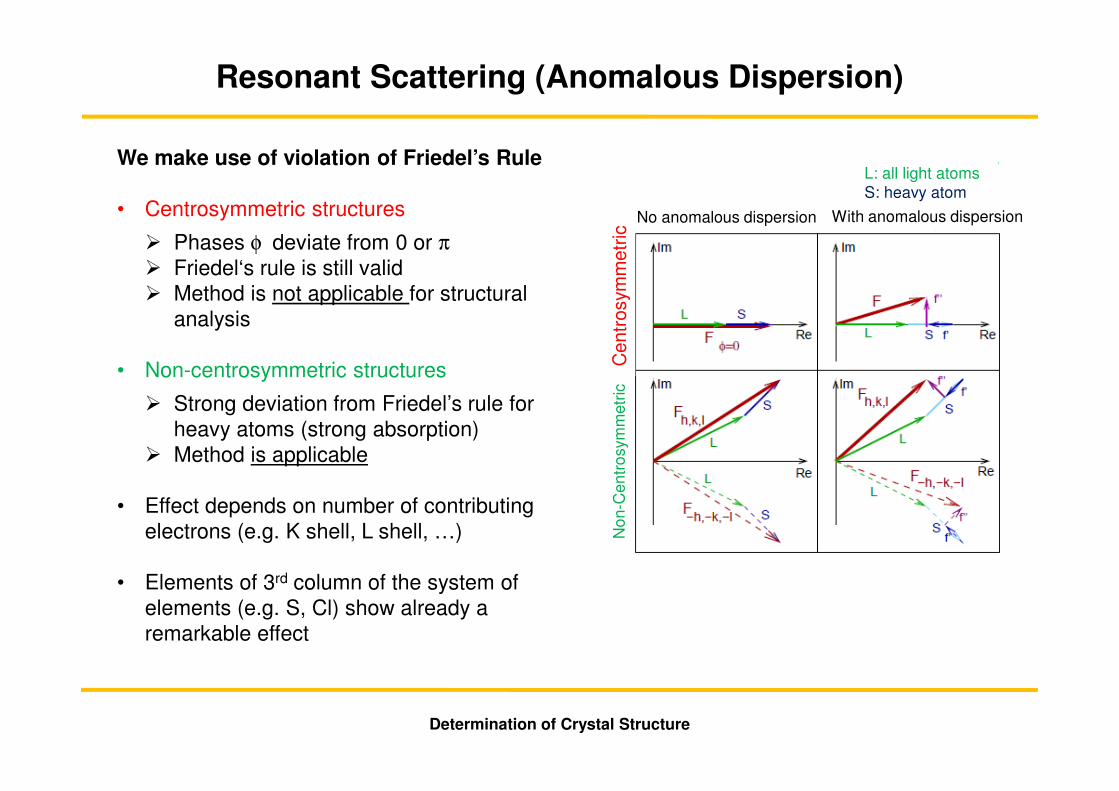
We make use of violation of Friedel’s Rule
• Centrosymmetric structures
� Phases φ deviate from 0 or π� Friedel‘s rule is still valid� Method is not applicable for structural
analysis
• Non-centrosymmetric structures
� Strong deviation from Friedel’s rule for heavy atoms (strong absorption)
� Method is applicable
• Effect depends on number of contributing electrons (e.g. K shell, L shell, …)
• Elements of 3rd column of the system of elements (e.g. S, Cl) show already a remarkable effect
Determination of Crystal Structure
Resonant Scattering (Anomalous Dispersion)
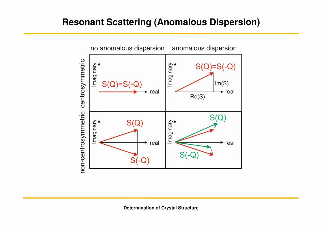
Cen
tros
ymm
etric
Non
-Cen
tros
ymm
etric
Cen
tros
ymm
etric
With anomalous dispersionNo anomalous dispersion
L: all light atomsS: heavy atom
Determination of Crystal Structure
Resonant Scattering (Anomalous Dispersion)
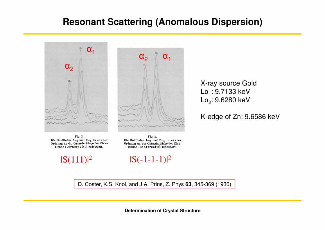
D. Coster, K.S. Knol, and J.A. Prins, Z. Phys 63, 345-369 (1930)
|S(111)|2 |S(-1-1-1)|2
X-ray source Gold Lα1: 9.7133 keVLα2: 9.6280 keV
K-edge of Zn: 9.6586 keV
α1
α2
α2 α1
Literature
• http://ruby.chemie.uni-freiburg.de/Vorlesung/Seminare/afp_strukturbestimmung.pdf• W. Massa: Einführung in die Kristallstrukturanalyse, Teubner.• Giacovazzo et al. (ed.): Fundamentals of Crystallography, Oxford.
Software
• z.B. SHELXS-97 (G. Sheldrick, Göttingen)
Databases
• ICSD (Inorganic Crystal Structure Database): Inorganics without intermetallic phases (expensive)
• Pearsons Crystal Data: Intermetallic Phases + Inorganics (very expensive)• Pauling-File (Intermetallic Phases) (free registration)• CSD (Cambridge Crystallographic Database) (Organics, Metal-Organics) (expensive)• PDB (Protein Database) (freely available on the web)
Literature, Software, Databases
Determination of Crystal Structure


![¾Crystal structure is defined as a regular of atoms ... · Difração de Elétrons [6] 1> ¾Representation of a general unit cell: ¾Crystal structure is defined as a regular of](https://static.fdocument.org/doc/165x107/5f0564367e708231d412bae7/crystal-structure-is-defined-as-a-regular-of-atoms-difrao-de-eltrons.jpg)