HNA ITM TechData MIC T V1 2 08 2017 new Safety Factor (omega) > 1.0 as per AISC specifications. 2....
10
MIC-T 304807 Hilti North America Installation Technical Manual Technical Data MI System Version 1.2 08.2017
Transcript of HNA ITM TechData MIC T V1 2 08 2017 new Safety Factor (omega) > 1.0 as per AISC specifications. 2....

MIC-T304807Hilti North AmericaInstallation Technical ManualTechnical DataMI System
Version 1.2 08.2017

2
Installation Technical Manual - Technical Data - MI system
Boundary conditions - Terms of common cooperation / Legal disclaimer and guidelines as defined at the beginning of this book need to be mandatorily respected.
Terms of common cooperation /Legal disclaimerThe product technical data published in these Technical Data Sheets are only valid for the mentioned codes or technical data generation methods and the defined application conditions (e.g. ambient temperature load capacity not valid in case of fire, data not valid in support structures when mixed with third party products, values only apply to static loading conditions). Technical data applies to the component only -- suitability and capacity of all other components must be checked separately by the responsible engineer (e.g., other assembly components, attachments, base materials, and building structures).Suitability of structures combining different products for specific applications needs to be verified by conducting a system design and calculation, using for example Hilti PROFIS software. In addition, it is crucial to fully respect the Instructions for Use and to assure clean, unaltered and undamaged state of all products at any time in order to achieve optimum performance(e.g. avoid misuse, modification, overload, corrosion).As products but also technical data generation methodologies evolve over time, technical data might change at any time without prior notice. We recommend to use the latest technical data sheets published by Hilti.
In any case the suitability of structures combining different products for specific applications need to be checked and cleared by an expert, particularly with regard to compliance with applicable norms, codes, and project specific requirements, prior to using them for any specific facility. This book only serves as an aid to interpret the capacity of the components listed,without any guarantee as to the absence of errors, the correctness and the relevance of the results or suitability for a specific application. User must take all necessary and reasonable steps to prevent or limit damage. The suitability of structures combining different products for specific applications need to be confirmed with a professional designer and/or structural engineers to ensure compliance with User`s specific jurisdiction and project requirements.

3
Installation Technical Manual - Technical Data - MI system
Boundary conditions - Terms of common cooperation / Legal disclaimer and guidelines as defined at the beginning of this book need to be mandatorily respected.
Data version 1.2 I Date 08.2017
MIC-T Connector
Page 1/6
Designation Item numberMIC-T 304807
Corrosion protection:Hot dipped galvanized per DIN EN ISO 1461: Connector: 2.2 mils (55 μm) Tooth plate: 1.8 mils (45 μm) Bolt: 1.8 mils (45 μm) Nut: 1.8 mils (45 μm)
Weight:5.53 lb ( 2510 g) incl. components
Descriptions:Hot dipped galvanized, 90° Hilti MI angle connector, typically used for connecting two perpendicular MI girders, where the horizontal girder sits on top of the vertical girder. Oblong holes enable fine adjustment and are serrated to improve holding and load values. Connector is used on the side of the girders.
Instruction For Use:
Material propertiesMaterial Yield strength Ultimate strength E-modulus Shear modulusConnector and Toothed plate:
S235JR - DIN EN10025-2 2005.4 fy = 34.08 ksi (235 ) fu = 52.21 ksi (360
) 29000 ksi (200000 ) 11000 ksi (75845 )
One hand screw, prevail torque hex nut
Class 8.8 - DIN EN 1993-1-8 fy = 92.82 ksi (640 ) fu = 116.03 ksi (800
) 29000 ksi (200000 ) 11000 ksi (75845 )
1xpair of MIC-T
2x MIA-TP
2xM12-F-SL-WS 3/4"
1x MIA-EH90
Hardware included per connector
4
Installation Technical Manual - Technical Data - MI system
Boundary conditions - Terms of common cooperation / Legal disclaimer and guidelines as defined at the beginning of this book need to be mandatorily respected.
Data version 1.2 I Date 08.2017
MIC-T Connector
Page 2/6
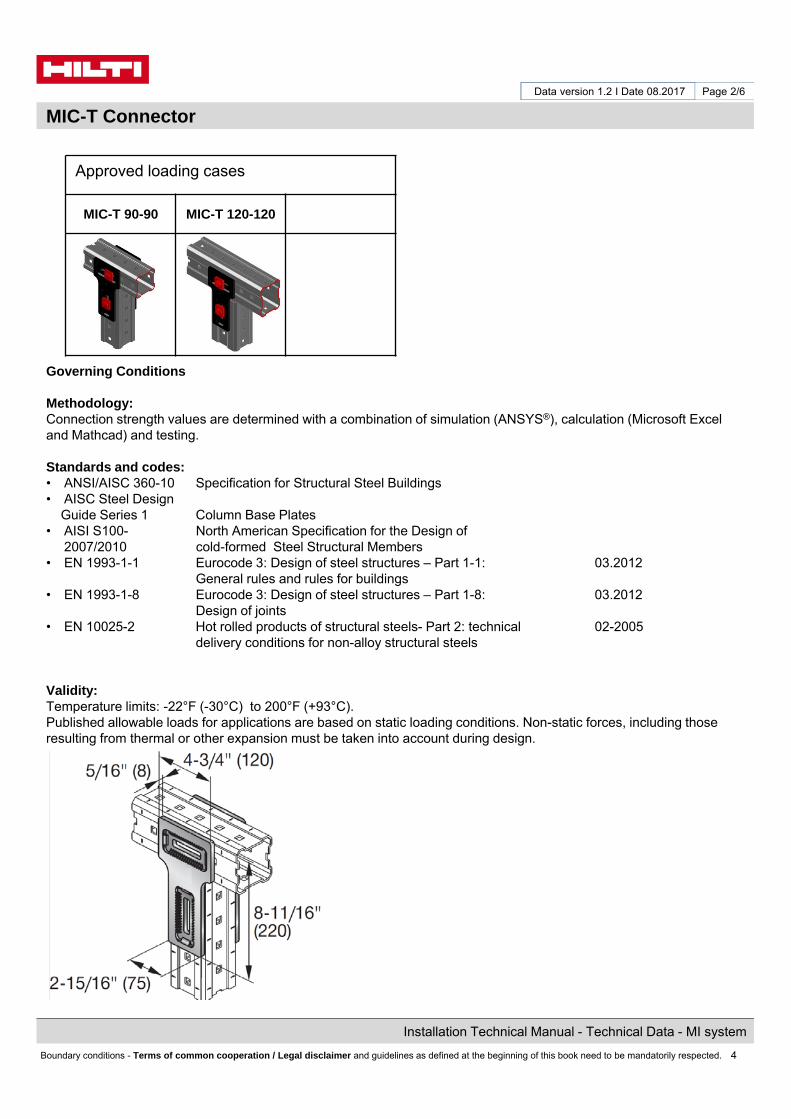
Approved loading cases
MIC-T 90-90 MIC-T 120-120
Governing Conditions
Methodology:Connection strength values are determined with a combination of simulation (ANSYS®), calculation (Microsoft Excel and Mathcad) and testing.
Standards and codes:• ANSI/AISC 360-10 Specification for Structural Steel Buildings• AISC Steel Design
Guide Series 1 Column Base Plates• AISI S100- North American Specification for the Design of
2007/2010 cold-formed Steel Structural Members• EN 1993-1-1 Eurocode 3: Design of steel structures – Part 1-1: 03.2012
General rules and rules for buildings• EN 1993-1-8 Eurocode 3: Design of steel structures – Part 1-8: 03.2012
Design of joints• EN 10025-2 Hot rolled products of structural steels- Part 2: technical 02-2005
delivery conditions for non-alloy structural steels
Validity:Temperature limits: -22°F (-30°C) to 200°F (+93°C).Published allowable loads for applications are based on static loading conditions. Non-static forces, including thoseresulting from thermal or other expansion must be taken into account during design.

5
Installation Technical Manual - Technical Data - MI system
Boundary conditions - Terms of common cooperation / Legal disclaimer and guidelines as defined at the beginning of this book need to be mandatorily respected.
Data version 1.2 I Date 08.2017
MIC-T Connector
Page 3/6
MIC-T 90-90 MIC-T 120-120
Loading case: MIC-T 90-90 Combinations covered by loading case
Bill of Material for this loading case:
Connector incl. all packaged hardware
1x MIC-T 304807
Connector used for perpendicular connections of two MI-90 girders, where Horizontal girder sits on top of the vertical girder
Usage of Values for Design Strength and Allowable Strength
Limiting components of capacity evaluated in following tables:
Connection system, including connector, hardware and affected portion of MI-90 girders, per FEA simulation
The Design Strength and Allowable Strength tables on the following pages include strength reduction factors:
1. ASD: Safety Factor (omega) > 1.0 as per AISC specifications.
2. LRFD: Strength Reduction Factor (phi) < 1.0 as per AISC specifications. Ω.
ф(Reference AISC 360 C-B3-5)
Factored loads are required for input to the given interaction equations. Factored loads are the responsibility of the user. Factored loads are noted as P, V and M
6
Installation Technical Manual - Technical Data - MI system
Boundary conditions - Terms of common cooperation / Legal disclaimer and guidelines as defined at the beginning of this book need to be mandatorily respected.
Data version 1.2 I Date 08.2017
MIC-T Connector
Page 4/6
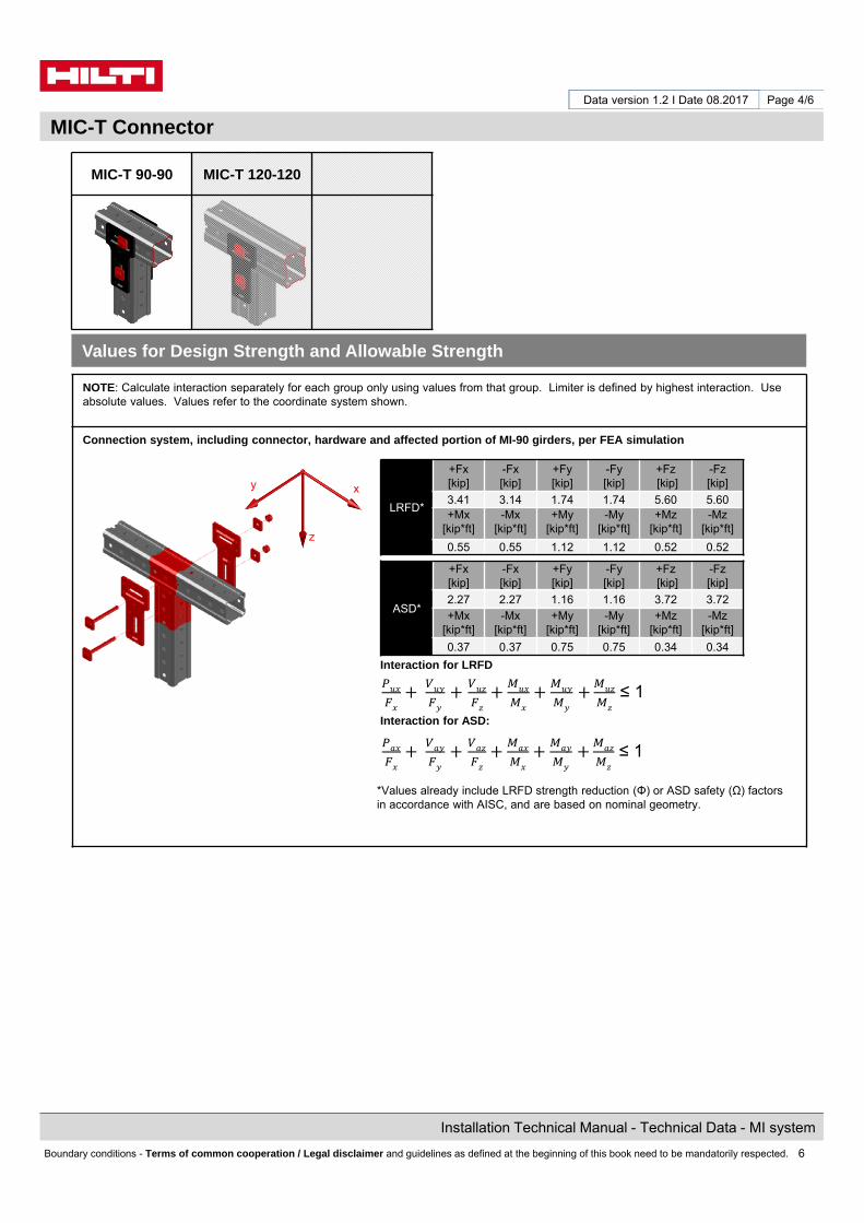
NOTE: Calculate interaction separately for each group only using values from that group. Limiter is defined by highest interaction. Use absolute values. Values refer to the coordinate system shown.
Connection system, including connector, hardware and affected portion of MI-90 girders, per FEA simulation
Interaction for LRFD
Interaction for ASD:
*Values already include LRFD strength reduction (Φ) or ASD safety (Ω) factors in accordance with AISC, and are based on nominal geometry.
Values for Design Strength and Allowable Strength
z
y x
LRFD*
+Fx[kip]
-Fx[kip]
+Fy[kip]
-Fy[kip]
+Fz[kip]
-Fz[kip]
3.41 3.14 1.74 1.74 5.60 5.60+Mx
[kip*ft]-Mx
[kip*ft]+My
[kip*ft]-My
[kip*ft]+Mz
[kip*ft]-Mz
[kip*ft]
0.55 0.55 1.12 1.12 0.52 0.52
ASD*
+Fx[kip]
-Fx[kip]
+Fy[kip]
-Fy[kip]
+Fz[kip]
-Fz[kip]
2.27 2.27 1.16 1.16 3.72 3.72+Mx
[kip*ft]-Mx
[kip*ft]+My
[kip*ft]-My
[kip*ft]+Mz
[kip*ft]-Mz
[kip*ft]
0.37 0.37 0.75 0.75 0.34 0.34
≤ 1
≤ 1
MIC-T 90-90 MIC-T 120-120

7
Installation Technical Manual - Technical Data - MI system
Boundary conditions - Terms of common cooperation / Legal disclaimer and guidelines as defined at the beginning of this book need to be mandatorily respected.
Data version 1.2 I Date 08.2017
MIC-T Connector
Page 5/6
MIC-T 90-90 MIC-T 120-120
Loading case: MIC-T 120-120 Combinations covered by loading case
Bill of Material for this loading case:
Connector incl. all connecting hardware
1x MIC-T 304807
Connector used For perpendicular connections of two MI-120 girders, where Horizontal girder sits on top of the vertical girder
Usage of Values for Design Strength and Allowable Strength
Limiting components of capacity evaluated in following tables:
Connection system, including connector, hardware and affected portion of MI-120 girders, per FEA simulation
The Design Strength and Allowable Strength tables on the following pages include strength reduction factors:
1. ASD: Safety Factor (omega) > 1.0 as per AISC specifications.
2. LRFD: Strength Reduction Factor (phi) < 1.0 as per AISC specifications. Ω.
ф(Reference AISC 360 C-B3-5)
Factored loads are required for input to the given interaction equations. Factored loads are the responsibility of the user. Factored loads are noted as P, V and M

8
Installation Technical Manual - Technical Data - MI system
Boundary conditions - Terms of common cooperation / Legal disclaimer and guidelines as defined at the beginning of this book need to be mandatorily respected.
Data version 1.2 I Date 08.2017
MIC-T Connector
Page 6/6
NOTE: Calculate interaction separately for each group only using values from that group. Limiter is defined by highest interaction. Use absolute values. Values refer to the coordinate system shown.
Connection system, including connector, hardware and affected portion of MI-120 girders, per FEA simulation
Interaction for LRFD
Interaction for ASD:
*Values already include LRFD strength reduction (Φ) or ASD safety (Ω) factors in accordance with AISC, and are based on nominal geometry.
Values for Design Strength and Allowable Strength
LRFD*
+Fx[kip]
-Fx[kip]
+Fy[kip]
-Fy[kip]
+Fz[kip]
-Fz[kip]
4.38 4.38 2.17 2.17 5.60 5.60+Mx
[kip*ft]-Mx
[kip*ft]+My
[kip*ft]-My
[kip*ft]+Mz
[kip*ft]-Mz
[kip*ft]
0.59 0.59 1.36 1.36 0.59 0.59
ASD*
+Fx[kip]
-Fxkip]
+Fy[kip]
-Fy[kip]
+Fz[kip]
-Fz[kip]
2.92 2.92 1.45 1.45 3.73 3.73+Mx
[kip*ft]-Mx
[kip*ft]+My
[kip*ft]-My
[kip*ft]+Mz
[kip*ft]-Mz
[kip*ft]
0.39 0.39 0.91 0.91 0.39 0.39
MIC-T 90-90 MIC-T 120-120
≤ 1
≤ 1
z
y x

9
Installation Technical Manual - Technical Data - MI system
Boundary conditions - Terms of common cooperation / Legal disclaimer and guidelines as defined at the beginning of this book need to be mandatorily respected.
Data version 1.2 I Date 08.2017
In the US: In Canada:Hilti, Inc. (U.S.) Hilti (Canada) CorporationP.O. Box 21148 Tulsa, OK 74121 2360 Meadowpine Blvd.Customer Service: 1-800-879-8000 Mississauga, Ontario, L5N 6S2en español: 1-800-879-5000 Customer Service: 1-800-363-4458Fax: 1-800-879-7000 Fax: 1-800-363-4459
www.us.hilti.com www.hilti.ca
Hilti is an equal opportunity employerHilti is a registered trademark of Hilti, Corp.©Copyright 2017 by Hilti, Inc. (U.S.)
The data contained in this literature was current as of the date of publication. Updates and changes may be made based on later testing. If verification is needed that the data is still current, please contact the Hilti Technical Support Specialists at 1-800-879-8000 (U.S.) or 1-800-363-4458 (Canada). All published load values contained in this literature represent the result of testing by Hilti or test organizations. Local base materials were used. Because of variations in materials, on-site testing is necessary to determinate performance at any specific site.