Getting Started of μPAC-7186EG(D)/PEG(D) & I … · 1.2 Remote I/O Modules and Expansion...
92
.Getting Started: PAC-7186EG(D)/PEG(D) & I-7188EG(D)/XG(D) Ver. 3.9, 10/2014 ICP DAS .1 Getting Started of μPAC-7186EG(D)/PEG(D) & I-7188EG(D)/XG(D) This manual is intended for integrators, programmers, and maintenance personnel who will be installing and maintaining a μPAC-7186EG/PEG & an I-7188EG/XG controller system. ISaGRAF PAC Series of ICP DAS includes : μPAC: μPAC-7186EG/PEG, μPAC-5xx7 Series, I-7188EG, I-7188XG iPAC: iP-8xx7 Series, I-8xx7 Series WinPAC: WP-8xx7 Series, WP-5xx7 Series ViewPAC: VP-2xW7/4xx7 Series, VP-2117 XPAC: XP-8xx7-CE6 Series, XP-8xx7-Atom-CE6 Series Legal Liability ICP DAS CO., LTD. assumes no liability for any and all damages that may be incurred by the user as a consequence of this product. ICP DAS CO., LTD. reserves the right to change this manual at any time without notice. ICP DAS CO., LTD. constantly strives to provide our customers with the most reliable and accurate information possible regarding our products. However, ICP DAS CO., LTD. assumes no responsibility for its use, or for any infringements of patents or other rights of third parties resulting from its use. Trademark & Copyright Notice The names of products are used for identification purposes only, and are the registered trademarks of their respective owners or companies. Technical Service: Please contact local agent or email problem-report to [email protected]. New information can be found at www.icpdas.com. Please visit www.icpdas.com > FAQ > Software > ISaGRAF for Frequently Asked Questions. Written by Chun Tsai, Spike Huang & Eva Li, R&D dept., ICP DAS Copyright Apr. 2002, by ICP DAS CO., LTD. All Rights Reserved.
Transcript of Getting Started of μPAC-7186EG(D)/PEG(D) & I … · 1.2 Remote I/O Modules and Expansion...
.Getting Started: PAC-7186EG(D)/PEG(D) & I-7188EG(D)/XG(D) Ver. 3.9, 10/2014 ICP DAS .1
Getting Started of μPAC-7186EG(D)/PEG(D) & I-7188EG(D)/XG(D)
This manual is intended for integrators, programmers, and maintenance personnel who will be installing
and maintaining a μPAC-7186EG/PEG & an I-7188EG/XG controller system.
ISaGRAF PAC Series of ICP DAS includes :
μPAC: μPAC-7186EG/PEG, μPAC-5xx7 Series, I-7188EG, I-7188XG iPAC: iP-8xx7 Series, I-8xx7 Series WinPAC: WP-8xx7 Series, WP-5xx7 Series ViewPAC: VP-2xW7/4xx7 Series, VP-2117 XPAC: XP-8xx7-CE6 Series, XP-8xx7-Atom-CE6 Series
Legal Liability
ICP DAS CO., LTD. assumes no liability for any and all damages that may be incurred by the user as a consequence of this product. ICP DAS CO., LTD. reserves the right to change this manual at any time without notice. ICP DAS CO., LTD. constantly strives to provide our customers with the most reliable and accurate information possible regarding our products. However, ICP DAS CO., LTD. assumes no responsibility for its use, or for any infringements of patents or other rights of third parties resulting from its use.
Trademark & Copyright Notice
The names of products are used for identification purposes only, and are the registered trademarks of their respective owners or companies.
Technical Service:
Please contact local agent or email problem-report to [email protected]. New information can be found at www.icpdas.com. Please visit www.icpdas.com > FAQ > Software > ISaGRAF for Frequently Asked Questions.
Written by Chun Tsai, Spike Huang & Eva Li, R&D dept., ICP DAS Copyright Apr. 2002, by ICP DAS CO., LTD. All Rights Reserved.
2 . Getting Started: PAC-7186EG(D)/PEG(D) & I-7188EG(D)/XG(D) Ver. 3.9, 10/2014 ICP DAS ..
Table of Contents
GETTING STARTED OF ΜPAC-7186EG(D)/PEG(D) & I-7188EG(D)/XG(D) ............................................... 1
TABLE OF CONTENTS ........................................................................................................................... 2
REFERENCE GUIDE 4
PERFORMANCE COMPARISON TABLE OF ISAGRAF PACS ...................................................................... 5
SPECIFICATIONS: PAC-7186EG(D)/PEG(D) .......................................................................................... 6
SPECIFICATIONS: I-7188EG/EGD .......................................................................................................... 9
SPECIFICATIONS: I-7188XG/XGD ....................................................................................................... 12
CHAPTER 1 : TYPICAL APPLICATION ........................................................................................ 1-1
1.1 μPAC-7186EG/PEG is better than I-7188EG .......................................................................... 1-1
1.2 Remote I/O Modules and Expansion Module/board ............................................................. 1-1
1.3 SMS: Short Message Service .................................................................................................. 1-2
1.4 Data Recorder and Data Logger ............................................................................................. 1-2
1.5 VIP Communication Security .................................................................................................. 1-3
1.6 Modbus RTU/TCP Slave - Multi-HMI Application .................................................................. 1-3
1.7 Modbus RTU/ASCII Master – Connect to other Modbus devices .......................................... 1-4
1.8 As a Modbus Gateway for the Remote I/O Modules ............................................................. 1-5
1.9 Data Exchange: Fbus or Ebus ................................................................................................. 1-5
1.10 Data Acquisition Auto-Report System ................................................................................... 1-6
1.11 PAC-7186EG can send email with one attached file ........................................................... 1-7
1.12 An Easy Way to Program the FRnet I/O Modules .................................................................. 1-8
1.13 Integrate with CAN/CANopen Devices and Sensors .............................................................. 1-8
1.14 GPS applications: ISaGRAF PAC plus I-87211W or GPS-721 .................................................. 1-9
1.15 ZigBee Wireless Solution ...................................................................................................... 1-10
1.16 Connect to the Intelligent Power Meter PM-2133/2134 .................................................... 1-11
1.17 Measure humidity and temperature values via DL-100TM485 ........................................... 1-12
CHAPTER 2 : SOFTWARE INSTALLING & PROGRAMMING ........................................................ 2-1
2.1 Step 1 – Installing the ISaGRAF Software ............................................................................... 2-1
2.1.1: The hardware protection device (dongle & USB Key-Pro) ............................................ 2-2
2.1.2: Important Notice for Window 2000 Users.................................................................... 2-3
2.1.3: Important Notice for Window NT Users ....................................................................... 2-3
2.1.4: Important Notice for Windows Vista or Windows 7 (32-bit) Users .............................. 2-4
2.1.5: Important Notice for Windows 7 (64-bit) Users ........................................................... 2-6
2.1.6: Important Setting for Using Variable Arrays ................................................................. 2-6
2.2 Step 2 – Installing ICP DAS Utilities For ISaGRAF ................................................................... 2-7
2.3 Step 3 – Writing A Simple ISaGRAF Program ......................................................................... 2-8
2.3.1: Start ISaGRAF – Project Management .......................................................................... 2-8
2.3.2: Creating an ISaGRAF Project Group .............................................................................. 2-9
.Getting Started: PAC-7186EG(D)/PEG(D) & I-7188EG(D)/XG(D) Ver. 3.9, 10/2014 ICP DAS .3
2.3.3: Creating a New ISaGRAF Project ................................................................................... 2-9
2.3.4: Declaring the ISaGRAF Project Variables .................................................................... 2-10
2.3.5: Creating the Example LD Program .............................................................................. 2-15
2.3.6: Editing the Example "LD1" Program ........................................................................... 2-16
2.3.7: Connecting the I/O ...................................................................................................... 2-19
2.4 Step 4 – Compiling & Simulating The Example Project ........................................................ 2-22
2.5 Step 5 – Download & Debug The Example Project .............................................................. 2-25
2.6 ISaGRAF Demo Programs List ............................................................................................... 2-30
2.6.1: Demo Programs List I-7188EG/XG & PAC-7186EG ................................................... 2-30
2.6.2: PC’s Visual Basic Demo Programs List ......................................................................... 2-31
CHAPTER 3 : HARDWARE SYSTEM & SETTING ......................................................................... 3-1
3.1 Connect Your PC To COM1 Port ............................................................................................. 3-1
3.2 Connect Your PC To Ethernet Port ......................................................................................... 3-2
3.3 How to Update Hardware Driver ........................................................................................... 3-4
3.4 Set NET-ID For Controller System .......................................................................................... 3-7
3.5 Set Baud Rate For COM1 ........................................................................................................ 3-8
3.6 Set COM1 to Non-Modbus-Slave For I-7188EG/PAC-7186EG ............................................. 3-9
3.7 Set COM2 or COM3 as a Modbus RTU Slave Port ................................................................ 3-10
3.8 Set IP & MASK & Gateway For I-7188EG & PAC-7186EG .................................................. 3-11
3.9 Delete An ISaGRAF Project From The PAC ........................................................................... 3-13
3.10 Set I-7000 and I-87K Remote I/O by DCON Utility ............................................................... 3-14
3.11 Link I-7000 and I-87K Modules For Remote I/O................................................................... 3-17
3.12 Create Two Modbus Master/Slave Links ............................................................................. 3-17
3.13 Link To HMI Interface Device ............................................................................................... 3-18
3.14 Use I/O Expansion Boards : X-Board Series ......................................................................... 3-19
3.15 Backup & Restore An ISaGRAF Project................................................................................. 3-22
3.16 Dimension & Mounting for 7188/7186 PAC ........................................................................ 3-24
CHAPTER 4 : FREQUENTLY ASKED QUESTIONS ........................................................................ 4-1
4.1 ISaGRAF FAQ Table ................................................................................................................. 4-1
APPENDIX .............................................................................................................................. I
A 10-channel Thermocouple Input Module ...................................................................................i
A.1 I-7018Z.................................................................................................................................i
A.2 I-87018Z ..............................................................................................................................i
A.3 Advantages: .........................................................................................................................i
B μPAC-7186PEG is μPAC-7186EG with PoE ................................................................................. ii
B.1 What is PoE ? ...................................................................................................................... ii
B.2 The Difference Between μPAC-7186PEG and μPAC-7186EG ............................................ ii
4 . Getting Started: PAC-7186EG(D)/PEG(D) & I-7188EG(D)/XG(D) Ver. 3.9, 10/2014 ICP DAS ..
Reference Guide
English “User’s Manual of ISaGRAF PAC”:
CD-ROM: \napdos\isagraf\8000\english_manu\ "user_manual_i_8xx7.pdf" & "user_manual_i_8xx7_appendix.pdf" or http://www.icpdas.com/products/PAC/i-8000/getting_started_manual.htm
ISaGRAF中文進階使用手冊 (Chinese Manual):
\napdos\isagraf\8000\chinese_manu\ "chinese_user_manual_i_8xx7.pdf" or & "chinese_user_manual_i_8xx7_appendix.pdf" http://www.icpdas.com/products/PAC/i-8000/getting_started_manual.htm
Hardware Manual:
PAC-7186EG/EGD: CD\NAPDOS\7186e\document\ or at http://ftp.icpdas.com.tw/pub/cd/8000cd/napdos/7186e/document/ I-7188EG/EGD: CD\NAPDOS\7188E\document\7188ehh.pdf or at http://ftp.icpdas.com.tw/pub/cd/8000cd/napdos/7188e/document/ I-7188XG/XGD: CD\NAPDOS\7188Xabc\7188xb\document\7188xb.pdf or at http://ftp.icpdas.com.tw/pub/cd/8000cd/napdos/7188xabc/7188xb/document/
ISaGRAF Resource on the Internet:
Newly updated ISaGRAF IO libraries, drivers and manuals can be found at http://www.icpdas.com/products/PAC/i-8000/isagraf.htm
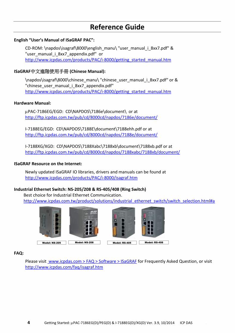
Industrial Ethernet Switch: NS-205/208 & RS-405/408 (Ring Switch)
Best choice for Industrial Ethernet Communication. http://www.icpdas.com.tw/product/solutions/industrial_ethernet_switch/switch_selection.html#a
FAQ:
Please visit www.icpdas.com > FAQ > Software > ISaGRAF for Frequently Asked Question, or visit http://www.icpdas.com/faq/isagraf.htm
Model: RS-405 Model: RS-408 Model: NS-205 Model: NS-208
.Getting Started: PAC-7186EG(D)/PEG(D) & I-7188EG(D)/XG(D) Ver. 3.9, 10/2014 ICP DAS .5
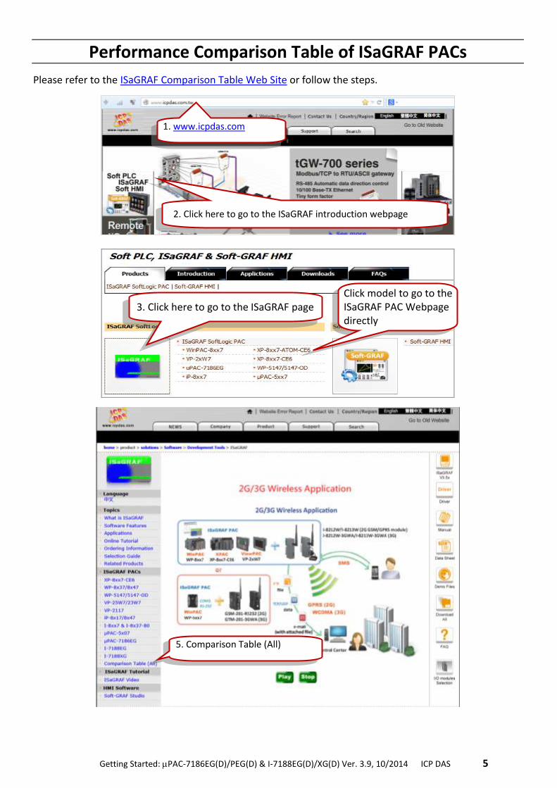
Performance Comparison Table of ISaGRAF PACs
Please refer to the ISaGRAF Comparison Table Web Site or follow the steps.
5. Comparison Table (All)
1. www.icpdas.com
2. Click here to go to the ISaGRAF introduction webpage
3. Click here to go to the ISaGRAF page Click model to go to the ISaGRAF PAC Webpage directly
6 . Getting Started: PAC-7186EG(D)/PEG(D) & I-7188EG(D)/XG(D) Ver. 3.9, 10/2014 ICP DAS ..
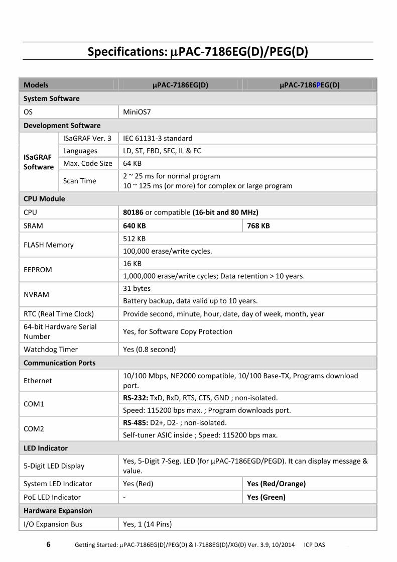
Specifications: PAC-7186EG(D)/PEG(D)
Models μPAC-7186EG(D) μPAC-7186PEG(D)
System Software
OS MiniOS7
Development Software
ISaGRAF Software
ISaGRAF Ver. 3 IEC 61131-3 standard
Languages LD, ST, FBD, SFC, IL & FC
Max. Code Size 64 KB
Scan Time 2 ~ 25 ms for normal program 10 ~ 125 ms (or more) for complex or large program
CPU Module
CPU 80186 or compatible (16-bit and 80 MHz)
SRAM 640 KB 768 KB
FLASH Memory 512 KB
100,000 erase/write cycles.
EEPROM 16 KB
1,000,000 erase/write cycles; Data retention > 10 years.
NVRAM 31 bytes
Battery backup, data valid up to 10 years.
RTC (Real Time Clock) Provide second, minute, hour, date, day of week, month, year
64-bit Hardware Serial Number
Yes, for Software Copy Protection
Watchdog Timer Yes (0.8 second)
Communication Ports
Ethernet 10/100 Mbps, NE2000 compatible, 10/100 Base-TX, Programs download port.
COM1 RS-232: TxD, RxD, RTS, CTS, GND ; non-isolated.
Speed: 115200 bps max. ; Program downloads port.
COM2 RS-485: D2+, D2- ; non-isolated.
Self-tuner ASIC inside ; Speed: 115200 bps max.
LED Indicator
5-Digit LED Display Yes, 5-Digit 7-Seg. LED (for μPAC-7186EGD/PEGD). It can display message & value.
System LED Indicator Yes (Red) Yes (Red/Orange)
PoE LED Indicator - Yes (Green)
Hardware Expansion
I/O Expansion Bus Yes, 1 (14 Pins)
.Getting Started: PAC-7186EG(D)/PEG(D) & I-7188EG(D)/XG(D) Ver. 3.9, 10/2014 ICP DAS .7
Mechanical
Dimensions (W x L x H) 72 mm x 123 mm x 35 mm
Environmental
Operating Temperature -25 ~ +75 °C
Storage Temperature -40 ~ +80 °C
Ambient Relative Humidity 5 ~ 90 % RH (non-condensing)
Power
Input Range +10 ~ +30 VDC +12 ~ +48 VDC
Protection Power reverse polarity protection
PoE - IEEE 802.3af, Class 1
Power Consumption 1.5 W for μPAC-7186EG/PEG 2.5 W for μPAC-7186EGD/PEGD (when I/O slots are empty)
Protocols (some protocols need optional devices)
NET ID User-assigned by software, 1 ~ 255
Modbus RTU/ASCII Master Protocol
Up to 2 COM Ports: COM1 ~ COM3 (*). (To connect to other Modbus Slave I/O devices) Max. Mbus_xxx Function Block amount: 128.
Modbus RTU Slave Protocol
Up to 2 COM Ports: COM1, one of COM2 or COM3 (*). (For connecting ISaGRAF, PC/HMI/OPC Server & MMI panels)
Modbus TCP/IP Protocol
Ethernet port supports Modbus TCP/IP Slave protocol for connecting ISaGRAF & PC/HMI. Max. 6 connections.
User-defined Protocol COM1, COM2 & COM3 ~ COM8 (*) by serial communication function blocks.
Remote I/O One of COM2 or COM3: RS-485 (*) supports I-7000 I/O modules & (I-87Kn or RU-87Pn + I-87K High Profile I/O boards) as Remote I/O. Max. 64 I/O module for one PAC.
Fbus Built-in COM2 Port to exchange data between ICP DAS's ISaGRAF PACs.
Ebus To exchange data between ICP DAS's ISaGRAF Ethernet PACs via Ethernet port.
SMS: Short Message Service
One of COM1 or COM3 or COM4 (*) can link to a GSM modem to support SMS. User can request data/control the controller by cellular phone. The controller can also send data & alarms to user's cellular phone. Optional GSM modems: GTM-201-RS232 ( 850/900/1800/1900 GSM/GPRS External Modem)
Send Email
Send email to maximum 10 receivers each time via internet. If applying with an X607/608 X-board, it could send email with one attached file and the maximum file size is about 488 KB for using X608 or about 112 KB for using X607.
Modem Link Supports PC to remotely download & monitor the controller through COM4 of X504.
8 . Getting Started: PAC-7186EG(D)/PEG(D) & I-7188EG(D)/XG(D) Ver. 3.9, 10/2014 ICP DAS ..
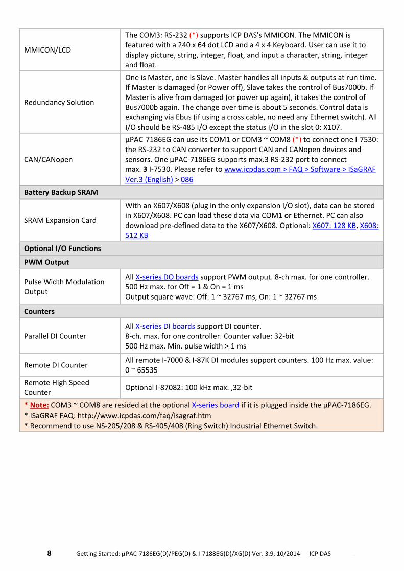
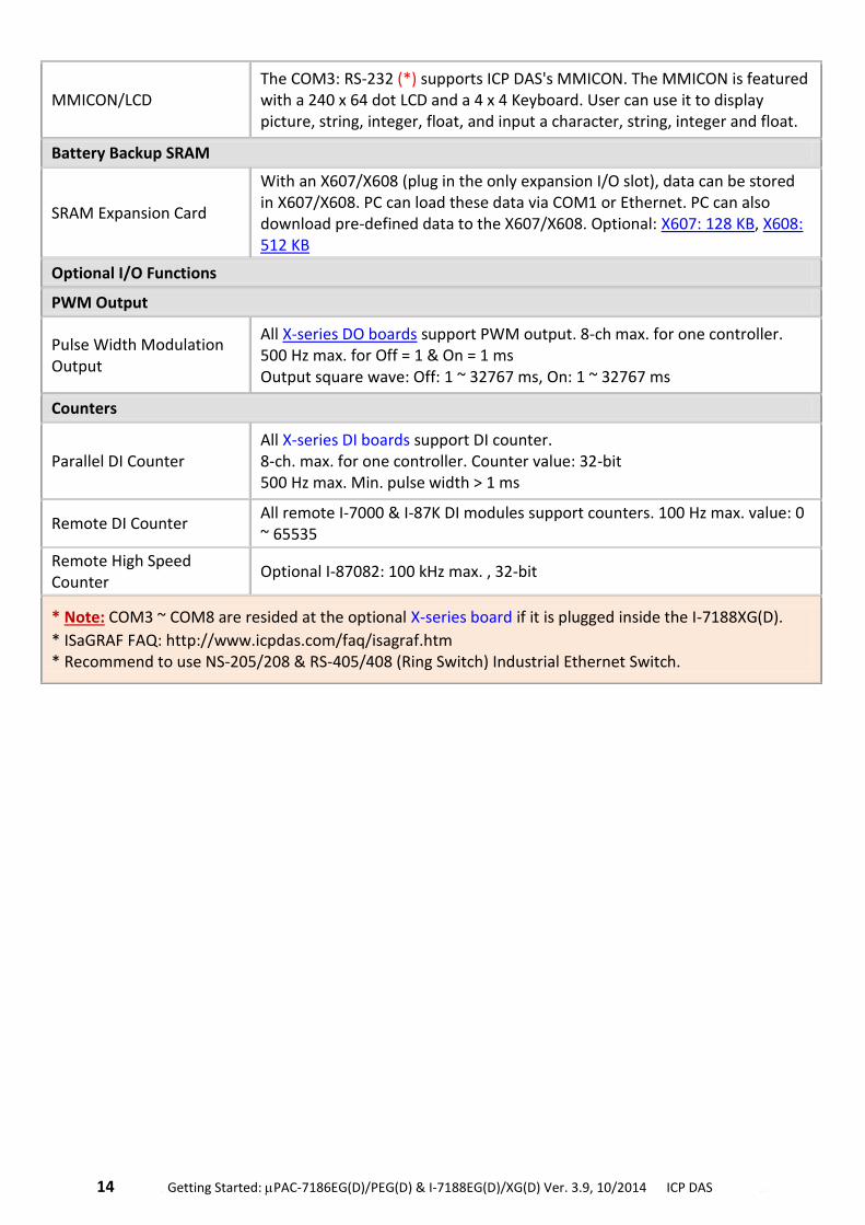
MMICON/LCD
The COM3: RS-232 (*) supports ICP DAS's MMICON. The MMICON is featured with a 240 x 64 dot LCD and a 4 x 4 Keyboard. User can use it to display picture, string, integer, float, and input a character, string, integer and float.
Redundancy Solution
One is Master, one is Slave. Master handles all inputs & outputs at run time. If Master is damaged (or Power off), Slave takes the control of Bus7000b. If Master is alive from damaged (or power up again), it takes the control of Bus7000b again. The change over time is about 5 seconds. Control data is exchanging via Ebus (if using a cross cable, no need any Ethernet switch). All I/O should be RS-485 I/O except the status I/O in the slot 0: X107.
CAN/CANopen
μPAC-7186EG can use its COM1 or COM3 ~ COM8 (*) to connect one I-7530: the RS-232 to CAN converter to support CAN and CANopen devices and sensors. One μPAC-7186EG supports max.3 RS-232 port to connect max. 3 I-7530. Please refer to www.icpdas.com > FAQ > Software > ISaGRAF Ver.3 (English) > 086
Battery Backup SRAM
SRAM Expansion Card
With an X607/X608 (plug in the only expansion I/O slot), data can be stored in X607/X608. PC can load these data via COM1 or Ethernet. PC can also download pre-defined data to the X607/X608. Optional: X607: 128 KB, X608: 512 KB
Optional I/O Functions
PWM Output
Pulse Width Modulation Output
All X-series DO boards support PWM output. 8-ch max. for one controller. 500 Hz max. for Off = 1 & On = 1 ms Output square wave: Off: 1 ~ 32767 ms, On: 1 ~ 32767 ms
Counters
Parallel DI Counter All X-series DI boards support DI counter. 8-ch. max. for one controller. Counter value: 32-bit 500 Hz max. Min. pulse width > 1 ms
Remote DI Counter All remote I-7000 & I-87K DI modules support counters. 100 Hz max. value: 0 ~ 65535
Remote High Speed Counter
Optional I-87082: 100 kHz max. ,32-bit
* Note: COM3 ~ COM8 are resided at the optional X-series board if it is plugged inside the μPAC-7186EG.
* ISaGRAF FAQ: http://www.icpdas.com/faq/isagraf.htm * Recommend to use NS-205/208 & RS-405/408 (Ring Switch) Industrial Ethernet Switch.
.Getting Started: PAC-7186EG(D)/PEG(D) & I-7188EG(D)/XG(D) Ver. 3.9, 10/2014 ICP DAS .9
Specifications: I-7188EG/EGD
Models I-7188EG I-7188EGD
System Software
OS MiniOS7
Development Software
ISaGRAF Software
ISaGRAF Ver. 3
IEC 61131-3 standard
Languages LD, ST, FBD, SFC, IL & FC
Max. Code Size
64 KB
Scan Time 5 ~ 100 ms for normal program 25 ~ 500 ms (or more) for complex or large program
CPU Module
CPU 80188 or compatible (16-bit and 40 MHz)
SRAM 512 KB
FLASH Memory 512 KB
100,000 erase/write cycles.
EEPROM 2 KB
1,000,000 erase/write cycles; Data retention > 10 years.
NVRAM 31 bytes
Battery backup, data valid up to 10 years.
RTC (Real Time Clock) Provide second, minute, hour, date, day of week, month, year
64-bit Hardware Serial Number
Yes, for Software Copy Protection
Watchdog Timer Yes (0.8 second)
Communication Ports
Ethernet 10/100 Mbps, NE2000 compatible, 10/100 Base-TX, Programs download port.
COM1 RS-232: TxD, RxD, RTS, CTS, GND ; non-isolated.
Speed: 115200 bps max.; Program downloads port.
COM2 RS-485: D2+, D2- ; non-isolated.
Self-tuner ASIC inside ; Speed: 115200 bps max.
LED Indicator
5-Digit LED Display - 5-Digit 7-Seg. LED. It can display message & value.
System LED Indicator Yes
Hardware Expansion
I/O Expansion Bus Yes, 1 (14 Pins)
10 . Getting Started: PAC-7186EG(D)/PEG(D) & I-7188EG(D)/XG(D) Ver. 3.9, 10/2014 ICP DAS ..
Mechanical
Dimensions (W x L x H) 72 mm x 123 mm x 33 mm
Environmental
Operating Temperature -25 ~ +75 °C
Storage Temperature -40 ~ +80 °C
Ambient Relative Humidity
5 ~ 90 % RH (non-condensing)
Power
Input Range +10 ~ +30 VDC
Protection Power reverse polarity protection
Power Consumption 2 W (when I/O slots are empty) 3 W (when I/O slots are empty)
Protocols (some protocols need optional devices)
NET ID User-assigned by software, 1 ~ 255
Modbus RTU/ASCII Master Protocol
Up to 2 COM Ports: COM1 ~ COM3 (*). (To connect to other Modbus Slave devices) Max. Mbus_xxx Function Block amount: 64.
Modbus RTU Slave Protocol
Up to 2 COM Ports: COM1, one of COM2 or COM3 (*). (For connecting ISaGRAF, PC/HMI/OPC Server & MMI panels)
Modbus TCP/IP Protocol
Ethernet port supports Modbus TCP/IP Slave protocol for connecting ISaGRAF & PC/HMI. Max. 4 connections.
User-defined Protocol User can write his own protocol applied at COM1, COM2 & COM3 ~ COM8 (*) by serial communication function blocks.
Remote I/O One of COM2 or COM3: RS-485 (*) supports I-7000 I/O modules & (I-87Kn or RU-87Pn + I-87K High Profile I/O boards) as Remote I/O. Max. 64 I/O module for one PAC.
Fbus Built-in COM2 Port to exchange data between ICP DAS's ISaGRAF PACs.
Ebus To exchange data between ICP DAS's ISaGRAF Ethernet PACs via Ethernet port.
SMS: Short Message Service
One of COM1 or COM3 or COM4 (*) can link to a GSM modem to support SMS. User can request data/control the controller by cellular phone. The controller can also send data & alarms to user's cellular phone. Optional GSM modems: GTM-201-RS232 ( 850/900/1800/1900 GSM/GPRS External Modem)
Modem Link Supports PC to remotely download & monitor the controller through COM4 of X504.
MMICON/LCD The COM3: RS-232 (*) supports ICP DAS's MMICON. The MMICON is featured with a 240 x 64 dot LCD and a 4 x 4 Keyboard. User can use it to display picture, string, integer, float, and input a character, string, integer and float.
Battery Backup SRAM
.Getting Started: PAC-7186EG(D)/PEG(D) & I-7188EG(D)/XG(D) Ver. 3.9, 10/2014 ICP DAS .11
SRAM Expansion Card
With an X607/X608 (plug in the only expansion I/O slot), data can be stored in X607/X608. PC can load these data via COM1 or Ethernet. PC can also download pre-defined data to the X607/X608. Optional: X607: 128 KB, X608: 512 KB
Optional I/O Functions
PWM Output
Pulse Width Modulation Output
All X-series DO boards support PWM output. 8-ch max. for one controller. 500 Hz max. for Off = 1 & On = 1 ms Output square wave: Off: 1 ~ 32767 ms, On: 1 ~ 32767 ms
Counters
Parallel DI Counter
All X-series DI boards support DI counter. 8-ch. max. for one controller. Counter value: 32-bit,500 Hz max. Min. pulse
width > 1 ms
Remote DI Counter All remote I-7000 & I-87K DI modules support counters. 100 Hz max. value: 0 ~ 65535
Remote High Speed Counter
Optional I-87082: 100 kHz max. ,32-bit
* Note: COM3 ~ COM8 are resided at the optional X-series board if it is plugged inside the I-7188EG(D).
* ISaGRAF FAQ: http://www.icpdas.com/faq/isagraf.htm * Recommend to use NS-205/208 & RS-405/408 (Ring Switch) Industrial Ethernet Switch.
12 . Getting Started: PAC-7186EG(D)/PEG(D) & I-7188EG(D)/XG(D) Ver. 3.9, 10/2014 ICP DAS ..
Specifications: I-7188XG/XGD
Models I-7188XG I-7188XGD
System Software
OS MiniOS7
Development Software
ISaGRAF Software
ISaGRAF Ver. 3
IEC 61131-3 standard
Languages LD, ST, FBD, SFC, IL & FC
Max. Code Size
64 KB
Scan Time 5 ~ 100 ms for normal program 25 ~ 500 ms (or more) for complex or large program
CPU Module
CPU 80188 or compatible (16-bit and 40 MHz)
SRAM 512 KB
FLASH Memory 512 KB
100,000 erase/write cycles.
EEPROM 2 KB
1,000,000 erase/write cycles; Data retention > 10 years.
NVRAM 31 bytes
Battery backup, data valid up to 10 years.
RTC (Real Time Clock) Provide second, minute, hour, date, day of week, month, year
64-bit Hardware Serial Number
Yes, for Software Copy Protection
Watchdog Timer Yes (0.8 second)
Communication Ports
COM1
RS-232/RS-485: RS-232: TxD, RxD, RTS, CTS, GND RS-485: D1+, D1- (Self-tuner ASIC inside)
Non-isolated ; Speed: 115200 bps max. ; Program downloads port.
COM2 RS-485: D2+, D2- (Self-tuner ASIC inside)
Non-isolated ; Speed: 115200 bps max.
Digital Input
Channels 1
Contact Dry
On Voltage Level Connect to GND
Off Voltage Level Open
Digital Output
.Getting Started: PAC-7186EG(D)/PEG(D) & I-7188EG(D)/XG(D) Ver. 3.9, 10/2014 ICP DAS .13
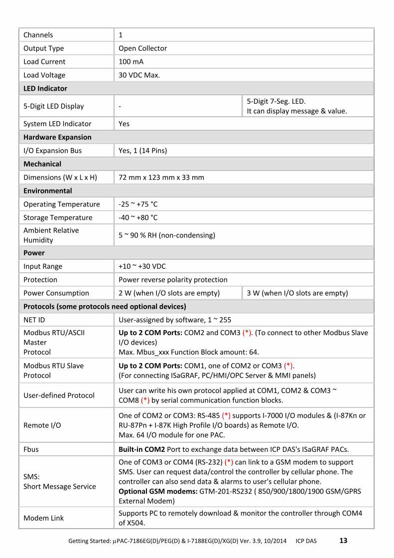
Channels 1
Output Type Open Collector
Load Current 100 mA
Load Voltage 30 VDC Max.
LED Indicator
5-Digit LED Display - 5-Digit 7-Seg. LED. It can display message & value.
System LED Indicator Yes
Hardware Expansion
I/O Expansion Bus Yes, 1 (14 Pins)
Mechanical
Dimensions (W x L x H) 72 mm x 123 mm x 33 mm
Environmental
Operating Temperature -25 ~ +75 °C
Storage Temperature -40 ~ +80 °C
Ambient Relative Humidity
5 ~ 90 % RH (non-condensing)
Power
Input Range +10 ~ +30 VDC
Protection Power reverse polarity protection
Power Consumption 2 W (when I/O slots are empty) 3 W (when I/O slots are empty)
Protocols (some protocols need optional devices)
NET ID User-assigned by software, 1 ~ 255
Modbus RTU/ASCII Master Protocol
Up to 2 COM Ports: COM2 and COM3 (*). (To connect to other Modbus Slave I/O devices) Max. Mbus_xxx Function Block amount: 64.
Modbus RTU Slave Protocol
Up to 2 COM Ports: COM1, one of COM2 or COM3 (*). (For connecting ISaGRAF, PC/HMI/OPC Server & MMI panels)
User-defined Protocol User can write his own protocol applied at COM1, COM2 & COM3 ~ COM8 (*) by serial communication function blocks.
Remote I/O One of COM2 or COM3: RS-485 (*) supports I-7000 I/O modules & (I-87Kn or RU-87Pn + I-87K High Profile I/O boards) as Remote I/O. Max. 64 I/O module for one PAC.
Fbus Built-in COM2 Port to exchange data between ICP DAS's ISaGRAF PACs.
SMS: Short Message Service
One of COM3 or COM4 (RS-232) (*) can link to a GSM modem to support SMS. User can request data/control the controller by cellular phone. The controller can also send data & alarms to user's cellular phone. Optional GSM modems: GTM-201-RS232 ( 850/900/1800/1900 GSM/GPRS External Modem)
Modem Link Supports PC to remotely download & monitor the controller through COM4 of X504.
14 . Getting Started: PAC-7186EG(D)/PEG(D) & I-7188EG(D)/XG(D) Ver. 3.9, 10/2014 ICP DAS ..
MMICON/LCD The COM3: RS-232 (*) supports ICP DAS's MMICON. The MMICON is featured with a 240 x 64 dot LCD and a 4 x 4 Keyboard. User can use it to display picture, string, integer, float, and input a character, string, integer and float.
Battery Backup SRAM
SRAM Expansion Card
With an X607/X608 (plug in the only expansion I/O slot), data can be stored in X607/X608. PC can load these data via COM1 or Ethernet. PC can also download pre-defined data to the X607/X608. Optional: X607: 128 KB, X608: 512 KB
Optional I/O Functions
PWM Output
Pulse Width Modulation Output
All X-series DO boards support PWM output. 8-ch max. for one controller. 500 Hz max. for Off = 1 & On = 1 ms Output square wave: Off: 1 ~ 32767 ms, On: 1 ~ 32767 ms
Counters
Parallel DI Counter All X-series DI boards support DI counter. 8-ch. max. for one controller. Counter value: 32-bit 500 Hz max. Min. pulse width > 1 ms
Remote DI Counter All remote I-7000 & I-87K DI modules support counters. 100 Hz max. value: 0 ~ 65535
Remote High Speed Counter
Optional I-87082: 100 kHz max. , 32-bit
* Note: COM3 ~ COM8 are resided at the optional X-series board if it is plugged inside the I-7188XG(D).
* ISaGRAF FAQ: http://www.icpdas.com/faq/isagraf.htm * Recommend to use NS-205/208 & RS-405/408 (Ring Switch) Industrial Ethernet Switch.
.Getting Started: PAC-7186EG(D)/PEG(D) & I-7188EG(D)/XG(D) Ver. 3.9, 10/2014 ICP DAS .1-1
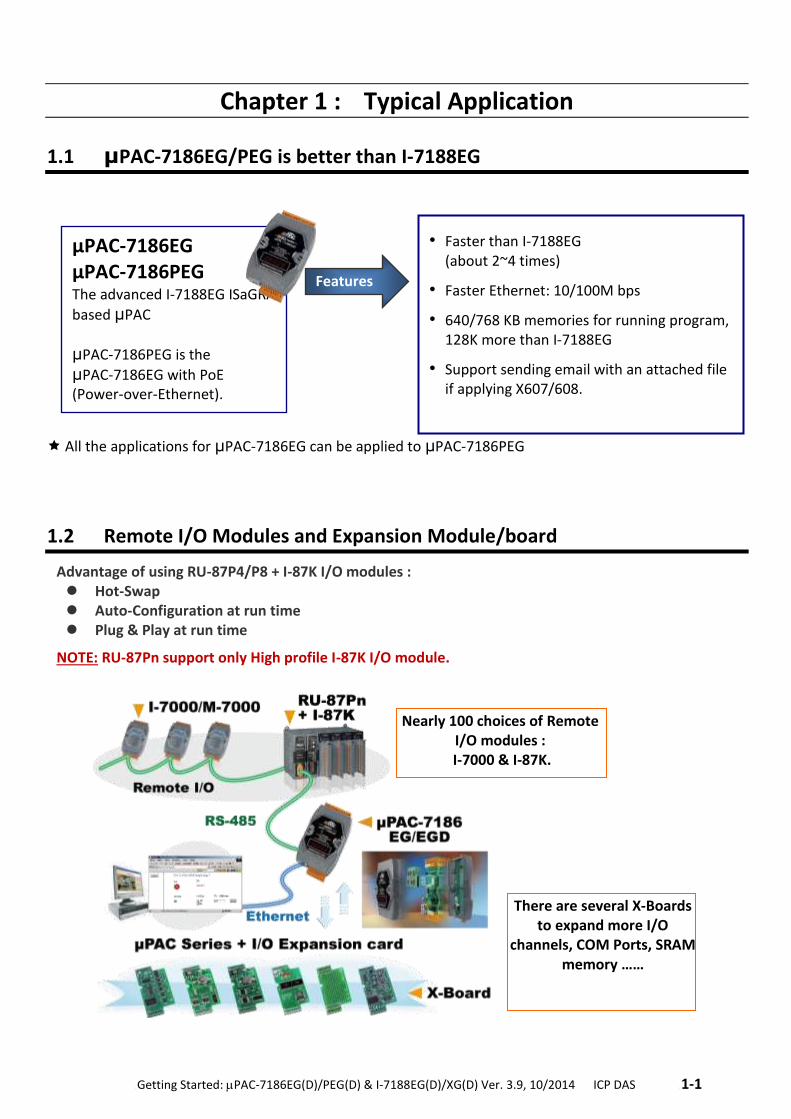
Chapter 1 : Typical Application
1.1 μPAC-7186EG/PEG is better than I-7188EG
All the applications for μPAC-7186EG can be applied to μPAC-7186PEG
1.2 Remote I/O Modules and Expansion Module/board
Advantage of using RU-87P4/P8 + I-87K I/O modules : Hot-Swap Auto-Configuration at run time Plug & Play at run time
NOTE: RU-87Pn support only High profile I-87K I/O module.
• Faster than I-7188EG (about 2~4 times)
• Faster Ethernet: 10/100M bps
• 640/768 KB memories for running program, 128K more than I-7188EG
• Support sending email with an attached file if applying X607/608.
Features
μPAC-7186EG μPAC-7186PEG The advanced I-7188EG ISaGRAF
based μPAC
μPAC-7186PEG is the
μPAC-7186EG with PoE (Power-over-Ethernet).
There are several X-Boards to expand more I/O
channels, COM Ports, SRAM memory ……
Nearly 100 choices of Remote I/O modules :
I-7000 & I-87K.
1-2 . Getting Started: PAC-7186EG(D)/PEG(D) & I-7188EG(D)/XG(D) Ver. 3.9, 10/2014 ICP DAS ..
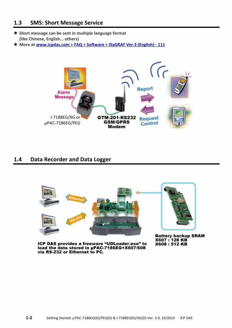
1.3 SMS: Short Message Service
Short message can be sent in multiple language format (like Chinese, English... others)
More at www.icpdas.com > FAQ > Software > ISaGRAF Ver.3 (English) - 111
1.4 Data Recorder and Data Logger
I-7188EG/XG or μPAC-7186EG/PEG
.Getting Started: PAC-7186EG(D)/PEG(D) & I-7188EG(D)/XG(D) Ver. 3.9, 10/2014 ICP DAS .1-3
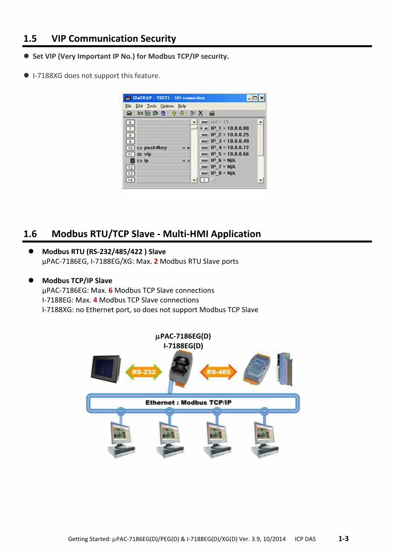
1.5 VIP Communication Security
Set VIP (Very Important IP No.) for Modbus TCP/IP security.
I-7188XG does not support this feature.
1.6 Modbus RTU/TCP Slave - Multi-HMI Application
Modbus RTU (RS-232/485/422 ) Slave μPAC-7186EG, I-7188EG/XG: Max. 2 Modbus RTU Slave ports
Modbus TCP/IP Slave
μPAC-7186EG: Max. 6 Modbus TCP Slave connections I-7188EG: Max. 4 Modbus TCP Slave connections I-7188XG: no Ethernet port, so does not support Modbus TCP Slave
PAC-7186EG(D) I-7188EG(D)
1-4 . Getting Started: PAC-7186EG(D)/PEG(D) & I-7188EG(D)/XG(D) Ver. 3.9, 10/2014 ICP DAS ..
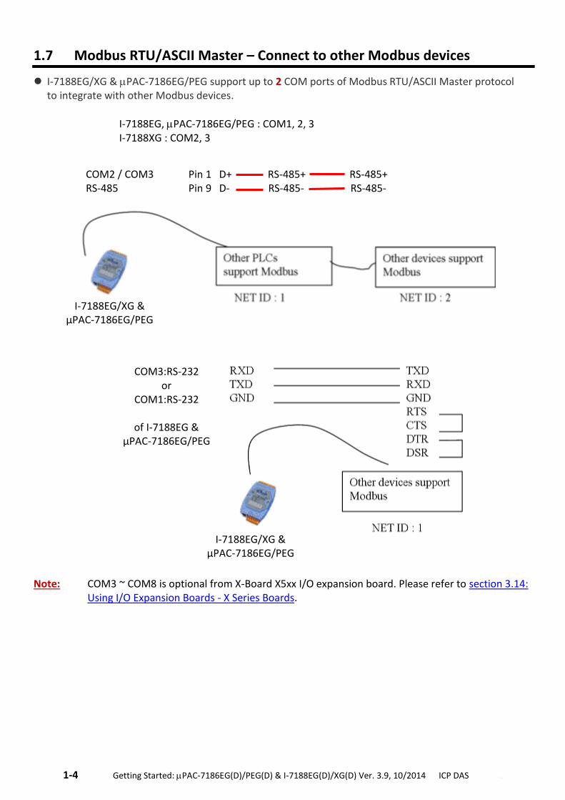
1.7 Modbus RTU/ASCII Master – Connect to other Modbus devices
I-7188EG/XG & PAC-7186EG/PEG support up to 2 COM ports of Modbus RTU/ASCII Master protocol to integrate with other Modbus devices.
I-7188EG, PAC-7186EG/PEG : COM1, 2, 3 I-7188XG : COM2, 3
Note: COM3 ~ COM8 is optional from X-Board X5xx I/O expansion board. Please refer to section 3.14:
Using I/O Expansion Boards - X Series Boards.
I-7188EG/XG & μPAC-7186EG/PEG
COM2 / COM3 Pin 1 D+ RS-485+ RS-485+ RS-485 Pin 9 D- RS-485- RS-485-
I-7188EG/XG & μPAC-7186EG/PEG
COM3:RS-232 or
COM1:RS-232
of I-7188EG & μPAC-7186EG/PEG
.Getting Started: PAC-7186EG(D)/PEG(D) & I-7188EG(D)/XG(D) Ver. 3.9, 10/2014 ICP DAS .1-5
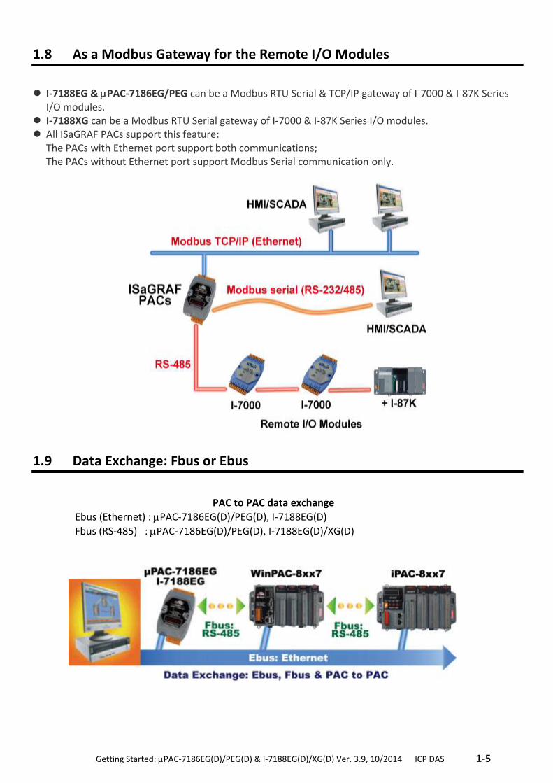
1.8 As a Modbus Gateway for the Remote I/O Modules
I-7188EG & PAC-7186EG/PEG can be a Modbus RTU Serial & TCP/IP gateway of I-7000 & I-87K Series I/O modules.
I-7188XG can be a Modbus RTU Serial gateway of I-7000 & I-87K Series I/O modules. All ISaGRAF PACs support this feature:
The PACs with Ethernet port support both communications; The PACs without Ethernet port support Modbus Serial communication only.
1.9 Data Exchange: Fbus or Ebus
PAC to PAC data exchange
Ebus (Ethernet) : PAC-7186EG(D)/PEG(D), I-7188EG(D)
Fbus (RS-485) : PAC-7186EG(D)/PEG(D), I-7188EG(D)/XG(D)
1-6 . Getting Started: PAC-7186EG(D)/PEG(D) & I-7188EG(D)/XG(D) Ver. 3.9, 10/2014 ICP DAS ..
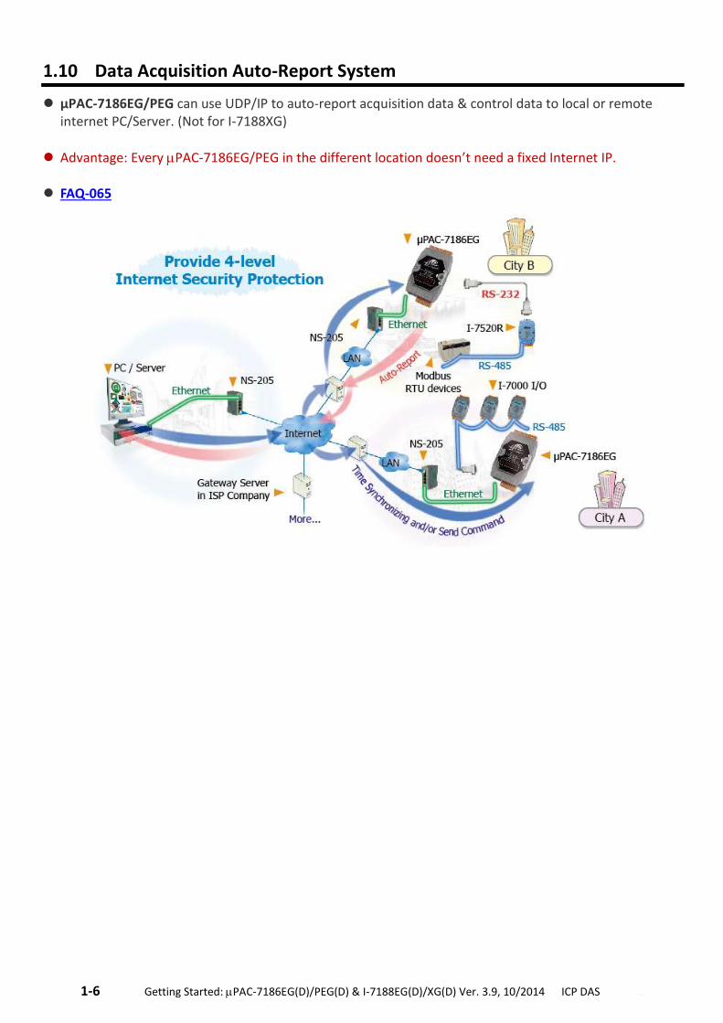
1.10 Data Acquisition Auto-Report System
μPAC-7186EG/PEG can use UDP/IP to auto-report acquisition data & control data to local or remote internet PC/Server. (Not for I-7188XG)
Advantage: Every PAC-7186EG/PEG in the different location doesn’t need a fixed Internet IP.
FAQ-065
.Getting Started: PAC-7186EG(D)/PEG(D) & I-7188EG(D)/XG(D) Ver. 3.9, 10/2014 ICP DAS .1-7
1.11 PAC-7186EG can send email with one attached file
ISaGRAF PAC can send Email with one attached file via Ethernet Port. The maximum file size is about 488K bytes. (X607: 112K bytes; X608: 488K bytes)
One Email can send to 10 receivers at one sending. (FAQ-067 & FAQ-077)
1-8 . Getting Started: PAC-7186EG(D)/PEG(D) & I-7188EG(D)/XG(D) Ver. 3.9, 10/2014 ICP DAS ..
1.12 An Easy Way to Program the FRnet I/O Modules
Advantage of FRnet I/O: Fast I/O scan time is about 3 ms/scan. (It depends on your program’s PLC scan time. Ex: If the ISaGRAF program’s PLC scan time is about 9 ms, then the scan time for all will be 9 ms, not 3 ms)
Note: FRnet I/O do not support AI & AO yet. Refer to FAQ-082
1.13 Integrate with CAN/CANopen Devices and Sensors
PAC-7186EG Supports max. 3 I-7530 (RS-232 to CAN) Converters. Refer to www.icpdas.com > FAQ > Software > ISaGRAF Ver.3 (English) - 086
.Getting Started: PAC-7186EG(D)/PEG(D) & I-7188EG(D)/XG(D) Ver. 3.9, 10/2014 ICP DAS .1-9
1.14 GPS applications: ISaGRAF PAC plus I-87211W or GPS-721
μPAC-7186(P)EG, WP-8xx7, VP-2xW7/4xx7, iP-8xx7 can support one I-87211W (slot 0~7) or I-87211W / GPS-721 as RS-485 remote GPS I/O.
For doing auto-time-synchronization and getting local Longitude and Latitude
Please refer to FAQ-107
More GPS receivers at www.icpdas.com > Products > Wireless..... > GPS receiver
1-10 . Getting Started: PAC-7186EG(D)/PEG(D) & I-7188EG(D)/XG(D) Ver. 3.9, 10/2014 ICP DAS ..
1.15 ZigBee Wireless Solution
ISaGRAF PAC plus ZB-2550P and ZB-2551P converters (ZigBee to RS-232/485) Please refer to FAQ-110
.Getting Started: PAC-7186EG(D)/PEG(D) & I-7188EG(D)/XG(D) Ver. 3.9, 10/2014 ICP DAS .1-11
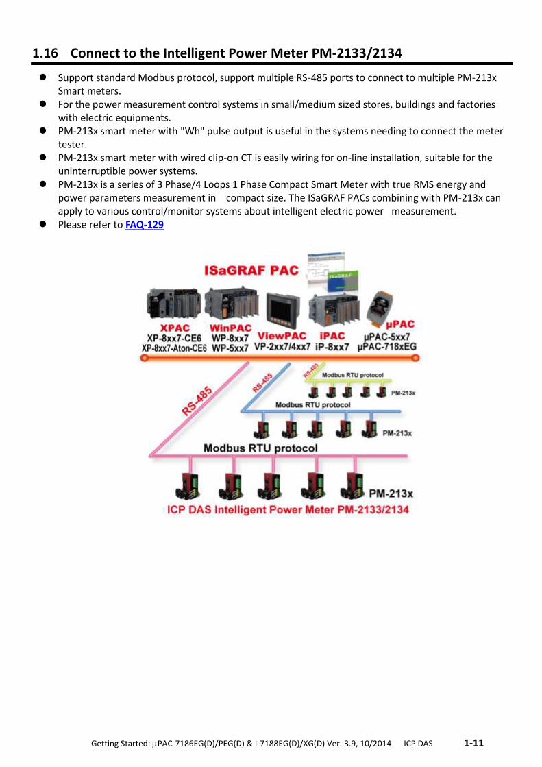
1.16 Connect to the Intelligent Power Meter PM-2133/2134
Support standard Modbus protocol, support multiple RS-485 ports to connect to multiple PM-213x Smart meters.
For the power measurement control systems in small/medium sized stores, buildings and factories with electric equipments.
PM-213x smart meter with "Wh" pulse output is useful in the systems needing to connect the meter tester.
PM-213x smart meter with wired clip-on CT is easily wiring for on-line installation, suitable for the uninterruptible power systems.
PM-213x is a series of 3 Phase/4 Loops 1 Phase Compact Smart Meter with true RMS energy and power parameters measurement in compact size. The ISaGRAF PACs combining with PM-213x can apply to various control/monitor systems about intelligent electric power measurement.
Please refer to FAQ-129
1-12 . Getting Started: PAC-7186EG(D)/PEG(D) & I-7188EG(D)/XG(D) Ver. 3.9, 10/2014 ICP DAS ..
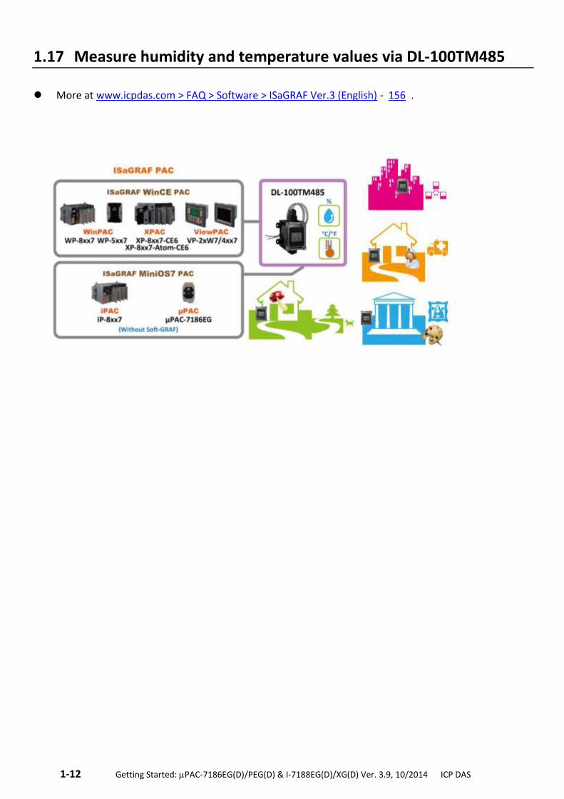
1.17 Measure humidity and temperature values via DL-100TM485
More at www.icpdas.com > FAQ > Software > ISaGRAF Ver.3 (English) - 156 .
.Getting Started: PAC-7186EG(D)/PEG(D) & I-7188EG(D)/XG(D) Ver. 3.9, 10/2014 ICP DAS .2-1
Chapter 2 : Software Installing & Programming
Note: For detailed English User’s Manual please refer to “ISaGRAF User’s Manual” or CD of \napdos\isagraf\8000\english_manu\ "user_manual_i_8xx7.pdf” & "user_manual_i_8xx7_appendix.pdf” or http://www.icpdas.com/products/PAC/i-8000/getting_started_manual.htm
2.1 Step 1 – Installing the ISaGRAF Software
The user needs to install the following two kinds of software before he can program the ISaGRAF controller system. They are A. ISaGRAF Workbench B. ICP DAS Utilities for ISaGRAF
User has to purchase at least one pcs. of ISaGRAF Workbench (Ver. 3.4x or Ver. 3.5x ISaGRAF-256-E or ISaGRAF-256-C or ISaGRAF-32-E or ISaGRAF-32-C) to install on his PC to edit, download, monitor & debug the controller system. Item (B) is free and it is burned inside the CD-ROM which is delivered with the PAC.
Operating System Requirements:
One of the following computer operating systems must be installed on the target computer before you install the ISaGRAF Workbench software program:
Windows 95 / Windows 98 / Windows 2000 Windows NT Version 3.51 or Windows NT Version 4.0 Windows XP or Vista or Windows 7 (Please refer to FAQ-117)
Steps to Install the ISaGRAF Workbench: If your PC OS is Windows Vista or Windows 7 (32-bit), refer to 2.1.4. If your PC OS is Windows 7 (64-bit), please refer to 2.1.5.
1. Insert the ISaGRAF Workbench CD into your CD-ROM drive. If your computer does not auto-start the installation, use the Windows Explorer and go to the CD-ROM drive where the Workbench CD is installed.
2. Double-click on the "install.bat" file listed on the ISaGRAF CD. If the "install.bat" file is not found on your ISaGRAF CD, then double-click on the "ISaGRAF.exe" file to start the installation process.
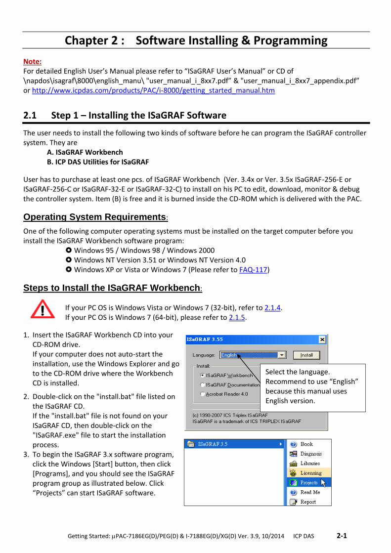
3. To begin the ISaGRAF 3.x software program, click the Windows [Start] button, then click [Programs], and you should see the ISaGRAF program group as illustrated below. Click “Projects” can start ISaGRAF software.
Select the language. Recommend to use “English” because this manual uses English version.
2-2 . Getting Started: PAC-7186EG(D)/PEG(D) & I-7188EG(D)/XG(D) Ver. 3.9, 10/2014 ICP DAS ..
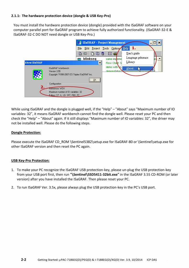
2.1.1: The hardware protection device (dongle & USB Key-Pro) You must install the hardware protection device (dongle) provided with the ISaGRAF software on your computer parallel port for ISaGRAF program to achieve fully authorized functionality. (ISaGRAF-32-E & ISaGRAF-32-C DO NOT need dongle or USB Key-Pro.)
While using ISaGRAF and the dongle is plugged well, if the “Help” – “About” says “Maximum number of IO variables: 32”, it means ISaGRAF workbench cannot find the dongle well. Please reset your PC and then check the “Help” – “About” again. If it still displays “Maximum number of IO variables: 32”, the driver may not be installed well. Please do the following steps. Dongle Protection: Please execute the ISaGRAF CD_ROM \Sentinel5382\setup.exe for ISaGRAF-80 or \Sentinel\setup.exe for other ISaGRAF version and then reset the PC again. USB Key-Pro Protection: 1. To make your PC recognize the ISaGRAF USB protection-key, please un-plug the USB protection-key
from your USB port first, then run “\Sentinel\SSD5411-32bit.exe” in the ISaGRAF 3.55 CD-ROM (or later version) after you have installed the ISaGRAF. Then please reset your PC.
2. To run ISaGRAF Ver. 3.5x, please always plug the USB protection-key in the PC’s USB port.
1.
2.
.Getting Started: PAC-7186EG(D)/PEG(D) & I-7188EG(D)/XG(D) Ver. 3.9, 10/2014 ICP DAS .2-3
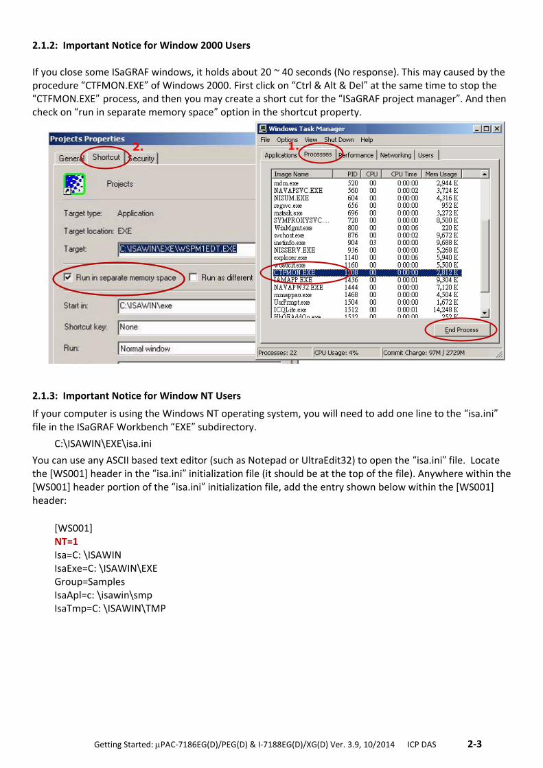
2.1.2: Important Notice for Window 2000 Users If you close some ISaGRAF windows, it holds about 20 ~ 40 seconds (No response). This may caused by the procedure “CTFMON.EXE” of Windows 2000. First click on “Ctrl & Alt & Del” at the same time to stop the “CTFMON.EXE” process, and then you may create a short cut for the “ISaGRAF project manager”. And then check on “run in separate memory space” option in the shortcut property.
2.1.3: Important Notice for Window NT Users
If your computer is using the Windows NT operating system, you will need to add one line to the “isa.ini” file in the ISaGRAF Workbench “EXE” subdirectory.
C:\ISAWIN\EXE\isa.ini
You can use any ASCII based text editor (such as Notepad or UltraEdit32) to open the “isa.ini” file. Locate the [WS001] header in the “isa.ini” initialization file (it should be at the top of the file). Anywhere within the [WS001] header portion of the “isa.ini” initialization file, add the entry shown below within the [WS001] header:
[WS001] NT=1 Isa=C: \ISAWIN IsaExe=C: \ISAWIN\EXE Group=Samples IsaApl=c: \isawin\smp IsaTmp=C: \ISAWIN\TMP
2. 1.
2-4 . Getting Started: PAC-7186EG(D)/PEG(D) & I-7188EG(D)/XG(D) Ver. 3.9, 10/2014 ICP DAS ..
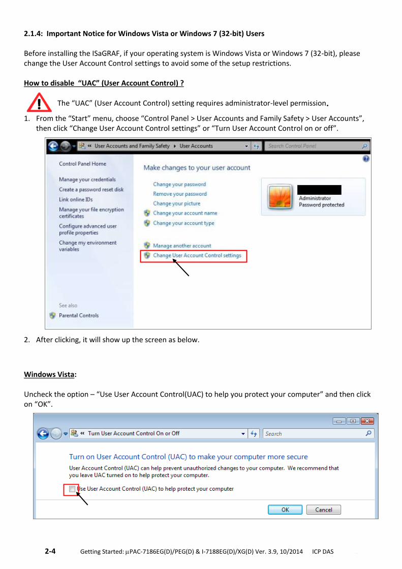
2.1.4: Important Notice for Windows Vista or Windows 7 (32-bit) Users Before installing the ISaGRAF, if your operating system is Windows Vista or Windows 7 (32-bit), please change the User Account Control settings to avoid some of the setup restrictions. How to disable “UAC” (User Account Control) ?
The “UAC” (User Account Control) setting requires administrator-level permission.
1. From the “Start” menu, choose “Control Panel > User Accounts and Family Safety > User Accounts”, then click “Change User Account Control settings” or “Turn User Account Control on or off”.
2. After clicking, it will show up the screen as below.
Windows Vista: Uncheck the option – “Use User Account Control(UAC) to help you protect your computer” and then click on “OK”.
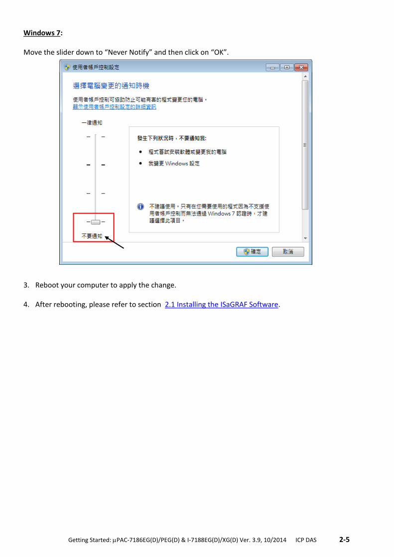
.Getting Started: PAC-7186EG(D)/PEG(D) & I-7188EG(D)/XG(D) Ver. 3.9, 10/2014 ICP DAS .2-5
Windows 7: Move the slider down to “Never Notify” and then click on “OK”. 3. Reboot your computer to apply the change.
4. After rebooting, please refer to section 2.1 Installing the ISaGRAF Software.
2-6 . Getting Started: PAC-7186EG(D)/PEG(D) & I-7188EG(D)/XG(D) Ver. 3.9, 10/2014 ICP DAS ..
2.1.5: Important Notice for Windows 7 (64-bit) Users
Because the ISaGRAF Workbench can only be installed on a 32-bit version of Windows operating system, users can use the following ways to create a proper installation environment for the ISaGRAF Workbench 3.55. If using Windows XP Mode that can be installed on 64-bit version of Windows 7 Professional, Enterprise, and Ultimate editions. If using VMware Workstation/Player that can be installed on any 64-bit version of Windows OS (e.g., Windows 7 or Windows 8).
Installing the Virtual PC and XP Mode:
1. Download Windows Virtual PC and Windows XP Mode installers from the Windows Virtual PC Web site
(http://go.microsoft.com/fwlink/?LinkID=160479)
2. Double-click on "WindowsXPMode_nn-NN.exe” (where nn-NN is the locale, e.g. en-US) and follow the
instructions in the wizard to install Windows XP Mode.
3. Double-click on "Windows6.1-KB958559-x64.msu” to install Windows Virtual PC。
4. Reboot your computer.
5. After rebooting, click on "Star > All Programs > Windows Virtual PC” and then click Windows XP Mode.
6. Follow the instructions in the wizard to complete Windows XP Mode Setup and Configuration. Record
the password that is provided during the Setup because it is required to log on to your virtual machine.
7. Now, go back to section 2.1 to install the ISaGRAF.
Using VMware Workstation/Player:
1. Download and install VMware Workstation 10 (trail version) on VMware website. https://my.vmware.com/web/vmware/info/slug/desktop_end_user_computing/vmware_workstation/10_0
2. Create a virtual machine running Windows XP (32-bit, SP3).
3. Install ISaGRAF Workbench 3.55 on a virtual machine.
4. Install ISaGRAF I/O Library on a virtual machine.
5. The related settings for a virtual machine.
6. Install USB dongle driver on a virtual machine. More at www.icpdas.com > Support > FAQ > ISaGRAF Soft-Logic PAC > FAQ-174
2.1.6: Important Setting for Using Variable Arrays Important setting for using variable arrays:
Please add two lines on the top of the c:\isawin\ese\isa.ini file to enable the usage of variable arrays. [DEBUG] Arrays=1
.Getting Started: PAC-7186EG(D)/PEG(D) & I-7188EG(D)/XG(D) Ver. 3.9, 10/2014 ICP DAS .2-7
2.2 Step 2 – Installing ICP DAS Utilities For ISaGRAF
The “ICP DAS Utilities For ISaGRAF” consists of 3 major items:
I/O libraries: for I-7188EG/XG, PAC-7186EG, I-8xx7 & W-8xx7 Modem_Link utility Auto-scan I/O utility
Note: The ISaGRAF Workbench software program must be installed before attempting to install the
“ICP DAS Utilities for ISaGRAF”. If you have not installed the ISaGRAF Workbench program,
please refer to Section 2.1 Step 1 before continuing.
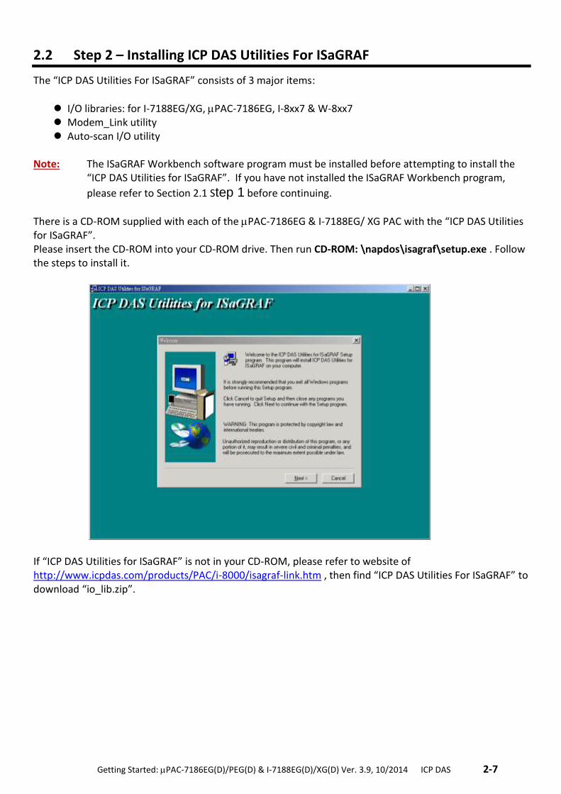
There is a CD-ROM supplied with each of the PAC-7186EG & I-7188EG/ XG PAC with the “ICP DAS Utilities for ISaGRAF”. Please insert the CD-ROM into your CD-ROM drive. Then run CD-ROM: \napdos\isagraf\setup.exe . Follow the steps to install it.
If “ICP DAS Utilities for ISaGRAF” is not in your CD-ROM, please refer to website of http://www.icpdas.com/products/PAC/i-8000/isagraf-link.htm , then find “ICP DAS Utilities For ISaGRAF” to download “io_lib.zip”.
2-8 . Getting Started: PAC-7186EG(D)/PEG(D) & I-7188EG(D)/XG(D) Ver. 3.9, 10/2014 ICP DAS ..
2.3 Step 3 – Writing A Simple ISaGRAF Program
Note: Please refer to “User’s Manual of ISaGRAF PAC” or CD of \napdos\isagraf\8000\english_manu\ "user_manual_i_8xx7.pdf” for detailed English User’s Manual.
EXAMPLE OF LD PROGRAM: The following is a step-by-step example on how to create a ladder logic (hence forth referred as "LD")
program using the ISaGRAF Workbench software program provided with the I-7188EG/XG & PAC-7186EG (plugged X-board: X107) controller system. Variables Used In the Example LD Program:
Name Type Attribute Description
SW1 Boolean Input Input Switch1
SW2 Boolean Input Input Switch2
SHUT Boolean Input Input Shutdown button
OUT01 Boolean Output Output1
OUT02 Boolean Output Output2
OUT03 Boolean Output Output3
TMR1 Timer Internal Time Period of blinking, initial value is set at "T#1s"
Ladder Logic Program Outline:
Process Operation Actions:
1. Monitor/Control SW1 (default: OFF) & SW2 (default: OFF) two Switches. 2. Monitor/Control SHUT button (default: OFF, normal close) 3. If either SW1 or SW2 is ON, and SHUT is OFF, active "Blink" Timer TMR1 4. OUT01~03 will ON and OFF at one second Interval Rate 5. Push SHUT to stop the blinking of OUT01~03.
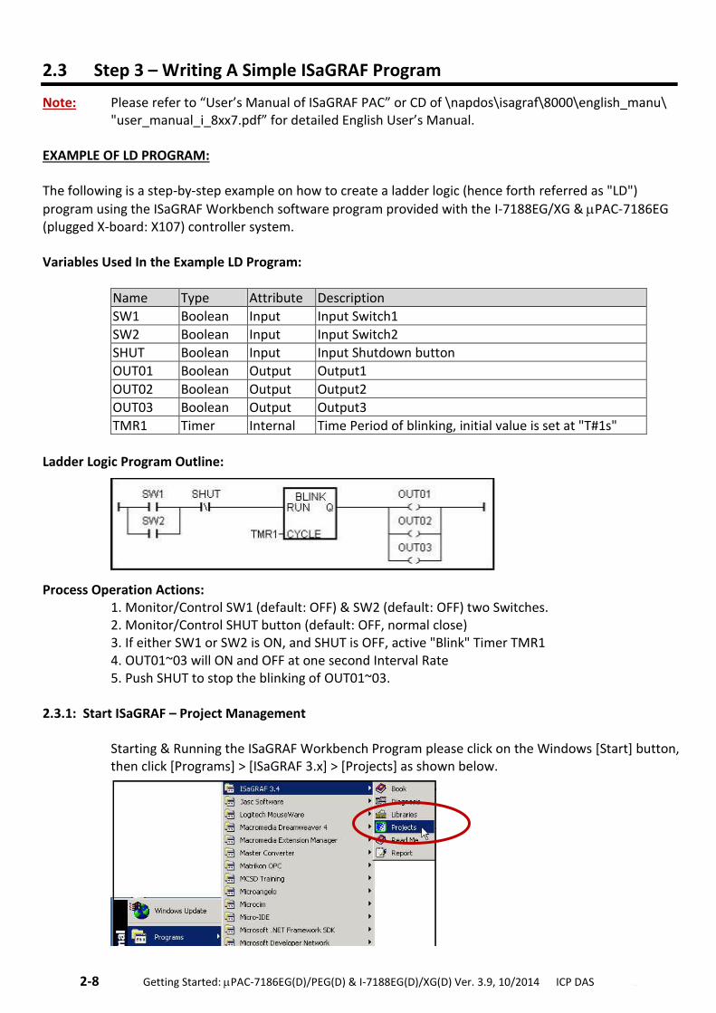
2.3.1: Start ISaGRAF – Project Management Starting & Running the ISaGRAF Workbench Program please click on the Windows [Start] button, then click [Programs] > [ISaGRAF 3.x] > [Projects] as shown below.
.Getting Started: PAC-7186EG(D)/PEG(D) & I-7188EG(D)/XG(D) Ver. 3.9, 10/2014 ICP DAS .2-9
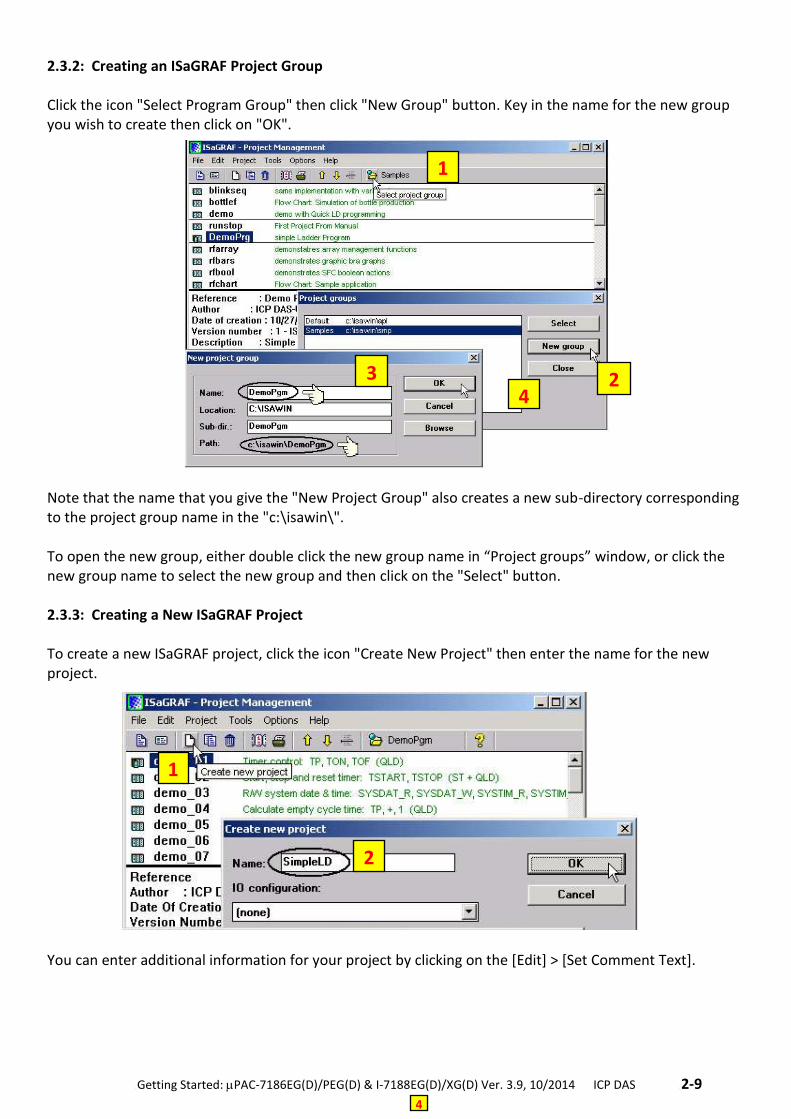
2.3.2: Creating an ISaGRAF Project Group Click the icon "Select Program Group" then click "New Group" button. Key in the name for the new group you wish to create then click on "OK".
Note that the name that you give the "New Project Group" also creates a new sub-directory corresponding to the project group name in the "c:\isawin\". To open the new group, either double click the new group name in “Project groups” window, or click the new group name to select the new group and then click on the "Select" button. 2.3.3: Creating a New ISaGRAF Project To create a new ISaGRAF project, click the icon "Create New Project" then enter the name for the new project.
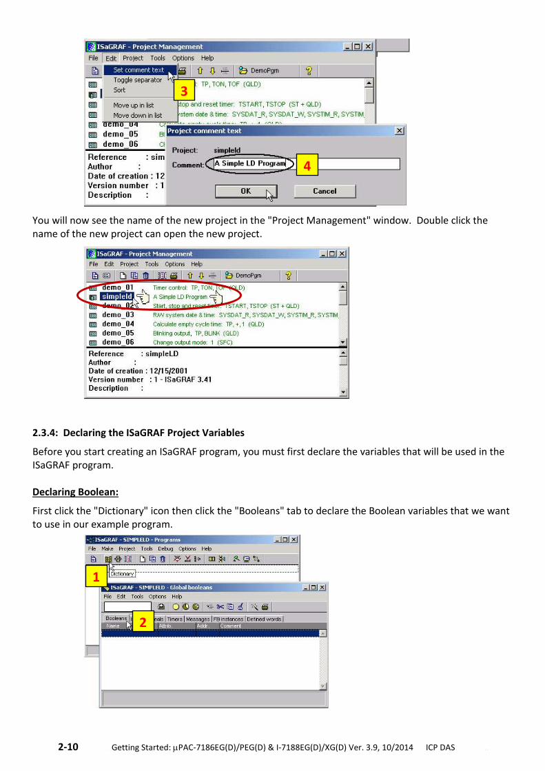
You can enter additional information for your project by clicking on the [Edit] > [Set Comment Text].
1
4
2 3 4
1
2
2-10 . Getting Started: PAC-7186EG(D)/PEG(D) & I-7188EG(D)/XG(D) Ver. 3.9, 10/2014 ICP DAS ..
You will now see the name of the new project in the "Project Management" window. Double click the name of the new project can open the new project.
2.3.4: Declaring the ISaGRAF Project Variables
Before you start creating an ISaGRAF program, you must first declare the variables that will be used in the ISaGRAF program. Declaring Boolean:
First click the "Dictionary" icon then click the "Booleans" tab to declare the Boolean variables that we want to use in our example program.
3
4
1
2
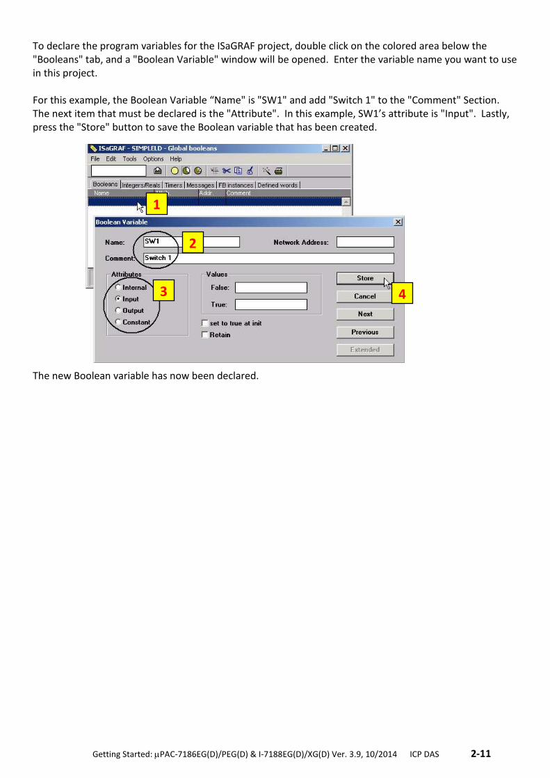
.Getting Started: PAC-7186EG(D)/PEG(D) & I-7188EG(D)/XG(D) Ver. 3.9, 10/2014 ICP DAS .2-11
To declare the program variables for the ISaGRAF project, double click on the colored area below the "Booleans" tab, and a "Boolean Variable" window will be opened. Enter the variable name you want to use in this project. For this example, the Boolean Variable “Name" is "SW1" and add "Switch 1" to the "Comment" Section. The next item that must be declared is the "Attribute". In this example, SW1’s attribute is "Input". Lastly, press the "Store" button to save the Boolean variable that has been created.
The new Boolean variable has now been declared.
1
2
3 4
2-12 . Getting Started: PAC-7186EG(D)/PEG(D) & I-7188EG(D)/XG(D) Ver. 3.9, 10/2014 ICP DAS ..
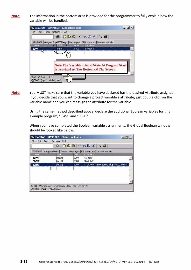
Note: The information in the bottom area is provided for the programmer to fully explain how the variable will be handled.
Note: You MUST make sure that the variable you have declared has the desired Attribute assigned. If you decide that you want to change a project variable’s attribute, just double click on the variable name and you can reassign the attribute for the variable. Using the same method described above, declare the additional Boolean variables for this example program, "SW2" and "SHUT". When you have completed the Boolean variable assignments, the Global Boolean window should be looked like below.
.Getting Started: PAC-7186EG(D)/PEG(D) & I-7188EG(D)/XG(D) Ver. 3.9, 10/2014 ICP DAS .2-13
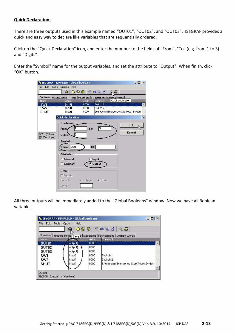
Quick Declaration: There are three outputs used in this example named “OUT01”, “OUT02”, and “OUT03”. ISaGRAF provides a quick and easy way to declare like variables that are sequentially ordered. Click on the "Quick Declaration" icon, and enter the number to the fields of “From”, "To" (e.g. from 1 to 3) and “Digits”. Enter the "Symbol" name for the output variables, and set the attribute to "Output". When finish, click “OK” button.
All three outputs will be immediately added to the "Global Booleans" window. Now we have all Boolean variables.
2-14 . Getting Started: PAC-7186EG(D)/PEG(D) & I-7188EG(D)/XG(D) Ver. 3.9, 10/2014 ICP DAS ..
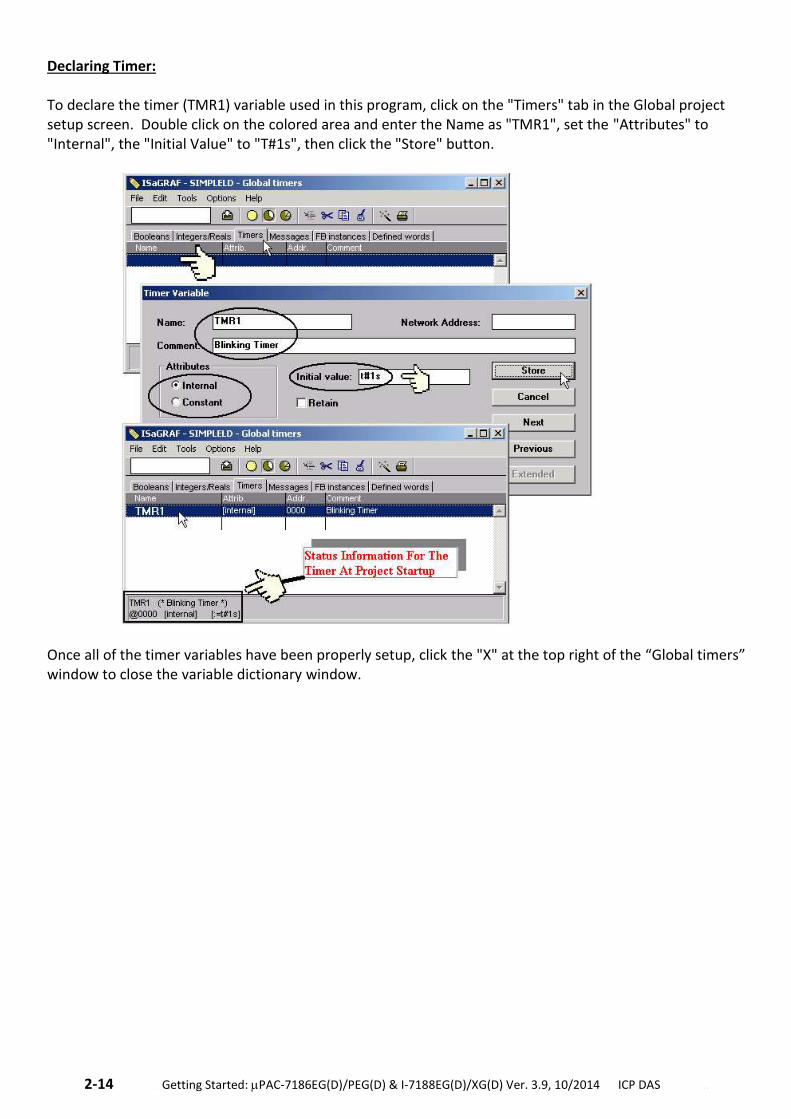
Declaring Timer: To declare the timer (TMR1) variable used in this program, click on the "Timers" tab in the Global project setup screen. Double click on the colored area and enter the Name as "TMR1", set the "Attributes" to "Internal", the "Initial Value" to "T#1s", then click the "Store" button.
Once all of the timer variables have been properly setup, click the "X" at the top right of the “Global timers” window to close the variable dictionary window.
.Getting Started: PAC-7186EG(D)/PEG(D) & I-7188EG(D)/XG(D) Ver. 3.9, 10/2014 ICP DAS .2-15
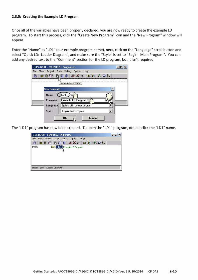
2.3.5: Creating the Example LD Program
Once all of the variables have been properly declared, you are now ready to create the example LD program. To start this process, click the "Create New Program" icon and the "New Program" window will appear. Enter the "Name" as "LD1" (our example program name), next, click on the "Language" scroll button and select "Quick LD: Ladder Diagram", and make sure the "Style" is set to "Begin: Main Program". You can add any desired text to the "Comment" section for the LD program, but it isn’t required.
The "LD1" program has now been created. To open the "LD1" program, double click the "LD1" name.
2-16 . Getting Started: PAC-7186EG(D)/PEG(D) & I-7188EG(D)/XG(D) Ver. 3.9, 10/2014 ICP DAS ..
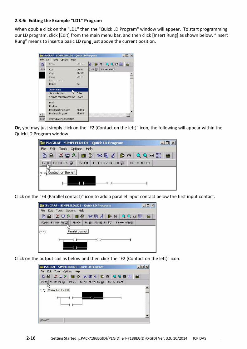
2.3.6: Editing the Example "LD1" Program
When double click on the "LD1" then the "Quick LD Program" window will appear. To start programming our LD program, click [Edit] from the main menu bar, and then click [Insert Rung] as shown below. “Insert Rung” means to insert a basic LD rung just above the current position.
Or, you may just simply click on the "F2 (Contact on the left)” icon, the following will appear within the Quick LD Program window.
Click on the "F4 (Parallel contact)" icon to add a parallel input contact below the first input contact.
Click on the output coil as below and then click the "F2 (Contact on the left)" icon.
.Getting Started: PAC-7186EG(D)/PEG(D) & I-7188EG(D)/XG(D) Ver. 3.9, 10/2014 ICP DAS .2-17
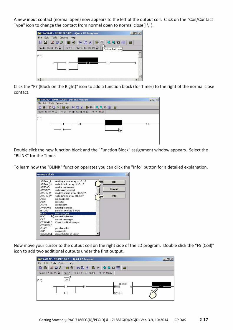
A new input contact (normal open) now appears to the left of the output coil. Click on the "Coil/Contact Type" icon to change the contact from normal open to normal close(|\|).
Click the "F7 (Block on the Right)" icon to add a function block (for Timer) to the right of the normal close contact.
Double click the new function block and the "Function Block" assignment window appears. Select the "BLINK" for the Timer. To learn how the "BLINK" function operates you can click the "Info" button for a detailed explanation.
Now move your cursor to the output coil on the right side of the LD program. Double click the “F5 (Coil)” icon to add two additional outputs under the first output.
2-18 . Getting Started: PAC-7186EG(D)/PEG(D) & I-7188EG(D)/XG(D) Ver. 3.9, 10/2014 ICP DAS ..
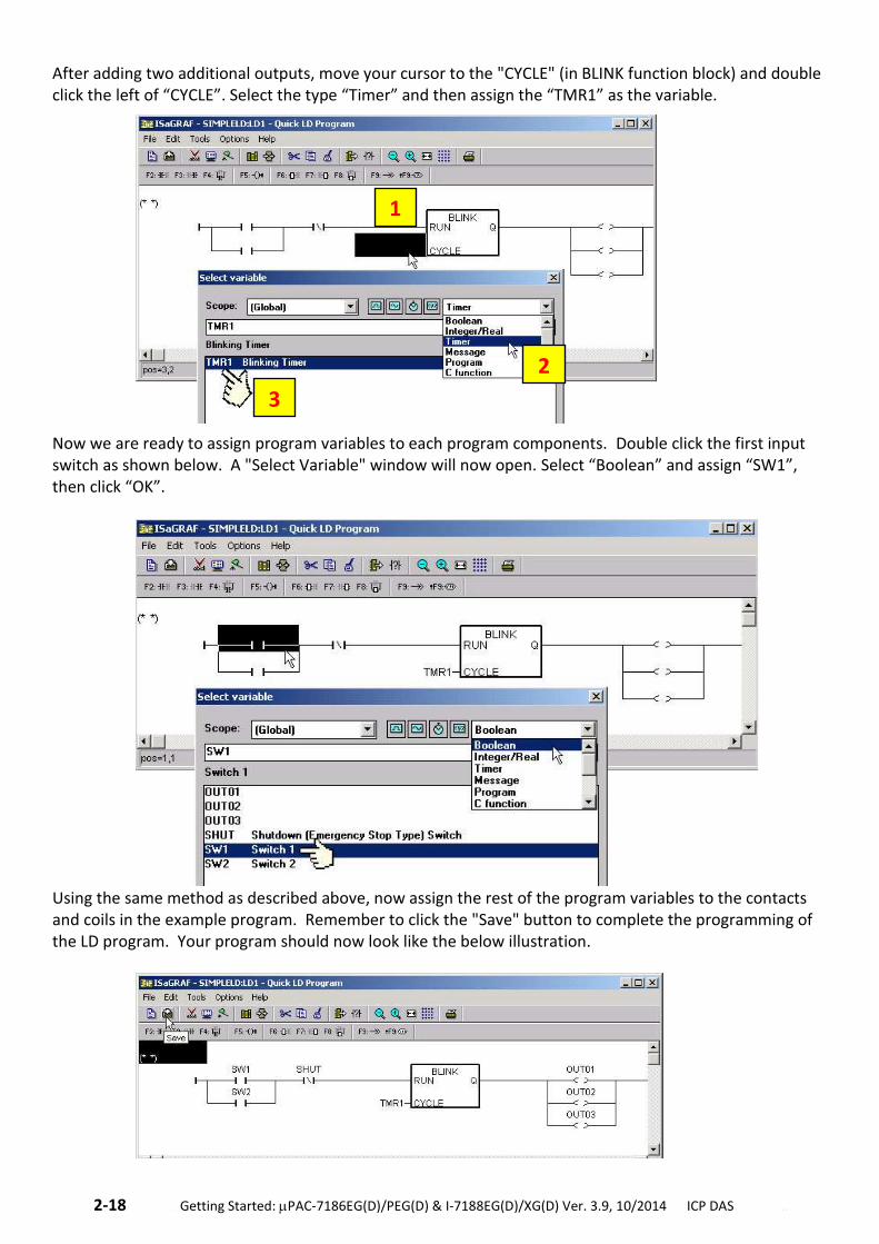
After adding two additional outputs, move your cursor to the "CYCLE" (in BLINK function block) and double click the left of “CYCLE”. Select the type “Timer” and then assign the “TMR1” as the variable.
Now we are ready to assign program variables to each program components. Double click the first input switch as shown below. A "Select Variable" window will now open. Select “Boolean” and assign “SW1”, then click “OK”.
Using the same method as described above, now assign the rest of the program variables to the contacts and coils in the example program. Remember to click the "Save" button to complete the programming of the LD program. Your program should now look like the below illustration.
1
2
3
.Getting Started: PAC-7186EG(D)/PEG(D) & I-7188EG(D)/XG(D) Ver. 3.9, 10/2014 ICP DAS .2-19
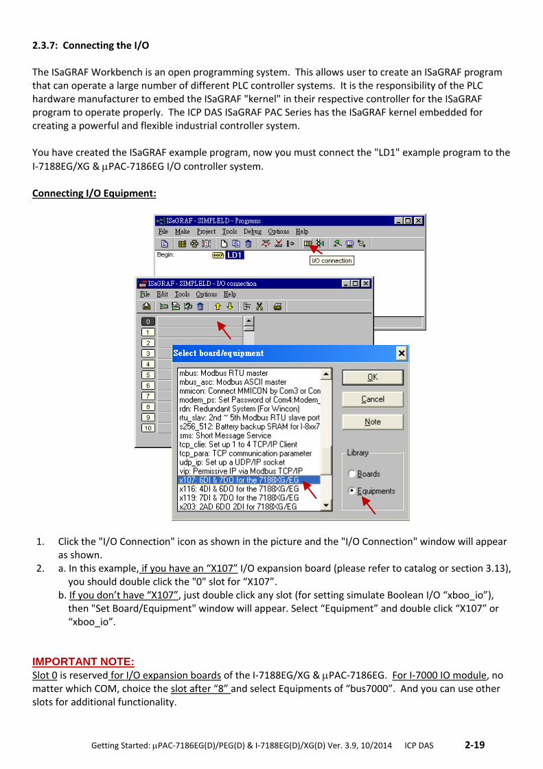
2.3.7: Connecting the I/O The ISaGRAF Workbench is an open programming system. This allows user to create an ISaGRAF program that can operate a large number of different PLC controller systems. It is the responsibility of the PLC hardware manufacturer to embed the ISaGRAF "kernel" in their respective controller for the ISaGRAF program to operate properly. The ICP DAS ISaGRAF PAC Series has the ISaGRAF kernel embedded for creating a powerful and flexible industrial controller system. You have created the ISaGRAF example program, now you must connect the "LD1" example program to the
I-7188EG/XG & PAC-7186EG I/O controller system. Connecting I/O Equipment:
1. Click the "I/O Connection" icon as shown in the picture and the "I/O Connection" window will appear as shown.
2. a. In this example, if you have an “X107” I/O expansion board (please refer to catalog or section 3.13), you should double click the "0" slot for “X107”. b. If you don’t have “X107”, just double click any slot (for setting simulate Boolean I/O “xboo_io”), then "Set Board/Equipment" window will appear. Select “Equipment” and double click “X107” or “xboo_io”.
IMPORTANT NOTE: Slot 0 is reserved for I/O expansion boards of the I-7188EG/XG & PAC-7186EG. For I-7000 IO module, no matter which COM, choice the slot after “8” and select Equipments of “bus7000”. And you can use other slots for additional functionality.
2-20 . Getting Started: PAC-7186EG(D)/PEG(D) & I-7188EG(D)/XG(D) Ver. 3.9, 10/2014 ICP DAS ..
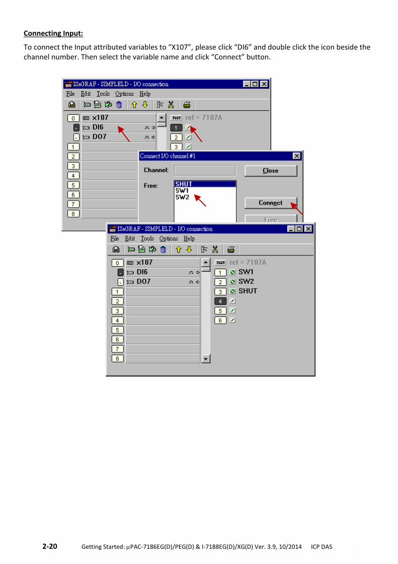
Connecting Input:
To connect the Input attributed variables to “X107”, please click “DI6” and double click the icon beside the channel number. Then select the variable name and click “Connect” button.
.Getting Started: PAC-7186EG(D)/PEG(D) & I-7188EG(D)/XG(D) Ver. 3.9, 10/2014 ICP DAS .2-21
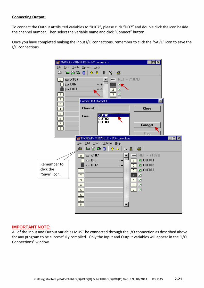
Connecting Output: To connect the Output attributed variables to “X107”, please click “DO7” and double click the icon beside the channel number. Then select the variable name and click “Connect” button. Once you have completed making the input I/O connections, remember to click the "SAVE" icon to save the I/O connections.
IMPORTANT NOTE: All of the Input and Output variables MUST be connected through the I/O connection as described above for any program to be successfully compiled. Only the Input and Output variables will appear in the "I/O Connections" window.
Remember to click the “Save” icon.
2-22 . Getting Started: PAC-7186EG(D)/PEG(D) & I-7188EG(D)/XG(D) Ver. 3.9, 10/2014 ICP DAS ..
2.4 Step 4 – Compiling & Simulating The Example Project
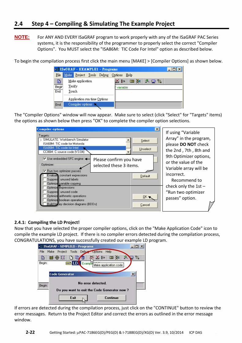
NOTE: For ANY AND EVERY ISaGRAF program to work properly with any of the ISaGRAF PAC Series systems, it is the responsibility of the programmer to properly select the correct "Compiler Options". You MUST select the "ISA86M: TIC Code For Intel" option as described below.
To begin the compilation process first click the main menu [MAKE] > [Compiler Options] as shown below. The "Compiler Options" window will now appear. Make sure to select (click "Select" for "Targets" items) the options as shown below then press "OK" to complete the compiler option selections.
2.4.1: Compiling the LD Project! Now that you have selected the proper compiler options, click on the "Make Application Code" icon to compile the example LD project. If there is no compiler errors detected during the compilation process, CONGRATULATIONS, you have successfully created our example LD program.
If errors are detected during the compilation process, just click on the "CONTINUE" button to review the error messages. Return to the Project Editor and correct the errors as outlined in the error message window.
If using “Variable Array” in the program, please DO NOT check the 2nd , 7th , 8th and 9th Optimizer options, or the value of the Variable array will be incorrect. Recommend to check only the 1st – “Run two optimizer passes” option.
Please confirm you have selected these 3 items.
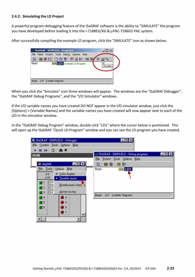
.Getting Started: PAC-7186EG(D)/PEG(D) & I-7188EG(D)/XG(D) Ver. 3.9, 10/2014 ICP DAS .2-23
2.4.2: Simulating the LD Project A powerful program-debugging feature of the ISaGRAF software is the ability to "SIMULATE" the program
you have developed before loading it into the I-7188EG/XG & PAC-7186EG PAC system. After successfully compiling the example LD program, click the "SIMULATE" icon as shown below.
When you click the "Simulate" icon three windows will appear. The windows are the "ISaGRAF Debugger", the "ISaGRAF Debug Programs", and the "I/O Simulator" windows. If the I/O variable names you have created DO NOT appear in the I/O simulator window, just click the [Options] > [Variable Names] and the variable names you have created will now appear next to each of the I/O in the simulator window. In the "ISaGRAF Debug Program" window, double click "LD1" where the cursor below is positioned. This will open up the ISaGRAF “Quick LD Program” window and you can see the LD program you have created.
2-24 . Getting Started: PAC-7186EG(D)/PEG(D) & I-7188EG(D)/XG(D) Ver. 3.9, 10/2014 ICP DAS ..
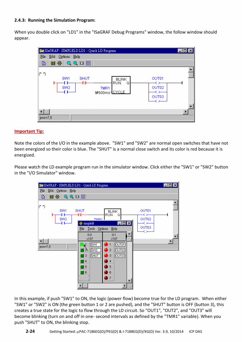
2.4.3: Running the Simulation Program: When you double click on "LD1" in the "ISaGRAF Debug Programs" window, the follow window should appear.
Important Tip: Note the colors of the I/O in the example above. "SW1" and "SW2" are normal open switches that have not been energized so their color is blue. The "SHUT" is a normal close switch and its color is red because it is energized. Please watch the LD example program run in the simulator window. Click either the "SW1" or "SW2" button in the "I/O Simulator" window.
In this example, if push "SW1" to ON, the logic (power flow) become true for the LD program. When either "SW1" or "SW2" is ON (the green button 1 or 2 are pushed), and the "SHUT" button is OFF (button 3), this creates a true state for the logic to flow through the LD circuit. So "OUT1", "OUT2", and "OUT3" will become blinking (turn on and off in one- second intervals as defined by the "TMR1" variable). When you push "SHUT" to ON, the blinking stop.
.Getting Started: PAC-7186EG(D)/PEG(D) & I-7188EG(D)/XG(D) Ver. 3.9, 10/2014 ICP DAS .2-25
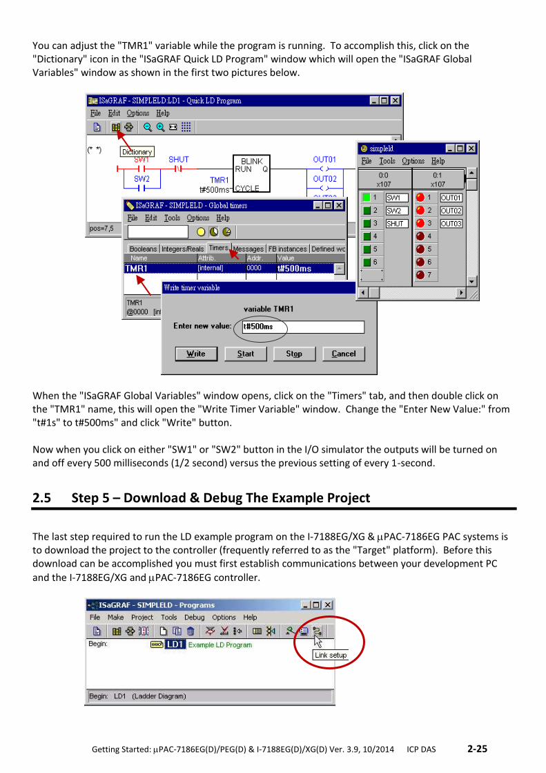
You can adjust the "TMR1" variable while the program is running. To accomplish this, click on the "Dictionary" icon in the "ISaGRAF Quick LD Program" window which will open the "ISaGRAF Global Variables" window as shown in the first two pictures below.
When the "ISaGRAF Global Variables" window opens, click on the "Timers" tab, and then double click on the "TMR1" name, this will open the "Write Timer Variable" window. Change the "Enter New Value:" from "t#1s" to t#500ms" and click "Write" button. Now when you click on either "SW1" or "SW2" button in the I/O simulator the outputs will be turned on and off every 500 milliseconds (1/2 second) versus the previous setting of every 1-second.
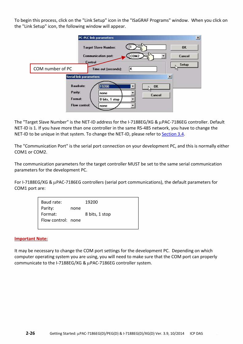
2.5 Step 5 – Download & Debug The Example Project
The last step required to run the LD example program on the I-7188EG/XG & PAC-7186EG PAC systems is to download the project to the controller (frequently referred to as the "Target" platform). Before this download can be accomplished you must first establish communications between your development PC
and the I-7188EG/XG and PAC-7186EG controller.
2-26 . Getting Started: PAC-7186EG(D)/PEG(D) & I-7188EG(D)/XG(D) Ver. 3.9, 10/2014 ICP DAS ..
To begin this process, click on the "Link Setup" icon in the "ISaGRAF Programs" window. When you click on the "Link Setup" icon, the following window will appear.
The "Target Slave Number" is the NET-ID address for the I-7188EG/XG & PAC-7186EG controller. Default NET-ID is 1. If you have more than one controller in the same RS-485 network, you have to change the NET-ID to be unique in that system. To change the NET-ID, please refer to Section 3.4. The "Communication Port" is the serial port connection on your development PC, and this is normally either COM1 or COM2. The communication parameters for the target controller MUST be set to the same serial communication parameters for the development PC.
For I-7188EG/XG & PAC-7186EG controllers (serial port communications), the default parameters for COM1 port are:
Important Note: It may be necessary to change the COM port settings for the development PC. Depending on which computer operating system you are using, you will need to make sure that the COM port can properly
communicate to the I-7188EG/XG & PAC-7186EG controller system.
Baud rate: 19200 Parity: none Format: 8 bits, 1 stop Flow control: none
COM number of PC
.Getting Started: PAC-7186EG(D)/PEG(D) & I-7188EG(D)/XG(D) Ver. 3.9, 10/2014 ICP DAS .2-27
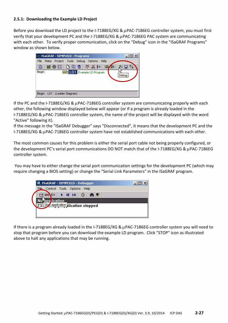
2.5.1: Downloading the Example LD Project
Before you download the LD project to the I-7188EG/XG & PAC-7186EG controller system, you must first
verify that your development PC and the I-7188EG/XG & PAC-7186EG PAC system are communicating with each other. To verify proper communication, click on the "Debug" icon in the "ISaGRAF Programs" window as shown below.
If the PC and the I-7188EG/XG & PAC-7186EG controller system are communicating properly with each other, the following window displayed below will appear (or if a program is already loaded in the
I-7188EG/XG & PAC-7186EG controller system, the name of the project will be displayed with the word "Active" following it). If the message in the "ISaGRAF Debugger" says "Disconnected", it means that the development PC and the
I-7188EG/XG & PAC-7186EG controller system have not established communications with each other. The most common causes for this problem is either the serial port cable not being properly configured, or
the development PC’s serial port communications DO NOT match that of the I-7188EG/XG & PAC-7186EG controller system. You may have to either change the serial port communication settings for the development PC (which may require changing a BIOS setting) or change the "Serial Link Parameters" in the ISaGRAF program.
If there is a program already loaded in the I-7188EG/XG & PAC-7186EG controller system you will need to stop that program before you can download the example LD program. Click "STOP" icon as illustrated above to halt any applications that may be running.
2-28 . Getting Started: PAC-7186EG(D)/PEG(D) & I-7188EG(D)/XG(D) Ver. 3.9, 10/2014 ICP DAS ..
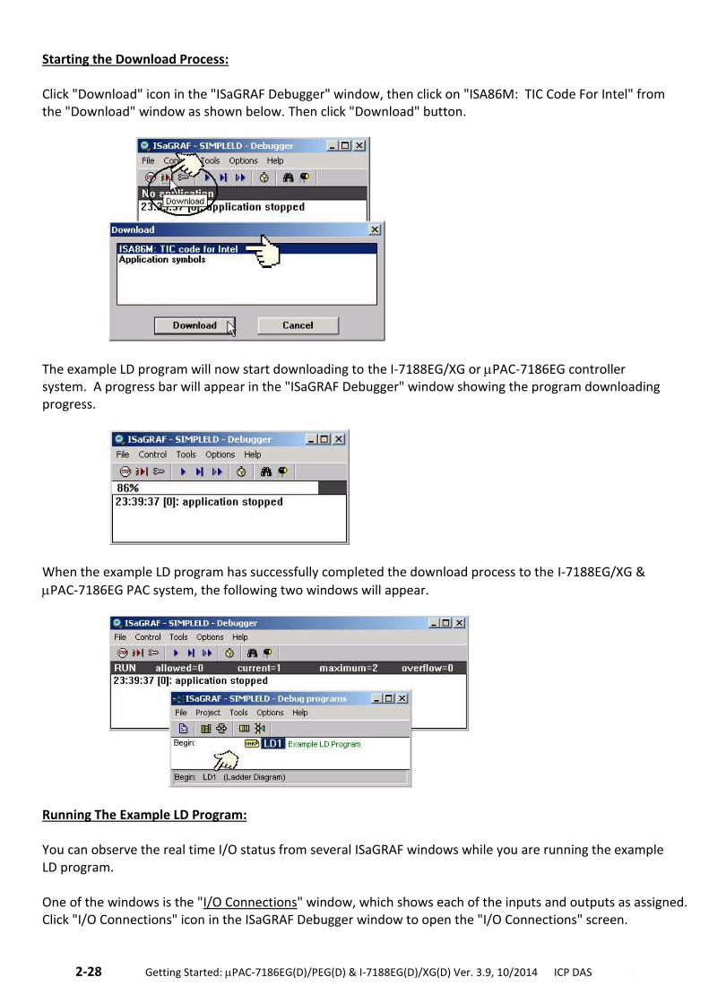
Starting the Download Process: Click "Download" icon in the "ISaGRAF Debugger" window, then click on "ISA86M: TIC Code For Intel" from the "Download" window as shown below. Then click "Download" button.
The example LD program will now start downloading to the I-7188EG/XG or PAC-7186EG controller system. A progress bar will appear in the "ISaGRAF Debugger" window showing the program downloading progress.
When the example LD program has successfully completed the download process to the I-7188EG/XG &
PAC-7186EG PAC system, the following two windows will appear.
Running The Example LD Program: You can observe the real time I/O status from several ISaGRAF windows while you are running the example LD program. One of the windows is the "I/O Connections" window, which shows each of the inputs and outputs as assigned. Click "I/O Connections" icon in the ISaGRAF Debugger window to open the "I/O Connections" screen.
.Getting Started: PAC-7186EG(D)/PEG(D) & I-7188EG(D)/XG(D) Ver. 3.9, 10/2014 ICP DAS .2-29
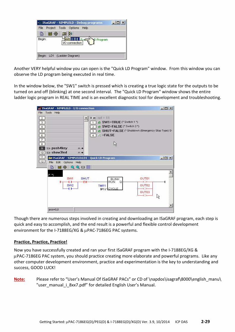
Another VERY helpful window you can open is the "Quick LD Program" window. From this window you can observe the LD program being executed in real time. In the window below, the "SW1" switch is pressed which is creating a true logic state for the outputs to be turned on and off (blinking) at one second interval. The "Quick LD Program" window shows the entire ladder logic program in REAL TIME and is an excellent diagnostic tool for development and troubleshooting.
Though there are numerous steps involved in creating and downloading an ISaGRAF program, each step is quick and easy to accomplish, and the end result is a powerful and flexible control development
environment for the I-7188EG/XG & PAC-7186EG PAC systems. Practice, Practice, Practice!
Now you have successfully created and ran your first ISaGRAF program with the I-7188EG/XG &
PAC-7186EG PAC system, you should practice creating more elaborate and powerful programs. Like any other computer development environment, practice and experimentation is the key to understanding and success, GOOD LUCK! Note: Please refer to “User’s Manual Of ISaGRAF PACs” or CD of \napdos\isagraf\8000\english_manu\
"user_manual_i_8xx7.pdf” for detailed English User’s Manual.
2-30 . Getting Started: PAC-7186EG(D)/PEG(D) & I-7188EG(D)/XG(D) Ver. 3.9, 10/2014 ICP DAS ..
2.6 ISaGRAF Demo Programs List
2.6.1: Demo Programs List I-7188EG/XG & PAC-7186EG I-8000 CD-ROM: \napdos\isagraf\7188eg\demo or ftp://ftp.icpdas.com/pub/cd/8000cd/napdos/isagraf/7188eg/demo/
Project Name Description I/O Boards Or Complex
Equipment Used
Demo_01 Receive message and echo back to COM2 or COM3 X503 / 4 / 5 / 6
Demo_02 Write one string to COM5 & COM6 for X503 X503
Demo_03 Receive message and echo back to COM6 or COM7 (Access to variables as array)
X503
Demo_04 Convert I-7000 and insert X-board to I-7188EG Bus7000b X107
Demo_05 Timer Control, TP, TON, TOF X304
Demo_06 Show a value to S-MMI, VAL10LED X304
Demo_07 Control X107 & I-7060D Relay IO Bus7000b X107
Demo_08 Receive message and echo back to COM3 and control DO for X507 / 8 / 9.
X507 / 8 / 9
Demo_09 Using S-MMI and Timer to control tStart, tStop, Reset to 0.
Demo_10 Using S-MMI X107
Demo_11 Link to other Modbus RTU devices mbus
Demo_12 Convert I-7000 and display Analog Input value to S-MMI for training box
Bus7000b
Demo_13 Convert I-7000 and display Analog Input value to S-MMI for training box
Bus7000b
Demo_18 PID control. PID_AL can not be simulated in PC, please download to controller.
Demo_21 Write one string to COM3 & COM4 Xbi8 (Virtual D/I) X50x
Demo_22 Receive message and echo back to COM3 or COM4 X50x
Demo_23 Receive a user defined protocol from PC X50x
Demo_35a Time Synchronization : 35A (used with demo 35B) Update Date & Time at this controller will synchronize date & time at 35B
Fbus_m
Demo_35b Time Synchronization : 35B(used with demo 35A) Fbus_s
Demo_36 Get driver version of I-7188EG
Demo_41 Record Alarm (text) to X607/X608 & PC can load it by "ICPDAS UDloader"
X607 / 608 Xbi8 (Virtual D/I) Xbo8 (Virtual D/O)
Demo_43 SMS demo, Please declare your own phone No. in the dictionary, message type
SMS
Demo_43a Similar to demo_43, but it can send message to 2 or more mobile phones.
SMS
Demo_44 Demo of PC to download data to the X607/X608 X607/ 608 Xbo8 (Virtual D/O)
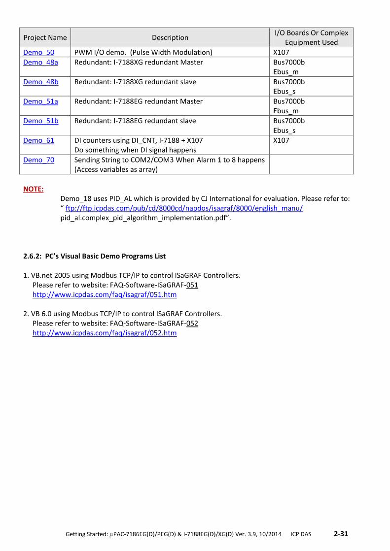
.Getting Started: PAC-7186EG(D)/PEG(D) & I-7188EG(D)/XG(D) Ver. 3.9, 10/2014 ICP DAS .2-31
Project Name Description I/O Boards Or Complex
Equipment Used
Demo_50 PWM I/O demo. (Pulse Width Modulation) X107
Demo_48a Redundant: I-7188XG redundant Master Bus7000b Ebus_m
Demo_48b Redundant: I-7188XG redundant slave Bus7000b Ebus_s
Demo_51a Redundant: I-7188EG redundant Master Bus7000b Ebus_m
Demo_51b Redundant: I-7188EG redundant slave Bus7000b Ebus_s
Demo_61 DI counters using DI_CNT, I-7188 + X107 Do something when DI signal happens
X107
Demo_70 Sending String to COM2/COM3 When Alarm 1 to 8 happens (Access variables as array)
NOTE:
Demo_18 uses PID_AL which is provided by CJ International for evaluation. Please refer to: “ ftp://ftp.icpdas.com/pub/cd/8000cd/napdos/isagraf/8000/english_manu/ pid_al.complex_pid_algorithm_implementation.pdf”.
2.6.2: PC’s Visual Basic Demo Programs List 1. VB.net 2005 using Modbus TCP/IP to control ISaGRAF Controllers.
Please refer to website: FAQ-Software-ISaGRAF-051 http://www.icpdas.com/faq/isagraf/051.htm
2. VB 6.0 using Modbus TCP/IP to control ISaGRAF Controllers. Please refer to website: FAQ-Software-ISaGRAF-052 http://www.icpdas.com/faq/isagraf/052.htm
.Getting Started: PAC-7186EG(D)/PEG(D) & I-7188EG(D)/XG(D) Ver. 3.9, 10/2014 ICP DAS .3-1
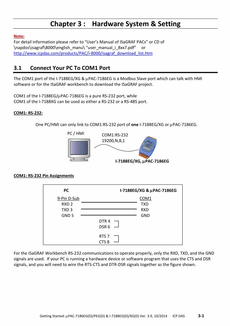
Chapter 3 : Hardware System & Setting
Note: For detail information please refer to “User’s Manual of ISaGRAF PACs” or CD of \napdos\isagraf\8000\english_manu\ "user_manual_i_8xx7.pdf” or http://www.icpdas.com/products/PAC/i-8000/isagraf_download_list.htm
3.1 Connect Your PC To COM1 Port
The COM1 port of the I-7188EG/XG & PAC-7186EG is a Modbus Slave port which can talk with HMI software or for the ISaGRAF workbench to download the ISaGRAF project.
COM1 of the I-7188EG/PAC-7186EG is a pure RS-232 port, while COM1 of the I-7188XG can be used as either a RS-232 or a RS-485 port. COM1: RS-232:
One PC/HMI can only link to COM1:RS-232 port of one I-7188EG/XG or PAC-7186EG. COM1: RS-232 Pin Assignments
For the ISaGRAF Workbench RS-232 communications to operate properly, only the RXD, TXD, and the GND signals are used. If your PC is running a hardware device or software program that uses the CTS and DSR signals, and you will need to wire the RTS-CTS and DTR-DSR signals together as the figure shown.
COM1:RS-232 19200,N,8,1
I-7188EG/XG, PAC-7186EG
PC / HMI
PC I-7188EG/XG & PAC-7186EG
9-Pin D-Sub COM1 RXD 2 TXD TXD 3 RXD GND 5 GND DTR 4 DSR 6
RTS 7 CTS 8
3-2 . Getting Started: PAC-7186EG(D)/PEG(D) & I-7188EG(D)/XG(D) Ver. 3.9, 10/2014 ICP DAS ..
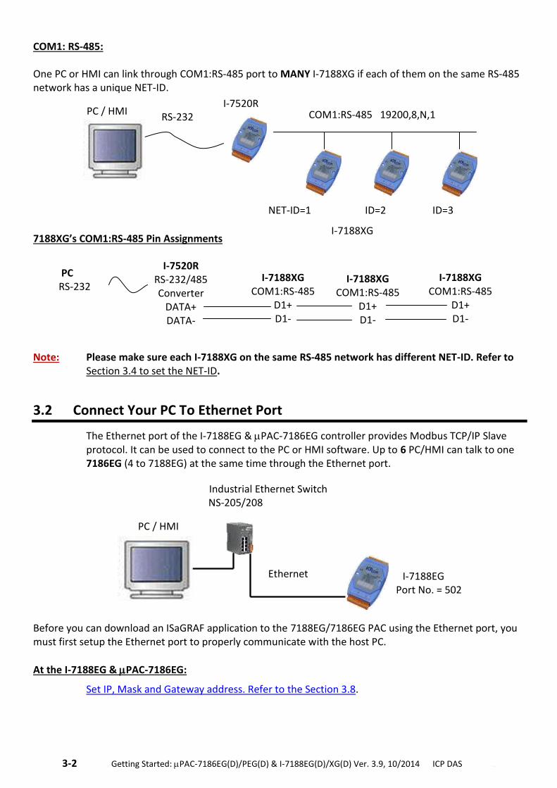
COM1: RS-485: One PC or HMI can link through COM1:RS-485 port to MANY I-7188XG if each of them on the same RS-485 network has a unique NET-ID.
7188XG’s COM1:RS-485 Pin Assignments
Note: Please make sure each I-7188XG on the same RS-485 network has different NET-ID. Refer to Section 3.4 to set the NET-ID.
3.2 Connect Your PC To Ethernet Port
The Ethernet port of the I-7188EG & PAC-7186EG controller provides Modbus TCP/IP Slave protocol. It can be used to connect to the PC or HMI software. Up to 6 PC/HMI can talk to one 7186EG (4 to 7188EG) at the same time through the Ethernet port.
Before you can download an ISaGRAF application to the 7188EG/7186EG PAC using the Ethernet port, you must first setup the Ethernet port to properly communicate with the host PC.
At the I-7188EG & PAC-7186EG:
Set IP, Mask and Gateway address. Refer to the Section 3.8.
PC RS-232
I-7520R RS-232/485 Converter
DATA+ DATA-
I-7188XG COM1:RS-485
D1+ D1-
I-7188XG COM1:RS-485
D1+ D1-
I-7188XG COM1:RS-485
D1+ D1-
I-7520R RS-232 COM1:RS-485 19200,8,N,1
NET-ID=1 ID=2 ID=3
I-7188XG
PC / HMI
I-7188EG Port No. = 502
Ethernet
Industrial Ethernet Switch NS-205/208
PC / HMI
.Getting Started: PAC-7186EG(D)/PEG(D) & I-7188EG(D)/XG(D) Ver. 3.9, 10/2014 ICP DAS .3-3
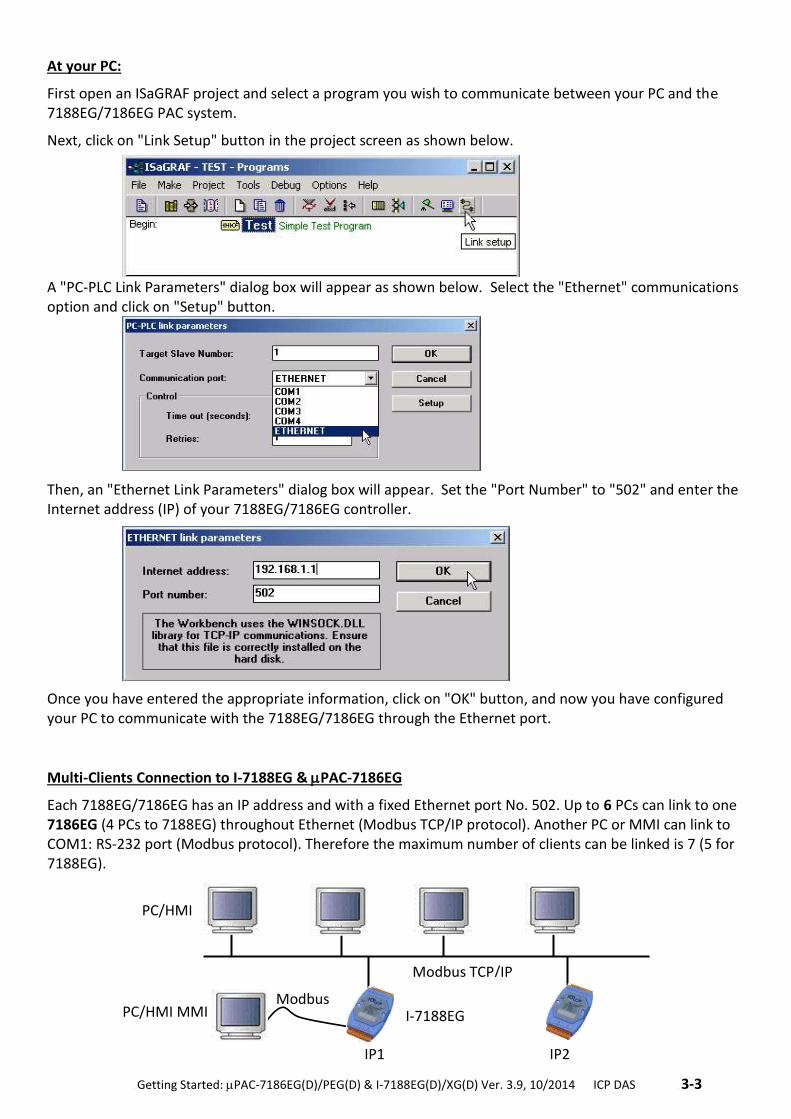
At your PC:
First open an ISaGRAF project and select a program you wish to communicate between your PC and the 7188EG/7186EG PAC system.
Next, click on "Link Setup" button in the project screen as shown below.
A "PC-PLC Link Parameters" dialog box will appear as shown below. Select the "Ethernet" communications option and click on "Setup" button.
Then, an "Ethernet Link Parameters" dialog box will appear. Set the "Port Number" to "502" and enter the Internet address (IP) of your 7188EG/7186EG controller.
Once you have entered the appropriate information, click on "OK" button, and now you have configured your PC to communicate with the 7188EG/7186EG through the Ethernet port.
Multi-Clients Connection to I-7188EG & PAC-7186EG
Each 7188EG/7186EG has an IP address and with a fixed Ethernet port No. 502. Up to 6 PCs can link to one 7186EG (4 PCs to 7188EG) throughout Ethernet (Modbus TCP/IP protocol). Another PC or MMI can link to COM1: RS-232 port (Modbus protocol). Therefore the maximum number of clients can be linked is 7 (5 for 7188EG).
PC/HMI MMI
Modbus TCP/IP
Modbus
IP1 IP2
I-7188EG
PC/HMI
3-4 . Getting Started: PAC-7186EG(D)/PEG(D) & I-7188EG(D)/XG(D) Ver. 3.9, 10/2014 ICP DAS ..
3.3 How to Update Hardware Driver
Our newly released driver can be obtained from the below website. http://www.icpdas.com/products/PAC/i-8000/isagraf.htm Steps: *** We use version 2.14 of 7188EG’s driver as an example to show how to know the current
driver version and how to upgrade the new driver. 1. Create a file folder named "7188" (or "7186")in your hard drive. For example: "c:\7188". 2. Copy the following listed files under
\Napdos\ISaGRAF\7188eg\Driver\2.14\ from CD or download the I-7188EG version 2.14 zip file from website of http://www.icpdas.com/products/PAC/i-8000/isagraf-link.htm into your "7188" folder. (If you download zip file from web please extract the file.)
1. 7188xw.exe 2. 7188xw.f4 3. 7188xw.ini 4. autoexec.bat 5. e-060915.img (e-060915.img for 7188EG Ver.2.14
xb060614.img for 7188XG Ver.2.12 86-080429.img for 7186EG Ver.1.02)
6. isa7188e.exe (isa7188e.exe for 7188EG isa7188.exe for 7188XG isa7186e.exe for 7186EG)
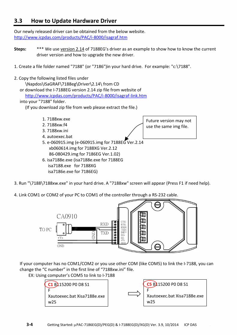
3. Run "\7188\7188xw.exe" in your hard drive. A "7188xw" screen will appear (Press F1 if need help). 4. Link COM1 or COM2 of your PC to COM1 of the controller through a RS-232 cable.
If your computer has no COM1/COM2 or you use other COM (like COM5) to link the I-7188, you can change the “C number” in the first line of “7188xw.ini” file. EX: Using computer’s COM5 to link to I-7188
C1 B115200 P0 D8 S1 F Xautoexec.bat Xisa7188e.exe w25
C5 B115200 P0 D8 S1 F Xautoexec.bat Xisa7188e.exe w25
Future version may not use the same img file.
.Getting Started: PAC-7186EG(D)/PEG(D) & I-7188EG(D)/XG(D) Ver. 3.9, 10/2014 ICP DAS .3-5
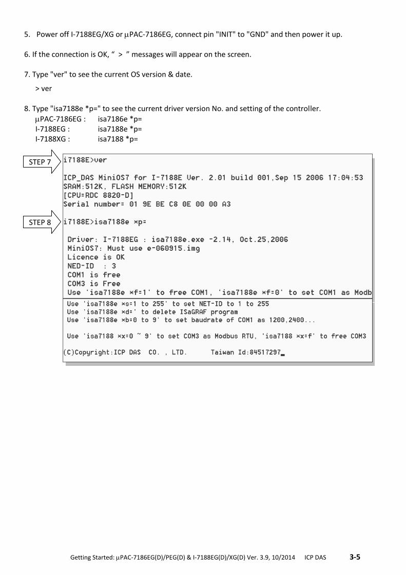
5. Power off I-7188EG/XG or PAC-7186EG, connect pin "INIT" to "GND" and then power it up. 6. If the connection is OK, “ > ” messages will appear on the screen. 7. Type "ver" to see the current OS version & date.
> ver 8. Type "isa7188e *p=" to see the current driver version No. and setting of the controller.
PAC-7186EG : isa7186e *p= I-7188EG : isa7188e *p= I-7188XG : isa7188 *p=
STEP 7
STEP 8
3-6 . Getting Started: PAC-7186EG(D)/PEG(D) & I-7188EG(D)/XG(D) Ver. 3.9, 10/2014 ICP DAS ..
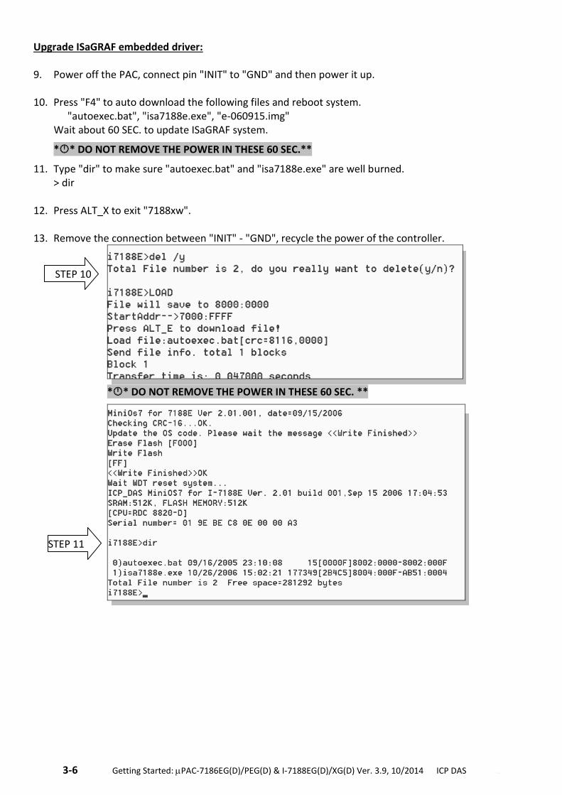
Upgrade ISaGRAF embedded driver: 9. Power off the PAC, connect pin "INIT" to "GND" and then power it up. 10. Press "F4" to auto download the following files and reboot system.
"autoexec.bat", "isa7188e.exe", "e-060915.img" Wait about 60 SEC. to update ISaGRAF system.
** DO NOT REMOVE THE POWER IN THESE 60 SEC.**
11. Type "dir" to make sure "autoexec.bat" and "isa7188e.exe" are well burned. > dir 12. Press ALT_X to exit "7188xw". 13. Remove the connection between "INIT" - "GND", recycle the power of the controller.
** DO NOT REMOVE THE POWER IN THESE 60 SEC. **
STEP 10
STEP 11
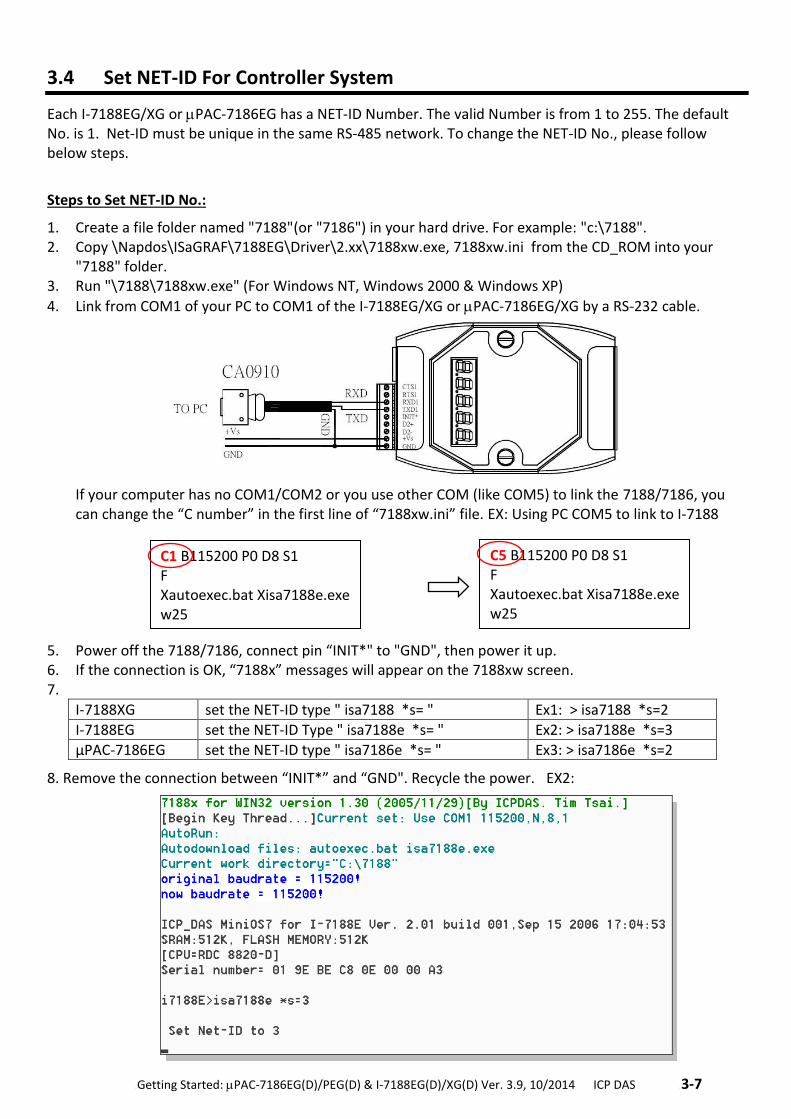
.Getting Started: PAC-7186EG(D)/PEG(D) & I-7188EG(D)/XG(D) Ver. 3.9, 10/2014 ICP DAS .3-7
3.4 Set NET-ID For Controller System
Each I-7188EG/XG or PAC-7186EG has a NET-ID Number. The valid Number is from 1 to 255. The default No. is 1. Net-ID must be unique in the same RS-485 network. To change the NET-ID No., please follow below steps.
Steps to Set NET-ID No.:
1. Create a file folder named "7188"(or "7186") in your hard drive. For example: "c:\7188". 2. Copy \Napdos\ISaGRAF\7188EG\Driver\2.xx\7188xw.exe, 7188xw.ini from the CD_ROM into your
"7188" folder. 3. Run "\7188\7188xw.exe" (For Windows NT, Windows 2000 & Windows XP)
4. Link from COM1 of your PC to COM1 of the I-7188EG/XG or PAC-7186EG/XG by a RS-232 cable.
If your computer has no COM1/COM2 or you use other COM (like COM5) to link the 7188/7186, you can change the “C number” in the first line of “7188xw.ini” file. EX: Using PC COM5 to link to I-7188
5. Power off the 7188/7186, connect pin “INIT*" to "GND", then power it up. 6. If the connection is OK, “7188x” messages will appear on the 7188xw screen. 7.
I-7188XG set the NET-ID type " isa7188 *s= " Ex1: > isa7188 *s=2
I-7188EG set the NET-ID Type " isa7188e *s= " Ex2: > isa7188e *s=3
μPAC-7186EG set the NET-ID type " isa7186e *s= " Ex3: > isa7186e *s=2
8. Remove the connection between “INIT*” and “GND". Recycle the power. EX2:
C1 B115200 P0 D8 S1 F Xautoexec.bat Xisa7188e.exe w25
C5 B115200 P0 D8 S1 F Xautoexec.bat Xisa7188e.exe w25
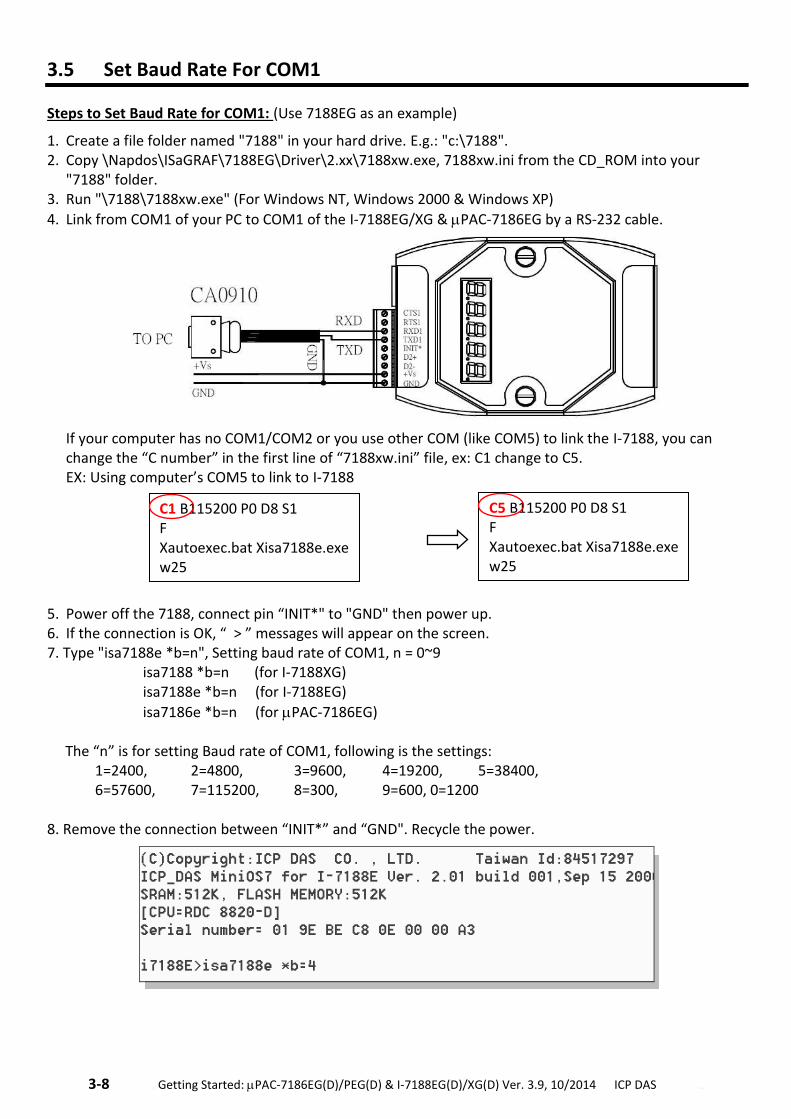
3-8 . Getting Started: PAC-7186EG(D)/PEG(D) & I-7188EG(D)/XG(D) Ver. 3.9, 10/2014 ICP DAS ..
3.5 Set Baud Rate For COM1
Steps to Set Baud Rate for COM1: (Use 7188EG as an example)
1. Create a file folder named "7188" in your hard drive. E.g.: "c:\7188". 2. Copy \Napdos\ISaGRAF\7188EG\Driver\2.xx\7188xw.exe, 7188xw.ini from the CD_ROM into your
"7188" folder. 3. Run "\7188\7188xw.exe" (For Windows NT, Windows 2000 & Windows XP)
4. Link from COM1 of your PC to COM1 of the I-7188EG/XG & PAC-7186EG by a RS-232 cable.
If your computer has no COM1/COM2 or you use other COM (like COM5) to link the I-7188, you can change the “C number” in the first line of “7188xw.ini” file, ex: C1 change to C5.
EX: Using computer’s COM5 to link to I-7188 5. Power off the 7188, connect pin “INIT*" to "GND" then power up. 6. If the connection is OK, “ > ” messages will appear on the screen. 7. Type "isa7188e *b=n", Setting baud rate of COM1, n = 0~9 isa7188 *b=n (for I-7188XG) isa7188e *b=n (for I-7188EG)
isa7186e *b=n (for PAC-7186EG) The “n” is for setting Baud rate of COM1, following is the settings: 1=2400, 2=4800, 3=9600, 4=19200, 5=38400, 6=57600, 7=115200, 8=300, 9=600, 0=1200 8. Remove the connection between “INIT*” and “GND". Recycle the power.
C1 B115200 P0 D8 S1 F Xautoexec.bat Xisa7188e.exe w25
C5 B115200 P0 D8 S1 F Xautoexec.bat Xisa7188e.exe w25
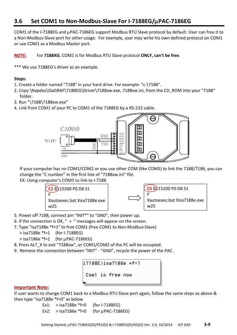
.Getting Started: PAC-7186EG(D)/PEG(D) & I-7188EG(D)/XG(D) Ver. 3.9, 10/2014 ICP DAS .3-9
3.6 Set COM1 to Non-Modbus-Slave For I-7188EG/PAC-7186EG
COM1 of the I-7188EG and PAC-7186EG support Modbus RTU Slave protocol by default. User can free it to a Non-Modbus-Slave port for other usage. For example, user may write his own defined protocol on COM1 or use COM1 as a Modbus Master port. NOTE: For 7188XG, COM1 is for Modbus RTU Slave protocol ONLY, can’t be free. *** We use 7188EG’s driver as an example. Steps: 1. Create a folder named "7188" in your hard drive. For example: "c:\7188". 2. Copy \Napdos\ISaGRAF\7188EG\Driver\7188xw.exe, 7188xw.ini, from the CD_ROM into your "7188"
folder. 3. Run "\7188\7188xw.exe" 4. Link from COM1 of your PC to COM1 of the 7188EG by a RS-232 cable.
If your computer has no COM1/COM2 or you use other COM (like COM5) to link the 7188/7186, you can change the “C number” in the first line of “7188xw.ini” file.
EX: Using computer’s COM5 to link to I-7188
5. Power off 7188, connect pin “INIT*" to "GND", then power up. 6. If the connection is OK, “ > ” messages will appear on the screen. 7. Type "isa7188e *f=1" to free COM1 (free COM1 to Non-Modbus-Slave) > isa7188e *f=1 (for I-7188EG)
> isa7186e *f=1 (for PAC-7186EG) 8. Press ALT_X to exit "7188xw", or COM1/COM2 of the PC will be occupied. 9. Remove the connection between "INIT" - "GND", recycle the power of the PAC.
Important Note: If user wants to change COM1 back to a Modbus RTU Slave port again, follow the same steps as above & then type "isa7188e *f=0" as below
Ex1: > isa7188e *f=0 (for I-7188EG)
Ex2: > isa7186e *f=0 (for PAC-7186EG)
C1 B115200 P0 D8 S1 F Xautoexec.bat Xisa7188e.exe w25
C5 B115200 P0 D8 S1 F Xautoexec.bat Xisa7188e.exe w25
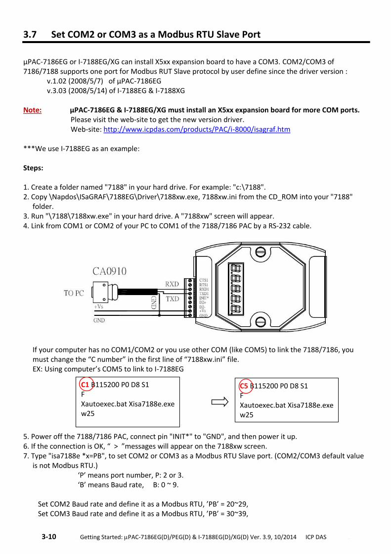
3-10 . Getting Started: PAC-7186EG(D)/PEG(D) & I-7188EG(D)/XG(D) Ver. 3.9, 10/2014 ICP DAS ..
3.7 Set COM2 or COM3 as a Modbus RTU Slave Port
µPAC-7186EG or I-7188EG/XG can install X5xx expansion board to have a COM3. COM2/COM3 of 7186/7188 supports one port for Modbus RUT Slave protocol by user define since the driver version : v.1.02 (2008/5/7) of µPAC-7186EG v.3.03 (2008/5/14) of I-7188EG & I-7188XG Note: µPAC-7186EG & I-7188EG/XG must install an X5xx expansion board for more COM ports.
Please visit the web-site to get the new version driver. Web-site: http://www.icpdas.com/products/PAC/i-8000/isagraf.htm
***We use I-7188EG as an example: Steps: 1. Create a folder named "7188" in your hard drive. For example: "c:\7188". 2. Copy \Napdos\ISaGRAF\7188EG\Driver\7188xw.exe, 7188xw.ini from the CD_ROM into your "7188"
folder. 3. Run "\7188\7188xw.exe" in your hard drive. A "7188xw" screen will appear. 4. Link from COM1 or COM2 of your PC to COM1 of the 7188/7186 PAC by a RS-232 cable.
If your computer has no COM1/COM2 or you use other COM (like COM5) to link the 7188/7186, you must change the “C number” in the first line of “7188xw.ini” file. EX: Using computer’s COM5 to link to I-7188EG
5. Power off the 7188/7186 PAC, connect pin "INIT*" to "GND", and then power it up. 6. If the connection is OK, “ > ”messages will appear on the 7188xw screen. 7. Type "isa7188e *x=PB", to set COM2 or COM3 as a Modbus RTU Slave port. (COM2/COM3 default value
is not Modbus RTU.) ‘P’ means port number, P: 2 or 3. ‘B’ means Baud rate, B: 0 ~ 9. Set COM2 Baud rate and define it as a Modbus RTU, ’PB’ = 20~29, Set COM3 Baud rate and define it as a Modbus RTU, ’PB’ = 30~39,
C5 B115200 P0 D8 S1 F Xautoexec.bat Xisa7188e.exe w25
C1 B115200 P0 D8 S1 F Xautoexec.bat Xisa7188e.exe w25
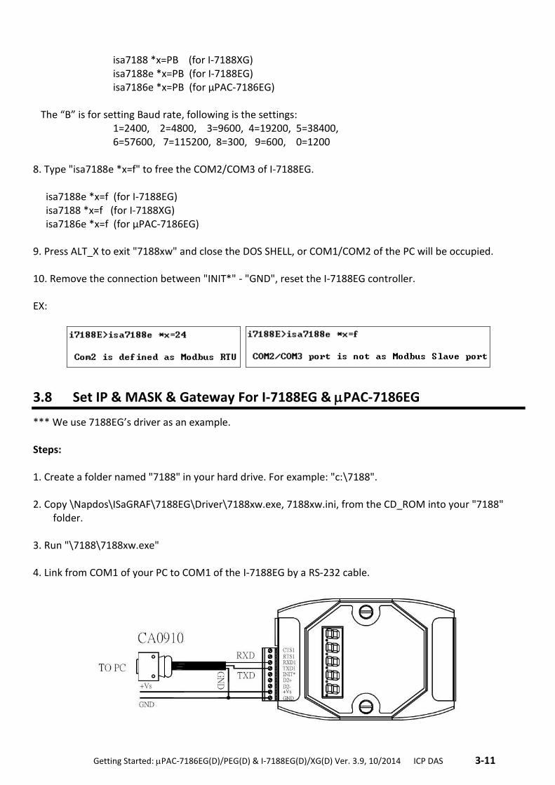
.Getting Started: PAC-7186EG(D)/PEG(D) & I-7188EG(D)/XG(D) Ver. 3.9, 10/2014 ICP DAS .3-11
isa7188 *x=PB (for I-7188XG) isa7188e *x=PB (for I-7188EG) isa7186e *x=PB (for µPAC-7186EG)
The “B” is for setting Baud rate, following is the settings:
1=2400, 2=4800, 3=9600, 4=19200, 5=38400, 6=57600, 7=115200, 8=300, 9=600, 0=1200
8. Type "isa7188e *x=f" to free the COM2/COM3 of I-7188EG. isa7188e *x=f (for I-7188EG) isa7188 *x=f (for I-7188XG) isa7186e *x=f (for µPAC-7186EG) 9. Press ALT_X to exit "7188xw" and close the DOS SHELL, or COM1/COM2 of the PC will be occupied. 10. Remove the connection between "INIT*" - "GND", reset the I-7188EG controller. EX:
3.8 Set IP & MASK & Gateway For I-7188EG & PAC-7186EG
*** We use 7188EG’s driver as an example. Steps: 1. Create a folder named "7188" in your hard drive. For example: "c:\7188". 2. Copy \Napdos\ISaGRAF\7188EG\Driver\7188xw.exe, 7188xw.ini, from the CD_ROM into your "7188"
folder. 3. Run "\7188\7188xw.exe" 4. Link from COM1 of your PC to COM1 of the I-7188EG by a RS-232 cable.
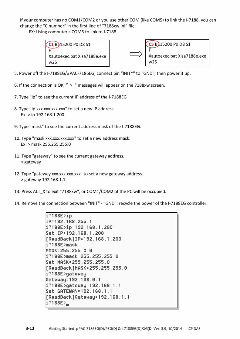
3-12 . Getting Started: PAC-7186EG(D)/PEG(D) & I-7188EG(D)/XG(D) Ver. 3.9, 10/2014 ICP DAS ..
If your computer has no COM1/COM2 or you use other COM (like COM5) to link the I-7188, you can change the “C number” in the first line of “7188xw.ini” file. EX: Using computer’s COM5 to link to I-7188
5. Power off the I-7188EG/PAC-7186EG, connect pin “INIT*" to "GND", then power it up. 6. If the connection is OK, “ > ” messages will appear on the 7188xw screen. 7. Type "ip" to see the current IP address of the I-7188EG 8. Type "ip xxx.xxx.xxx.xxx" to set a new IP address. Ex: > ip 192.168.1.200 9. Type "mask" to see the current address mask of the I-7188EG. 10. Type "mask xxx.xxx.xxx.xxx" to set a new address mask. Ex: > mask 255.255.255.0 11. Type "gateway" to see the current gateway address. > gateway 12. Type "gateway xxx.xxx.xxx.xxx" to set a new gateway address. > gateway 192.168.1.1 13. Press ALT_X to exit "7188xw", or COM1/COM2 of the PC will be occupied. 14. Remove the connection between "INIT" - "GND", recycle the power of the I-7188EG controller.
C1 B115200 P0 D8 S1 F Xautoexec.bat Xisa7188e.exe w25
C5 B115200 P0 D8 S1 F Xautoexec.bat Xisa7188e.exe w25
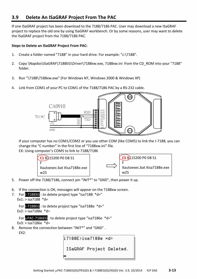
.Getting Started: PAC-7186EG(D)/PEG(D) & I-7188EG(D)/XG(D) Ver. 3.9, 10/2014 ICP DAS .3-13
3.9 Delete An ISaGRAF Project From The PAC
If one ISaGRAF project has been download to the 7188/7186 PAC. User may download a new ISaGRAF project to replace the old one by using ISaGRAF workbench. Or by some reasons, user may want to delete the ISaGRAF project from the 7188/7186 PAC. Steps to Delete an ISaGRAF Project From PAC:
1. Create a folder named "7188" in your hard drive. For example: "c:\7188".
2. Copy \Napdos\ISaGRAF\7188EG\Driver\7188xw.exe, 7188xw.ini from the CD_ROM into your "7188" folder.
3. Run "\7188\7188xw.exe" (For Windows NT, Windows 2000 & Windows XP) 4. Link from COM1 of your PC to COM1 of the 7188/7186 PAC by a RS-232 cable.
If your computer has no COM1/COM2 or you use other COM (like COM5) to link the I-7188, you can change the “C number” in the first line of “7188xw.ini” file.
EX: Using computer’s COM5 to link to 7188/7186 5. Power off the 7188/7186, connect pin “INIT*" to "GND", then power it up. 6. If the connection is OK, messages will appear on the 7188xw screen. 7. For I-7188XG : to delete project type "isa7188 *d=" Ex1: > isa7188 *d=
For I-7188EG : to delete project type "isa7188e *d=" Ex2: > isa7188e *d=
For PAC-7186EG : to delete project type "isa7186e *d=" Ex3: > isa7186e *d= 8. Remove the connection between “INIT*” and “GND" .
EX2:
C1 B115200 P0 D8 S1 F Xautoexec.bat Xisa7188e.exe w25
C5 B115200 P0 D8 S1 F Xautoexec.bat Xisa7188e.exe w25
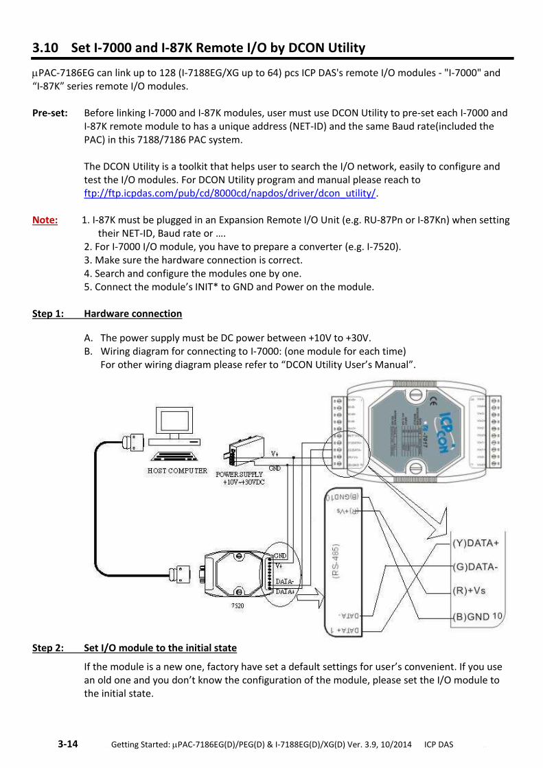
3-14 . Getting Started: PAC-7186EG(D)/PEG(D) & I-7188EG(D)/XG(D) Ver. 3.9, 10/2014 ICP DAS ..
3.10 Set I-7000 and I-87K Remote I/O by DCON Utility
PAC-7186EG can link up to 128 (I-7188EG/XG up to 64) pcs ICP DAS's remote I/O modules - "I-7000" and “I-87K” series remote I/O modules. Pre-set: Before linking I-7000 and I-87K modules, user must use DCON Utility to pre-set each I-7000 and
I-87K remote module to has a unique address (NET-ID) and the same Baud rate(included the PAC) in this 7188/7186 PAC system. The DCON Utility is a toolkit that helps user to search the I/O network, easily to configure and test the I/O modules. For DCON Utility program and manual please reach to ftp://ftp.icpdas.com/pub/cd/8000cd/napdos/driver/dcon_utility/.
Note: 1. I-87K must be plugged in an Expansion Remote I/O Unit (e.g. RU-87Pn or I-87Kn) when setting their NET-ID, Baud rate or ….
2. For I-7000 I/O module, you have to prepare a converter (e.g. I-7520). 3. Make sure the hardware connection is correct. 4. Search and configure the modules one by one. 5. Connect the module’s INIT* to GND and Power on the module.
Step 1: Hardware connection
A. The power supply must be DC power between +10V to +30V. B. Wiring diagram for connecting to I-7000: (one module for each time)
For other wiring diagram please refer to “DCON Utility User’s Manual”.
Step 2: Set I/O module to the initial state
If the module is a new one, factory have set a default settings for user’s convenient. If you use an old one and you don’t know the configuration of the module, please set the I/O module to the initial state.
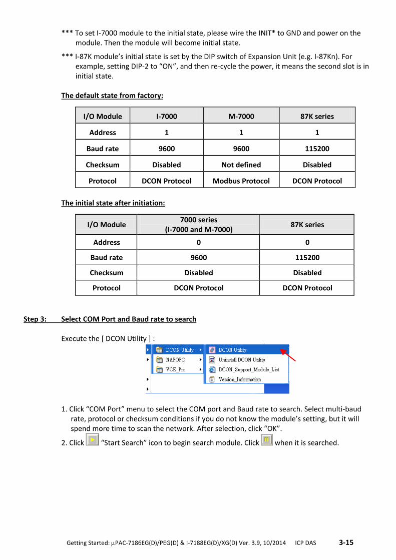
.Getting Started: PAC-7186EG(D)/PEG(D) & I-7188EG(D)/XG(D) Ver. 3.9, 10/2014 ICP DAS .3-15
*** To set I-7000 module to the initial state, please wire the INIT* to GND and power on the module. Then the module will become initial state.
*** I-87K module’s initial state is set by the DIP switch of Expansion Unit (e.g. I-87Kn). For example, setting DIP-2 to “ON”, and then re-cycle the power, it means the second slot is in initial state.
The default state from factory:
I/O Module I-7000 M-7000 87K series
Address 1 1 1
Baud rate 9600 9600 115200
Checksum Disabled Not defined Disabled
Protocol DCON Protocol Modbus Protocol DCON Protocol
The initial state after initiation:
I/O Module 7000 series
(I-7000 and M-7000) 87K series
Address 0 0
Baud rate 9600 115200
Checksum Disabled Disabled
Protocol DCON Protocol DCON Protocol
Step 3: Select COM Port and Baud rate to search Execute the [ DCON Utility ] :
1. Click “COM Port” menu to select the COM port and Baud rate to search. Select multi-baud
rate, protocol or checksum conditions if you do not know the module’s setting, but it will spend more time to scan the network. After selection, click “OK”.
2. Click “Start Search” icon to begin search module. Click when it is searched.
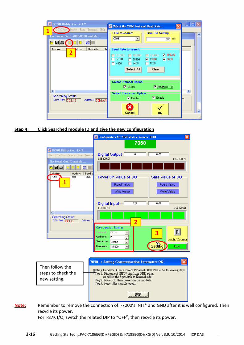
3-16 . Getting Started: PAC-7186EG(D)/PEG(D) & I-7188EG(D)/XG(D) Ver. 3.9, 10/2014 ICP DAS ..
Step 4: Click Searched module ID and give the new configuration
Note: Remember to remove the connection of I-7000’s INIT* and GND after it is well configured. Then
recycle its power. For I-87K I/O, switch the related DIP to “OFF”, then recycle its power.
1
2
1
2
3
Then follow the steps to check the new setting.
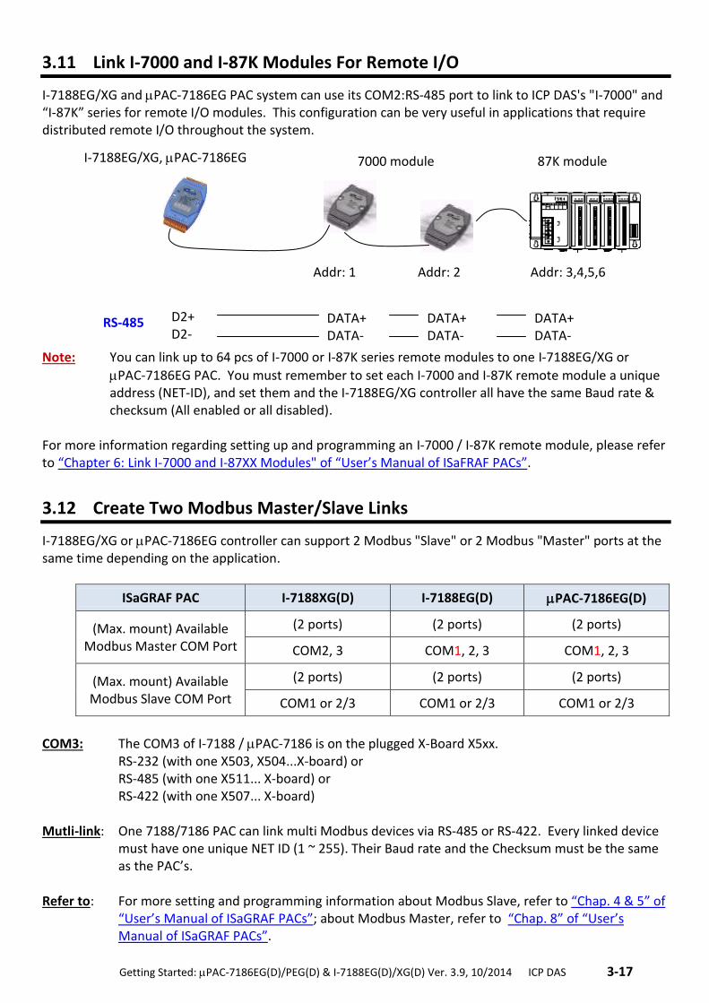
.Getting Started: PAC-7186EG(D)/PEG(D) & I-7188EG(D)/XG(D) Ver. 3.9, 10/2014 ICP DAS .3-17
3.11 Link I-7000 and I-87K Modules For Remote I/O
I-7188EG/XG and PAC-7186EG PAC system can use its COM2:RS-485 port to link to ICP DAS's "I-7000" and “I-87K” series for remote I/O modules. This configuration can be very useful in applications that require distributed remote I/O throughout the system.
Note: You can link up to 64 pcs of I-7000 or I-87K series remote modules to one I-7188EG/XG or
PAC-7186EG PAC. You must remember to set each I-7000 and I-87K remote module a unique address (NET-ID), and set them and the I-7188EG/XG controller all have the same Baud rate & checksum (All enabled or all disabled).
For more information regarding setting up and programming an I-7000 / I-87K remote module, please refer to “Chapter 6: Link I-7000 and I-87XX Modules" of “User’s Manual of ISaFRAF PACs”.
3.12 Create Two Modbus Master/Slave Links
I-7188EG/XG or PAC-7186EG controller can support 2 Modbus "Slave" or 2 Modbus "Master" ports at the same time depending on the application.
ISaGRAF PAC I-7188XG(D) I-7188EG(D) PAC-7186EG(D)
(Max. mount) Available Modbus Master COM Port
(2 ports) (2 ports) (2 ports)
COM2, 3 COM1, 2, 3 COM1, 2, 3
(Max. mount) Available Modbus Slave COM Port
(2 ports) (2 ports) (2 ports)
COM1 or 2/3 COM1 or 2/3 COM1 or 2/3
COM3: The COM3 of I-7188 / PAC-7186 is on the plugged X-Board X5xx. RS-232 (with one X503, X504...X-board) or RS-485 (with one X511... X-board) or RS-422 (with one X507... X-board)
Mutli-link: One 7188/7186 PAC can link multi Modbus devices via RS-485 or RS-422. Every linked device
must have one unique NET ID (1 ~ 255). Their Baud rate and the Checksum must be the same as the PAC’s.
Refer to: For more setting and programming information about Modbus Slave, refer to “Chap. 4 & 5” of
“User’s Manual of ISaGRAF PACs”; about Modbus Master, refer to “Chap. 8” of “User’s Manual of ISaGRAF PACs”.
7000 module
Addr: 1 Addr: 2 Addr: 3,4,5,6
87K module I-7188EG/XG, PAC-7186EG
D2+ D2-
DATA+ DATA-
DATA+ DATA-
DATA+ DATA-
RS-485
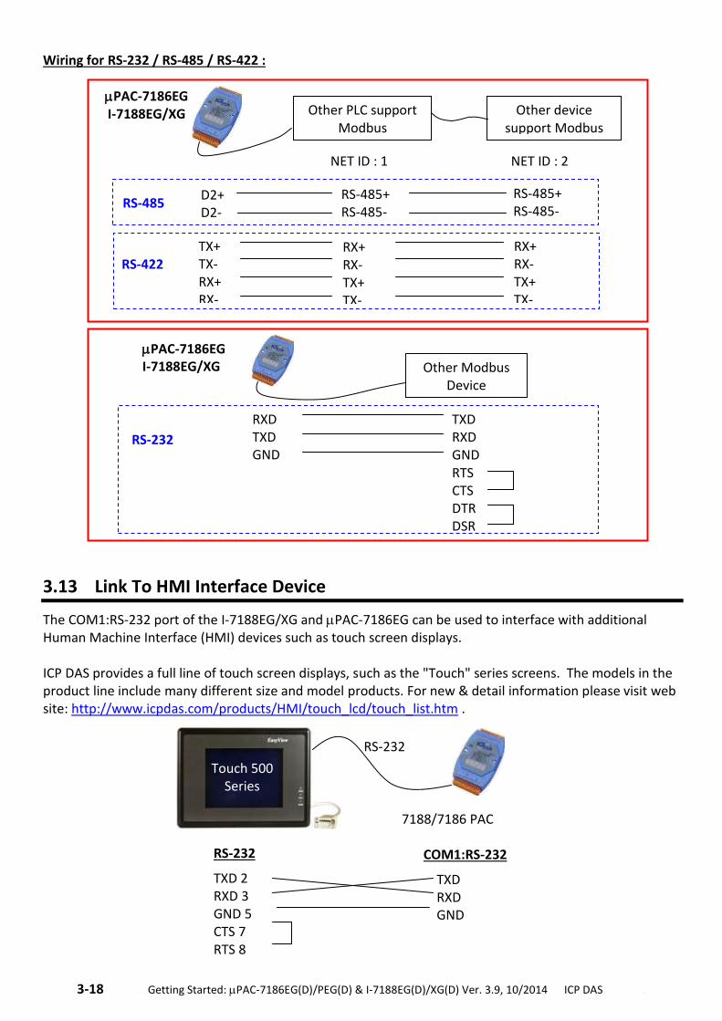
3-18 . Getting Started: PAC-7186EG(D)/PEG(D) & I-7188EG(D)/XG(D) Ver. 3.9, 10/2014 ICP DAS ..
Wiring for RS-232 / RS-485 / RS-422 :
3.13 Link To HMI Interface Device
The COM1:RS-232 port of the I-7188EG/XG and PAC-7186EG can be used to interface with additional Human Machine Interface (HMI) devices such as touch screen displays. ICP DAS provides a full line of touch screen displays, such as the "Touch" series screens. The models in the product line include many different size and model products. For new & detail information please visit web site: http://www.icpdas.com/products/HMI/touch_lcd/touch_list.htm .
D2+ D2-
RS-485 RS-485+ RS-485-
RS-485+ RS-485-
Other PLC support Modbus
Other device support Modbus
NET ID : 1 NET ID : 2
PAC-7186EG I-7188EG/XG
TX+ TX- RX+ RX-
RS-422 RX+ RX- TX+ TX-
RX+ RX- TX+ TX-
Other Modbus Device
PAC-7186EG I-7188EG/XG
TXD RXD GND RTS CTS DTR DSR
RXD TXD GND
RS-232
RS-232
TXD 2 RXD 3 GND 5 CTS 7 RTS 8
COM1:RS-232
TXD RXD GND
Touch 500 Series
RS-232
7188/7186 PAC
.Getting Started: PAC-7186EG(D)/PEG(D) & I-7188EG(D)/XG(D) Ver. 3.9, 10/2014 ICP DAS .3-19
3.14 Use I/O Expansion Boards : X-Board Series
I-7188EG/XG & PAC-7186EG can plug an I/O Expansion board inside the main box. To install it, user has to
loosen the screw, remove the shell of I-7188EG/XG or PAC-7186EG and then plug in the X-board.
Note: I-7188EG/XG and PAC-7186EG does not support the EEPROM and Flash memory of X-board. Following lists are the common used X-Boards. Most of them have RoHS compliant model (model number with CR) to protect our environment. Please visit our website for newest model information. http://www.icpdas.com/products/PAC/i-o_expansion/x_list.htm
X107 : 6 D/I & 7 D/O X109 : 7 PhotoMos Relay X110 : 14 D/I X111 : 13 D/O X116 : 4 D/I & 6 Relay X119 : 7 D/I & 7 D/O X202 : 7 A/D (0 ~ 20mA, 12 bit) X203 : 2 A/D (0 ~ 20mA, 12 bit), 2 D/I & 6 D/O X303 : 1 A/D (+/- 5V, 12 bit), 1 D/A (+/- 5V, 12 bit), 4 D/I & 6 D/O X304 : 3 A/D (+/- 5V, 12 bit), 1 D/A (+/- 5V, 12 bit), 4 D/I & 4 D/O X305 : 7 A/D (+/- 5V, 12 bit), 1 D/A (+/- 5V, 12 bit), 2 D/I & 2 D/O X308 : 4 A/D (0 ~ 10V, 12 bit), 6 D/O X310 : 1 A/D ( 0~10V, 12 bit), 1 A/D ( 0~20mA, 12 bit), 2 D/A ( 0~10V, 12 bit) & 3 D/I & 3 D/O X503 : 1 RS-232 : COM3(5 pin) X504 : 2 RS-232 : COM3(5 pin), COM4(9 pin) X505 : 3 RS-232 : COM3~COM5 (5 pin) X506 : 6 RS-232 : COM3~COM8 (3 pin) X507 : 1 RS-422/485 : COM3, 4 D/I & 4 D/O X508 : 1 RS-232 : COM3(5 pin), 4 D/I & 4 D/O X509 : 2 RS-232 : COM3~COM4(3 pin), 4 D/I & 4 D/O X510 : 1 RS-232 : COM3(3 pin), 5 D/I & 5 D/O X510-128 : 1 RS-232 : COM3(3 pin), 5 D/I & 5 D/O X511 : 3 RS-485 : COM3~COM5 X518 : 1 RS-232 : COM3(5 pin), 8 D/O X560/561 : 3 RS-232 : COM3~COM5(3 pin) X607 : 128KB NV-SRAM X608 : 512KB NV-SRAM X702 : 2-axis, 24-bit encoder X703 : 3-axis, 24-bit encoder *RS-232 : 3 pin: RXD, TXD, GND
5 pin: RTS, CTS, RXD, TXD, GND 9 pin: TXD, RXD, RTS, CTS, DSR, DTR, DCD, RI, GND
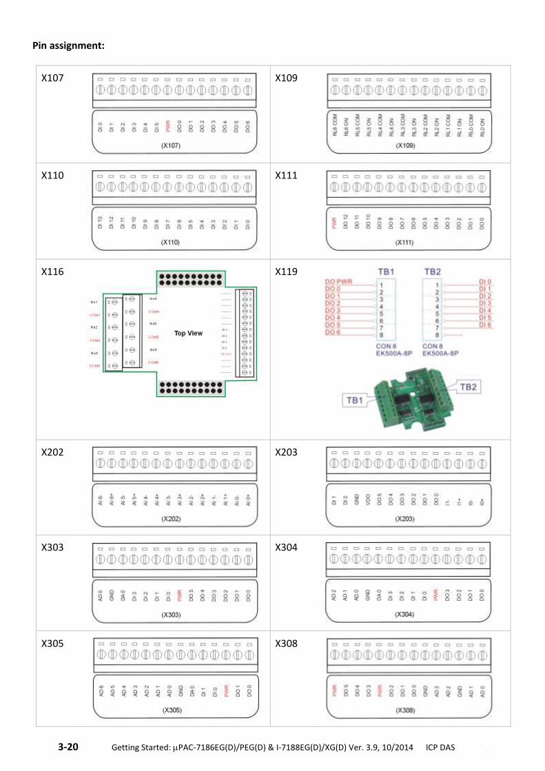
3-20 . Getting Started: PAC-7186EG(D)/PEG(D) & I-7188EG(D)/XG(D) Ver. 3.9, 10/2014 ICP DAS ..
Pin assignment:
X107
X109
X110
X111
X116
X119
X202
X203
X303
X304
X305
X308
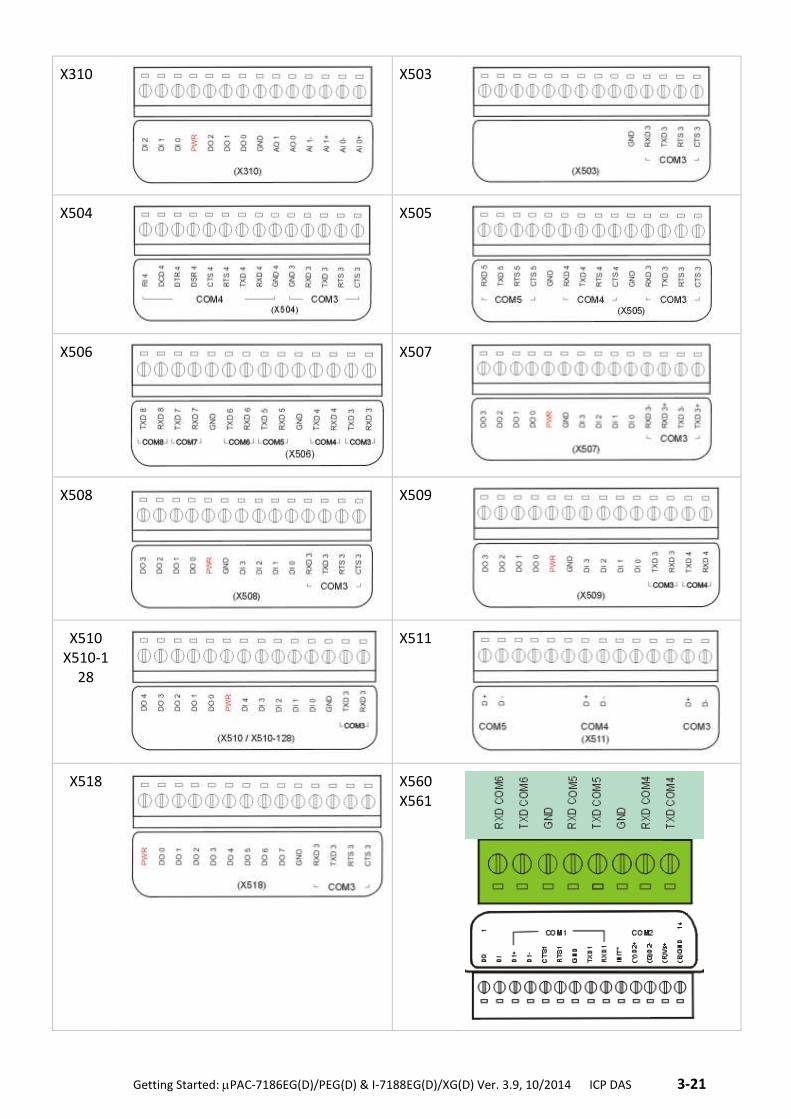
.Getting Started: PAC-7186EG(D)/PEG(D) & I-7188EG(D)/XG(D) Ver. 3.9, 10/2014 ICP DAS .3-21
X310
X503
X504
X505
X506
X507
X508
X509
X510 X510-1
28
X511
X518
X560 X561
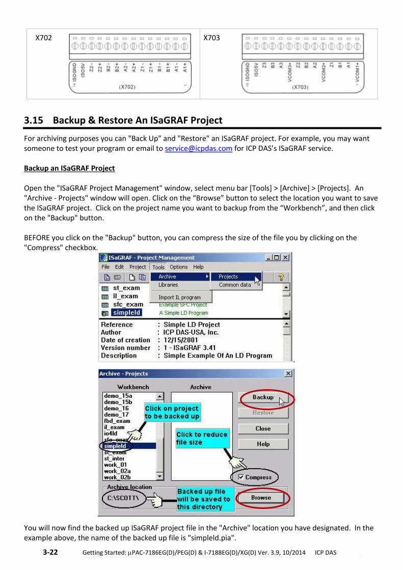
3-22 . Getting Started: PAC-7186EG(D)/PEG(D) & I-7188EG(D)/XG(D) Ver. 3.9, 10/2014 ICP DAS ..
X702
X703
3.15 Backup & Restore An ISaGRAF Project
For archiving purposes you can "Back Up" and "Restore" an ISaGRAF project. For example, you may want someone to test your program or email to [email protected] for ICP DAS’s ISaGRAF service. Backup an ISaGRAF Project Open the "ISaGRAF Project Management" window, select menu bar [Tools] > [Archive] > [Projects]. An "Archive - Projects" window will open. Click on the “Browse” button to select the location you want to save the ISaGRAF project. Click on the project name you want to backup from the “Workbench”, and then click on the "Backup" button. BEFORE you click on the "Backup" button, you can compress the size of the file you by clicking on the "Compress" checkbox.
You will now find the backed up ISaGRAF project file in the "Archive" location you have designated. In the example above, the name of the backed up file is "simpleld.pia".
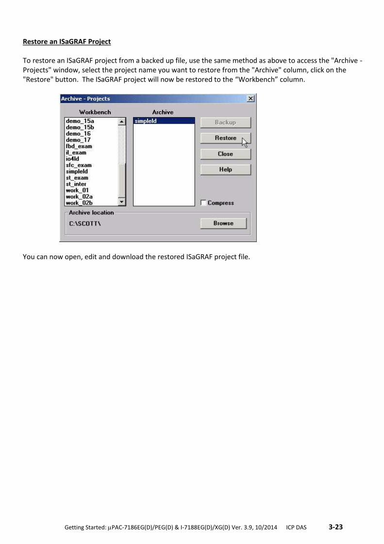
.Getting Started: PAC-7186EG(D)/PEG(D) & I-7188EG(D)/XG(D) Ver. 3.9, 10/2014 ICP DAS .3-23
Restore an ISaGRAF Project To restore an ISaGRAF project from a backed up file, use the same method as above to access the "Archive - Projects" window, select the project name you want to restore from the "Archive" column, click on the "Restore" button. The ISaGRAF project will now be restored to the “Workbench” column.
You can now open, edit and download the restored ISaGRAF project file.
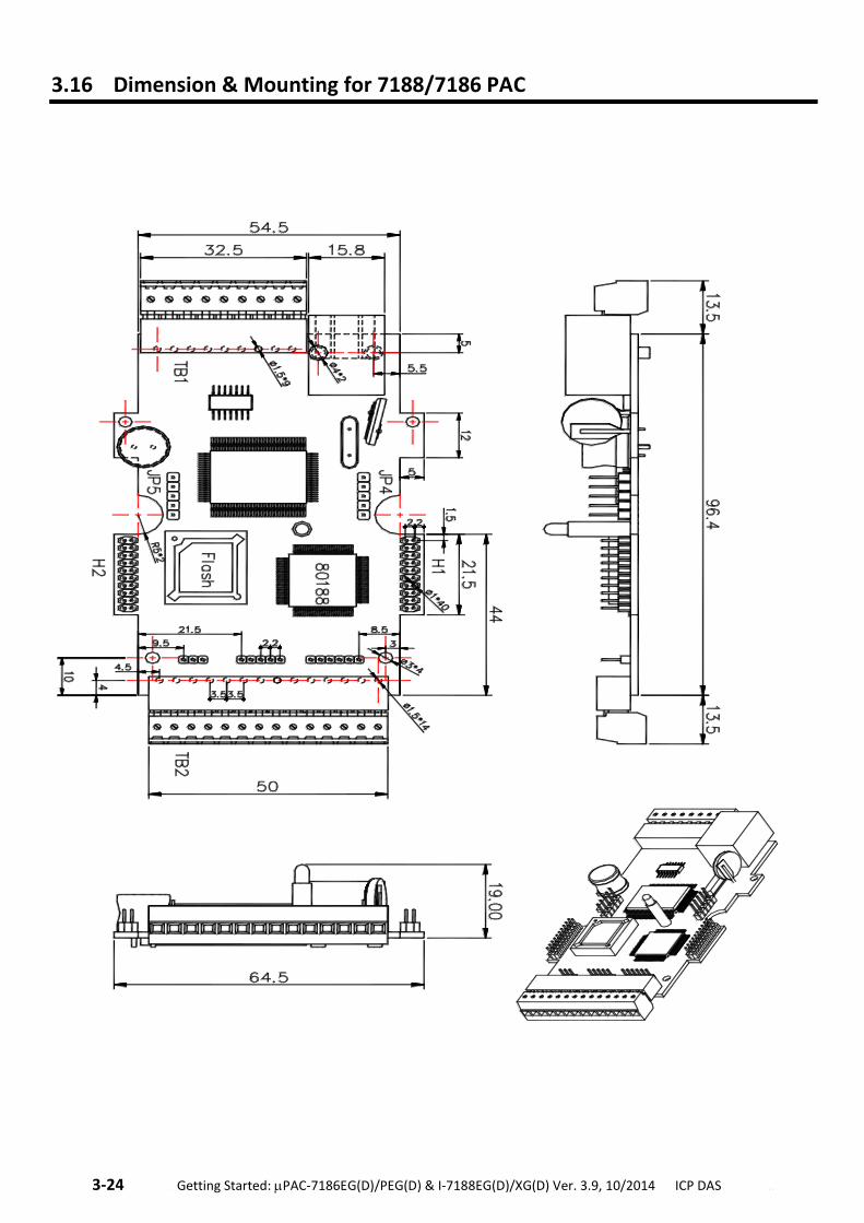
3-24 . Getting Started: PAC-7186EG(D)/PEG(D) & I-7188EG(D)/XG(D) Ver. 3.9, 10/2014 ICP DAS ..
3.16 Dimension & Mounting for 7188/7186 PAC
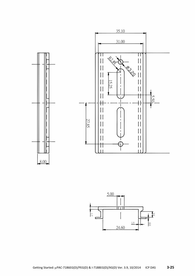
.Getting Started: PAC-7186EG(D)/PEG(D) & I-7188EG(D)/XG(D) Ver. 3.9, 10/2014 ICP DAS .3-25
68.00
5.50
15.25R2.54
0.91.5
3.9
1.7
5.00
24.60
31.00
35.10
27.85
8.00
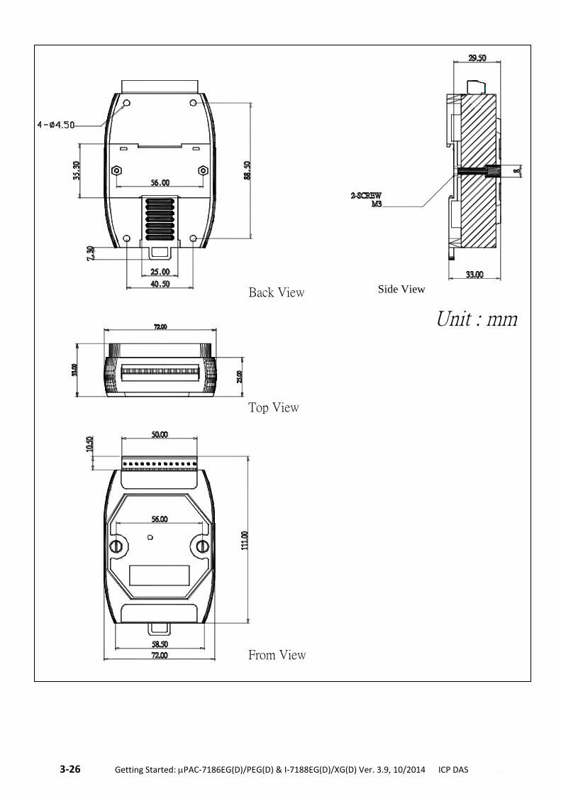
3-26 . Getting Started: PAC-7186EG(D)/PEG(D) & I-7188EG(D)/XG(D) Ver. 3.9, 10/2014 ICP DAS ..
Back View
Top View
From View
Side View
Side View
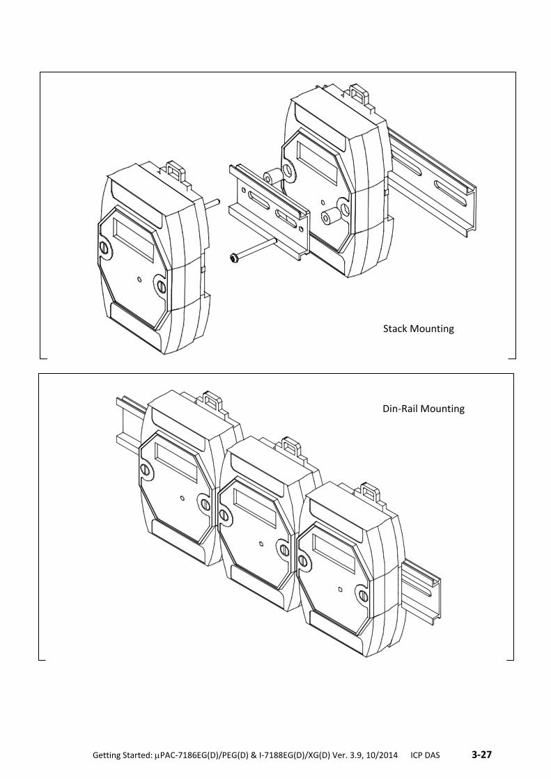
.Getting Started: PAC-7186EG(D)/PEG(D) & I-7188EG(D)/XG(D) Ver. 3.9, 10/2014 ICP DAS .3-27
Stack Mounting
Din-Rail Mounting
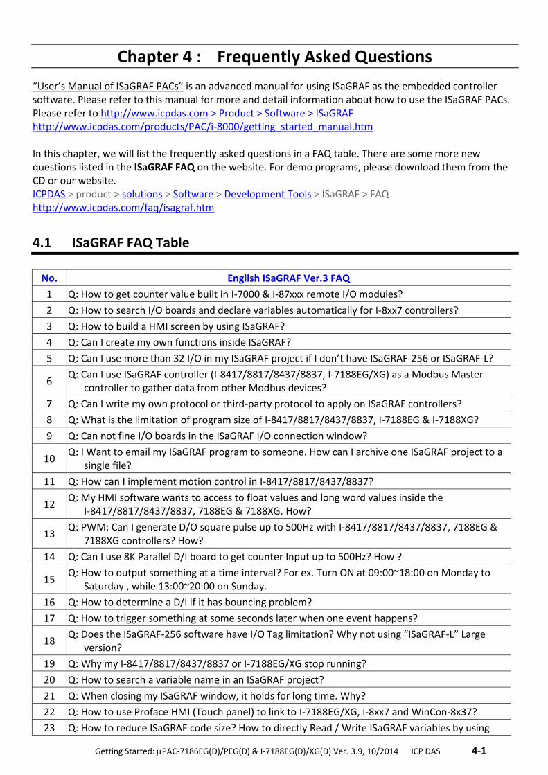
.Getting Started: PAC-7186EG(D)/PEG(D) & I-7188EG(D)/XG(D) Ver. 3.9, 10/2014 ICP DAS .4-1
Chapter 4 : Frequently Asked Questions
“User’s Manual of ISaGRAF PACs” is an advanced manual for using ISaGRAF as the embedded controller software. Please refer to this manual for more and detail information about how to use the ISaGRAF PACs. Please refer to http://www.icpdas.com > Product > Software > ISaGRAF http://www.icpdas.com/products/PAC/i-8000/getting_started_manual.htm In this chapter, we will list the frequently asked questions in a FAQ table. There are some more new questions listed in the ISaGRAF FAQ on the website. For demo programs, please download them from the CD or our website. ICPDAS > product > solutions > Software > Development Tools > ISaGRAF > FAQ http://www.icpdas.com/faq/isagraf.htm
4.1 ISaGRAF FAQ Table
No. English ISaGRAF Ver.3 FAQ
1 Q: How to get counter value built in I-7000 & I-87xxx remote I/O modules?
2 Q: How to search I/O boards and declare variables automatically for I-8xx7 controllers?
3 Q: How to build a HMI screen by using ISaGRAF?
4 Q: Can I create my own functions inside ISaGRAF?
5 Q: Can I use more than 32 I/O in my ISaGRAF project if I don’t have ISaGRAF-256 or ISaGRAF-L?
6 Q: Can I use ISaGRAF controller (I-8417/8817/8437/8837, I-7188EG/XG) as a Modbus Master
controller to gather data from other Modbus devices?
7 Q: Can I write my own protocol or third-party protocol to apply on ISaGRAF controllers?
8 Q: What is the limitation of program size of I-8417/8817/8437/8837, I-7188EG & I-7188XG?
9 Q: Can not fine I/O boards in the ISaGRAF I/O connection window?
10 Q: I Want to email my ISaGRAF program to someone. How can I archive one ISaGRAF project to a
single file?
11 Q: How can I implement motion control in I-8417/8817/8437/8837?
12 Q: My HMI software wants to access to float values and long word values inside the
I-8417/8817/8437/8837, 7188EG & 7188XG. How?
13 Q: PWM: Can I generate D/O square pulse up to 500Hz with I-8417/8817/8437/8837, 7188EG &
7188XG controllers? How?
14 Q: Can I use 8K Parallel D/I board to get counter Input up to 500Hz? How ?
15 Q: How to output something at a time interval? For ex. Turn ON at 09:00~18:00 on Monday to
Saturday , while 13:00~20:00 on Sunday.
16 Q: How to determine a D/I if it has bouncing problem?
17 Q: How to trigger something at some seconds later when one event happens?
18 Q: Does the ISaGRAF-256 software have I/O Tag limitation? Why not using “ISaGRAF-L” Large
version?
19 Q: Why my I-8417/8817/8437/8837 or I-7188EG/XG stop running?
20 Q: How to search a variable name in an ISaGRAF project?
21 Q: When closing my ISaGRAF window, it holds for long time. Why?
22 Q: How to use Proface HMI (Touch panel) to link to I-7188EG/XG, I-8xx7 and WinCon-8x37?
23 Q: How to reduce ISaGRAF code size? How to directly Read / Write ISaGRAF variables by using
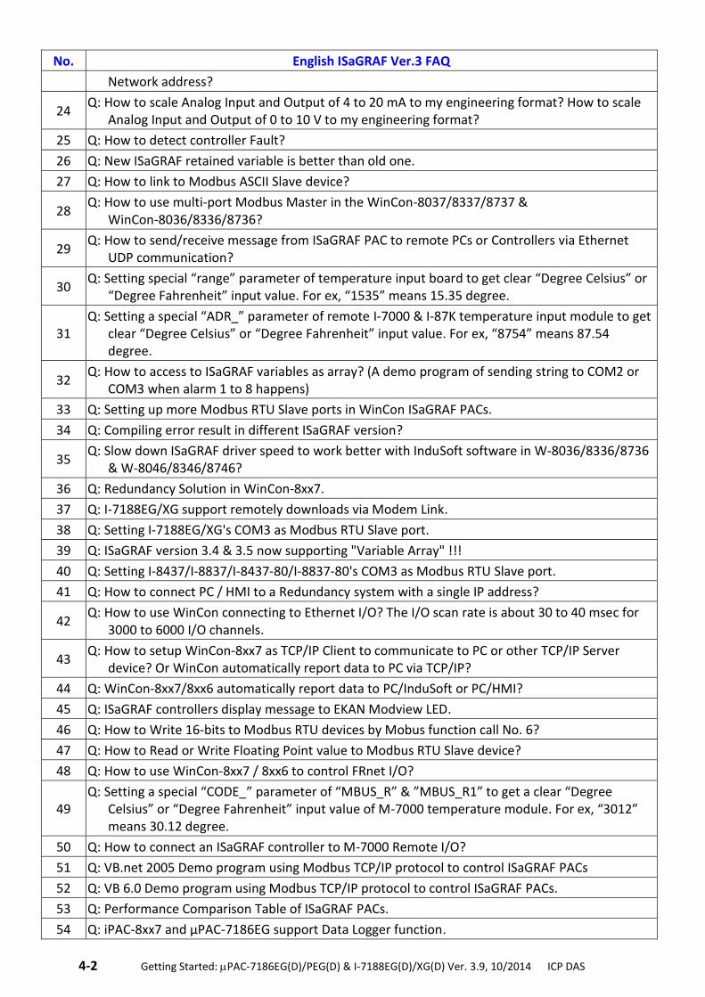
4-2 . Getting Started: PAC-7186EG(D)/PEG(D) & I-7188EG(D)/XG(D) Ver. 3.9, 10/2014 ICP DAS ..
No. English ISaGRAF Ver.3 FAQ
Network address?
24 Q: How to scale Analog Input and Output of 4 to 20 mA to my engineering format? How to scale
Analog Input and Output of 0 to 10 V to my engineering format?
25 Q: How to detect controller Fault?
26 Q: New ISaGRAF retained variable is better than old one.
27 Q: How to link to Modbus ASCII Slave device?
28 Q: How to use multi-port Modbus Master in the WinCon-8037/8337/8737 &
WinCon-8036/8336/8736?
29 Q: How to send/receive message from ISaGRAF PAC to remote PCs or Controllers via Ethernet
UDP communication?
30 Q: Setting special “range” parameter of temperature input board to get clear “Degree Celsius” or
“Degree Fahrenheit” input value. For ex, “1535” means 15.35 degree.
31 Q: Setting a special “ADR_” parameter of remote I-7000 & I-87K temperature input module to get
clear “Degree Celsius” or “Degree Fahrenheit” input value. For ex, “8754” means 87.54 degree.
32 Q: How to access to ISaGRAF variables as array? (A demo program of sending string to COM2 or
COM3 when alarm 1 to 8 happens)
33 Q: Setting up more Modbus RTU Slave ports in WinCon ISaGRAF PACs.
34 Q: Compiling error result in different ISaGRAF version?
35 Q: Slow down ISaGRAF driver speed to work better with InduSoft software in W-8036/8336/8736
& W-8046/8346/8746?
36 Q: Redundancy Solution in WinCon-8xx7.
37 Q: I-7188EG/XG support remotely downloads via Modem Link.
38 Q: Setting I-7188EG/XG's COM3 as Modbus RTU Slave port.
39 Q: ISaGRAF version 3.4 & 3.5 now supporting "Variable Array" !!!
40 Q: Setting I-8437/I-8837/I-8437-80/I-8837-80's COM3 as Modbus RTU Slave port.
41 Q: How to connect PC / HMI to a Redundancy system with a single IP address?
42 Q: How to use WinCon connecting to Ethernet I/O? The I/O scan rate is about 30 to 40 msec for
3000 to 6000 I/O channels.
43 Q: How to setup WinCon-8xx7 as TCP/IP Client to communicate to PC or other TCP/IP Server
device? Or WinCon automatically report data to PC via TCP/IP?
44 Q: WinCon-8xx7/8xx6 automatically report data to PC/InduSoft or PC/HMI?
45 Q: ISaGRAF controllers display message to EKAN Modview LED.
46 Q: How to Write 16-bits to Modbus RTU devices by Mobus function call No. 6?
47 Q: How to Read or Write Floating Point value to Modbus RTU Slave device?
48 Q: How to use WinCon-8xx7 / 8xx6 to control FRnet I/O?
49 Q: Setting a special “CODE_” parameter of “MBUS_R” & ”MBUS_R1” to get a clear “Degree
Celsius” or “Degree Fahrenheit” input value of M-7000 temperature module. For ex, “3012” means 30.12 degree.
50 Q: How to connect an ISaGRAF controller to M-7000 Remote I/O?
51 Q: VB.net 2005 Demo program using Modbus TCP/IP protocol to control ISaGRAF PACs
52 Q: VB 6.0 Demo program using Modbus TCP/IP protocol to control ISaGRAF PACs.
53 Q: Performance Comparison Table of ISaGRAF PACs.
54 Q: iPAC-8xx7 and μPAC-7186EG support Data Logger function.
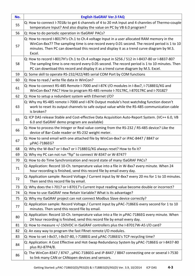
.Getting Started: PAC-7186EG(D)/PEG(D) & I-7188EG(D)/XG(D) Ver. 3.9, 10/2014 ICP DAS .4-3
No. English ISaGRAF Ver.3 FAQ
55 Q: How to connect I-7018z to get 6 channels of 4 to 20 mA Input and 4 channles of Thermo-couple
temperature Input? And also display the value on PC by VB 6.0 program?
56 Q: How to do periodic operation in ISaGRAF PACs?
57
Q: How to record I-8017H’s Ch.1 to Ch.4 voltage Input in a user allocated RAM memory in the WinCon-8xx7? The sampling time is one record every 0.01 second. The record period is 1 to 10 minutes. Then PC can download this record and display it as a trend curve diagram by M.S. Excel.
58 Q: How to record I-8017H’s Ch.1 to Ch.4 voltage input in S256 / 512 in I-8437-80 or I-8837-80?
The sampling time is one record every 0.05 second. The record period is 1 to 10 minutes. Then PC can download this record and display it as a trend curve diagram by M.S. Excel.
59 Q: Some skill to operate RS-232/422/485 serial COM Port by COM functions
60 Q: How to read / write file data in WinCon?
61 Q: How to connect RS-485 Remote I-7000 and I-87K I/O modules in I-8xx7, I-7188EG/XG and
WinCon-8xx7 PAC? How to program RS-485 remote I-7017RC, I-87017RC and I-7018Z?
62 Q: How to setup a redundant system with Ethernet I/O?
63 Q: Why my RS-485 remote I-7000 and I-87K Output module's host watchdog function doesn't
work to reset its output channels to safe output value while the RS-485 communication cable is broken?
65 Q: ICP DAS release Stable and Cost-effective Data Acquisition Auto-Report System. (VC++ 6.0, VB
6.0 and ISaGRAF demo program are available)
66 Q: How to process the Integer or Real value coming from the RS-232 / RS-485 device? Like the
device of Bar-Code reader or RS-232 weight meter.
67 Q: How to send email with one attached file by WinCon-8xx7 or iPAC-8447 / 8847 or
μPAC-7186EG?
68 Q: Why the W-8xx7 or I-8xx7 or I-7188EG/XG always reset? How to fix it?
69 Q: Why my PC can not run “ftp” to connect W-8347 or W-8747?
70 Q: How to do Time Synchronization and record state of many ISaGRAF PACs?
71 Q: Application: Record 10-Ch. temperature value into a file in W-8xx7 every minute. When 24
hour recording is finished, send this record file by email every day.
72 Q: Application sample: Record Voltage / Current input by W-8xx7 every 20 ms for 1 to 10 minutes.
Then send this record file by email.
73 Q: Why does the I-7017 or I-87017's Current Input reading value become double or incorrect?
74 Q: How to use ISaGRAF new Retain Variable? What is its advantage?
75 Q: Why my ISaGRAF project can not connect Modbus Slave device correctly?
77 Q: Application sample: Record Voltage / Current input by μPAC-7186EG every second for 1 to 10
minutes. Then send this record file by email.
80 Q: Application: Record 10-Ch. temperature value into a file in μPAC-7186EG every minute. When
24 hour recording is finished, send this record file by email every day.
81 Q: How to measure +/-150VDC in ISaGRAF controllers plus the I-87017W-A5 I/O card?
82 Q: An easy way to program the fast FRnet remote I/O modules.
83 Q: How to set I-8x37, I-8x37-80, I-7188EG and μPAC-7186EG's TCP recycling time?
84 Q: Application: A Cost Effective and Hot-Swap Redundancy System by μPAC-7186EG or I-8437-80
plus RU-87P4/8.
86 Q: The WinCon-8347 / 8747 , μPAC-7186EG and iP-8447 / 8847 connecting one or several I-7530
to link many CAN or CANopen devices and sensors.
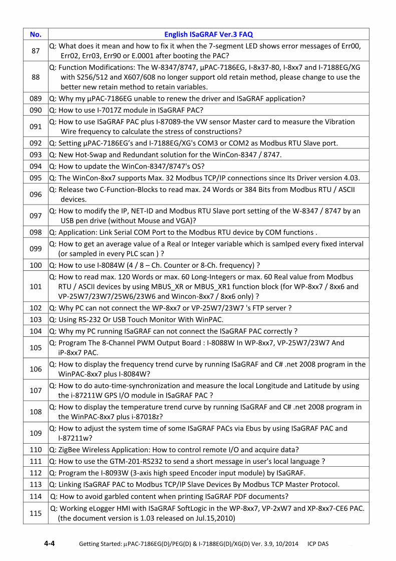
4-4 . Getting Started: PAC-7186EG(D)/PEG(D) & I-7188EG(D)/XG(D) Ver. 3.9, 10/2014 ICP DAS ..
No. English ISaGRAF Ver.3 FAQ
87 Q: What does it mean and how to fix it when the 7-segment LED shows error messages of Err00,
Err02, Err03, Err90 or E.0001 after booting the PAC?
88 Q: Function Modifications: The W-8347/8747, μPAC-7186EG, I-8x37-80, I-8xx7 and I-7188EG/XG
with S256/512 and X607/608 no longer support old retain method, please change to use the better new retain method to retain variables.
089 Q: Why my μPAC-7186EG unable to renew the driver and ISaGRAF application?
090 Q: How to use I-7017Z module in ISaGRAF PAC?
091 Q: How to use ISaGRAF PAC plus I-87089-the VW sensor Master card to measure the Vibration
Wire frequency to calculate the stress of constructions?
092 Q: Setting μPAC-7186EG’s and I-7188EG/XG's COM3 or COM2 as Modbus RTU Slave port.
093 Q: New Hot-Swap and Redundant solution for the WinCon-8347 / 8747.
094 Q: How to update the WinCon-8347/8747's OS?
095 Q: The WinCon-8xx7 supports Max. 32 Modbus TCP/IP connections since Its Driver version 4.03.
096 Q: Release two C-Function-Blocks to read max. 24 Words or 384 Bits from Modbus RTU / ASCII
devices.
097 Q: How to modify the IP, NET-ID and Modbus RTU Slave port setting of the W-8347 / 8747 by an
USB pen drive (without Mouse and VGA)?
098 Q: Application: Link Serial COM Port to the Modbus RTU device by COM functions .
099 Q: How to get an average value of a Real or Integer variable which is samlped every fixed interval
(or sampled in every PLC scan ) ?
100 Q: How to use I-8084W (4 / 8 – Ch. Counter or 8-Ch. frequency) ?
101 Q: How to read max. 120 Words or max. 60 Long-Integers or max. 60 Real value from Modbus
RTU / ASCII devices by using MBUS_XR or MBUS_XR1 function block (for WP-8xx7 / 8xx6 and VP-25W7/23W7/25W6/23W6 and Wincon-8xx7 / 8xx6 only) ?
102 Q: Why PC can not connect the WP-8xx7 or VP-25W7/23W7 's FTP server ?
103 Q: Using RS-232 Or USB Touch Monitor With WinPAC.
104 Q: Why my PC running ISaGRAF can not connect the ISaGRAF PAC correctly ?
105 Q: Program The 8-Channel PWM Output Board : I-8088W In WP-8xx7, VP-25W7/23W7 And
iP-8xx7 PAC.
106 Q: How to display the frequency trend curve by running ISaGRAF and C# .net 2008 program in the
WinPAC-8xx7 plus I-8084W?
107 Q: How to do auto-time-synchronization and measure the local Longitude and Latitude by using
the i-87211W GPS I/O module in ISaGRAF PAC ?
108 Q: How to display the temperature trend curve by running ISaGRAF and C# .net 2008 program in
the WinPAC-8xx7 plus i-87018z?
109 Q: How to adjust the system time of some ISaGRAF PACs via Ebus by using ISaGRAF PAC and
I-87211w?
110 Q: ZigBee Wireless Application: How to control remote I/O and acquire data?
111 Q: How to use the GTM-201-RS232 to send a short message in user's local language ?
112 Q: Program the I-8093W (3-axis high speed Encoder input module) by ISaGRAF.
113 Q: Linking ISaGRAF PAC to Modbus TCP/IP Slave Devices By Modbus TCP Master Protocol.
114 Q: How to avoid garbled content when printing ISaGRAF PDF documents?
115
Q: Working eLogger HMI with ISaGRAF SoftLogic in the WP-8xx7, VP-2xW7 and XP-8xx7-CE6 PAC. (the document version is 1.03 released on Jul.15,2010)
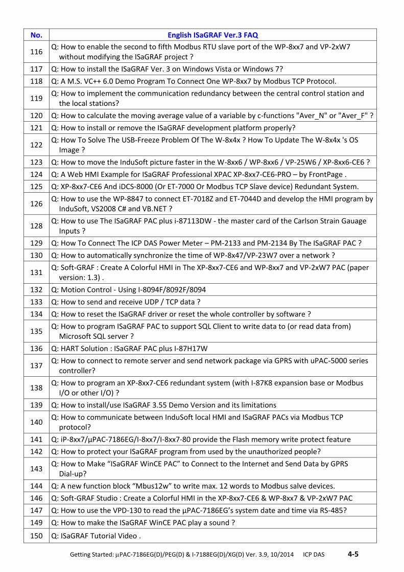
.Getting Started: PAC-7186EG(D)/PEG(D) & I-7188EG(D)/XG(D) Ver. 3.9, 10/2014 ICP DAS .4-5
No. English ISaGRAF Ver.3 FAQ
116
Q: How to enable the second to fifth Modbus RTU slave port of the WP-8xx7 and VP-2xW7 without modifying the ISaGRAF project ?
117 Q: How to install the ISaGRAF Ver. 3 on Windows Vista or Windows 7?
118 Q: A M.S. VC++ 6.0 Demo Program To Connect One WP-8xx7 by Modbus TCP Protocol.
119
Q: How to implement the communication redundancy between the central control station and the local stations?
120 Q: How to calculate the moving average value of a variable by c-functions "Aver_N" or "Aver_F" ?
121 Q: How to install or remove the ISaGRAF development platform properly?
122
Q: How To Solve The USB-Freeze Problem Of The W-8x4x ? How To Update The W-8x4x 's OS Image ?
123 Q: How to move the InduSoft picture faster in the W-8xx6 / WP-8xx6 / VP-25W6 / XP-8xx6-CE6 ?
124 Q: A Web HMI Example for ISaGRAF Professional XPAC XP-8xx7-CE6-PRO – by FrontPage .
125 Q: XP-8xx7-CE6 And iDCS-8000 (Or ET-7000 Or Modbus TCP Slave device) Redundant System.
126
Q: How to use the WP-8847 to connect ET-7018Z and ET-7044D and develop the HMI program by InduSoft, VS2008 C# and VB.NET ?
128
Q: How to use The ISaGRAF PAC plus i-87113DW - the master card of the Carlson Strain Gauage Inputs ?
129 Q: How To Connect The ICP DAS Power Meter – PM-2133 and PM-2134 By The ISaGRAF PAC ?
130 Q: How to automatically synchronize the time of WP-8x47/VP-23W7 over a network ?
131
Q: Soft-GRAF : Create A Colorful HMI in The XP-8xx7-CE6 and WP-8xx7 and VP-2xW7 PAC (paper version: 1.3) .
132 Q: Motion Control - Using I-8094F/8092F/8094
133 Q: How to send and receive UDP / TCP data ?
134 Q: How to reset the ISaGRAF driver or reset the whole controller by software ?
135
Q: How to program ISaGRAF PAC to support SQL Client to write data to (or read data from) Microsoft SQL server ?
136 Q: HART Solution : ISaGRAF PAC plus I-87H17W
137
Q: How to connect to remote server and send network package via GPRS with uPAC-5000 series controller?
138
Q: How to program an XP-8xx7-CE6 redundant system (with I-87K8 expansion base or Modbus I/O or other I/O) ?
139 Q: How to install/use ISaGRAF 3.55 Demo Version and its limitations
140
Q: How to communicate between InduSoft local HMI and ISaGRAF PACs via Modbus TCP protocol?
141 Q: iP-8xx7/μPAC-7186EG/I-8xx7/I-8xx7-80 provide the Flash memory write protect feature
142 Q: How to protect your ISaGRAF program from used by the unauthorized people?
143
Q: How to Make “ISaGRAF WinCE PAC” to Connect to the Internet and Send Data by GPRS Dial-up?
144 Q: A new function block “Mbus12w” to write max. 12 words to Modbus salve devices.
146 Q: Soft-GRAF Studio : Create a Colorful HMI in the XP-8xx7-CE6 & WP-8xx7 & VP-2xW7 PAC
147 Q: How to use the VPD-130 to read the μPAC-7186EG’s system date and time via RS-485?
149 Q: How to make the ISaGRAF WinCE PAC play a sound ?
150 Q: ISaGRAF Tutorial Video .
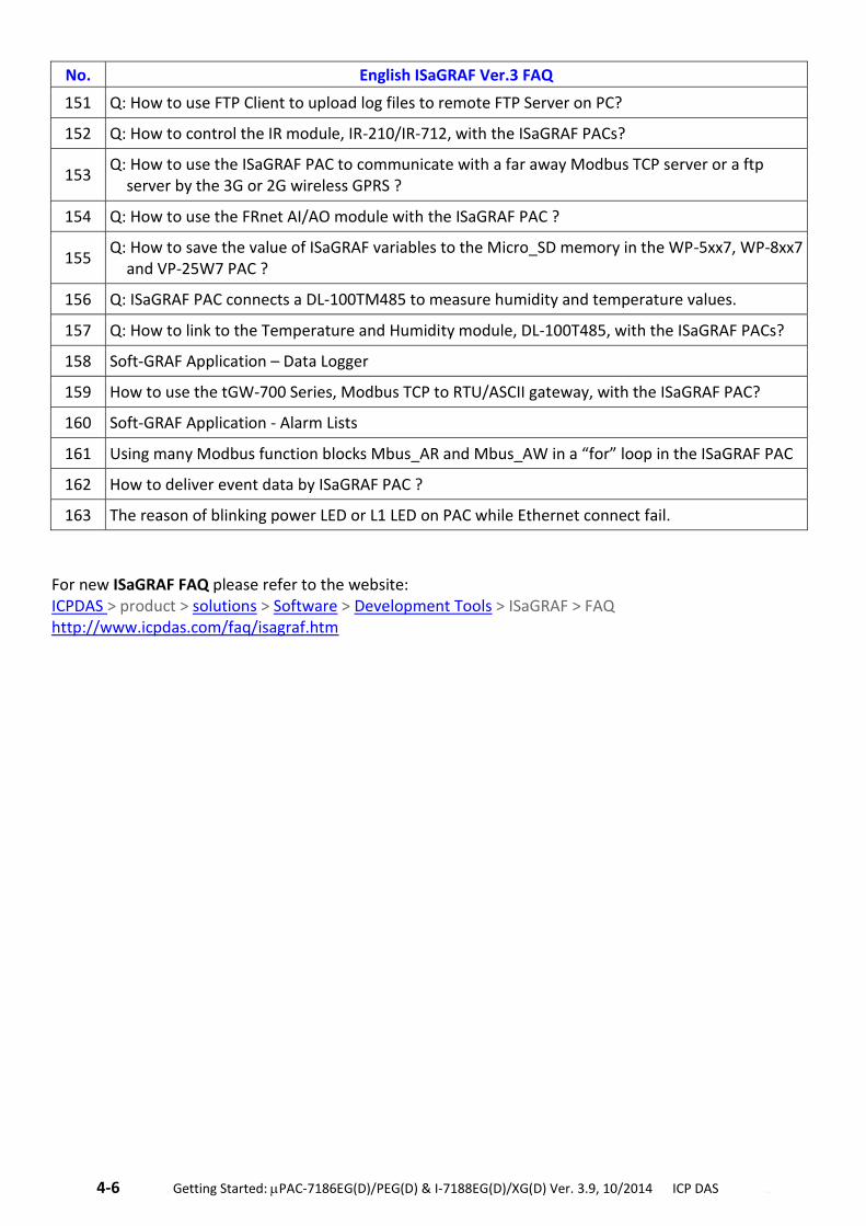
4-6 . Getting Started: PAC-7186EG(D)/PEG(D) & I-7188EG(D)/XG(D) Ver. 3.9, 10/2014 ICP DAS ..
No. English ISaGRAF Ver.3 FAQ
151 Q: How to use FTP Client to upload log files to remote FTP Server on PC?
152 Q: How to control the IR module, IR-210/IR-712, with the ISaGRAF PACs?
153
Q: How to use the ISaGRAF PAC to communicate with a far away Modbus TCP server or a ftp server by the 3G or 2G wireless GPRS ?
154 Q: How to use the FRnet AI/AO module with the ISaGRAF PAC ?
155 Q: How to save the value of ISaGRAF variables to the Micro_SD memory in the WP-5xx7, WP-8xx7
and VP-25W7 PAC ?
156 Q: ISaGRAF PAC connects a DL-100TM485 to measure humidity and temperature values.
157 Q: How to link to the Temperature and Humidity module, DL-100T485, with the ISaGRAF PACs?
158 Soft-GRAF Application – Data Logger
159 How to use the tGW-700 Series, Modbus TCP to RTU/ASCII gateway, with the ISaGRAF PAC?
160 Soft-GRAF Application - Alarm Lists
161 Using many Modbus function blocks Mbus_AR and Mbus_AW in a “for” loop in the ISaGRAF PAC
162 How to deliver event data by ISaGRAF PAC ?
163 The reason of blinking power LED or L1 LED on PAC while Ethernet connect fail.
For new ISaGRAF FAQ please refer to the website: ICPDAS > product > solutions > Software > Development Tools > ISaGRAF > FAQ http://www.icpdas.com/faq/isagraf.htm
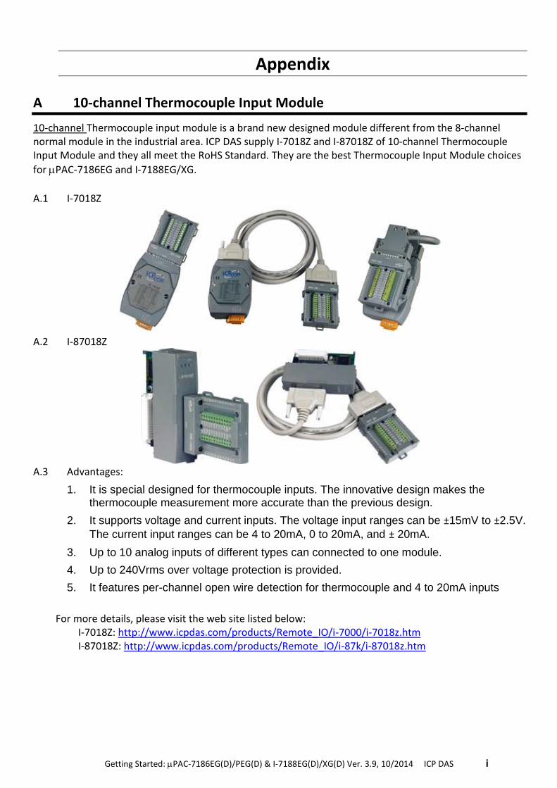
. Getting Started: PAC-7186EG(D)/PEG(D) & I-7188EG(D)/XG(D) Ver. 3.9, 10/2014 ICP DAS .i
Appendix
A 10-channel Thermocouple Input Module
10-channel Thermocouple input module is a brand new designed module different from the 8-channel normal module in the industrial area. ICP DAS supply I-7018Z and I-87018Z of 10-channel Thermocouple Input Module and they all meet the RoHS Standard. They are the best Thermocouple Input Module choices
for PAC-7186EG and I-7188EG/XG.
A.1 I-7018Z
A.2 I-87018Z
A.3 Advantages:
1. It is special designed for thermocouple inputs. The innovative design makes the thermocouple measurement more accurate than the previous design.
2. It supports voltage and current inputs. The voltage input ranges can be ±15mV to ±2.5V.
The current input ranges can be 4 to 20mA, 0 to 20mA, and ± 20mA.
3. Up to 10 analog inputs of different types can connected to one module.
4. Up to 240Vrms over voltage protection is provided.
5. It features per-channel open wire detection for thermocouple and 4 to 20mA inputs
For more details, please visit the web site listed below: I-7018Z: http://www.icpdas.com/products/Remote_IO/i-7000/i-7018z.htm
I-87018Z: http://www.icpdas.com/products/Remote_IO/i-87k/i-87018z.htm
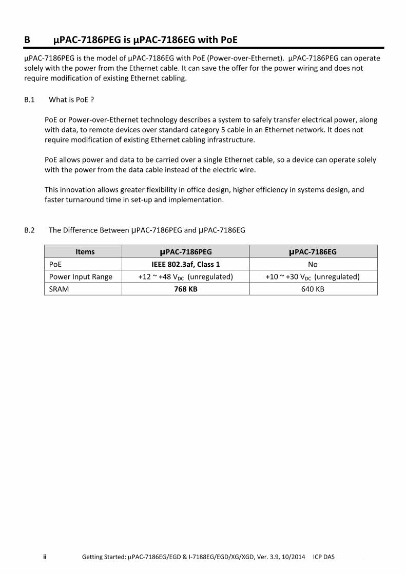
ii Getting Started: PAC-7186EG/EGD & I-7188EG/EGD/XG/XGD, Ver. 3.9, 10/2014 ICP DAS .
B μPAC-7186PEG is μPAC-7186EG with PoE
μPAC-7186PEG is the model of μPAC-7186EG with PoE (Power-over-Ethernet). μPAC-7186PEG can operate solely with the power from the Ethernet cable. It can save the offer for the power wiring and does not require modification of existing Ethernet cabling.
B.1 What is PoE ?
PoE or Power-over-Ethernet technology describes a system to safely transfer electrical power, along with data, to remote devices over standard category 5 cable in an Ethernet network. It does not require modification of existing Ethernet cabling infrastructure. PoE allows power and data to be carried over a single Ethernet cable, so a device can operate solely with the power from the data cable instead of the electric wire. This innovation allows greater flexibility in office design, higher efficiency in systems design, and faster turnaround time in set-up and implementation.
B.2 The Difference Between μPAC-7186PEG and μPAC-7186EG
Items μPAC-7186PEG μPAC-7186EG
PoE IEEE 802.3af, Class 1 No
Power Input Range +12 ~ +48 VDC (unregulated) +10 ~ +30 VDC (unregulated)
SRAM 768 KB 640 KB