GEM detectors activity at the Laboratori Nazionali di Frascati INFN G.BencivenniLNF-INFN.
54
GEM detectors activity at the oratori Nazionali di Frasc INFN G.Bencivenni LNF-INFN
-
Upload
bertina-cross -
Category
Documents
-
view
224 -
download
2
Transcript of GEM detectors activity at the Laboratori Nazionali di Frascati INFN G.BencivenniLNF-INFN.
GEM detectors activityat the
Laboratori Nazionali di FrascatiINFN
G.BencivenniLNF-INFN
2
OUTLINE
Introduction
Planar GEM in LHCb
Cylindrical GEM for Inner Trackers
3
INTRODUCTION
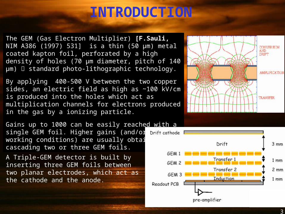
The GEM (Gas Electron Multiplier) [F.Sauli, NIM A386 (1997) 531] is a thin (50 μm) metal coated kapton foil, perforated by a high density of holes (70 μm diameter, pitch of 140 μm) standard photo-lithographic technology.
By applying 400-500 V between the two copper sides, an electric field as high as ~100 kV/cm is produced into the holes which act as multiplication channels for electrons produced in the gas by a ionizing particle.
Gains up to 1000 can be easily reached with a single GEM foil. Higher gains (and/or safer working conditions) are usually obtained by cascading two or three GEM foils.
A Triple-GEM detector is built by inserting three GEM foils between two planar electrodes, which act as the cathode and the anode.
4
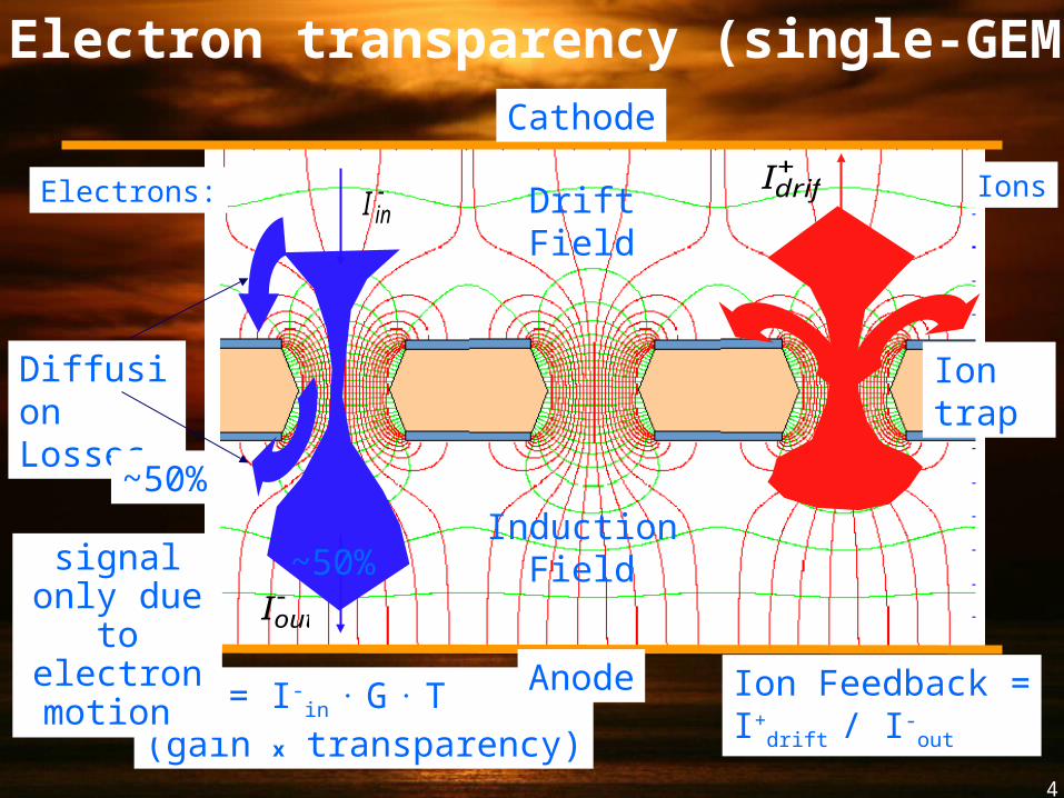
Iin
Iout
Electrons:
Diffusion Losses
I-out = I-in . G
. T(gain x transparency)
Ion Feedback =I+drift / I-out
Ions
Idrift
Ion trap
Cathode
Anode
DriftField
InductionField
~50%
~50%signal only due
to electron motion
Electron transparency (single-GEM)
5
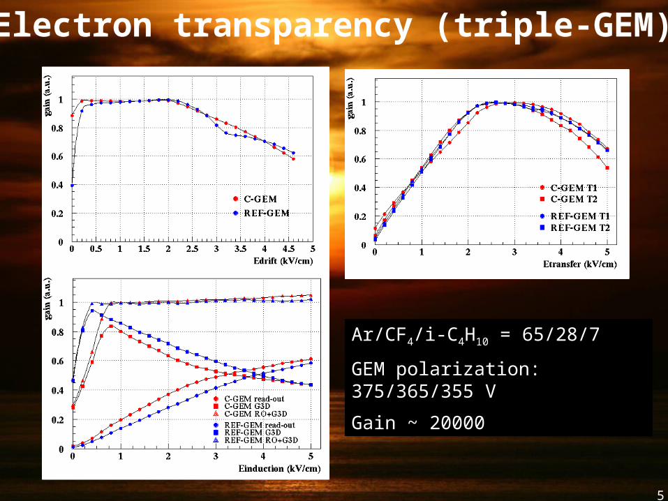
Electron transparency (triple-GEM)
Ar/CF4/i-C4H10 = 65/28/7
GEM polarization: 375/365/355 V
Gain ~ 20000
6
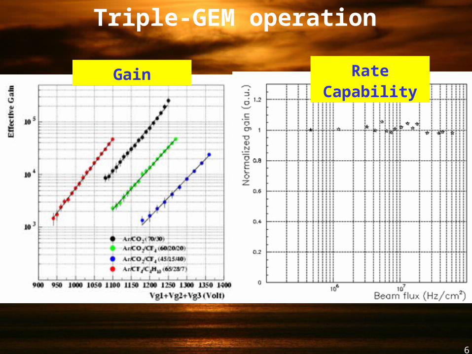
Gain Rate Capability
Triple-GEM operation
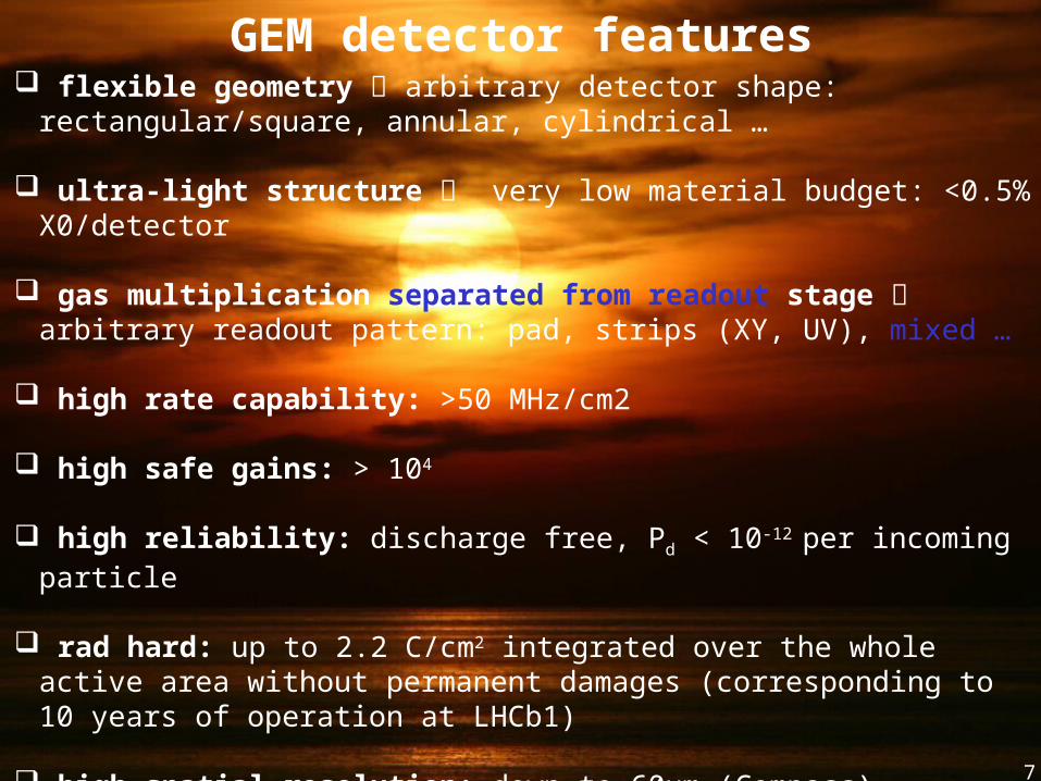
GEM detector features flexible geometry arbitrary detector shape: rectangular/square, annular,
cylindrical …
ultra-light structure very low material budget: <0.5% X0/detector
gas multiplication separated from readout stage arbitrary readout pattern: pad, strips (XY, UV), mixed …
high rate capability: >50 MHz/cm2
high safe gains: > 104
high reliability: discharge free, Pd < 10-12 per incoming particle
rad hard: up to 2.2 C/cm2 integrated over the whole active area without permanent damages (corresponding to 10 years of operation at LHCb1)
high spatial resolution: down to 60µm (Compass)
good time resolution: down to 3 ns (with CF4) 7
8
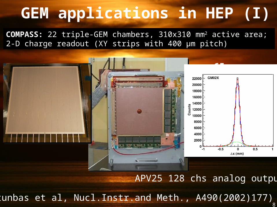
COMPASS: 22 triple-GEM chambers, 310x310 mm2 active area; 2-D charge readout (XY strips with 400 µm pitch)
GEM applications in HEP (I)
(C.Altunbas et al, Nucl.Instr.and Meth., A490(2002)177)
65 μm r.m.s.
APV25 128 chs analog output
9
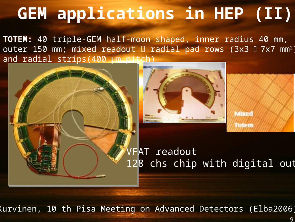
GEM applications in HEP (II)TOTEM: 40 triple-GEM half-moon shaped, inner radius 40 mm, outer 150 mm; mixed readout radial pad rows (3x3 7x7 mm2) and radial strips(400 µm pitch)
VFAT readout128 chs chip with digital output
K. Kurvinen, 10 th Pisa Meeting on Advanced Detectors (Elba2006)
10
GEM in LHCb
collaboration LNF-INFN and CA-INFN(*)
(*)CA-INFN: W. Bonivento, A. Cardini, D. Raspino, B. Saitta
11
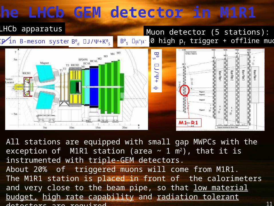
All stations are equipped with small gap MWPCs with the exception of M1R1 station (area ~ 1 m2), that it is instrumented with triple-GEM detectors. About 20% of triggered muons will come from M1R1. The M1R1 station is placed in front of the calorimeters and very close to the beam pipe, so that low material budget, high rate capability and radiation tolerant detectors are required.
LHCb apparatus Muon detector (5 stations): L0 high pT trigger + offline muon ID
The LHCb GEM detector in M1R1
CP in B-meson system B0d J/+K0
S
B0S
J/+ f
B0S m+m-
12
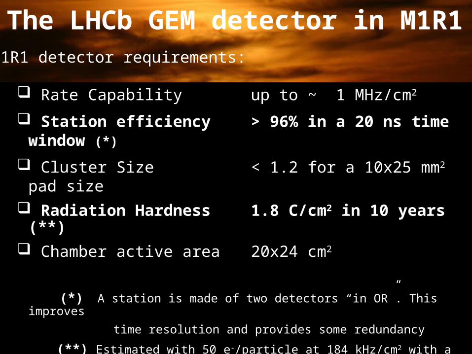
The LHCb GEM detector in M1R1
Rate Capability up to ~ 1 MHz/cm2
Station efficiency > 96% in a 20 ns time window (*)
Cluster Size < 1.2 for a 10x25 mm2 pad size
Radiation Hardness 1.8 C/cm2 in 10 years (**)
Chamber active area 20x24 cm2
(*) A station is made of two detectors “in OR”. This improves
time resolution and provides some redundancy
(**) Estimated with 50 e-/particle at 184 kHz/cm2 with a gain of ~ 6000
M1R1 detector requirements:
13
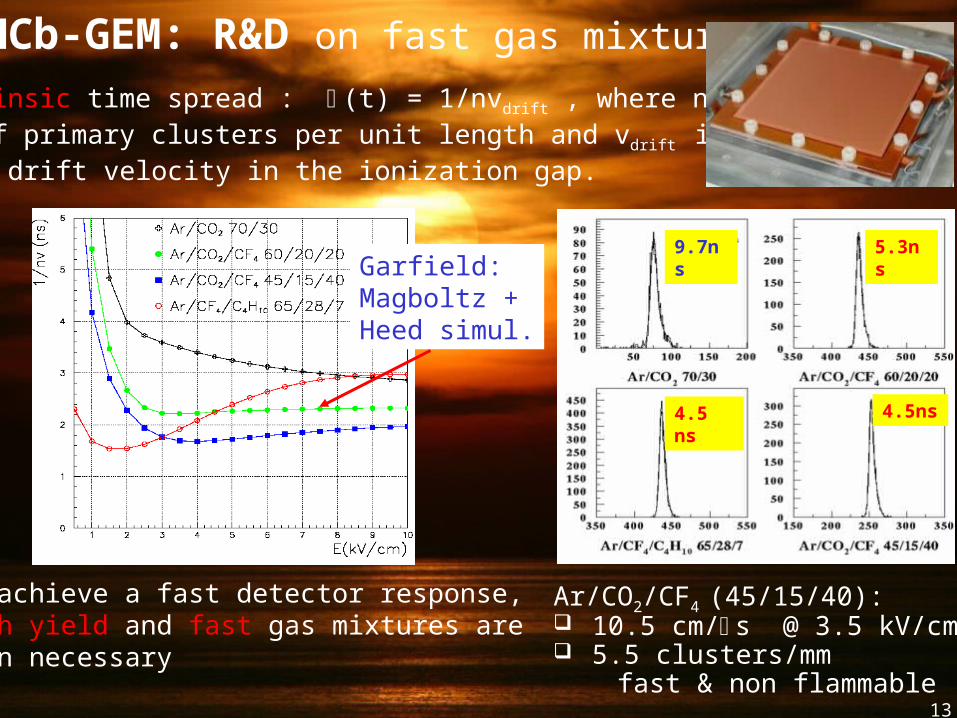
LHCb-GEM: R&D on fast gas mixtures
The intrinsic time spread : s(t) = 1/nvdrift , where n is the number of primary clusters per unit length and vdrift is theelectron drift velocity in the ionization gap.
To achieve a fast detector response, high yield and fast gas mixtures are then necessary
Garfield:Magboltz +Heed simul.
Ar/CO2/CF4 (45/15/40): 10.5 cm/s @ 3.5 kV/cm 5.5 clusters/mm fast & non flammable
9.7ns 5.3ns
4.5 ns 4.5ns
14
Aging measurements: summary
Local Aging:performed with a high intensity 5.9 keV X-ray tube, irradiated area of about 1 mm2 (about 50 GEM holes). Integrated charge 4 C/cm2 25 LHCb years.
Large Area Aging: performed by means of the PSI M1 positive hadron beam, with an intensity up to 300 MHz and an irradiated area of about 15 cm2. Integrated charge 0.5 C/cm2 3 LHCb years.
Global Aging: performed at Casaccia with a 25 kCi 60Co source. Detectors were irradiated at 0.5 16 Gray/h. Integrated charge up to 2.2 C/cm2 12.5 LHCb years.
Detailed information can be found at:P. de Simone et al., “Studies of etching effects on triple-GEM detectors operated with CF4-based gas mixtures”, IEEE Trans. Nucl. Sci. 52 (2005) 2872
15
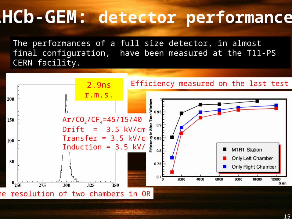
2.9ns r.m.s.
Time resolution of two chambers in OR
Ar/CO2/CF4=45/15/40Drift = 3.5 kV/cmTransfer = 3.5 kV/cmInduction = 3.5 kV/cm
The performances of a full size detector, in almost final configuration, have been measured at the T11-PS CERN facility.
LHCb-GEM: detector performances
Efficiency measured on the last test beam
LHCb – GEMConstruction
16
17
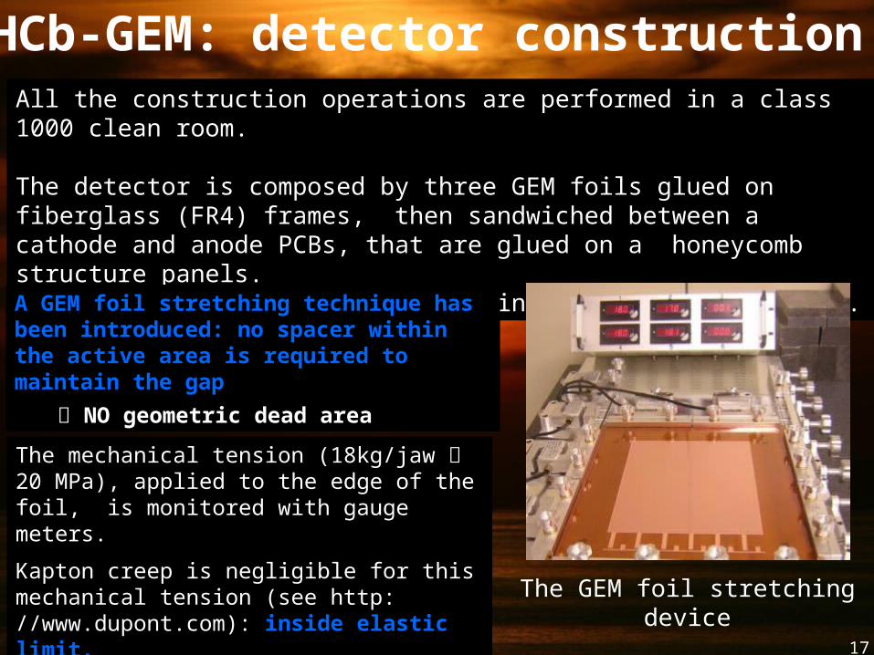
LHCb-GEM: detector constructionAll the construction operations are performed in a class 1000 clean room.
The detector is composed by three GEM foils glued on fiberglass (FR4) frames, then sandwiched between a cathode and anode PCBs, that are glued on a honeycomb structure panels. A M1R1 detector is realized coupling two of such chambers.
A GEM foil stretching technique has been introduced: no spacer within the active area is required to maintain the gap
NO geometric dead area
The GEM foil stretching device
The mechanical tension (18kg/jaw 20 MPa), applied to the edge of the foil, is monitored with gauge meters.
Kapton creep is negligible for this mechanical tension (see http: //www.dupont.com): inside elastic limit.
18
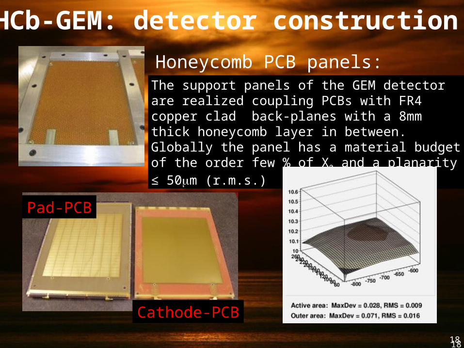
Honeycomb PCB panels:The support panels of the GEM detector are realized coupling PCBs with FR4 copper clad back-planes with a 8mm thick honeycomb layer in between. Globally the panel has a material budget of the order few % of X0 and a planarity ≤ 50mm (r.m.s.)
Measurements of 12 PCB panels: the displacement from an average plane is of the order of 60 mm (rms)
LHCb-GEM: detector construction
Pad-PCB
Cathode-PCB
18
19
LHCb-GEM: detector construction
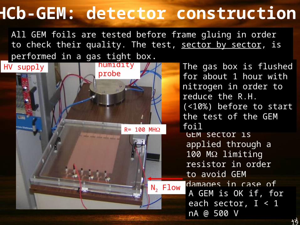
N2 Flow
humidity probe
HV supply
R= 100 MH
All GEM foils are tested before frame gluing in order to check their quality.
The test, sector by sector, is performed in a gas tight box.
The voltage to each GEM sector is applied through a 100 M limiting resistor in order to avoid GEM damages in case of discharges.
The gas box is flushed for about 1 hour with nitrogen in order to reduce the R.H. (<10%) before to start the test of the GEM foil
A GEM is OK if, for each sector, I < 1 nA @ 500 V
19
20
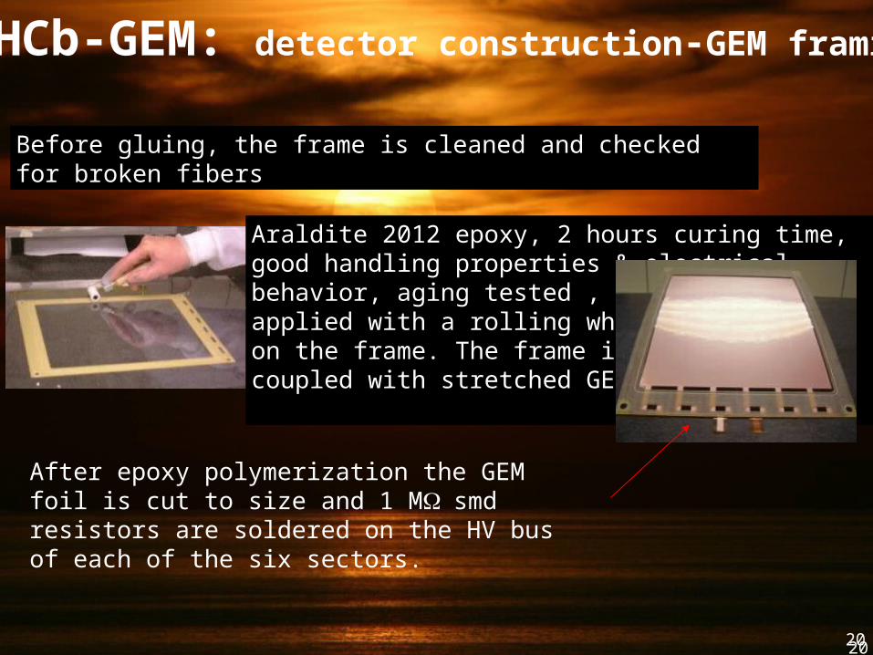
Before gluing, the frame is cleaned and checked for broken fibers
Araldite 2012 epoxy, 2 hours curing time, good handling properties & electricalbehavior, aging tested , is applied with a rolling wheel toolon the frame. The frame is then coupled with stretched GEM foil
After epoxy polymerization the GEM foil is cut to size and 1 M W smd resistors are soldered on the HV bus of each of the six sectors.
LHCb-GEM: detector construction-GEM framing
20
LHCb-GEM: detector construction - assembly (I)
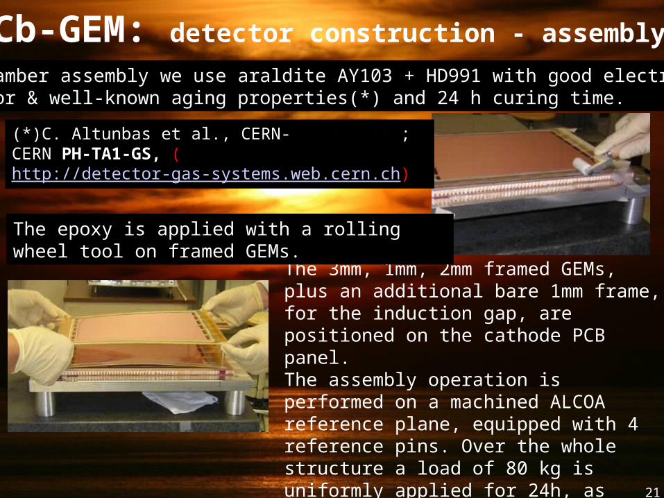
The 3mm, 1mm, 2mm framed GEMs, plus an additional bare 1mm frame, for the induction gap, are positioned on the cathode PCB panel.The assembly operation is performed on a machined ALCOA reference plane, equipped with 4 reference pins. Over the whole structure a load of 80 kg is uniformly applied for 24h, as required for epoxy polymerization.
For chamber assembly we use araldite AY103 + HD991 with good electrical behavior & well-known aging properties(*) and 24 h curing time.
(*)C. Altunbas et al., CERN-EP/2002-008; CERN PH-TA1-GS, (http://detector-gas-systems.web.cern.ch)
The epoxy is applied with a rolling wheel tool on framed GEMs.
21
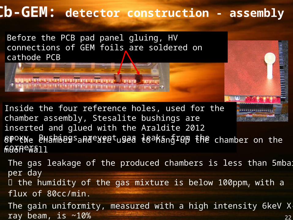
The gas leakage of the produced chambers is less than 5mbar per day the humidity of the gas mixture is below 100ppmV with a flux of 80cc/min.
The gain uniformity, measured with a high intensity 6keV X-ray beam, is ~10%
Before the PCB pad panel gluing, HV connections of GEM foils are soldered on cathode PCB
Inside the four reference holes, used for the chamber assembly, Stesalite bushings are inserted and glued with the Araldite 2012 epoxy. Bushings prevent gas leaks from the corners
of the chamber and are used to hang-up the chamber on the muon wall
LHCb-GEM: detector construction - assembly (II)
22
23
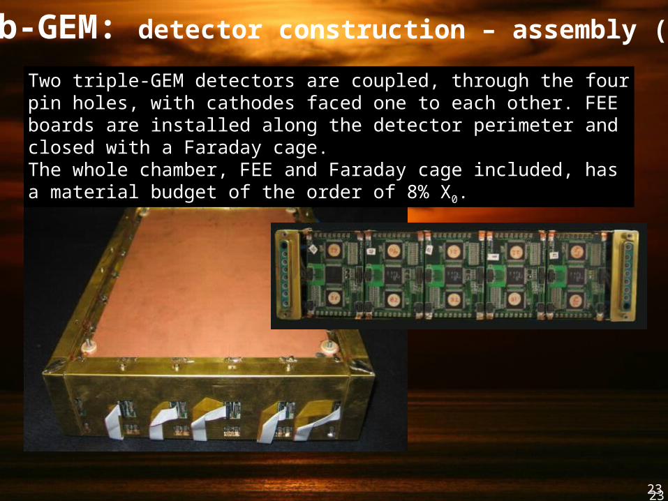
Two triple-GEM detectors are coupled, through the four pin holes, with cathodes faced one to each other. FEE boards are installed along the detector perimeter and closed with a Faraday cage.The whole chamber, FEE and Faraday cage included, has a material budget of the order of 8% X0.
LHCb-GEM: detector construction – assembly (III)
23
24
LHCb-GEM: detector quality test
Gas leak test
N2 Ref chamber
S1 S2
T, P
Chamber to test
Patm
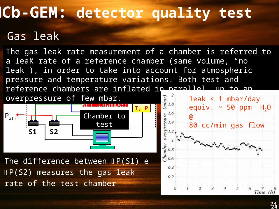
The gas leak rate measurement of a chamber is referred to a leak rate of a reference chamber (same volume, “no leak”), in order to take into account for atmospheric pressure and temperature variations. Both test and reference chambers are inflated in parallel, up to an overpressure of few mbar.
The difference between P(S1) e P(S2)
measures the gas leak rate of the test
chamber
leak < 1 mbar/dayequiv. ~ 50 ppm H2O @ 80 cc/min gas flow
24
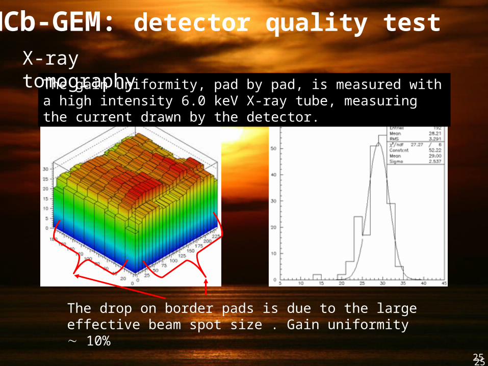
25
The gain uniformity, pad by pad, is measured with a high intensity 6.0 keV X-ray tube, measuring the current drawn by the detector.
The drop on border pads is due to the large effective beam spot size . Gain uniformity 10%
LHCb-GEM: detector quality testX-ray tomography
25
26
Cylindrical GEM VertexR&D
for KLOE-2
27
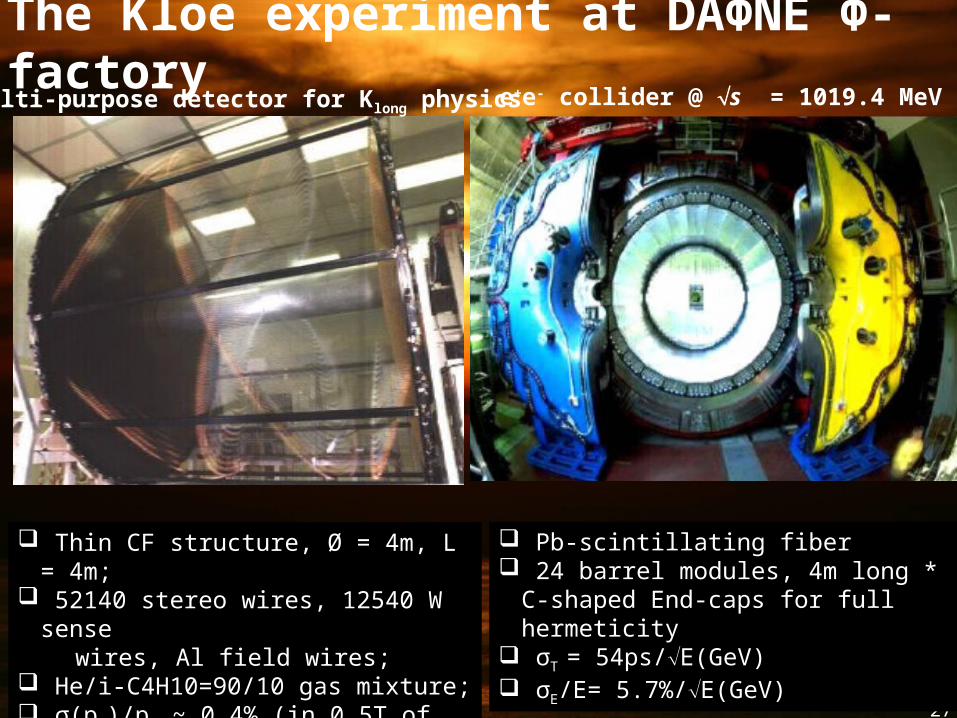
The Kloe experiment at DAΦNE Φ-factory e+e- collider @ s = 1019.4 MeV
Thin CF structure, Ø = 4m, L = 4m; 52140 stereo wires, 12540 W sense wires, Al field wires; He/i-C4H10=90/10 gas mixture; σ(pT)/pT ~ 0.4% (in 0.5T of the SC coil)
Pb-scintillating fiber 24 barrel modules, 4m long * C-shaped
End-caps for full hermeticity σT = 54ps/E(GeV) σE/E= 5.7%/E(GeV)
Multi-purpose detector for Klong physics
28
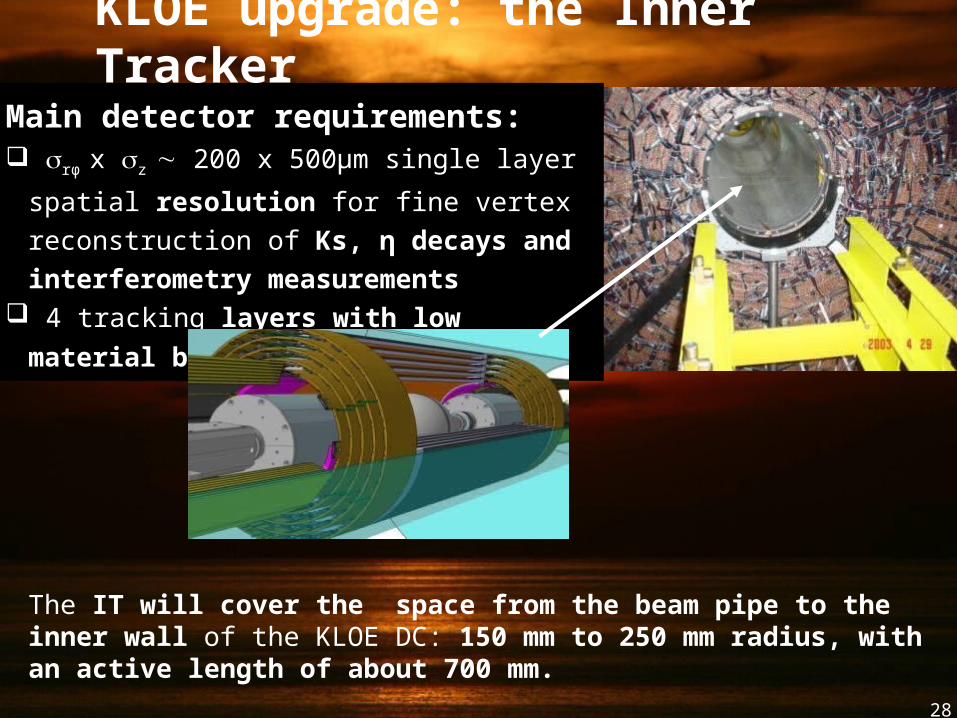
Main detector requirements: rφ x z 200 x 500µm single layer spatial
resolution for fine vertex reconstruction of Ks,
η decays and interferometry measurements 4 tracking layers with low material
budget:1.5%X0
KLOE upgrade: the Inner Tracker
The IT will cover the space from the beam pipe to the inner wall of the KLOE DC: 150 mm to 250 mm radius, with an active length of about 700 mm.
29
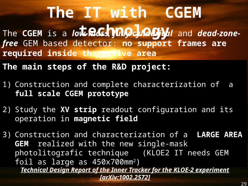
The IT with CGEM technology
The main steps of the R&D project:
1) Construction and complete characterization of a full scale CGEM prototype
2) Study the XV strip readout configuration and its operation in magnetic field
3) Construction and characterization of a LARGE AREA GEM realized with the new single-mask photolitografic technique (KLOE2 IT needs GEM foil as large as 450x700mm2)
The CGEM is a low-mass, fully cylindrical and dead-zone-free GEM based detector: no support frames are required inside the active area
Technical Design Report of the Inner Tracker for the KLOE-2 experiment [arXiv:1002.2572]
30
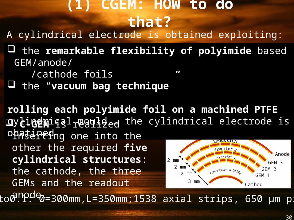
(1) CGEM: HOW to do that?
Proto0.1: Ø=300mm,L=350mm;1538 axial strips, 650 µm pitch
3 mm
2 mm2 mm
2 mm
Cathode
GEM 1GEM 2
GEM 3
Anode
Read-out
Cylindrical Triple GEM
A cylindrical electrode is obtained exploiting:
the remarkable flexibility of polyimide based GEM/anode/ /cathode foils the “vacuum bag technique”
rolling each polyimide foil on a machined PTFE cylindrical mould … the cylindrical electrode is obatined C-GEM is realized inserting one
into the other the required five cylindrical structures: the cathode, the three GEMs and the readout anode.
31
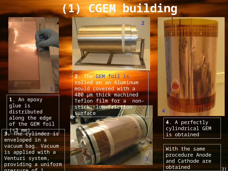
1. An epoxy glue is distributed along the edge of the GEM foil (<3 mm)
3. The cylinder is enveloped in a vacuum bag. Vacuum is applied with a Venturi system, providing a uniform pressure of 1 kg/cm2
(1) CGEM building procedure
4. A perfectly cylindrical GEM is obtained
4
3
2
1
With the same procedure Anode and Cathode are obtained
2. The GEM foil is rolled on an Aluminum mould covered with a 400 µm thick machined Teflon film for a non-stick, low-friction surface
32
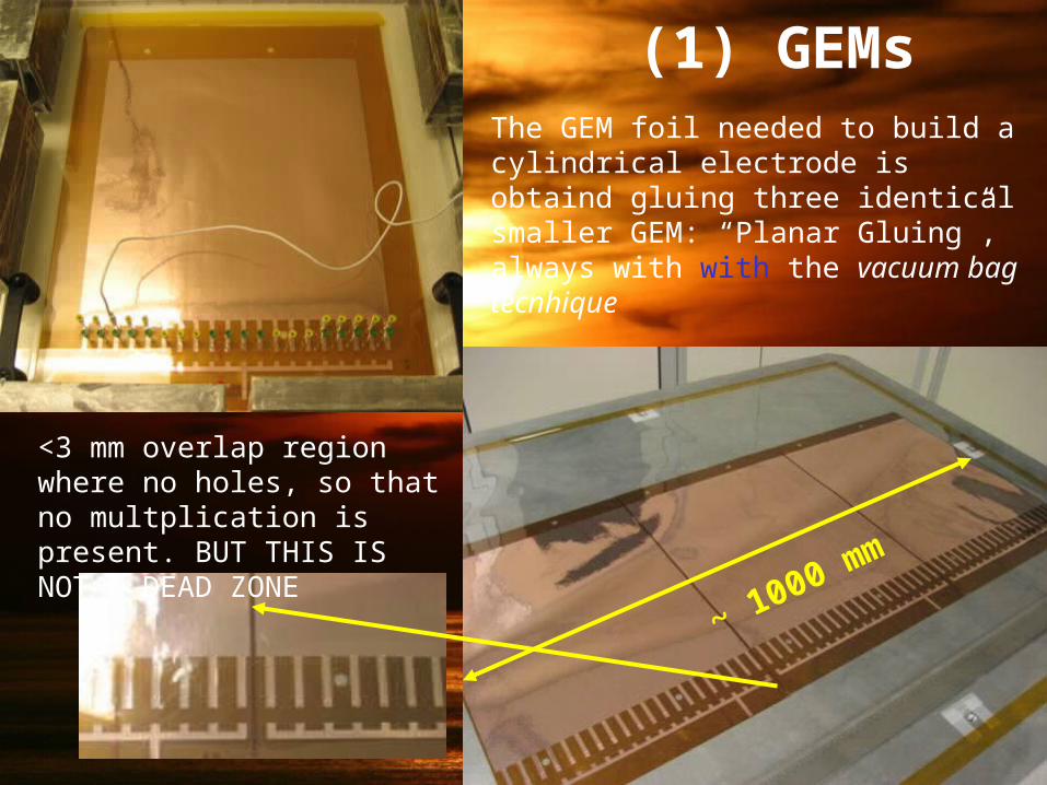
(1) GEMsThe GEM foil needed to build a cylindrical electrode is obtaind gluing three identical smaller GEM: “Planar Gluing”, always with with the vacuum bag tecnhique
<3 mm overlap region where no holes, so that no multplication is present. BUT THIS IS NOT A DEAD ZONE
~ 1000 mm
33
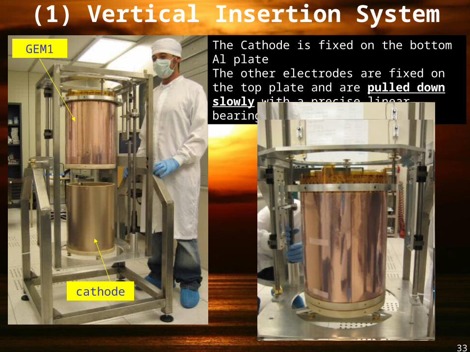
(1) Vertical Insertion SystemGEM1
cathode
The Cathode is fixed on the bottom Al plateThe other electrodes are fixed on the top plate and are pulled down slowly with a precise linear bearing equipment
34
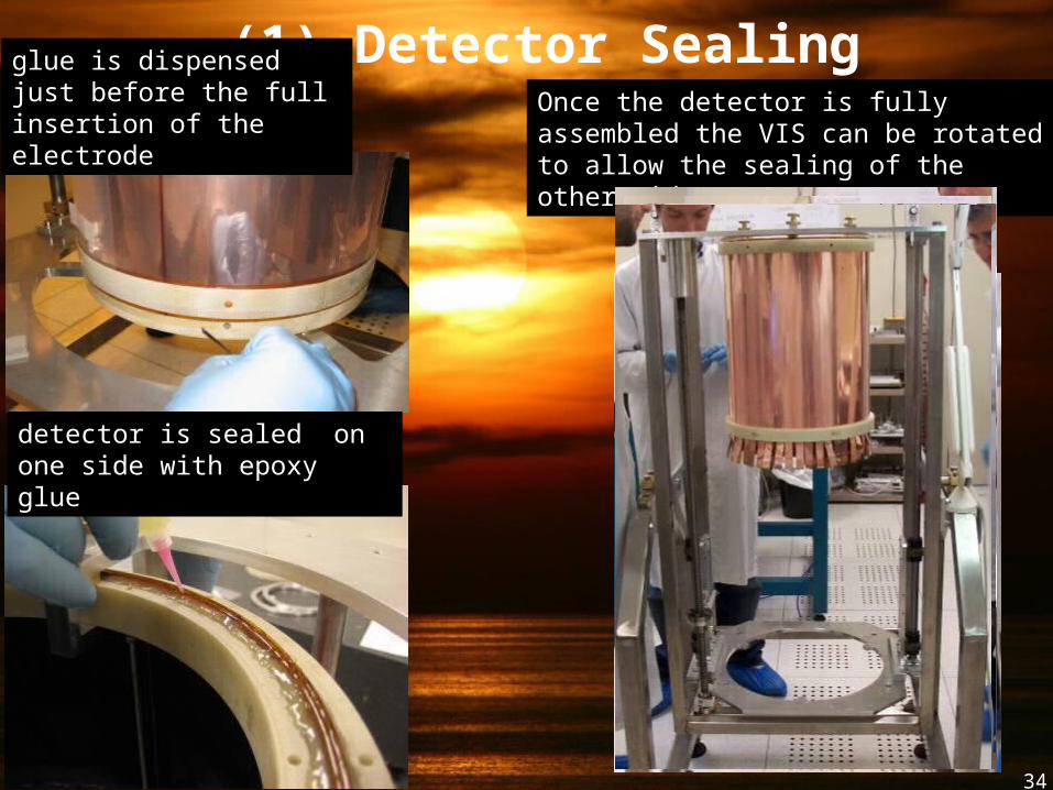
(1) Detector SealingOnce the detector is fully assembled the VIS can be rotated to allow the sealing of the other side…
detector is sealed on one side with epoxy glue
glue is dispensed just before the full insertion of the electrode
35
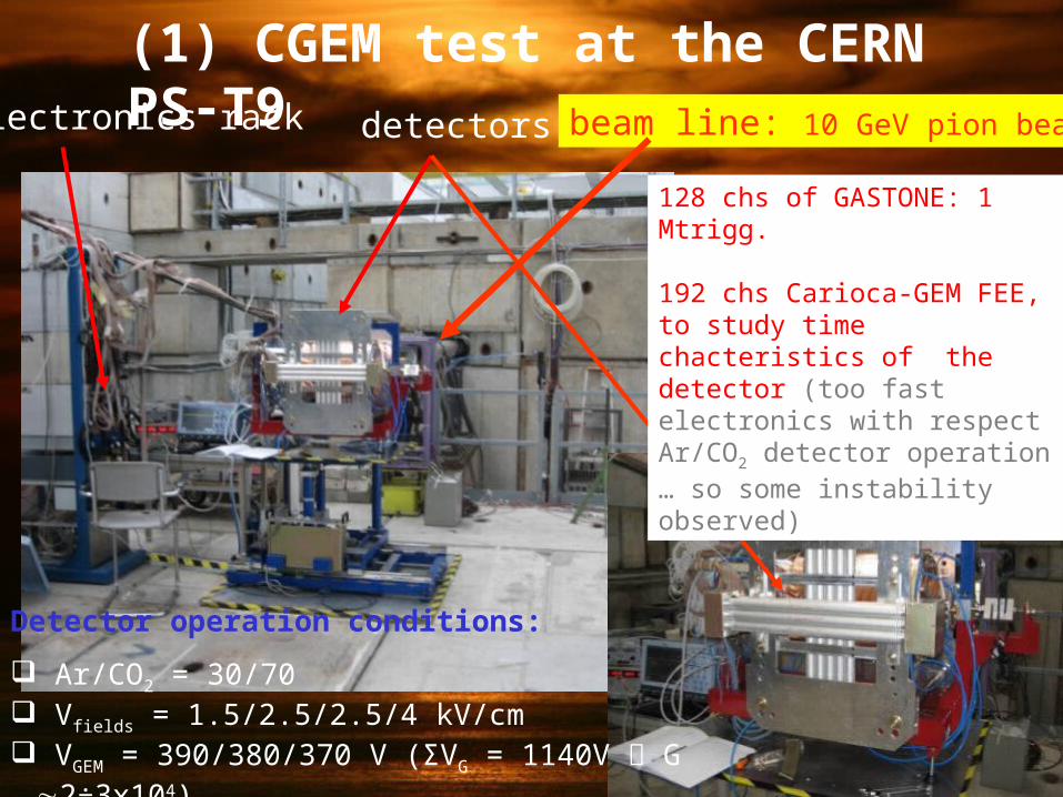
detectorselectronics rack beam line: 10 GeV pion beam
128 chs of GASTONE: 1 Mtrigg.
192 chs Carioca-GEM FEE, to study time chacteristics of the detector (too fast electronics with respect Ar/CO2 detector operation … so some instability observed)
Detector operation conditions:
Ar/CO2 = 30/70 Vfields = 1.5/2.5/2.5/4 kV/cm VGEM = 390/380/370 V (ΣVG = 1140V G 2÷3x10⁴)
(1) CGEM test at the CERN PS-T9
36
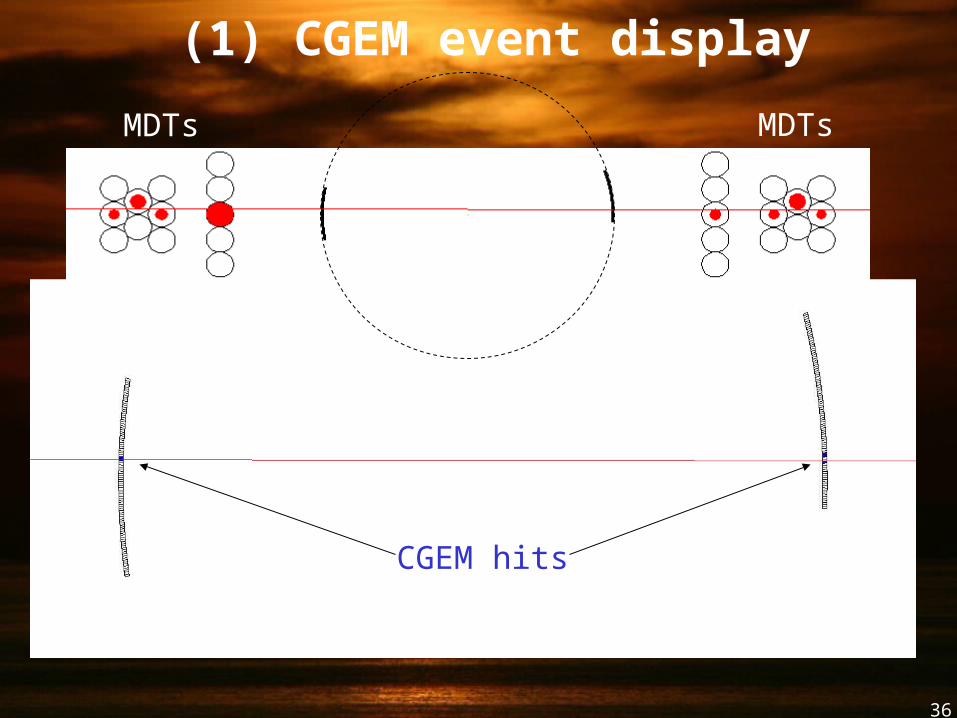
(1) CGEM event display
MDTs MDTs
CGEM hits
37
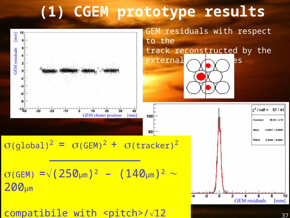
(1) CGEM prototype resultsGEM residuals with respect to the track reconstructed by the external drift tubes
(global)2 = (GEM)2 + (tracker)2
(GEM) =(250µm)2 – (140µm)2 200µm
compatibile with <pitch>/12 (digital readout)
38
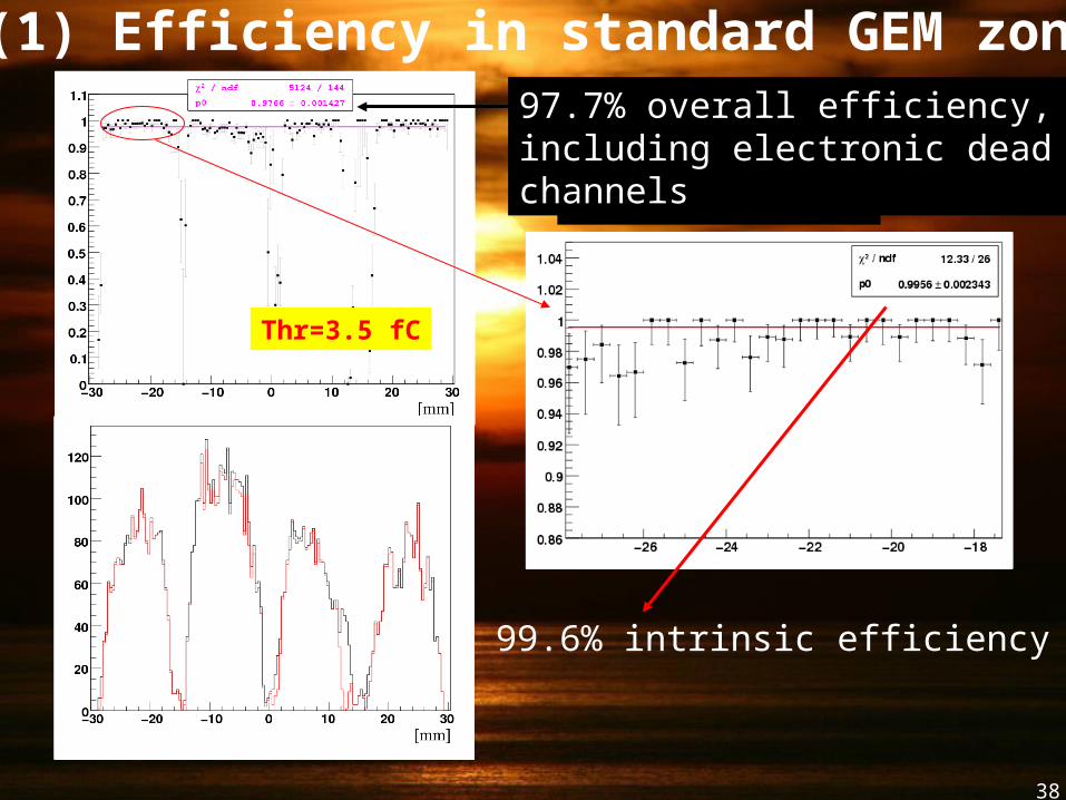
(1) Efficiency in standard GEM zone
Without fee holes
Thr=3.5 fC
97.7% overall efficiency, including electronic dead channels
99.6% intrinsic efficiency
39
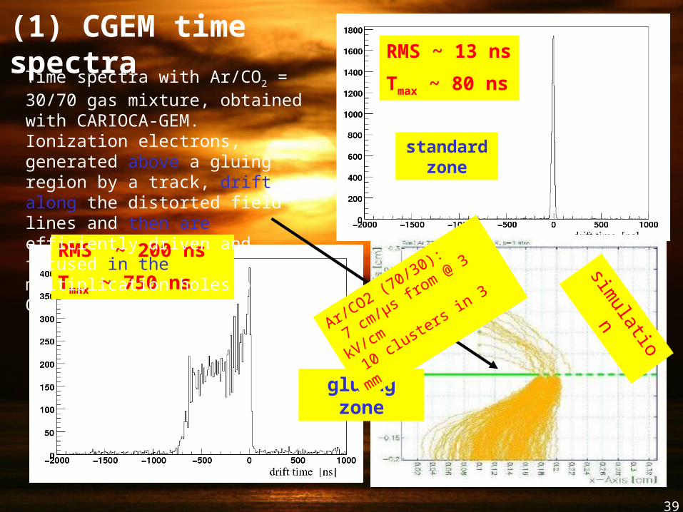
RMS ~ 13 ns
Tmax ~ 80 ns
RMS ~ 200 ns
Tmax ~ 750 ns
standard zone
gluing zone
(1) CGEM time spectra
simulation
Time spectra with Ar/CO2 = 30/70 gas mixture, obtained with CARIOCA-GEM. Ionization electrons, generated above a gluing region by a track, drift along the distorted field lines and then are efficiently driven and focused in the multiplication holes of the GEM.
Ar/CO2 (7
0/30):
7 cm/μs from @
3 kV/cm
10 clusters in 3 m
m
40
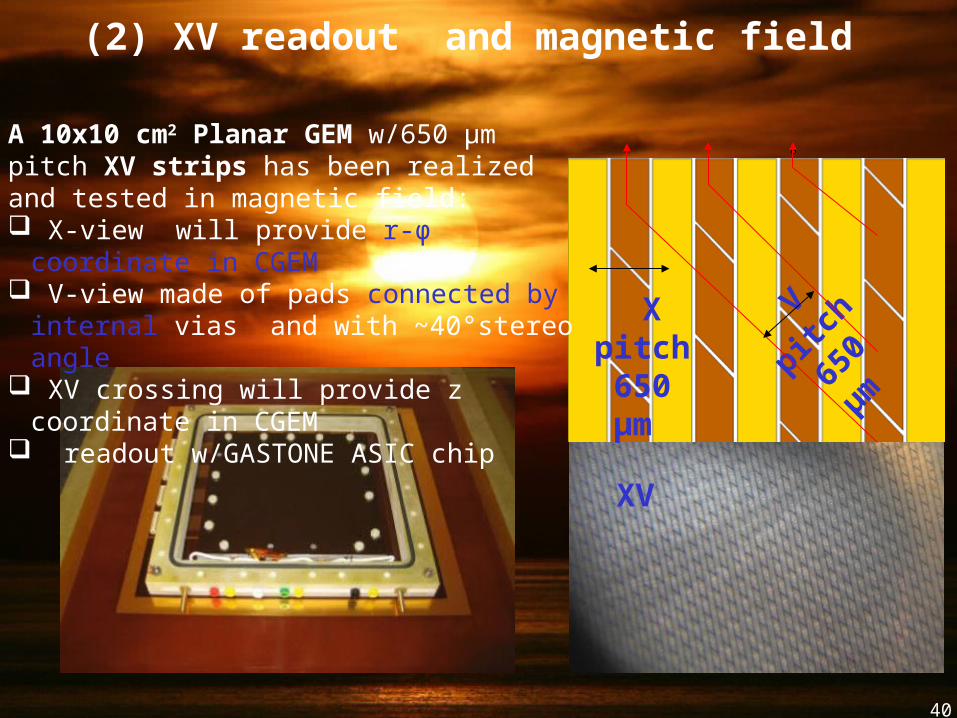
(2) XV readout and magnetic field
40°
X pitch 650 µm
V
pitch
650
µm
XV
A 10x10 cm2 Planar GEM w/650 µm pitch XV strips has been realized and tested in magnetic field: X-view will provide r-φ coordinate in CGEM V-view made of pads connected by internal
vias and with ~40°stereo angle XV crossing will provide z coordinate in
CGEM readout w/GASTONE ASIC chip
41
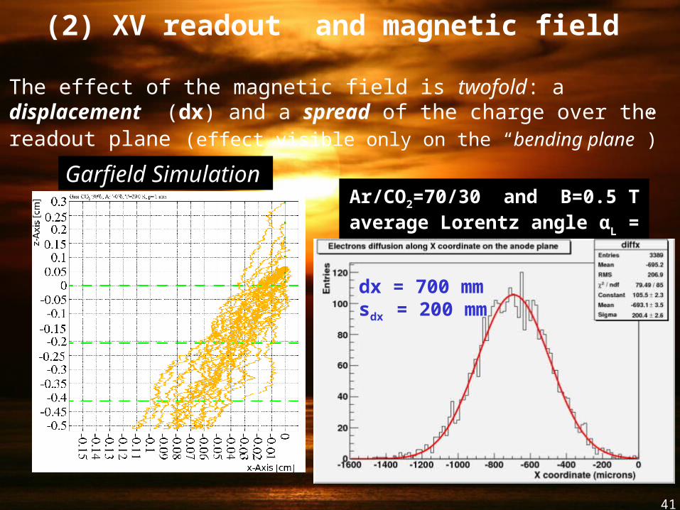
Ar/CO2=70/30 and B=0.5 Taverage Lorentz angle α
L = 8°- 9°
The effect of the magnetic field is twofold: a displacement (dx) and a spread of the charge over the readout plane (effect visible only on the “bending plane”)
(2) XV readout and magnetic field
Garfield Simulation
dx = 700 mmsdx = 200 mm
42
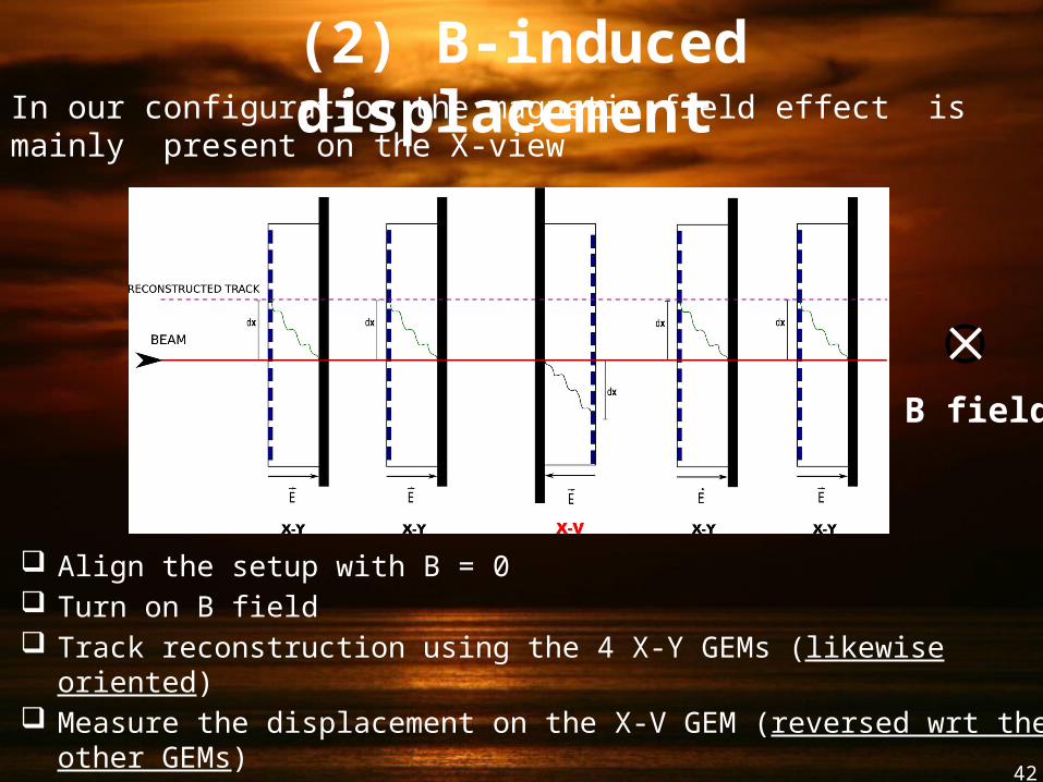
Align the setup with B = 0 Turn on B field Track reconstruction using the 4 X-Y GEMs (likewise oriented) Measure the displacement on the X-V GEM (reversed wrt the other GEMs)
D = 2 dx tan(θL) = D ∕ 2r ( r = effective detector thickness)
B field
(2) B-induced displacement In our configuration the magnetic field effect is mainly present on the X-view
43
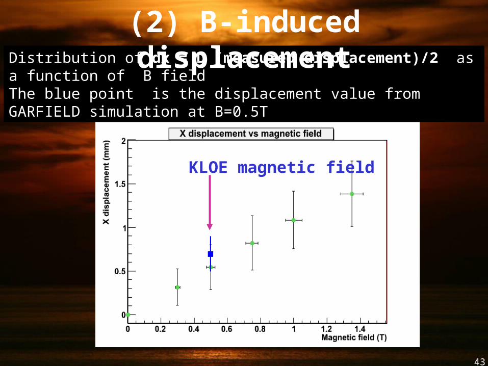
KLOE magnetic field
Distribution of dx = D (measured displacement)/2 as a function of B field The blue point is the displacement value from GARFIELD simulation at B=0.5T
(2) B-induced displacement
44
KLOE B - field
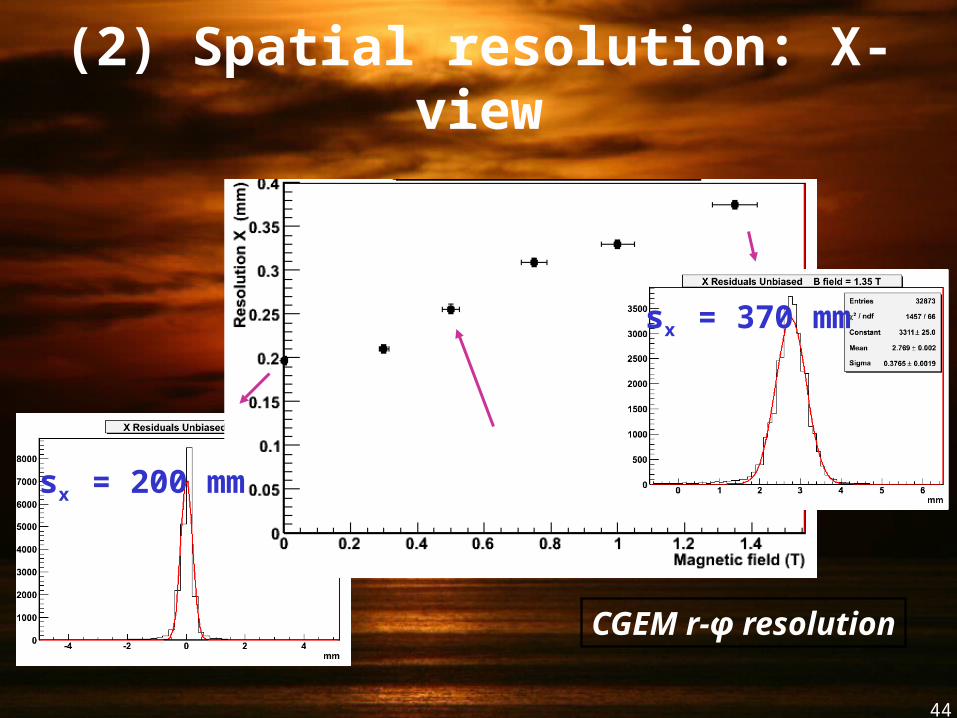
CGEM r-φ resolution
(2) Spatial resolution: X-view
sx = 200 mm
sx = 370 mm
45
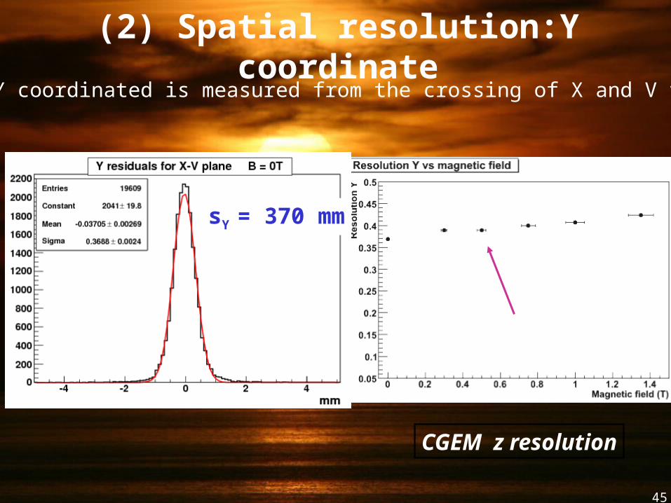
(2) Spatial resolution:Y coordinate
The Y coordinated is measured from the crossing of X and V views
KLOE B - field
CGEM z resolution
sY = 370 mm
46
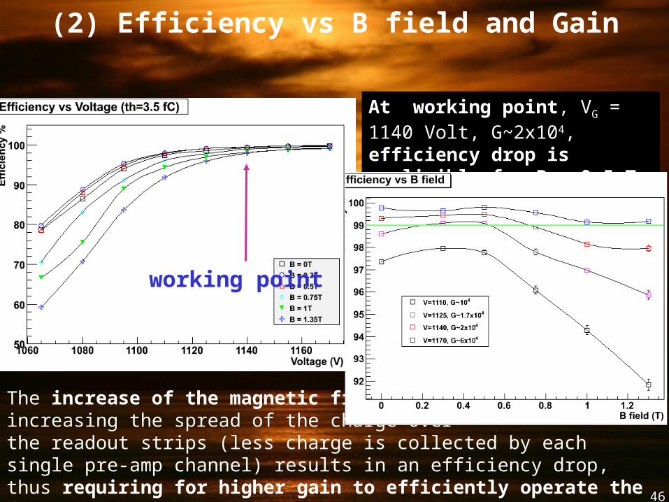
(2) Efficiency vs B field and Gain
working point
At working point, VG = 1140 Volt, G~2x10⁴, efficiency drop is negligible for B < 0.5 T
The increase of the magnetic field, increasing the spread of the charge over the readout strips (less charge is collected by each single pre-amp channel) results in an efficiency drop, thus requiring for higher gain to efficiently operate the detector.
47
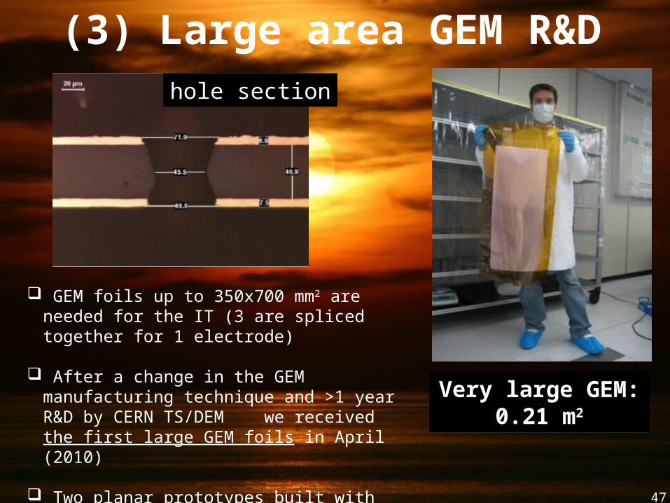
(3) Large area GEM R&D
Very large GEM: 0.21 m2
Very large GEM: 0.21 m2
GEM foils up to 350x700 mm2 are needed for the IT (3 are spliced together for 1 electrode)
After a change in the GEM manufacturing technique and >1 year R&D by CERN TS/DEM we received the first large GEM foils in April (2010)
Two planar prototypes built with the final dimensions of IT foil for pre-production test
hole section
48
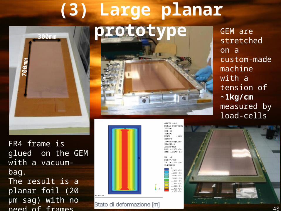
300mm
700m
mGEM are stretched on a custom-made machine with a tension of ~1kg/cm measured by load-cells
FR4 frame is glued on the GEM with a vacuum-bag.The result is a planar foil (20 µm sag) with no need of frames inside the active area.
(3) Large planar prototype
49
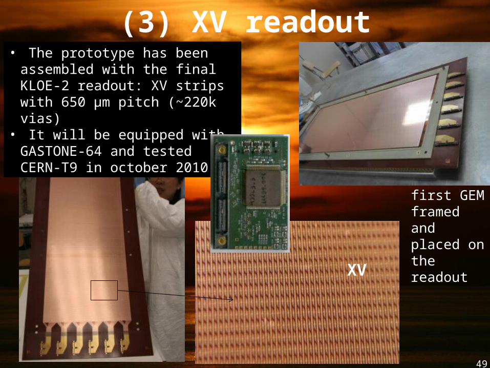
(3) XV readout• The prototype has been
assembled with the final KLOE-2 readout: XV strips with 650 μm pitch (~220k vias)
• It will be equipped with GASTONE-64 and tested CERN-T9 in october 2010
first GEM framed and placed on the readout
XV
50
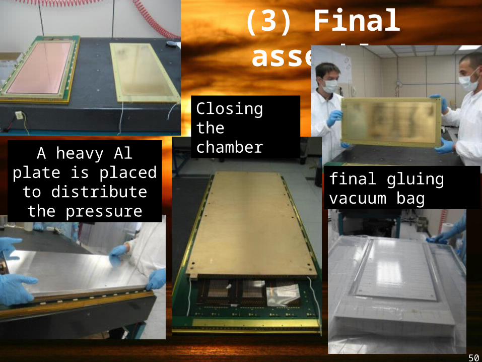
(3) Final assembly
Closing the chamber
A heavy Al plate is placed to distribute
the pressurefinal gluing vacuum bag
51
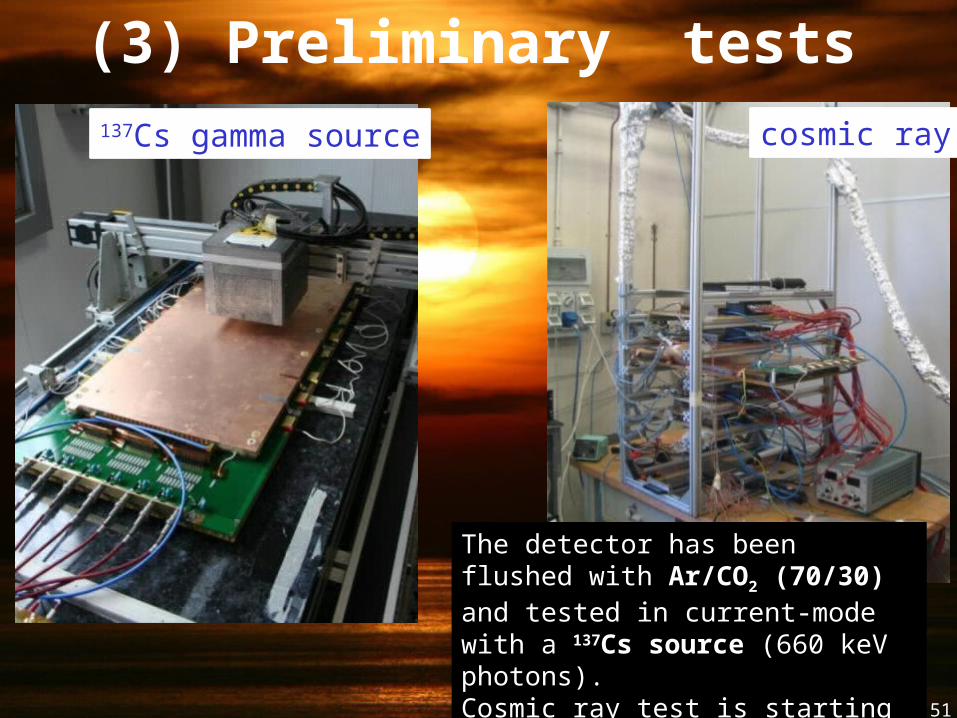
(3) Preliminary tests137Cs gamma source cosmic ray
The detector has been flushed with Ar/CO2 (70/30) and tested in current-mode with a 137Cs source (660 keV photons). Cosmic ray test is starting soon.
52
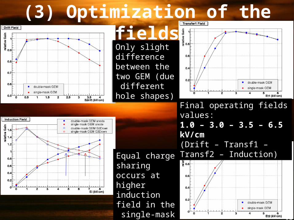
(3) Optimization of the fields
Only slight difference between the two GEM (due different hole shapes)
Equal charge sharing occurs at higher induction field in the single-mask
4.8 6.5
Final operating fields values:1.0 – 3.0 – 3.5 – 6.5 kV/cm(Drift – Transf1 – Transf2 – Induction)
53
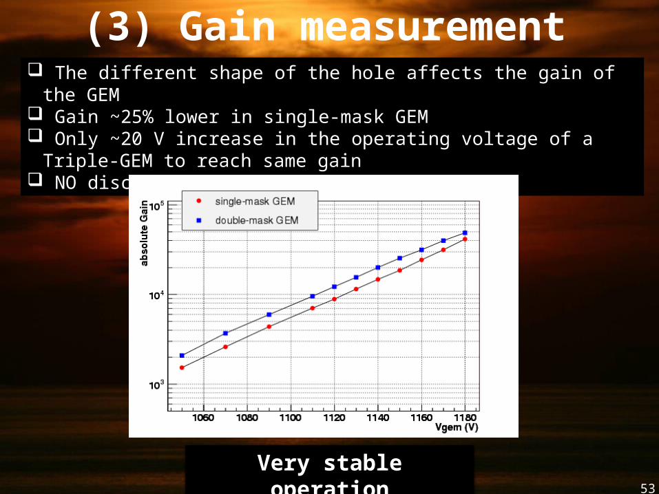
(3) Gain measurement The different shape of the hole affects the gain of the GEM Gain ~25% lower in single-mask GEM Only ~20 V increase in the operating voltage of a Triple-GEM to reach
same gain NO discharge observed up to 40000 gain
Very stable operation
54
Conclusions
Among Micro-Pattern Gas Detectors, the GEM technology has demonstrated great robustness, long-term stability of operation, remarkable flexibility and capability to accomplish different tasks in harsh environments
Planar GEMs are installed and running in LHCb
R&D on a innovative Cylindrical GEM detector as very low-mass inner tracker for the KLOE experiment has been completed