GCD 12 JL - m.media-amazon.com
14
Robert Bosch GmbH Power Tools Division 70745 Leinfelden-Echterdingen Germany www.bosch-pt.com 1 609 92A 08W (2013.05) PS / 252 EURO GCD 12 JL Professional de Originalbetriebsanleitung en Original instructions fr Notice originale es Manual original pt Manual original it Istruzioni originali nl Oorspronkelijke gebruiksaanwij- zing da Original brugsanvisning sv Bruksanvisning i original no Original driftsinstruks fi Alkuperäiset ohjeet el Πρωτότυπο οδηγιών χρήσης tr Orijinal işletme talimatı pl Instrukcja oryginalna cs Původní návod k používání sk Pôvodný návod na použitie hu Eredeti használati utasítás ru Оригинальное руководство по эк- сплуатации uk Оригінальна інструкція з експлуатації kk Пайдалану нұсқаулығының түпнұсқасы ro Instrucţiuni originale bg Оригинална инструкция mk Оригинално упатство за работа sr Originalno uputstvo za rad sl Izvirna navodila hr Originalne upute za rad et Algupärane kasutusjuhend lv Instrukcijas oriģinālvalodā lt Originali instrukcija ar fa OBJ_BUCH-1938-001.book Page 1 Wednesday, May 29, 2013 1:42 PM
Transcript of GCD 12 JL - m.media-amazon.com
Robert Bosch GmbHPower Tools Division70745 Leinfelden-EchterdingenGermany
www.bosch-pt.com
1 609 92A 08W (2013.05) PS / 252 EURO
GCD 12 JL Professional
de Originalbetriebsanleitungen Original instructionsfr Notice originalees Manual originalpt Manual originalit Istruzioni originalinl Oorspronkelijke gebruiksaanwij-
zingda Original brugsanvisningsv Bruksanvisning i originalno Original driftsinstruksfi Alkuperäiset ohjeetel Πρωτότυπο οδηγιών χρήσης
tr Orijinal işletme talimatıpl Instrukcja oryginalnacs Původní návod k používánísk Pôvodný návod na použitiehu Eredeti használati utasításru Оригинальное руководство по эк-
сплуатацииuk Оригінальна інструкція з
експлуатаціїkk Пайдалану нұсқаулығының
түпнұсқасы ro Instrucţiuni originalebg Оригинална инструкция
mk Оригинално упатство за работаsr Originalno uputstvo za radsl Izvirna navodilahr Originalne upute za radet Algupärane kasutusjuhendlv Instrukcijas oriģinālvalodālt Originali instrukcijaarfa
OBJ_BUCH-1938-001.book Page 1 Wednesday, May 29, 2013 1:42 PM
| 3
Bosch Power Tools 1 609 92A 08W | (29.5.13)
3
4
5
6
7
2
101112 9
1
13
14
GCD 12 JL
8
OBJ_BUCH-1938-001.book Page 3 Wednesday, May 29, 2013 1:42 PM
1 609 92A 08W | (29.5.13) Bosch Power Tools
4 |
17
18
20
21
22
23
24
19
1615
23 25
GCD 12 JL
16
OBJ_BUCH-1938-001.book Page 4 Wednesday, May 29, 2013 1:42 PM
| 5
Bosch Power Tools 1 609 92A 08W | (29.5.13)
2323
3
27
21
26
12
293031
32
28
22
4
22
21
A B1
B2 B3
B4
OBJ_BUCH-1938-001.book Page 5 Wednesday, May 29, 2013 1:42 PM
1 609 92A 08W | (29.5.13) Bosch Power Tools
6 |
14
1011
33
34
13
7 8 9
6
19
C D
E F
G
OBJ_BUCH-1938-001.book Page 6 Wednesday, May 29, 2013 1:42 PM
| 7
Bosch Power Tools 1 609 92A 08W | (29.5.13)
1
24
19
117 171
35
H I
J
K1 K2
OBJ_BUCH-1938-001.book Page 7 Wednesday, May 29, 2013 1:42 PM
1 609 92A 08W | (29.5.13) Bosch Power Tools
8 |
6
1333
36
L
OBJ_BUCH-1938-001.book Page 8 Wednesday, May 29, 2013 1:42 PM
English | 17
Bosch Power Tools 1 609 92A 08W | (29.5.13)
EnglishSafety NotesGeneral Power Tool Safety Warnings
When using electric tools basic safety precautions should always be followed
to reduce the risk of fire, electric shock and personal injury in-cluding the following.Read all these instructions before attempting to operate this product and save these instructions.The term “power tool” in the warnings refers to your mains-operated (corded) power tool or battery-operated (cordless) power tool.
Work area safety Keep work area clean and well lit. Cluttered or dark areas
invite accidents. Do not operate power tools in explosive atmospheres,
such as in the presence of flammable liquids, gases or dust. Power tools create sparks which may ignite the dust or fumes.
Keep children and bystanders away while operating a power tool. Distractions can cause you to lose control.
Electrical safety Power tool plugs must match the outlet. Never modify
the plug in any way. Do not use any adapter plugs with earthed (grounded) power tools. Unmodified plugs and matching outlets will reduce risk of electric shock.
Avoid body contact with earthed or grounded surfaces, such as pipes, radiators, ranges and refrigerators. There is an increased risk of electric shock if your body is earthed or grounded.
Do not expose power tools to rain or wet conditions. Water entering a power tool will increase the risk of electric shock.
Do not abuse the cord. Never use the cord for carrying, pulling or unplugging the power tool. Keep cord away from heat, oil, sharp edges and moving parts. Damaged or entangled cords increase the risk of electric shock.
When operating a power tool outdoors, use an exten-sion cord suitable for outdoor use. Use of a cord suitable for outdoor use reduces the risk of electric shock.
If operating a power tool in a damp location is unavoid-able, use a residual current device (RCD) protected supply. Use of an RCD reduces the risk of electric shock.
Personal safety Stay alert, watch what you are doing and use common
sense when operating a power tool. Do not use a power tool while you are tired or under the influence of drugs, alcohol or medication. A moment of inattention while op-erating power tools may result in serious personal injury.
Use personal protective equipment. Always wear eye protection. Protective equipment such as dust mask, non-skid safety shoes, hard hat, or hearing protection
used for appropriate conditions will reduce personal inju-ries.
Prevent unintentional starting. Ensure the switch is in the off-position before connecting to power source and/or battery pack, picking up or carrying the tool. Carrying power tools with your finger on the switch or en-ergising power tools that have the switch on invites acci-dents.
Remove any adjusting key or wrench before turning the power tool on. A wrench or a key left attached to a ro-tating part of the power tool may result in personal injury.
Do not overreach. Keep proper footing and balance at all times. This enables better control of the power tool in unexpected situations.
Dress properly. Do not wear loose clothing or jewel-lery. Keep your hair, clothing and gloves away from moving parts. Loose clothes, jewellery or long hair can be caught in moving parts.
If devices are provided for the connection of dust ex-traction and collection facilities, ensure these are con-nected and properly used. Use of dust collection can re-duce dust-related hazards.
Power tool use and care Do not force the power tool. Use the correct power tool
for your application. The correct power tool will do the job better and safer at the rate for which it was designed.
Do not use the power tool if the switch does not turn it on and off. Any power tool that cannot be controlled with the switch is dangerous and must be repaired.
Disconnect the plug from the power source and/or the battery pack from the power tool before making any adjustments, changing accessories, or storing power tools. Such preventive safety measures reduce the risk of starting the power tool accidentally.
Store idle power tools out of the reach of children and do not allow persons unfamiliar with the power tool or these instructions to operate the power tool. Power tools are dangerous in the hands of untrained users.
Maintain power tools. Check for misalignment or bind-ing of moving parts, breakage of parts and any other condition that may affect the power tool’s operation. If damaged, have the power tool repaired before use. Many accidents are caused by poorly maintained power tools.
Keep cutting tools sharp and clean. Properly maintained cutting tools with sharp cutting edges are less likely to bind and are easier to control.
Use the power tool, accessories and tool bits etc. in ac-cordance with these instructions, taking into account the working conditions and the work to be performed. Use of the power tool for operations different from those intended could result in a hazardous situation.
Service Have your power tool serviced by a qualified repair per-
son using only identical replacement parts. This will en-sure that the safety of the power tool is maintained.
OBJ_BUCH-1938-001.book Page 17 Wednesday, May 29, 2013 1:42 PM
18 | English
1 609 92A 08W | (29.5.13) Bosch Power Tools
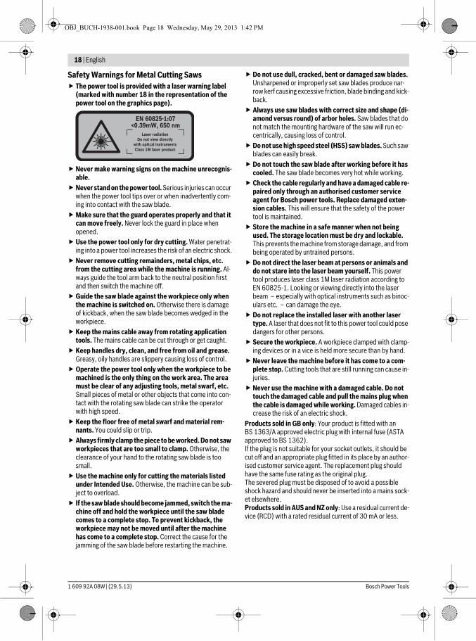
Safety Warnings for Metal Cutting Saws The power tool is provided with a laser warning label
(marked with number 18 in the representation of the power tool on the graphics page).
Never make warning signs on the machine unrecognis-able.
Never stand on the power tool. Serious injuries can occur when the power tool tips over or when inadvertently com-ing into contact with the saw blade.
Make sure that the guard operates properly and that it can move freely. Never lock the guard in place when opened.
Use the power tool only for dry cutting. Water penetrat-ing into a power tool increases the risk of an electric shock.
Never remove cutting remainders, metal chips, etc. from the cutting area while the machine is running. Al-ways guide the tool arm back to the neutral position first and then switch the machine off.
Guide the saw blade against the workpiece only when the machine is switched on. Otherwise there is damage of kickback, when the saw blade becomes wedged in the workpiece.
Keep the mains cable away from rotating application tools. The mains cable can be cut through or get caught.
Keep handles dry, clean, and free from oil and grease. Greasy, oily handles are slippery causing loss of control.
Operate the power tool only when the workpiece to be machined is the only thing on the work area. The area must be clear of any adjusting tools, metal swarf, etc. Small pieces of metal or other objects that come into con-tact with the rotating saw blade can strike the operator with high speed.
Keep the floor free of metal swarf and material rem-nants. You could slip or trip.
Always firmly clamp the piece to be worked. Do not saw workpieces that are too small to clamp. Otherwise, the clearance of your hand to the rotating saw blade is too small.
Use the machine only for cutting the materials listed under Intended Use. Otherwise, the machine can be sub-ject to overload.
If the saw blade should become jammed, switch the ma-chine off and hold the workpiece until the saw blade comes to a complete stop. To prevent kickback, the workpiece may not be moved until after the machine has come to a complete stop. Correct the cause for the jamming of the saw blade before restarting the machine.
Do not use dull, cracked, bent or damaged saw blades. Unsharpened or improperly set saw blades produce nar-row kerf causing excessive friction, blade binding and kick-back.
Always use saw blades with correct size and shape (di-amond versus round) of arbor holes. Saw blades that do not match the mounting hardware of the saw will run ec-centrically, causing loss of control.
Do not use high speed steel (HSS) saw blades. Such saw blades can easily break.
Do not touch the saw blade after working before it has cooled. The saw blade becomes very hot while working.
Check the cable regularly and have a damaged cable re-paired only through an authorised customer service agent for Bosch power tools. Replace damaged exten-sion cables. This will ensure that the safety of the power tool is maintained.
Store the machine in a safe manner when not being used. The storage location must be dry and lockable. This prevents the machine from storage damage, and from being operated by untrained persons.
Do not direct the laser beam at persons or animals and do not stare into the laser beam yourself. This power tool produces laser class 1M laser radiation according to EN 60825-1. Looking or viewing directly into the laser beam – especially with optical instruments such as binoc-ulars etc. – can damage the eye.
Do not replace the installed laser with another laser type. A laser that does not fit to this power tool could pose dangers for other persons.
Secure the workpiece. A workpiece clamped with clamp-ing devices or in a vice is held more secure than by hand.
Never leave the machine before it has come to a com-plete stop. Cutting tools that are still running can cause in-juries.
Never use the machine with a damaged cable. Do not touch the damaged cable and pull the mains plug when the cable is damaged while working. Damaged cables in-crease the risk of an electric shock.
Products sold in GB only: Your product is fitted with an BS 1363/A approved electric plug with internal fuse (ASTA approved to BS 1362).If the plug is not suitable for your socket outlets, it should be cut off and an appropriate plug fitted in its place by an author-ised customer service agent. The replacement plug should have the same fuse rating as the original plug.The severed plug must be disposed of to avoid a possible shock hazard and should never be inserted into a mains sock-et elsewhere.Products sold in AUS and NZ only: Use a residual current de-vice (RCD) with a rated residual current of 30 mA or less.
OBJ_BUCH-1938-001.book Page 18 Wednesday, May 29, 2013 1:42 PM
English | 19
Bosch Power Tools 1 609 92A 08W | (29.5.13)
SymbolsThe following symbols can be important for the operation of your power tool. Please memorise the symbols and their meanings. The correct interpretation of the symbols helps you operate the power tool better and more secure.
Product Description and Specifica-tions
Read all safety warnings and all instruc-tions. Failure to follow the warnings and in-structions may result in electric shock, fire and/or serious injury.
Intended UseThe machine is intended for stationary use with saw blades to perform lengthways and crossways straight cuts and miter angles to 45° in metal materials without the use of water.
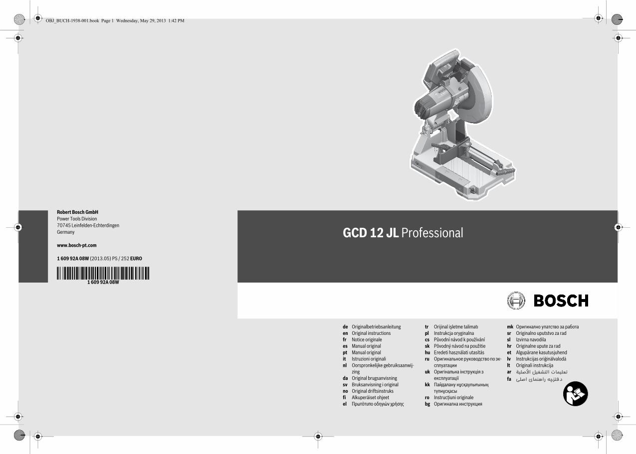
Product FeaturesThe numbering of the components shown refers to the repre-sentation of the power tool on the graphic pages.
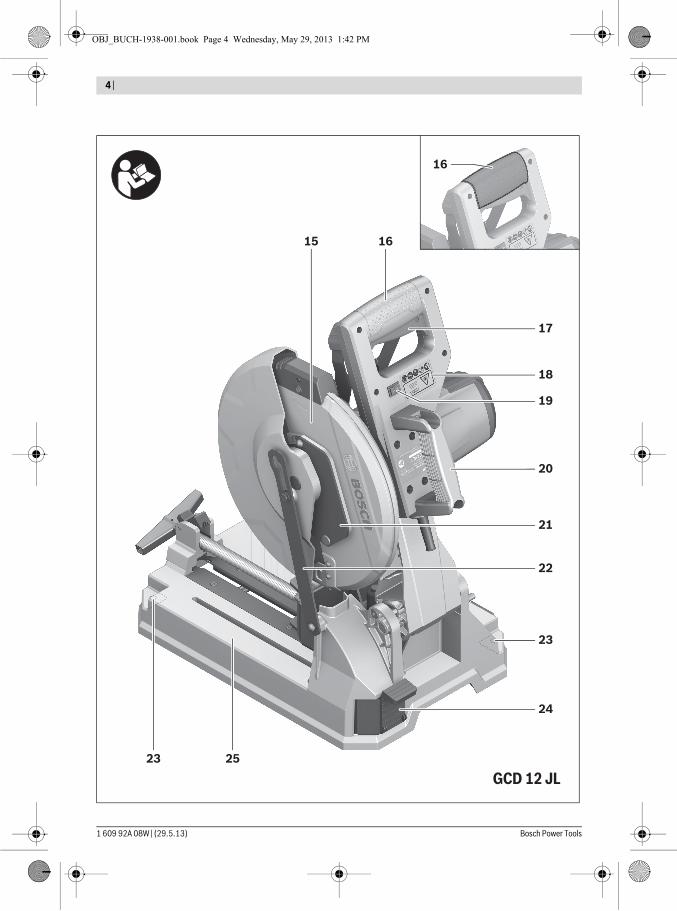
1 Locking lever2 Laser protection cap3 Spindle lock 4 Retracting blade guard5 Chip box6 Angle stop7 Clamping spindle8 Quick-release button9 Spindle handle
10 Clamping lever of the saw-table extension11 Saw-Table extension12 Allen key (size 6 mm)/Phillips screwdriver13 Tension handle to lock the angle stop14 Transport safety-lock15 Blade guard16 Handle17 On/Off switch18 Laser warning label19 Laser on/off switch (for marking of cutting line)20 Transport handle21 Cover plate22 Bracket23 Mounting holes24 Chip drawer25 Saw table26 Lower fastening screw
(cover plate/retracting blade guard)27 Upper fastening screw
(cover plate/retracting blade guard)28 Guide bolt29 Allen screw (size 6 mm) for mounting of saw blade 30 Clamping flange31 Saw blade32 Interior clamping flange 33 Angle display34 Scale for miter angles35 Adjustment screw for laser position
(parallelism)36 Screw for angle display
Accessories shown or described are not part of the standard deliv-ery scope of the product. A complete overview of accessories can be found in our accessories program.
Symbol Meaning Laser radiation
Do not view directly with optical in-strumentsClass 1M laser product
Keep hands away from the cutting ar-ea while the machine is running. Dan-ger of injury when coming in contact with the saw blade.
Wear ear protectors. Exposure to noise can cause hearing loss.
Wear safety goggles.
Wear a dust respirator.
Observe the dimensions of the saw blade. The hole diameter must match the tool spindle without play. Do not use reducers or adapters.
OBJ_BUCH-1938-001.book Page 19 Wednesday, May 29, 2013 1:42 PM
20 | English
1 609 92A 08W | (29.5.13) Bosch Power Tools
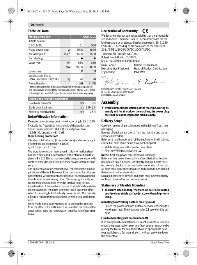
Technical Data
Noise/Vibration InformationMeasured sound values determined according to EN 61029.Typically the A-weighted noise levels of the product are: Sound pressure level 100 dB(A); Sound power level 113 dB(A). Uncertainty K =3 dB.Wear hearing protection!Vibration total values ah (triax vector sum) and uncertainty K determined according to EN 61029:ah =3.5 m/s2, K=1.5 m/s2.The vibration emission level given in this information sheet has been measured in accordance with a standardised test given in EN 61029 and may be used to compare one tool with another. It may be used for a preliminary assessment of expo-sure.The declared vibration emission level represents the main ap-plications of the tool. However if the tool is used for different applications, with different accessories or poorly maintained, the vibration emission may differ. This may significantly in-crease the exposure level over the total working period.An estimation of the level of exposure to vibration should also take into account the times when the tool is switched off or when it is running but not actually doing the job. This may sig-nificantly reduce the exposure level over the total working pe-riod.Identify additional safety measures to protect the operator from the effects of vibration such as: maintain the tool and the accessories, keep the hands warm, organisation of work pat-terns.
Declaration of ConformityWe declare under our sole responsibility that the product de-scribed under “Technical Data” is in conformity with the fol-lowing standards or standardization documents: EN 61029, EN 60825-1 according to the provisions of the directives 2011/65/EU, 2004/108/EC, 2006/42/EC.Technical file (2006/42/EC) at:Robert Bosch GmbH, PT/ETM9,D-70745 Leinfelden-Echterdingen
Robert Bosch GmbH, Power Tools Division D-70745 Leinfelden-Echterdingen Leinfelden, 29.05.2013
Assembly Avoid unintentional starting of the machine. During as-
sembly and for all work on the machine, the power plug must not be connected to the mains supply.
Delivery ScopeCarefully remove all parts included in the delivery from their packaging.Remove all packaging material from the machine and the ac-cessories provided.Before starting the operation of the machine for the first time, check if all parts listed below have been supplied:– Metal cutting saw with mounted saw blade– Allen key/Phillips screwdriver 12Note: Check the power tool for possible damage.Before further use of the machine, check that all protective devices are fully functional. Any lightly damaged parts must be carefully checked to ensure flawless operation of the tool. All parts must be properly mounted and all conditions fulfilled that ensure faultless operation.Damaged protective devices and parts must be immediately replaced by an authorised service centre.
Stationary or Flexible Mounting To ensure safe handling, the machine must be mounted
on a level and stable surface (e. g., workbench) prior to using.
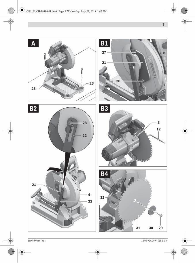
Mounting to a Working Surface (see figure A)– Fasten the power tool with suitable screw fasteners to the
working surface. The mounting holes 23 serve for this pur-pose.
Flexible Mounting (not recommended!)If, in exceptional circumstances, it is not possible to securely mount the power tool on a work surface, you can improvise by placing the feet of the saw-table 25 on an appropriate base (e.g. work bench, flat ground, etc.), without screwing down the power tool.
Metal Cutting Saw GCD 12 JLArticle number3 601 M28 ... ... 0.. ... 060Rated power input W 2000 1650No-load speed min-1 1500 1500Soft starting
Laser type nmmW
650< 0.39
650< 0.39
Laser class 1M 1MWeight according to EPTA-Procedure 01/2003 kg 20 20Protection class /II /IIPermissible workpiece dimensions (maximal/minimal) see page 22.The values given are valid for a nominal voltage [U] of 230 V. For differ-ent voltages and models for specific countries, these values can vary.
Dimension of suitable saw bladesSaw blade diameter mm 305Blade body thickness mm 1.8–2.5Mounting hole diameter mm 25.4
Henk BeckerExecutive Vice PresidentEngineering
Helmut HeinzelmannHead of Product CertificationPT/ETM9
OBJ_BUCH-1938-001.book Page 20 Wednesday, May 29, 2013 1:42 PM

English | 21
Bosch Power Tools 1 609 92A 08W | (29.5.13)
Changing the Saw Blade (see figures B1 –B4) Before any work on the machine itself, pull the mains
plug. Actuate the spindle lock 3 only when the tool spindle is
stopped. Otherwise, the machine can become damaged.When mounting the saw blade, wear protective gloves.
Danger of injury when touching the saw blade.Use only saw blades whose maximum permitted speed is higher than the no-load speed of the power tool.Use only saw blades that correspond with the characteristic data given in these operation instructions and that are tested and marked in accordance with EN 847-1.Use only saw blades recommended by the tool manufacturer, and suitable for sawing the materials to be cut.
Removing the Saw Blade– Bring the power tool into the working position. (see “Re-
leasing the Machine (Working Position)”, page 21)– Loosen the fastening screw 26 (approx. 2 turns) with the
Phillips screwdriver 12.Do not completely unscrew the screw.
– Loosen the fastening screw 27 (approx. 6 turns) with the Phillips screwdriver 12.Do not completely unscrew the screw.
– Push the locking lever 1 and swing the retracting blade guard 4 upwards to the stop.
– Then pull back the retracting guard blade 4 and the cover plate 21 from the fastening screw 27 until the retracting guard blade is held by the guide bolt 28 in the bracket 22.
– Turn the Allen screw 29 with the Allen key 12 provided while at the same time pressing the spindle lock 3 until it engages.
– Keep the spindle lock 3 pressed and unscrew the Allen screw 29 in anticlockwise direction.
– Remove the clamping flange 30.– Remove the saw blade 31.
Mounting the Saw BladeIf required, clean all parts to be mounted prior to assembly.– Place the new saw blade onto the interior clamping flange
32.When mounting the saw blade, pay attention that the
cutting direction of the teeth (arrow direction on the saw blade) corresponds with the direction of the arrow on the blade guard!
– Put on the clamping flange 30 and the screw 29.Press the spindle lock 3 until it engages and tighten the screw, turning in a clockwise direction.
– Loosen the spindle lock 3 again. If necessary, pull the knob by hand all the way up.
– Push the locking lever 1 and slide the retracting blade guard 4 and the cover plate 21 back under the fastening screw 27.
– Slowly guide the retracting guard blade 4 downwards until the saw blade is completely covered again.
– Retighten the fastening screws 27 and 26.
Operation Before any work on the machine itself, pull the mains
plug.
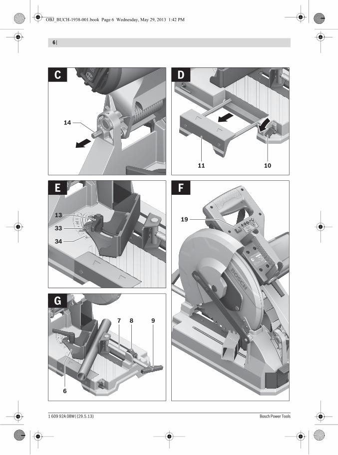
Transport Safety (see figure C)The transport safety-lock 14 enables easier handling of the machine when transporting to various working locations.
Releasing the Machine (Working Position)– Push the tool arm by the handle 16 down a little in order to
relieve the transport safety-lock 14.– Pull the transport safety-lock 14 completely outward.– Guide the tool arm slowly upward.Note: When working, pay attention that the transport safety-lock is not pushed inwards. Otherwise, the tool arm cannot be lowered to the requested depth.
Securing the Machine (Transport Position)– Guide the tool arm downward until the transport safety-
lock 14 can be pushed completely inward.For additional information on transport, see page 23.
Preparing for OperationExtending the Saw Table (see figure D)Long workpieces must be underlaid or supported at their free end.The saw-table can be extended leftward using the saw-table extension 11.– Fold the clamping lever 10 downwards.– Pull out the saw-table extension 11 to the desired length.– To lock the saw-table extension, pull the clamping lever 10
back up.
Adjusting the Cutting Angle (see figure E)The miter angle can be set in a range from 0° to 45°.Frequently used mitre angles are identified on the angle stop 6 with appropriate markings. The 0° and 45° position are set at the respective end stop.– Loosen the tension handle 13 of the angle stop 6.– Turn the angle stop 6 until the angle display 33 indicates
the desired miter angle on the scale 34.– Retighten the tension handle 13.
Marking the Cutting Line (see figure F)A laser beam indicates the cutting line of the saw blade. This allows for exact positioning of the workpiece for sawing, with-out having to open the retracting blade guard.– For this, switch the laser beam on with the switch 19.– Align the cutting mark on your workpiece with reference to
the right-hand edge of the laser line.Note: Before sawing, check if the cutting line is still indicated correctly (see “Adjusting the Laser”, page 23). The laser beam, as an example, can misadjust due to vibrations after in-tensive use.
OBJ_BUCH-1938-001.book Page 21 Wednesday, May 29, 2013 1:42 PM
22 | English
1 609 92A 08W | (29.5.13) Bosch Power Tools
Clamping the Workpiece (see figure G)To ensure optimum working safety, the workpiece must al-ways be firmly clamped.Do not saw workpieces that are too small to clamp.Long workpieces must be underlaid or supported at their free end.– Place the workpiece against the angle stop 6.– Slide the clamping spindle 7 against the workpiece and
firmly clamp the workpiece with the spindle handle 9.
Loosening the Workpiece– Loosen the spindle handle 9.– Tilt up the quick release 8 and pull the clamping spindle 7
away from the workpiece.
Working AdviceGeneral Sawing InstructionsProtect the saw blade against impact and shock. Do not sub-ject the saw blade to lateral pressure.Do not saw warped/bent workpieces. The workpiece must al-ways have a straight edge to face against the fence.Long workpieces must be underlaid or supported at their free end.
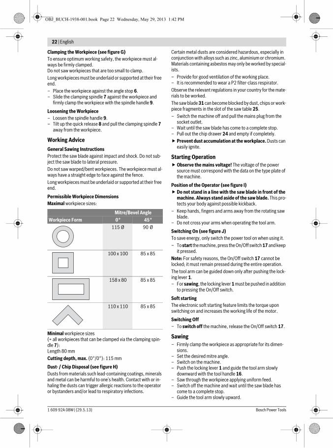
Permissible Workpiece DimensionsMaximal workpiece sizes:
Minimal workpiece sizes(= all workpieces that can be clamped via the clamping spin-dle 7):Length 80 mmCutting depth, max. (0°/0°): 115 mm
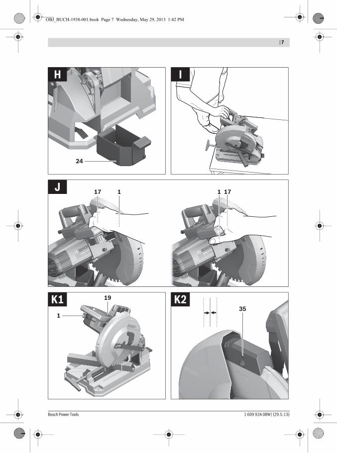
Dust- / Chip Disposal (see figure H)Dusts from materials such lead-containing coatings, minerals and metal can be harmful to one’s health. Contact with or in-haling the dusts can trigger allergic reactions to the operator or bystanders and/or lead to respiratory infections.
Certain metal dusts are considered hazardous, especially in conjunction with alloys such as zinc, aluminium or chromium. Materials containing asbestos may only be worked by special-ists.– Provide for good ventilation of the working place.– It is recommended to wear a P2 filter-class respirator.Observe the relevant regulations in your country for the mate-rials to be worked.The saw blade 31 can become blocked by dust, chips or work-piece fragments in the slot of the saw table 25.– Switch the machine off and pull the mains plug from the
socket outlet.– Wait until the saw blade has come to a complete stop.– Pull out the chip drawer 24 and empty if completely. Prevent dust accumulation at the workplace. Dusts can
easily ignite.
Starting Operation Observe the mains voltage! The voltage of the power
source must correspond with the data on the type plate of the machine.
Position of the Operator (see figure I) Do not stand in a line with the saw blade in front of the
machine. Always stand aside of the saw blade. This pro-tects your body against possible kickback.
– Keep hands, fingers and arms away from the rotating saw blade.
– Do not cross your arms when operating the tool arm.
Switching On (see figure J)To save energy, only switch the power tool on when using it.– To start the machine, press the On/Off switch 17 and keep
it pressed.Note: For safety reasons, the On/Off switch 17 cannot be locked; it must remain pressed during the entire operation.The tool arm can be guided down only after pushing the lock-ing lever 1.– For sawing, the locking lever 1 must be pushed in addition
to pressing the On/Off switch.
Soft startingThe electronic soft starting feature limits the torque upon switching on and increases the working life of the motor.
Switching Off– To switch off the machine, release the On/Off switch 17.
Sawing– Firmly clamp the workpiece as appropriate for its dimen-
sions.– Set the desired mitre angle.– Switch on the machine.– Push the locking lever 1 and guide the tool arm slowly
downward with the tool handle 16.– Saw through the workpiece applying uniform feed.– Switch off the machine and wait until the saw blade has
come to a complete stop.– Guide the tool arm slowly upward.
Mitre/Bevel AngleWorkpiece Form 0° 45°
115 Ø 90 Ø
100 x 100 85 x 85
158 x 80 85 x 85
110 x 110 85 x 85
OBJ_BUCH-1938-001.book Page 22 Wednesday, May 29, 2013 1:42 PM
English | 23
Bosch Power Tools 1 609 92A 08W | (29.5.13)
Checking and Adjusting the Basic Adjustment Before any work on the machine itself, pull the mains
plug.To ensure precise cuts, the basic adjustment of the machine must be checked and adjusted as necessary after intensive use.A certain level of experience and appropriate specialty tools are required for this.A Bosch after-sales service station will handle this mainte-nance task quickly and reliably.
Adjusting the LaserNote: To test the laser function, the machine must be con-nected to power.While adjusting the laser (e. g. when moving the tool
arm), never actuate the On/Off switch. Accidental start-ing of the power tool can lead to injuries.
– Bring the power tool into the working position.Checking: (see figure K1)– Draw a straight cutting line on the workpiece.– Push the locking lever 1 and guide the tool arm slowly
downward with the tool handle 16.– Align the workpiece in such a manner that the teeth of the
saw blade are in alignment with the cutting line.– Hold the workpiece in this position and slowly guide the
tool arm upward again.– Clamp the workpiece.– Switch the laser beam on with switch 19.The laser beam must be in alignment with the cutting line on the workpiece over the complete length, also when the tool arm is lowered.Adjusting: (see figure K2)– Turn the adjustment screw 35 with the Phillips screwdriv-
er 12 provided until the laser beam is parallel to the com-plete length of the cutting line on the workpiece.
One rotation in anticlockwise direction moves the laser beam from left to right; one rotation in clockwise direction moves the laser beam from right to left.
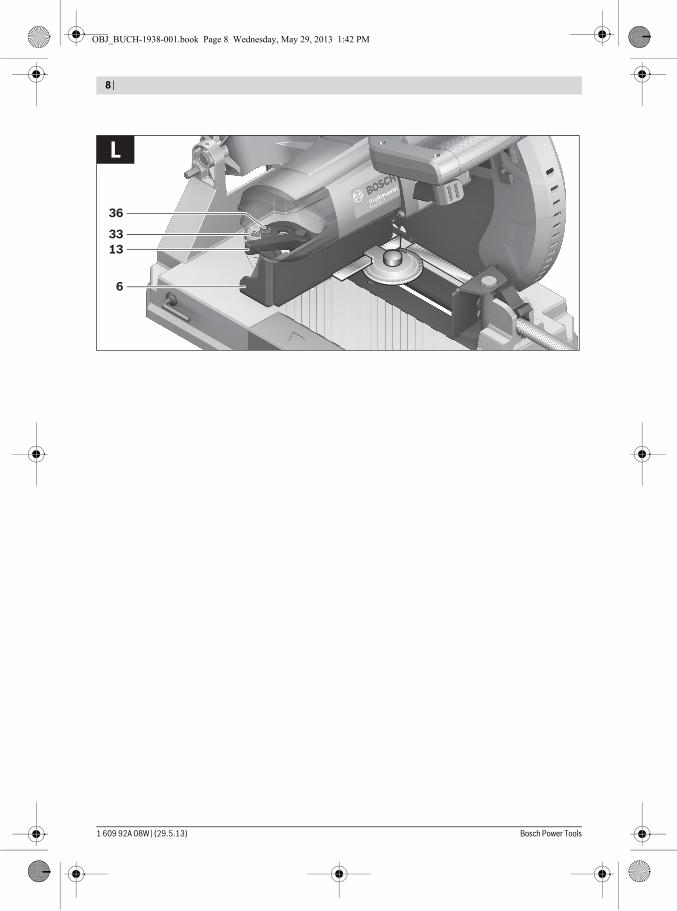
Aligning the Angle Display (see figure L)– Bring the machine into the transport position.– Loosen the tension handle 13 of the angle stop 6.– Turn the angle stop 6 until the stop to the 0° position.Checking:– Adjust an angle gauge to 90° and position it between the
angle stop 6 and the saw blade 31 on the saw-table 25.The leg of the angle gauge must be flush with the angle stop over the complete length.Adjusting:– Twist the angle stop 6 until the leg of the angle gauge is
flush with the saw blade over the complete length.– Retighten the tension handle 13.– Loosen the screw 36 with the Phillips screwdriver 12 pro-
vided and align the angle indicator along the 0° mark.– Retighten the screw again.
TransportBefore transporting the power tool, the following steps must be carried out:– Bring the machine into the transport position.– Remove all accessories that cannot be mounted firmly to
the power tool.If possible, place unused saw blades in an enclosed con-tainer for transport.
– Always carry the power tool by its transport handle 20. The power tool should always be carried by two per-
sons in order to avoid back injuries.When transporting the power tool, use only the trans-
port devices and never use the protective devices.
Maintenance and ServiceMaintenance and Cleaning Before any work on the machine itself, pull the mains
plug. Clean the ventilation slots of your power tool regularly
with a soft brush. The motor fan draws dust into the hous-ing, and a large accumulation of metal dust can lead to electrical hazards.
In extreme conditions, always use dust extraction as far as possible. Blow out ventilation slots frequently and install a residual current device (RCD). When work-ing metals, conductive dust can settle in the interior of the power tool. The total insulation of the power tool can be im-paired.
Have maintenance and repair work performed only by qualified specialists. In this manner, it can be ensured that the safety of the power tool is maintained.
The retracting blade guard must always be able to move freely and retract automatically. Therefore, always keep the area around the retracting blade guard clean.If the replacement of the supply cord is necessary, this has to be done by Bosch or an authorized Bosch service agent in or-der to avoid a safety hazard.
Accessories
After-sales Service and Application ServiceIn all correspondence and spare parts order, please always in-clude the 10-digit article number given on the type plate of the machine.Our after-sales service responds to your questions concern-ing maintenance and repair of your product as well as spare parts. Exploded views and information on spare parts can al-so be found under:www.bosch-pt.comBosch’s application service team will gladly answer questions concerning our products and their accessories.
Article numberSaw blade 305 x 25.4 mm, 60 teeth 2 608 643 060Saw blade 305 x 25.4 mm, 80 teeth 2 608 643 061
OBJ_BUCH-1938-001.book Page 23 Wednesday, May 29, 2013 1:42 PM


![WBTS: the new class of WSTS without WQOfinkel/2016-2017/slides-WBTS-workshop-etaps-2017.pdf · on the Grand Central Dispatch (GCD) technology [13] , and to perform parametric verication](https://static.fdocument.org/doc/165x107/6055249bdb755b39f964022f/wbts-the-new-class-of-wsts-without-finkel2016-2017slides-wbts-workshop-etaps-2017pdf.jpg)