Gaseous Tracker R&D
26
Gaseous Tracker R&D ILC Detector Test Beam Workshop Fermi National Accelerator Laboratory January 17-19, 2007 17 Madhu Dixit Carleton University & TRIUMF
Transcript of Gaseous Tracker R&D
Gaseous Tracker R&D
ILC Detector Test Beam WorkshopFermi National Accelerator Laboratory
January 17-19, 200717
Madhu DixitCarleton University & TRIUMF
Fermilab 1/18/2007 M. Dixit 2
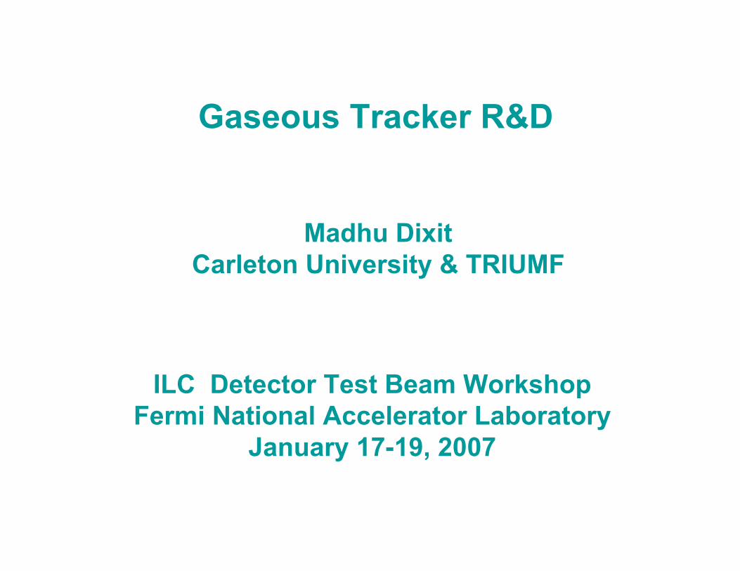
ILC Physics Motivation• Critical to fully understanding LHC physics results.• Model independent Higgs
measurements including invisible decays of the Higgs:
e+ e- -> Z° H° or Z° Z°Measure recoil mass against Z° -> l+ l−
• Precision measurements – ∆MTop≈ 100 MeV, ∆ΓTop ≈ 2%– ∆MZ & ∆MW ≈ 5 MeV (from 30 MeV)– ∆(sin2ϑ) ≈ 10-5 (from 2·10-4)
• Cover any LHC blindspots
Fermilab 1/18/2007 M. Dixit 3
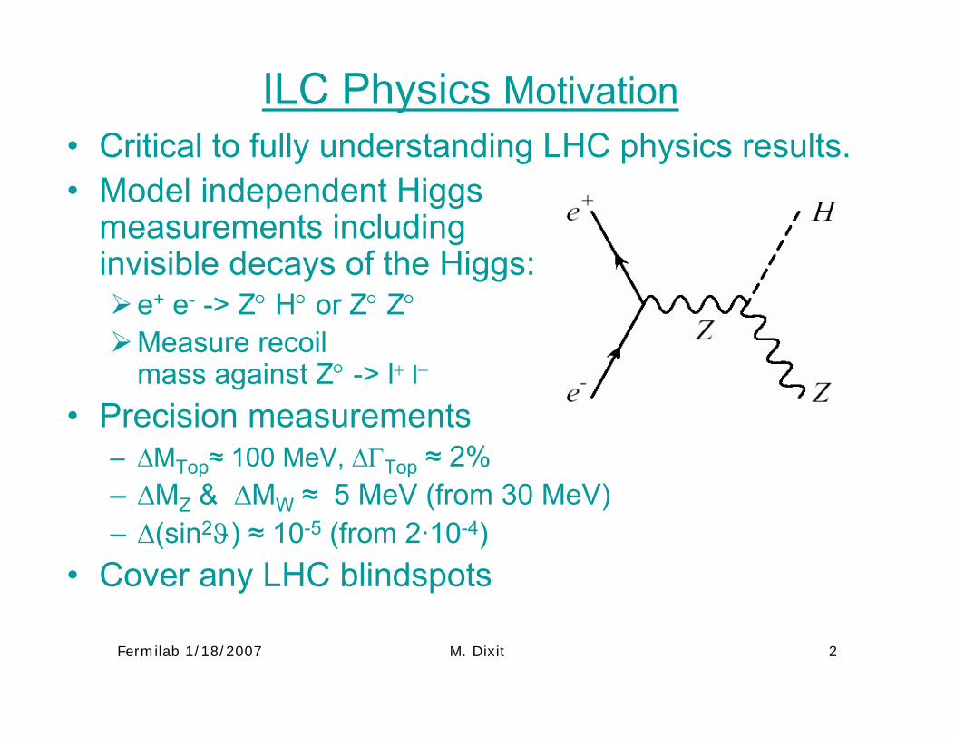
ILC tracker resolution driverMeasure Higgs recoil mass accuracy limited by beam energy spread.
∆(1/pT) ~ 3 x10⁻⁵ (GeV/c)-1 (more than 10 times better than at LEP!)
MH = 120 GeV/c2
Fermilab 1/18/2007 M. Dixit 4
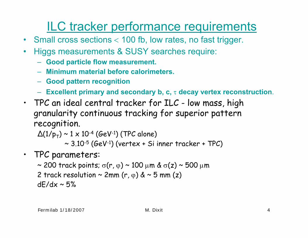
ILC tracker performance requirements• Small cross sections < 100 fb, low rates, no fast trigger.• Higgs measurements & SUSY searches require:
– Good particle flow measurement. – Minimum material before calorimeters.– Good pattern recognition– Excellent primary and secondary b, c, τ decay vertex reconstruction.
• TPC an ideal central tracker for ILC - low mass, high granularity continuous tracking for superior pattern recognition.∆(1/pT) ~ 1 x 10⁻⁴ (GeV-1) (TPC alone)
~ 3.10-5 (GeV-1) (vertex + Si inner tracker + TPC)• TPC parameters:
~ 200 track points; σ(r, ϕ) ~ 100 µm & σ(z) ~ 500 µm 2 track resolution ~ 2mm (r, ϕ) & ~ 5 mm (z) dE/dx ~ 5%
Fermilab 1/18/2007 M. Dixit 5
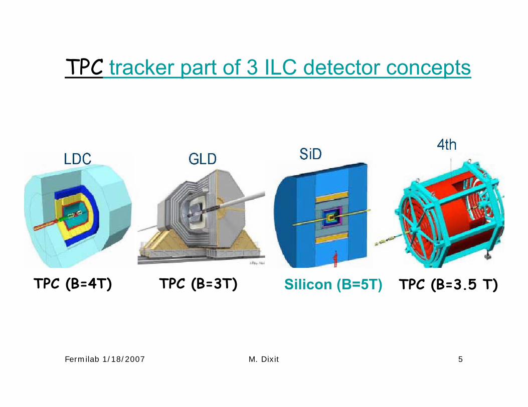
TPC tracker part of 3 ILC detector concepts
Silicon (B=5T)TPC (B=4T) TPC (B=3T) TPC (B=3.5 T)
Fermilab 1/18/2007 M. Dixit 6
cm
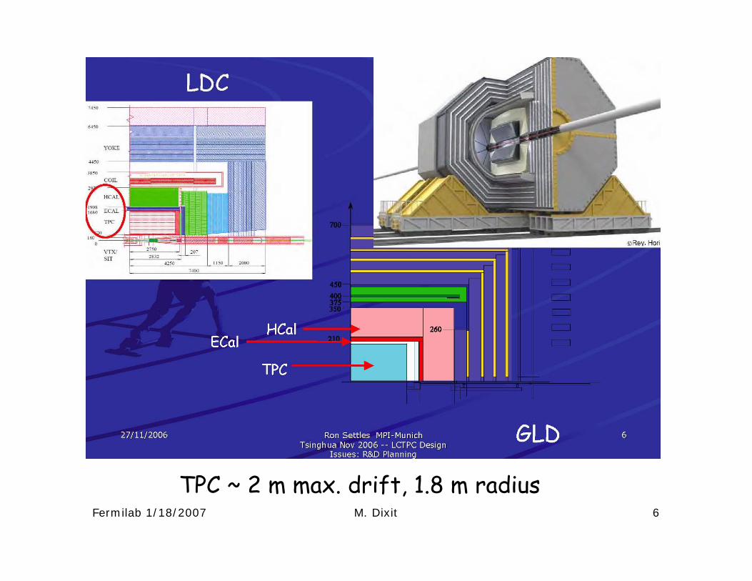
TPC ~ 2 m max. drift, 1.8 m radius
Fermilab 1/18/2007 M. Dixit 7
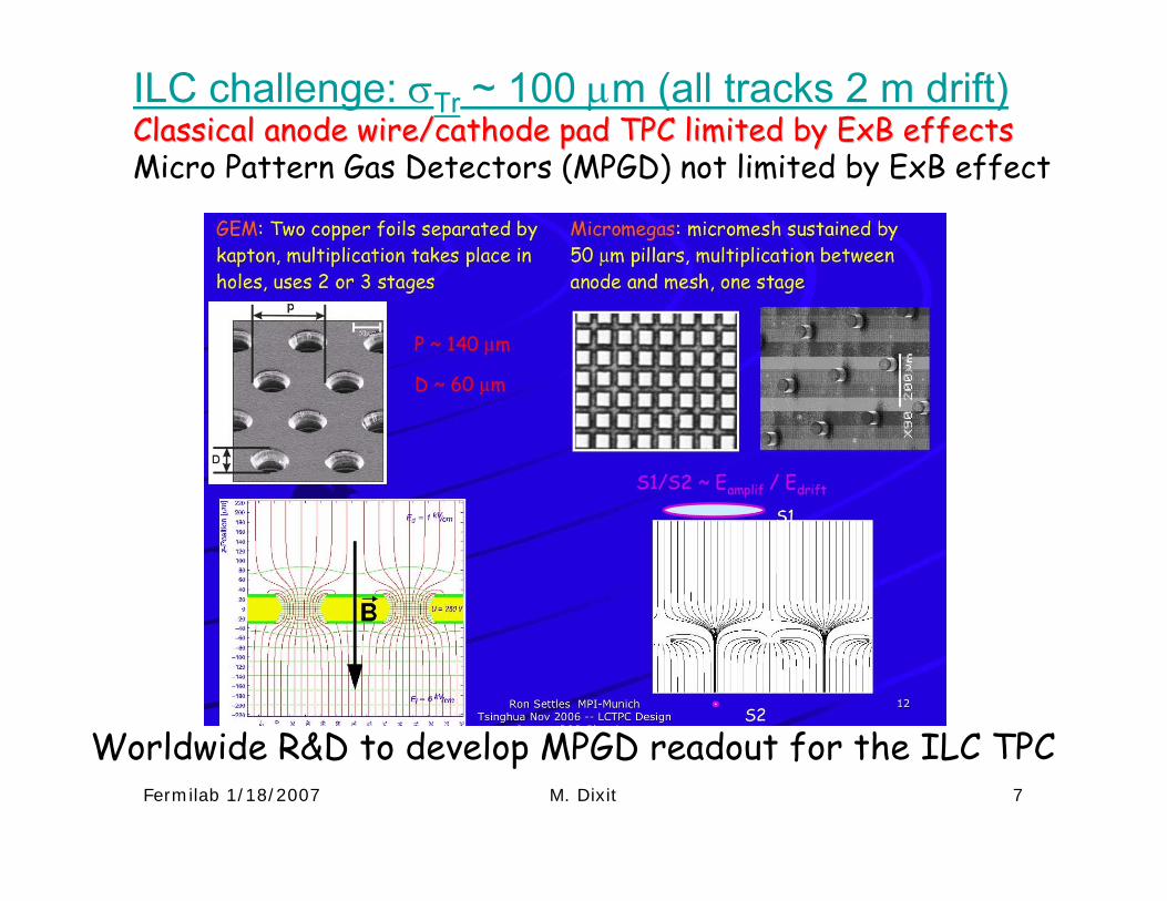
ILC challenge: σTr ~ 100 µm (all tracks 2 m drift) Classical anode wire/cathode pad TPC limited by Classical anode wire/cathode pad TPC limited by ExBExB effectseffectsMicro Pattern Gas Detectors (MPGD) not limited by ExB effect
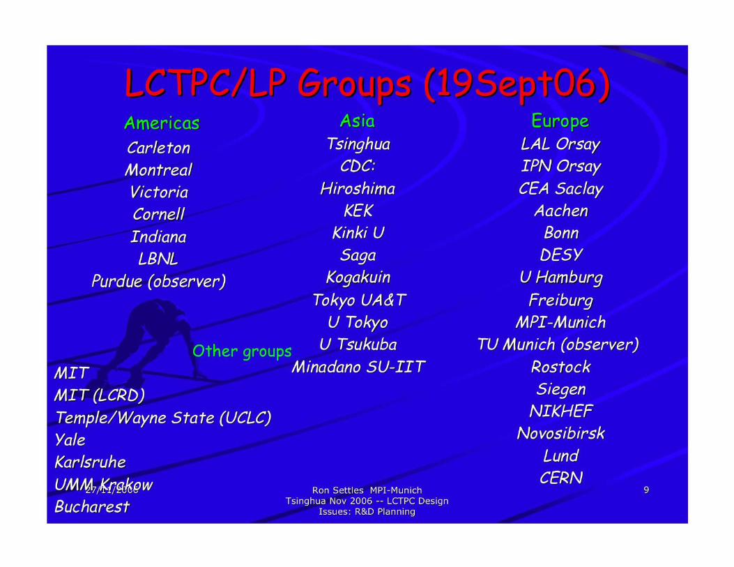
Worldwide R&D to develop MPGD readout for the ILC TPC
Fermilab 1/18/2007 M. Dixit 8
Fermilab 1/18/2007 M. Dixit 9
Fermilab 1/18/2007 M. Dixit 10
Fermilab 1/18/2007 M. Dixit 11
Fermilab 1/18/2007 M. Dixit 12
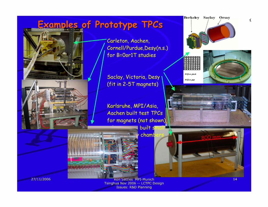
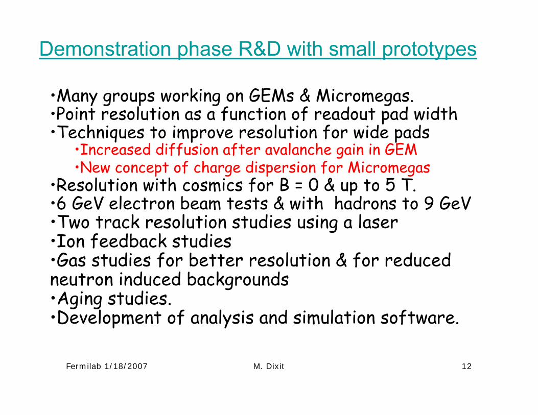
Demonstration phase R&D with small prototypes
•Many groups working on GEMs & Micromegas.•Point resolution as a function of readout pad width•Techniques to improve resolution for wide pads
•Increased diffusion after avalanche gain in GEM•New concept of charge dispersion for Micromegas
•Resolution with cosmics for B = 0 & up to 5 T.•6 GeV electron beam tests & with hadrons to 9 GeV•Two track resolution studies using a laser•Ion feedback studies•Gas studies for better resolution & for reduced neutron induced backgrounds•Aging studies.•Development of analysis and simulation software.
Fermilab 1/18/2007 M. Dixit 13
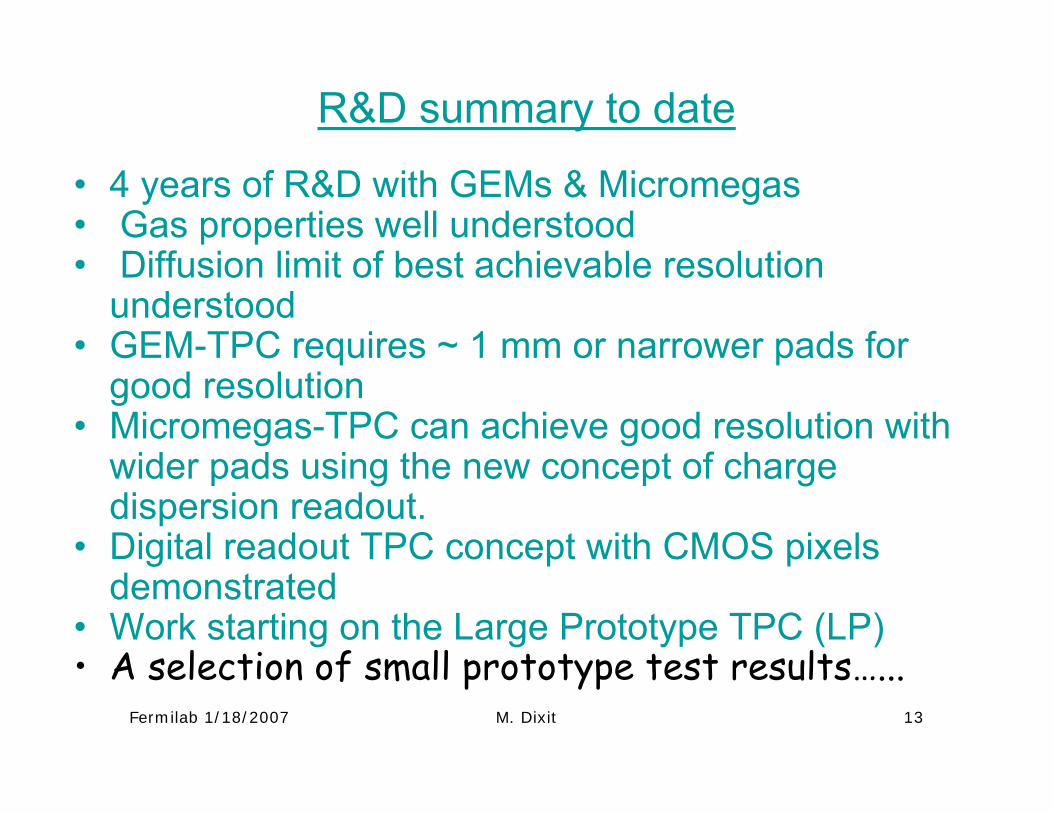
R&D summary to date
• 4 years of R&D with GEMs & Micromegas• Gas properties well understood• Diffusion limit of best achievable resolution
understood• GEM-TPC requires ~ 1 mm or narrower pads for
good resolution • Micromegas-TPC can achieve good resolution with
wider pads using the new concept of charge dispersion readout.
• Digital readout TPC concept with CMOS pixels demonstrated
• Work starting on the Large Prototype TPC (LP)• A selection of small prototype test results…...
Fermilab 1/18/2007 M. Dixit 14
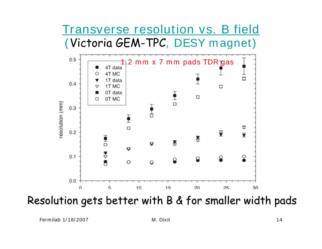
Transverse resolution vs. B field (Victoria GEM-TPC, DESY magnet)
1.2 mm x 7 mm pads TDR gas
Resolution gets better with B & for smaller width padsResolution gets better with B & for smaller width pads
Fermilab 1/18/2007 M. Dixit 15
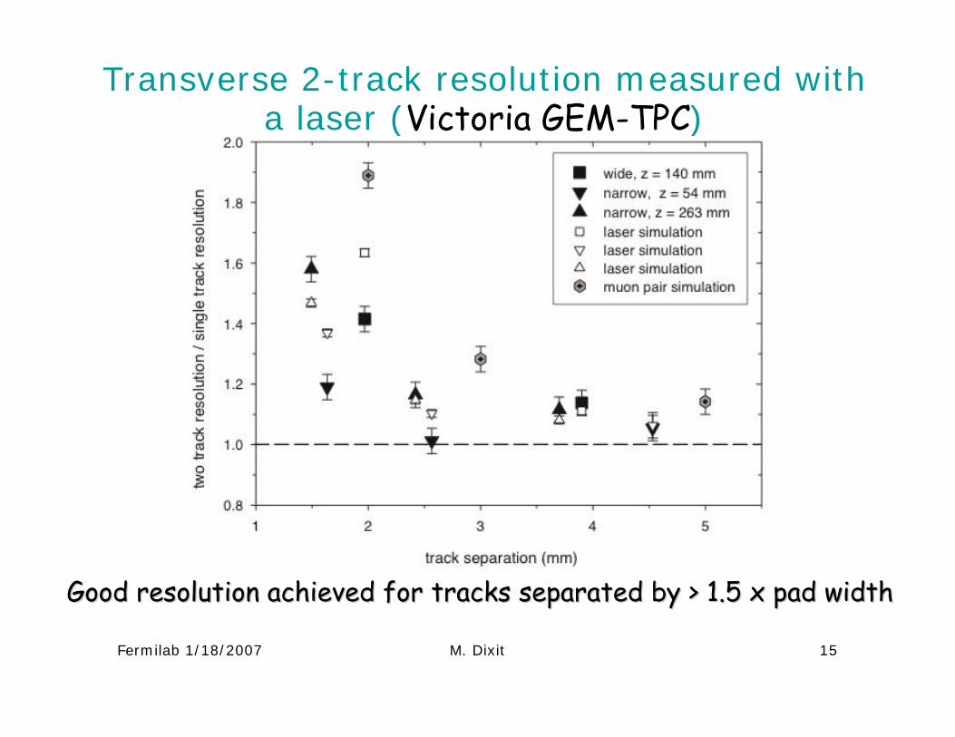
Transverse 2-track resolution measured with a laser (Victoria GEM-TPC)
Good resolution achieved for tracks separated by > 1.5 x pad widGood resolution achieved for tracks separated by > 1.5 x pad widthth
Fermilab 1/18/2007 M. Dixit 16
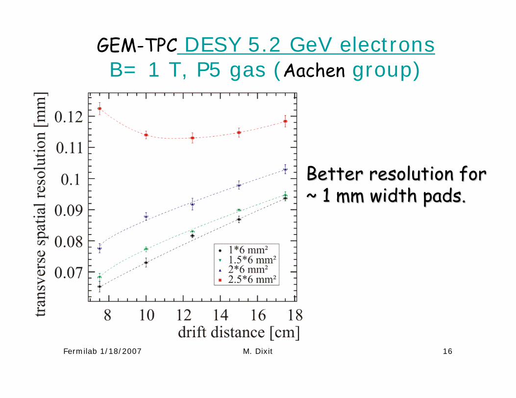
GEM-TPC DESY 5.2 GeV electronsB= 1 T, P5 gas (Aachen group)
Better resolution for Better resolution for ~ 1 mm width pads.~ 1 mm width pads.
Fermilab 1/18/2007 M. Dixit 17
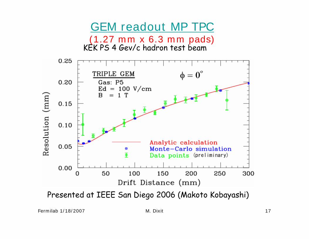
GEM readout MP TPC (1.27 mm x 6.3 mm pads)
KEK PS 4 Gev/c hadron test beam
Presented at IEEE San Diego 2006 (Makoto Kobayashi)
Fermilab 1/18/2007 M. Dixit 18
Global Likelihood
Chi2
drift distance (mm)re
solu
tion
(mm
)
ArIso(95:5), B=1T
MP-TPC Micromegas
Analytical Theory Neff=18.5 c)
0
0.1
0.2
0.3
0.4
0.5
0.6
0.7
0.8
0 100 200
Global Likelihood
Chi2
drift distance (mm)
reso
lutio
n (m
m)
ArIso(95:5), B=0.5T
MP-TPC Micromegas
Analytical Theory Neff=18.5 b)
0
0.1
0.2
0.3
0.4
0.5
0.6
0.7
0.8
0 100 200
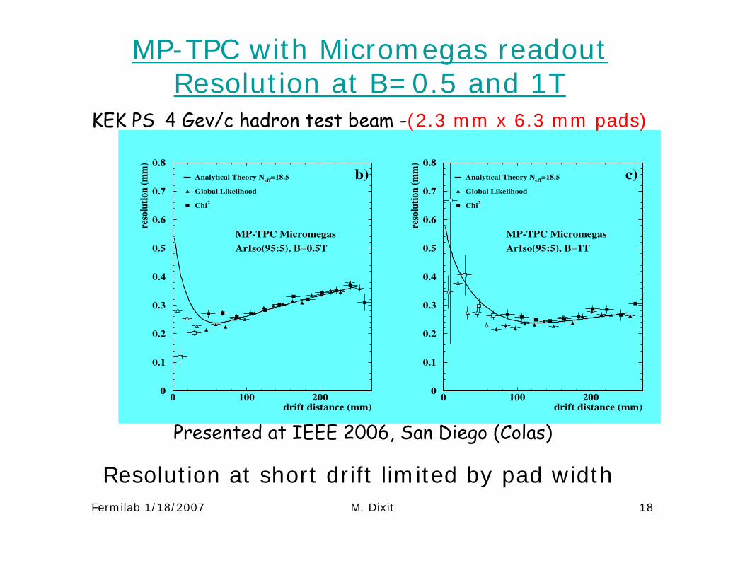
MP-TPC with Micromegas readoutResolution at B=0.5 and 1T
KEK PS 4 Gev/c hadron test beam -(2.3 mm x 6.3 mm pads)
Presented at IEEE 2006, San Diego (Colas)
Resolution at short drift limited by pad width
Fermilab 1/18/2007 M. Dixit 19
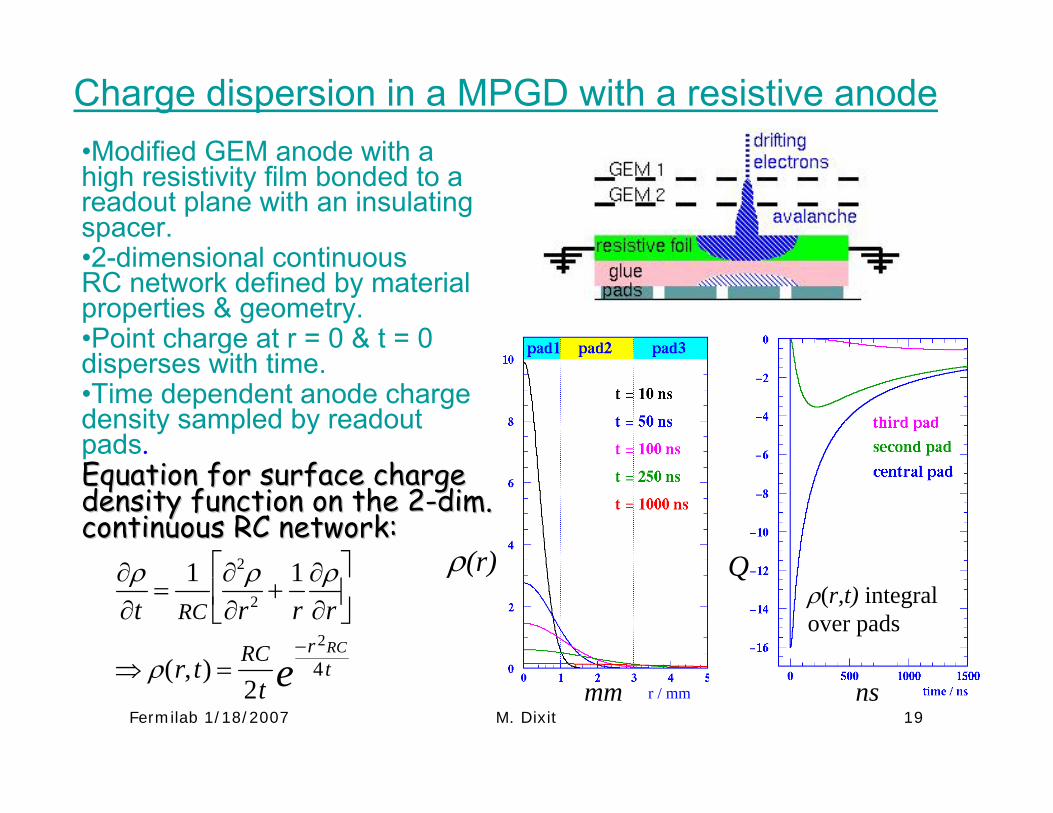
•Modified GEM anode with a high resistivity film bonded to a readout plane with an insulating spacer.•2-dimensional continuous RC network defined by material properties & geometry.•Point charge at r = 0 & t = 0 disperses with time.•Time dependent anode charge density sampled by readout pads.Equation for surface charge Equation for surface charge density function on the 2density function on the 2--dim. dim. continuous RC network:continuous RC network:
∂ρ∂t
=1
RC
∂2ρ∂r2 +
1r
∂ρ∂r
⎡
⎣ ⎢
⎤
⎦ ⎥
⇒ ρ(r, t) =RC
2t
−r 2RC4 te
ρ(r,t) integral over pads
ρ(r) Q
r / mmmm ns
Charge dispersion in a MPGD with a resistive anode
Fermilab 1/18/2007 M. Dixit 20
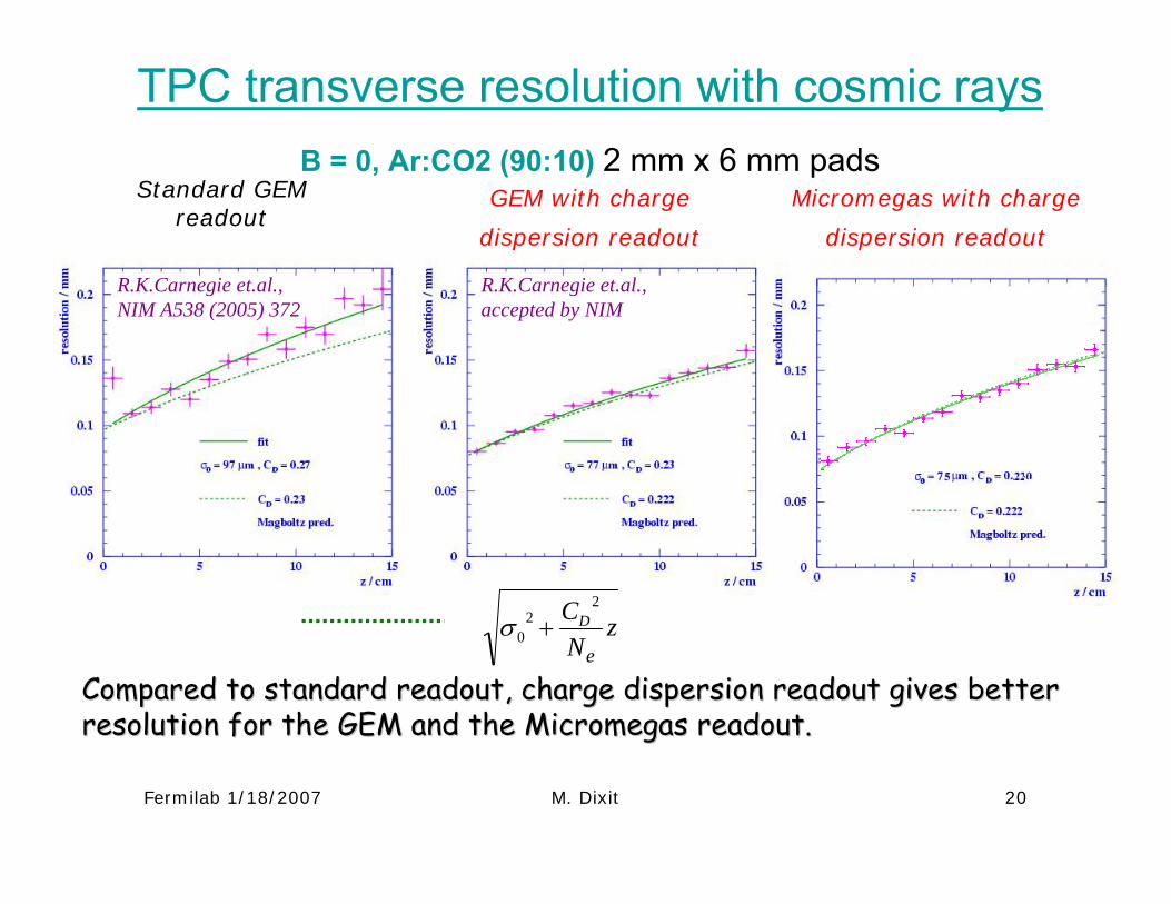
Standard GEM readout
GEM with charge
dispersion readout
Compared to standard readout, charge dispersion readout gives beCompared to standard readout, charge dispersion readout gives better tter resolution for the GEM and the Micromegas readout. resolution for the GEM and the Micromegas readout.
Micromegas with charge
dispersion readout
TPC transverse resolution with cosmic rays B = 0, Ar:CO2 (90:10) 2 mm x 6 mm pads
R.K.Carnegie et.al., NIM A538 (2005) 372
R.K.Carnegie et.al., accepted by NIM
σ 02 +
CD2
Nez
Measurements affected by gas leak discovered laterFirst results
Fermilab 1/18/2007 M. Dixit 21
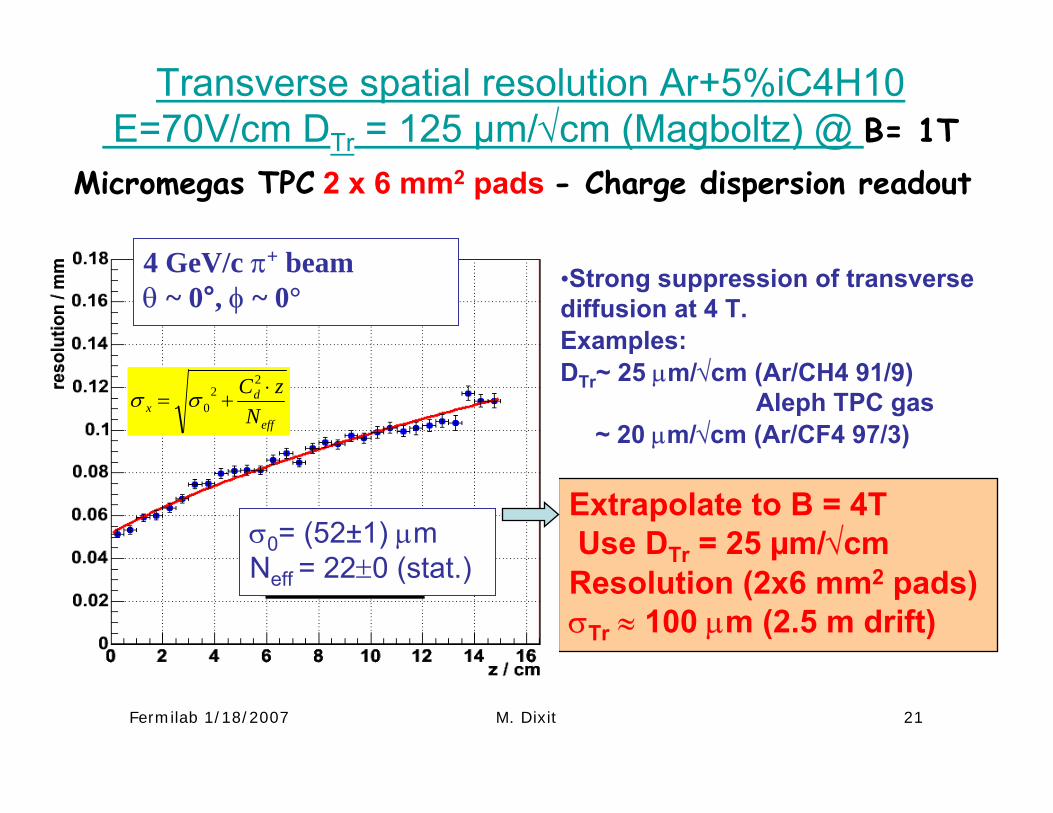
Extrapolate to B = 4TUse DTr = 25 µm/√cm Resolution (2x6 mm2 pads) σTr ≈ 100 µm (2.5 m drift)
Transverse spatial resolution Ar+5%iC4H10 E=70V/cm DTr = 125 µm/√cm (Magboltz) @ B= 1T
σ x = σ 02 +
Cd2 ⋅ z
Neff
4 GeV/c π+ beamθ ~ 0°, φ ~ 0°
σ0= (52±1) µm Neff = 22±0 (stat.)
Micromegas TPC 2 x 6 mm2 pads - Charge dispersion readout
•Strong suppression of transverse diffusion at 4 T.Examples:DTr~ 25 µm/√cm (Ar/CH4 91/9)
Aleph TPC gas ~ 20 µm/√cm (Ar/CF4 97/3)
Fermilab 1/18/2007 M. Dixit 22
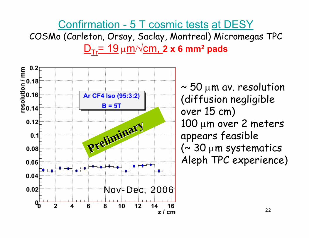
Confirmation - 5 T cosmic tests at DESY COSMo (Carleton, Orsay, Saclay, Montreal) Micromegas TPC
DTr= 19 µm/√cm, 2 x 6 mm2 pads
~ 50 µm av. resolution (diffusion negligible over 15 cm)100 µm over 2 meters appears feasible (~ 30 µm systematicsAleph TPC experience)
Preliminary
Preliminary
Nov-Dec, 2006
Fermilab 1/18/2007 M. Dixit 23
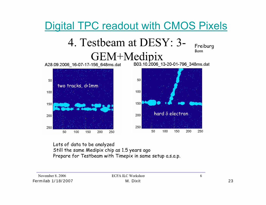
Digital TPC readout with CMOS Pixels
Fermilab 1/18/2007 M. Dixit 24
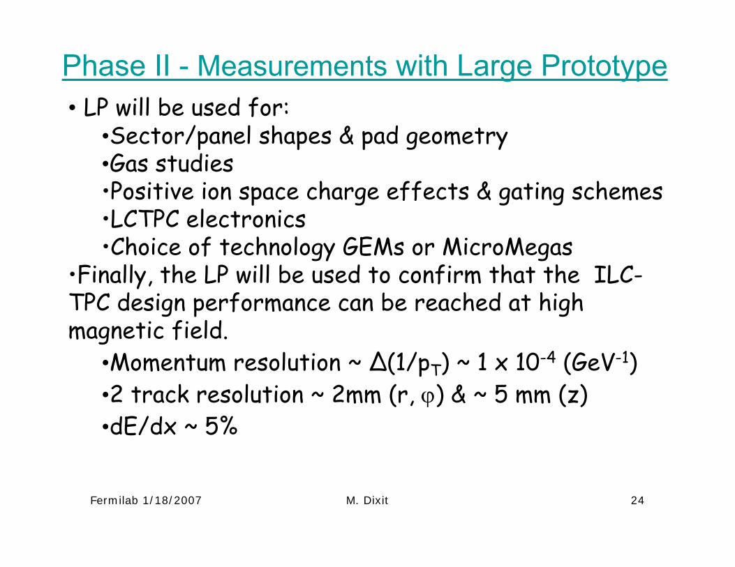
Phase II - Measurements with Large Prototype• LP will be used for:
•Sector/panel shapes & pad geometry•Gas studies•Positive ion space charge effects & gating schemes •LCTPC electronics •Choice of technology GEMs or MicroMegas
•Finally, the LP will be used to confirm that the ILC-TPC design performance can be reached at high magnetic field.
•Momentum resolution ~ ∆(1/pT) ~ 1 x 10⁻⁴ (GeV-1)•2 track resolution ~ 2mm (r, ϕ) & ~ 5 mm (z) •dE/dx ~ 5%
Fermilab 1/18/2007 M. Dixit 25
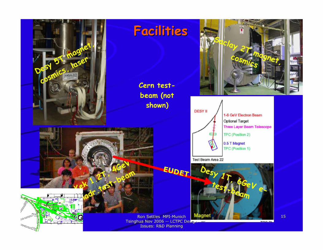
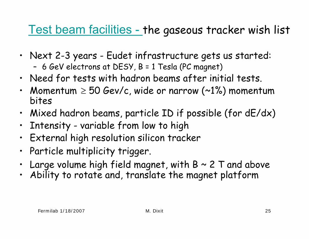
Test beam facilities - the gaseous tracker wish list
• Next 2-3 years - Eudet infrastructure gets us started:– 6 GeV electrons at DESY, B = 1 Tesla (PC magnet)
• Need for tests with hadron beams after initial tests.• Momentum ≥ 50 Gev/c, wide or narrow (~1%) momentum
bites • Mixed hadron beams, particle ID if possible (for dE/dx)• Intensity - variable from low to high • External high resolution silicon tracker• Particle multiplicity trigger.• Large volume high field magnet, with B ~ 2 T and above• Ability to rotate and, translate the magnet platform
Fermilab 1/18/2007 M. Dixit 26
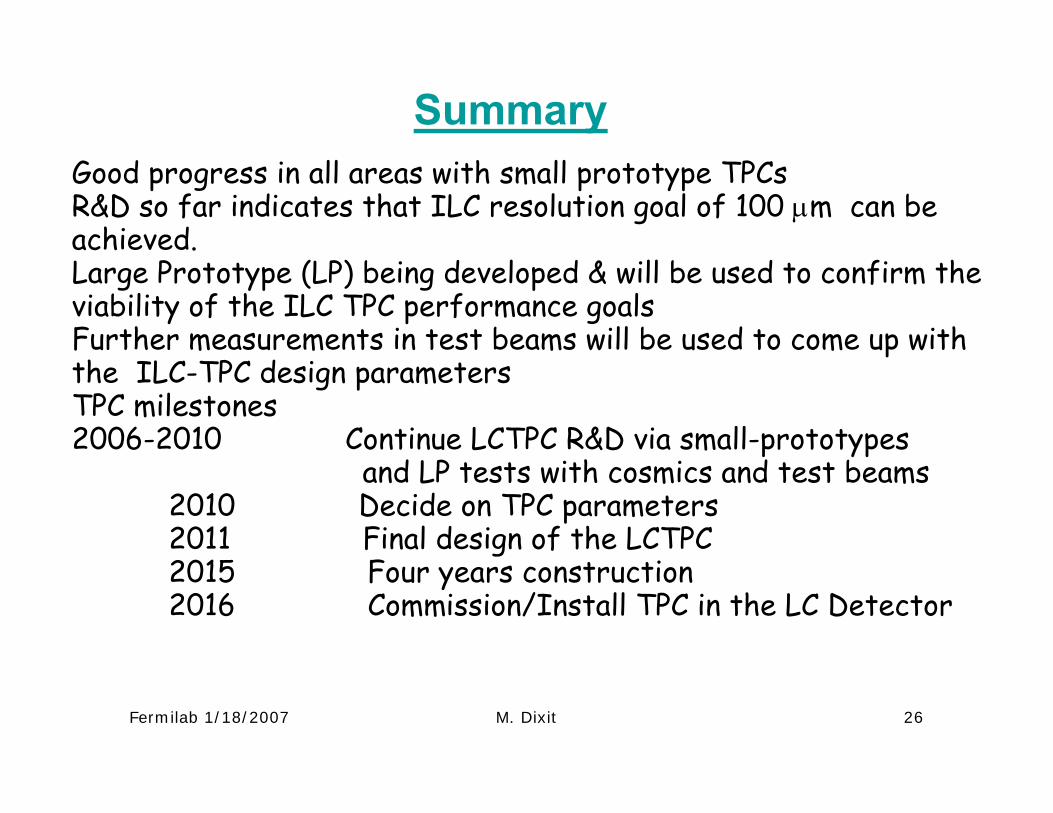
SummaryGood progress in all areas with small prototype TPCsR&D so far indicates that ILC resolution goal of 100 µm can be achieved.Large Prototype (LP) being developed & will be used to confirm the viability of the ILC TPC performance goalsFurther measurements in test beams will be used to come up with the ILC-TPC design parametersTPC milestones2006-2010 Continue LCTPC R&D via small-prototypes
and LP tests with cosmics and test beams2010 Decide on TPC parameters2011 Final design of the LCTPC2015 Four years construction2016 Commission/Install TPC in the LC Detector