Gaseous detectors - DESY · Influences the timing behavior of gas detectors ... Avalanche process...
39
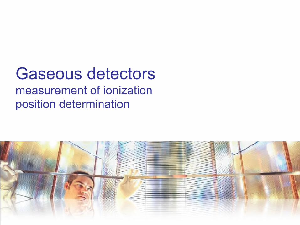
1 Gaseous detectors measurement of ionization position determination
Transcript of Gaseous detectors - DESY · Influences the timing behavior of gas detectors ... Avalanche process...
1
Gaseous detectors measurement of ionization position determination
2
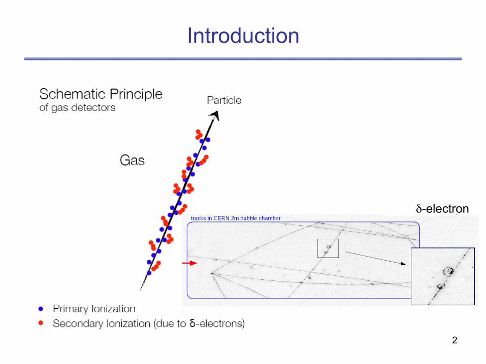
Introduction
δ-electron
3
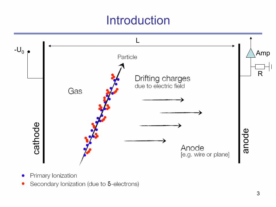
Introduction
-U0
cath
ode
anod
e
Amp
R
L
4
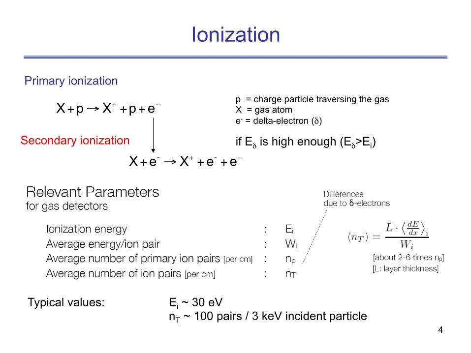
Ionization
−+ ++→+ epXpXp = charge particle traversing the gas X = gas atom e- = delta-electron (δ)
Primary ionization
−+ ++→+ eeXeX --
Secondary ionization if Eδ is high enough (Eδ>Ei)
Typical values: Ei ~ 30 eV nT ~ 100 pairs / 3 keV incident particle
5
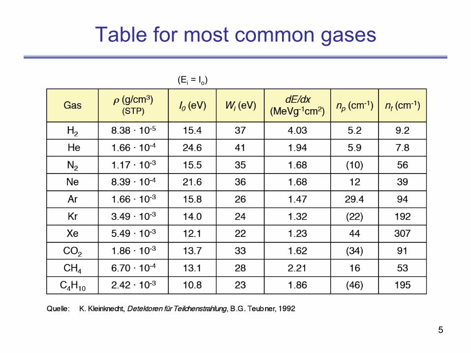
Table for most common gases
(Ei = Io)
6
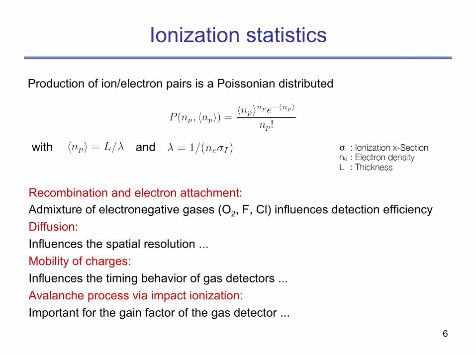
Ionization statistics
Recombination and electron attachment: Admixture of electronegative gases (O2, F, Cl) influences detection efficiency Diffusion: Influences the spatial resolution ... Mobility of charges: Influences the timing behavior of gas detectors ... Avalanche process via impact ionization: Important for the gain factor of the gas detector ...
Production of ion/electron pairs is a Poissonian distributed
with and
7
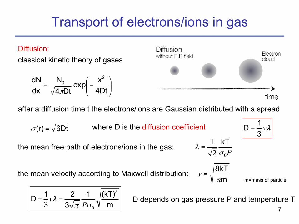
Transport of electrons/ions in gas
Diffusion: classical kinetic theory of gases
⎟⎟⎠
⎞⎜⎜⎝
⎛−=4Dtxexp
Dt4N
dxdN 2
0
π
after a diffusion time t the electrons/ions are Gaussian distributed with a spread
6Dt(r) =σ where D is the diffusion coefficient λv31D =
the mean free path of electrons/ions in the gas: the mean velocity according to Maxwell distribution:
D = 13vλ = 2
3 π1Pσ 0
(kT)3
m
m8kTπ
=v
λ =12kTσ 0P
m=mass of particle
D depends on gas pressure P and temperature T
8
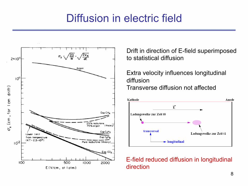
Diffusion in electric field
Drift in direction of E-field superimposed to statistical diffusion Extra velocity influences longitudinal diffusion Transverse diffusion not affected
E-field reduced diffusion in longitudinal direction
9
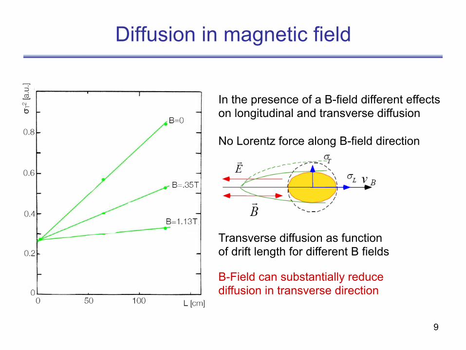
Diffusion in magnetic field
In the presence of a B-field different effects on longitudinal and transverse diffusion No Lorentz force along B-field direction
B-Field can substantially reduce diffusion in transverse direction
Transverse diffusion as function of drift length for different B fields
10
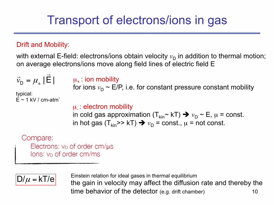
Transport of electrons/ions in gas
Drift and Mobility:
|E|D
±= µv
with external E-field: electrons/ions obtain velocity vD in addition to thermal motion; on average electrons/ions move along field lines of electric field E
µ+ : ion mobility for ions vD ~ E/P, i.e. for constant pressure constant mobility
µ- : electron mobility in cold gas approximation (Tkin~ kT) è vD ~ E, µ = const. in hot gas (Tkin>> kT) è vD = const., µ = not const.
kT/eD/ =µ Einstein relation for ideal gases in thermal equilibrium the gain in velocity may affect the diffusion rate and thereby the time behavior of the detector (e.g. drift chamber)
typical: E ~ 1 kV / cm-atm`
11
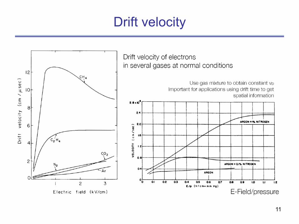
Drift velocity
12
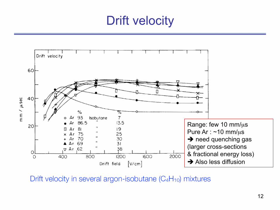
Drift velocity
Range: few 10 mm/µs Pure Ar : ~10 mm/µs è need quenching gas (larger cross-sections & fractional energy loss) è Also less diffusion
13
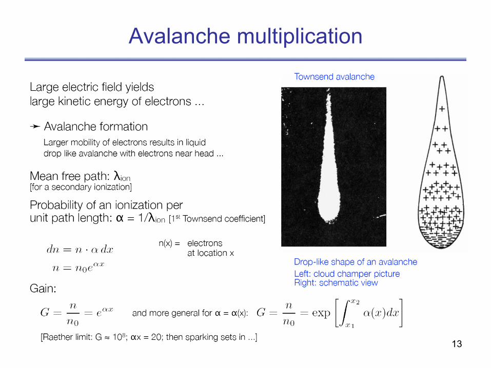
Avalanche multiplication
14
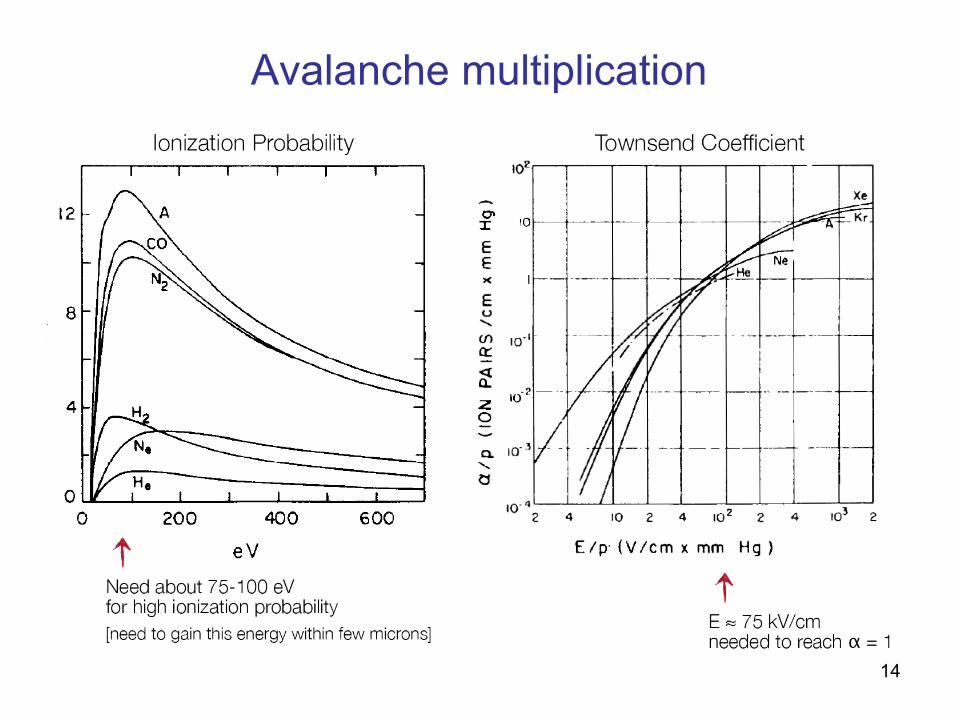
Avalanche multiplication
15
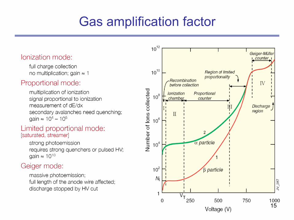
Gas amplification factor
16
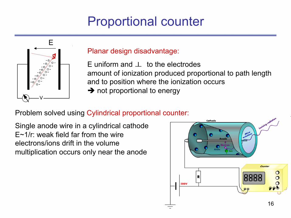
Proportional counter
Planar design disadvantage:
E uniform and to the electrodes amount of ionization produced proportional to path length and to position where the ionization occurs è not proportional to energy
E
Problem solved using Cylindrical proportional counter:
Single anode wire in a cylindrical cathode E~1/r: weak field far from the wire electrons/ions drift in the volume multiplication occurs only near the anode
⊥
17
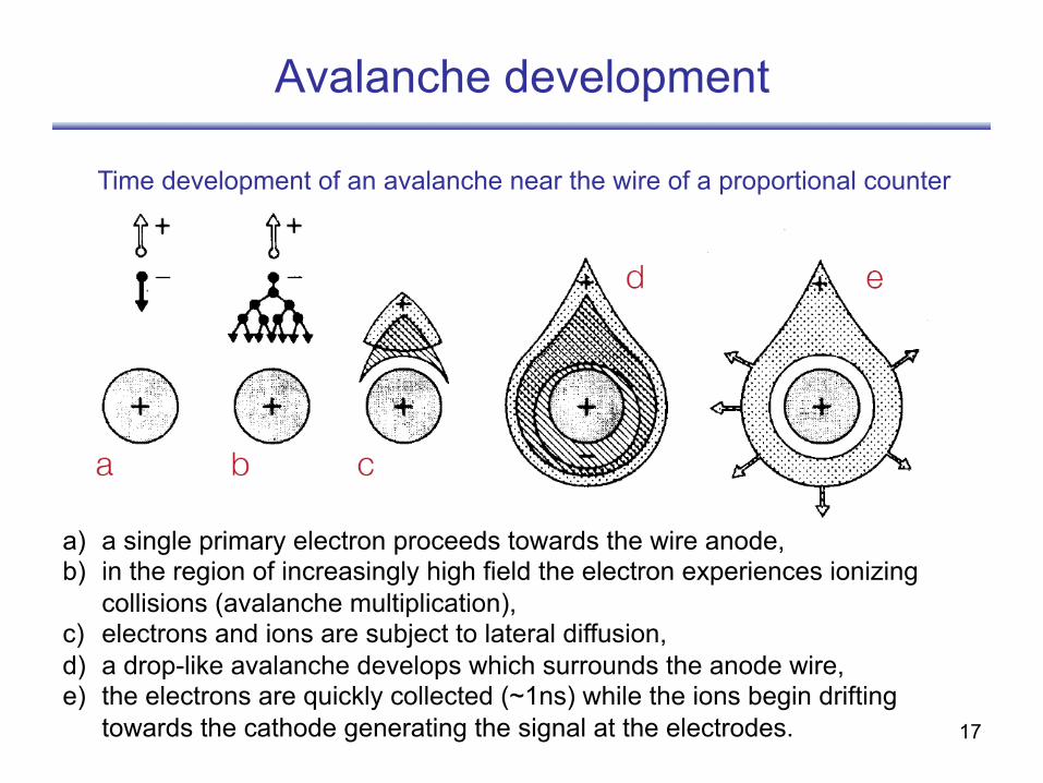
Avalanche development
a) a single primary electron proceeds towards the wire anode, b) in the region of increasingly high field the electron experiences ionizing
collisions (avalanche multiplication), c) electrons and ions are subject to lateral diffusion, d) a drop-like avalanche develops which surrounds the anode wire, e) the electrons are quickly collected (~1ns) while the ions begin drifting
towards the cathode generating the signal at the electrodes.
Time development of an avalanche near the wire of a proportional counter
18
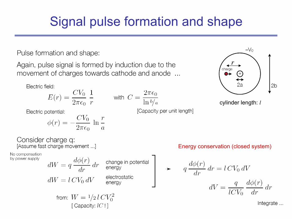
Signal pulse formation and shape
r
Energy conservation (closed system)
cylinder length: l
19
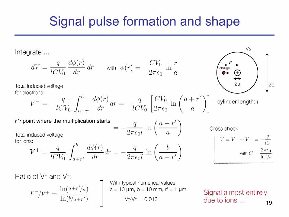
Signal pulse formation and shape
r
r’: point where the multiplication starts
cylinder length: l
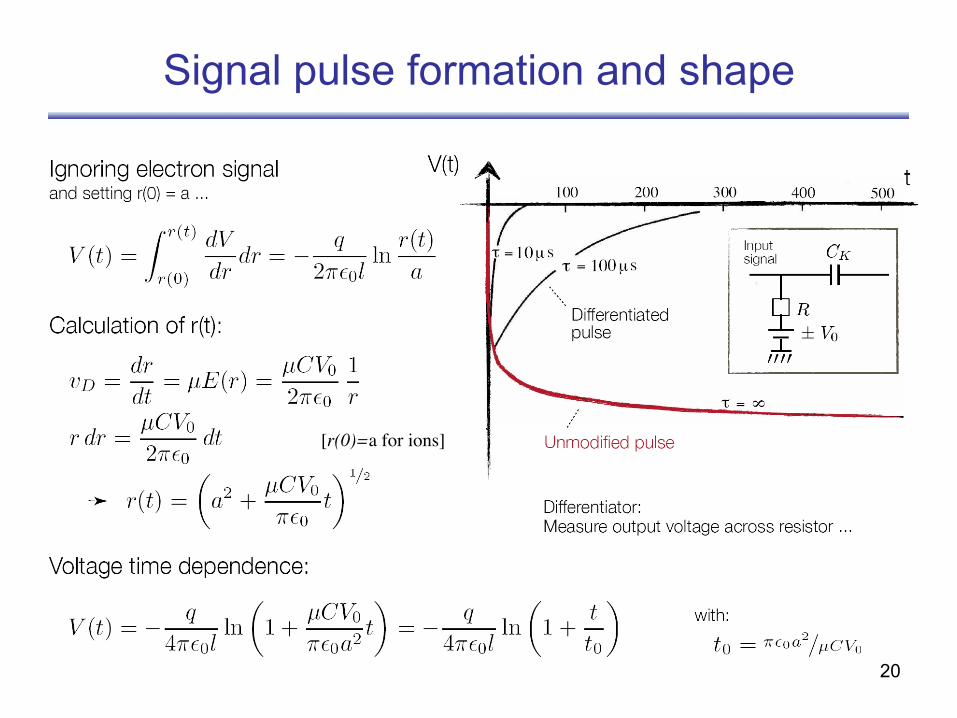
20
Signal pulse formation and shape
[r(0)=a for ions]
21
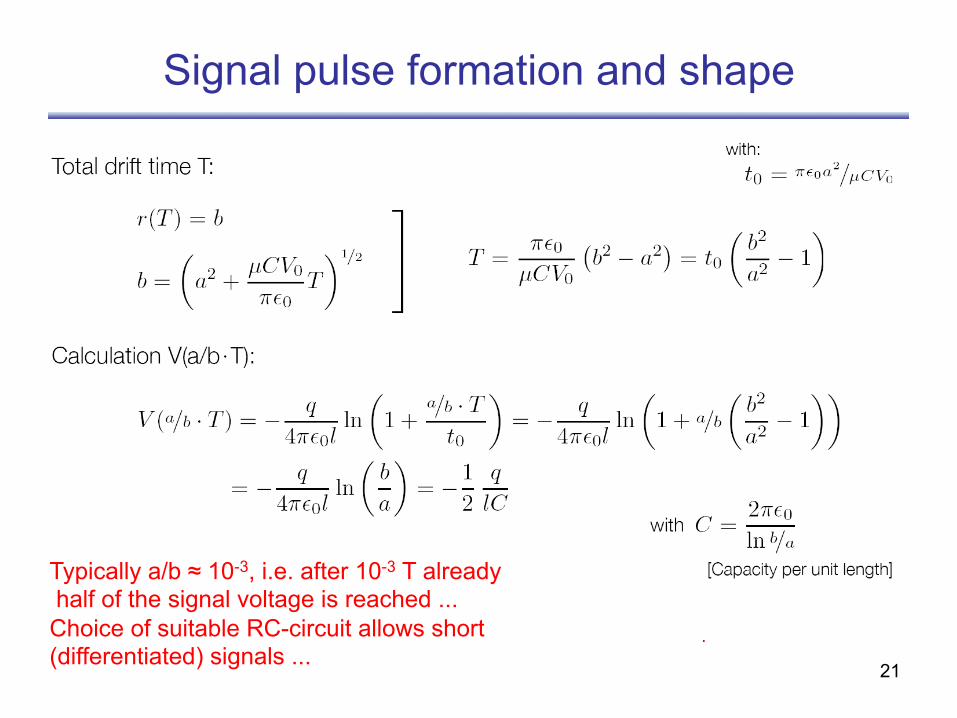
Signal pulse formation and shape
Typically a/b ≈ 10-3, i.e. after 10-3 T already half of the signal voltage is reached ... Choice of suitable RC-circuit allows short (differentiated) signals ...
22
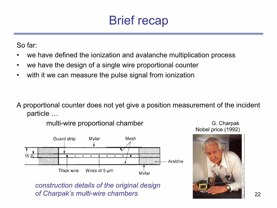
Brief recap
So far: • we have defined the ionization and avalanche multiplication process • we have the design of a single wire proportional counter • with it we can measure the pulse signal from ionization
A proportional counter does not yet give a position measurement of the incident particle … multi-wire proportional chamber
construction details of the original design of Charpak’s multi-wire chambers
G. Charpak Nobel price (1992)
23
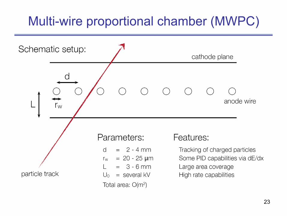
Multi-wire proportional chamber (MWPC)
24
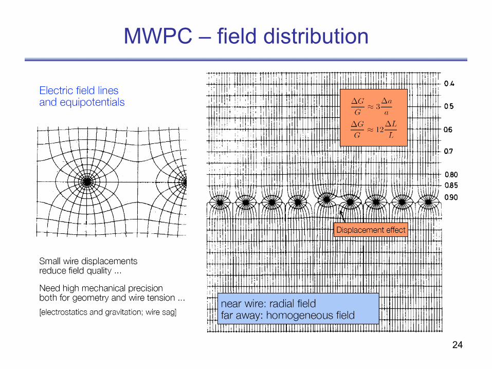
MWPC – field distribution
25
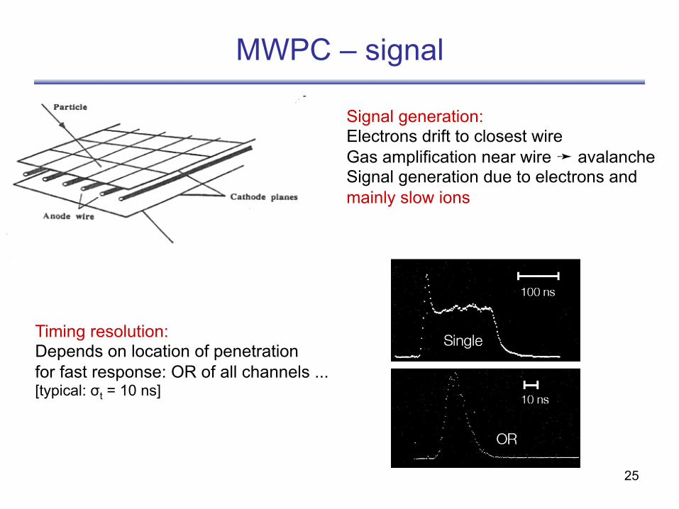
MWPC – signal
Signal generation: Electrons drift to closest wire Gas amplification near wire ➛ avalanche Signal generation due to electrons and mainly slow ions
Timing resolution: Depends on location of penetration for fast response: OR of all channels ... [typical: σt = 10 ns]
26
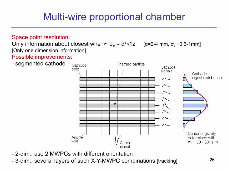
Space point resolution: Only information about closest wire ➛ σx = d/√12 [d=2-4 mm, σx ~0.6-1mm] [Only one dimension information] Possible improvements: - segmented cathode
- 2-dim.: use 2 MWPCs with different orientation - 3-dim.: several layers of such X-Y-MWPC combinations [tracking]
Multi-wire proportional chamber
27
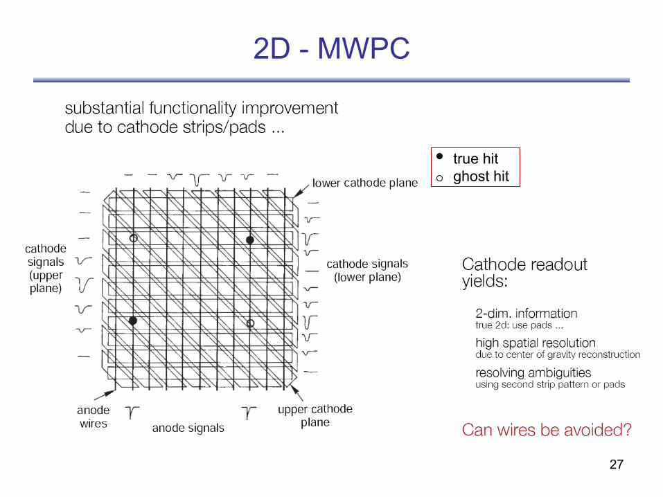
2D - MWPC
true hit ghost hit
28
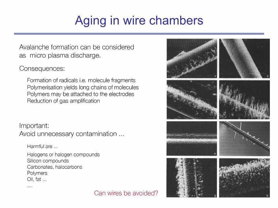
Aging in wire chambers
29
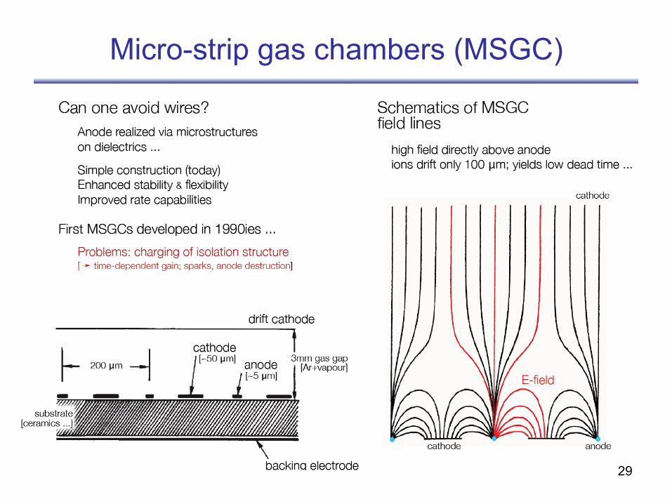
Micro-strip gas chambers (MSGC)
30
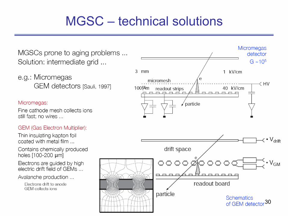
MGSC – technical solutions
µ
31
Drift chamber
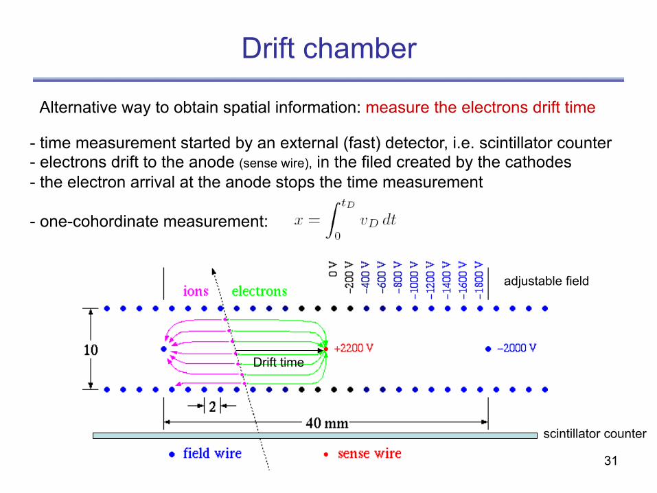
Alternative way to obtain spatial information: measure the electrons drift time
- time measurement started by an external (fast) detector, i.e. scintillator counter - electrons drift to the anode (sense wire), in the filed created by the cathodes - the electron arrival at the anode stops the time measurement
- one-cohordinate measurement:
scintillator counter
Drift time
adjustable field
32
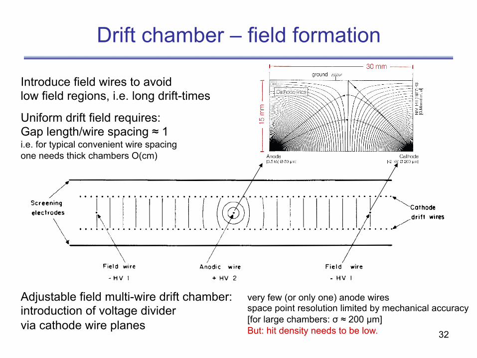
Drift chamber – field formation
Introduce field wires to avoid low field regions, i.e. long drift-times
Uniform drift field requires: Gap length/wire spacing ≈ 1 i.e. for typical convenient wire spacing one needs thick chambers O(cm)
Adjustable field multi-wire drift chamber: introduction of voltage divider via cathode wire planes
very few (or only one) anode wires space point resolution limited by mechanical accuracy [for large chambers: σ ≈ 200 µm] But: hit density needs to be low.
33
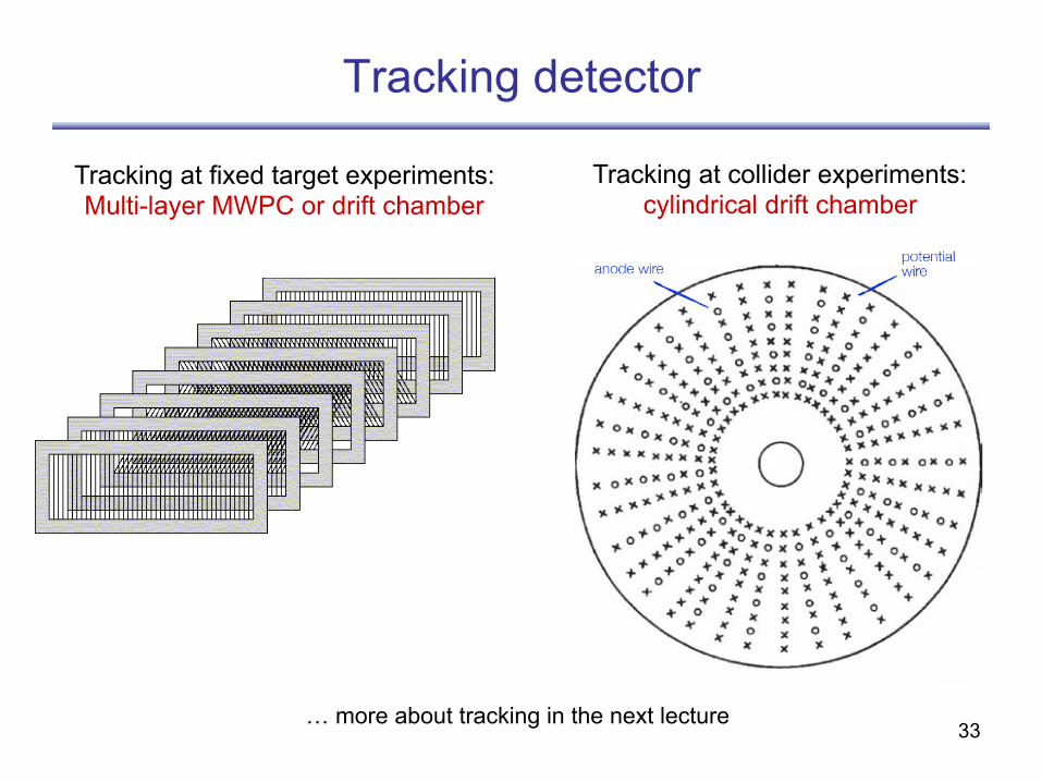
Tracking detector
Tracking at collider experiments: cylindrical drift chamber
Tracking at fixed target experiments: Multi-layer MWPC or drift chamber
… more about tracking in the next lecture
34
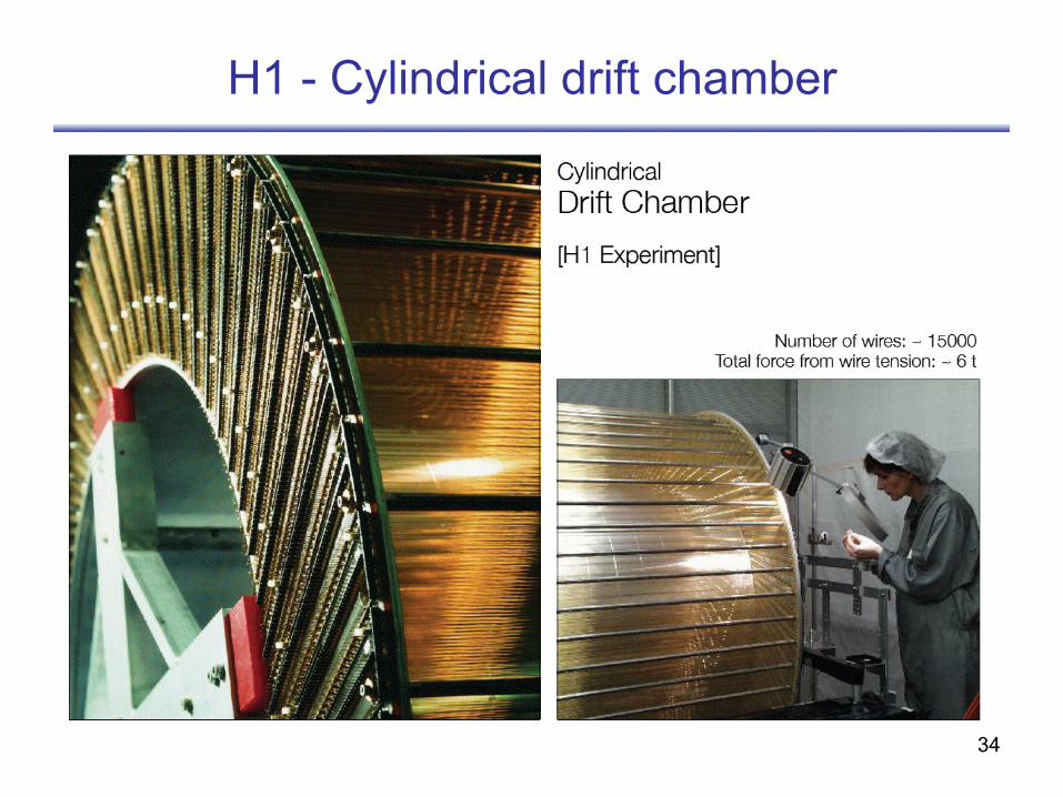
H1 - Cylindrical drift chamber
35
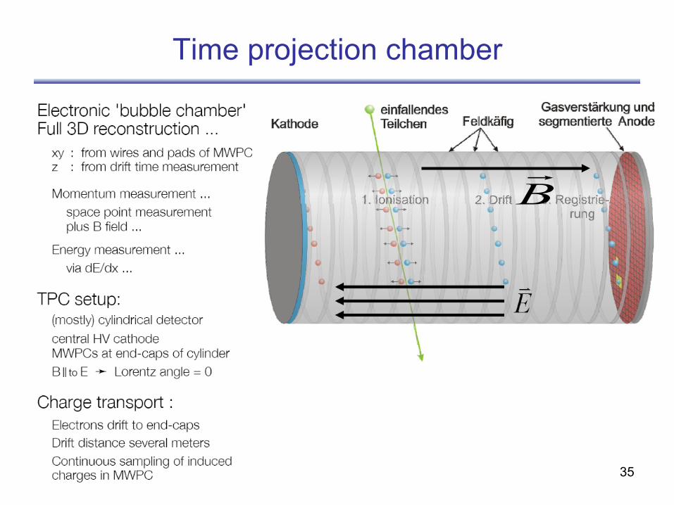
Time projection chamber
B
36
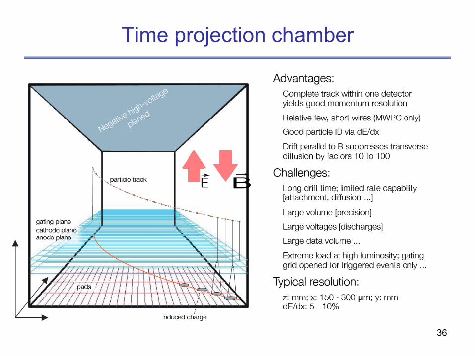
Time projection chamber
B
37
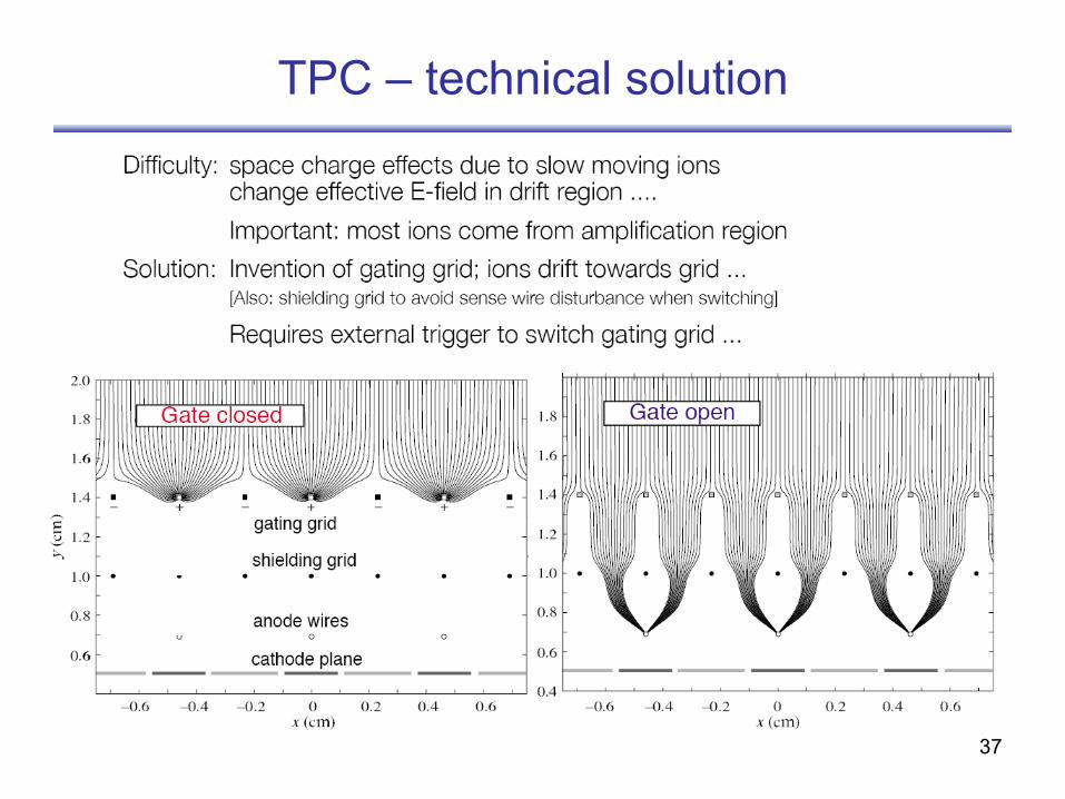
TPC – technical solution
38
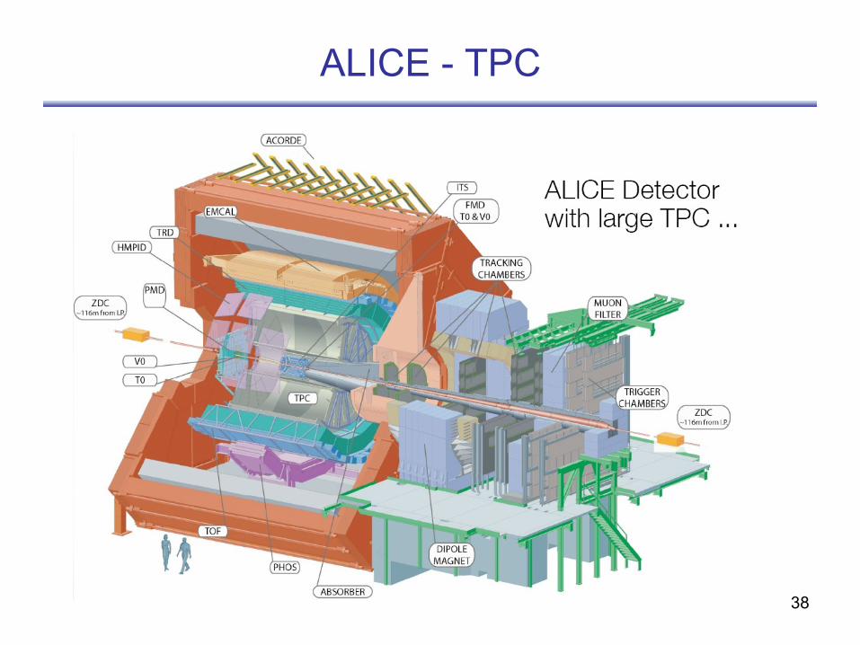
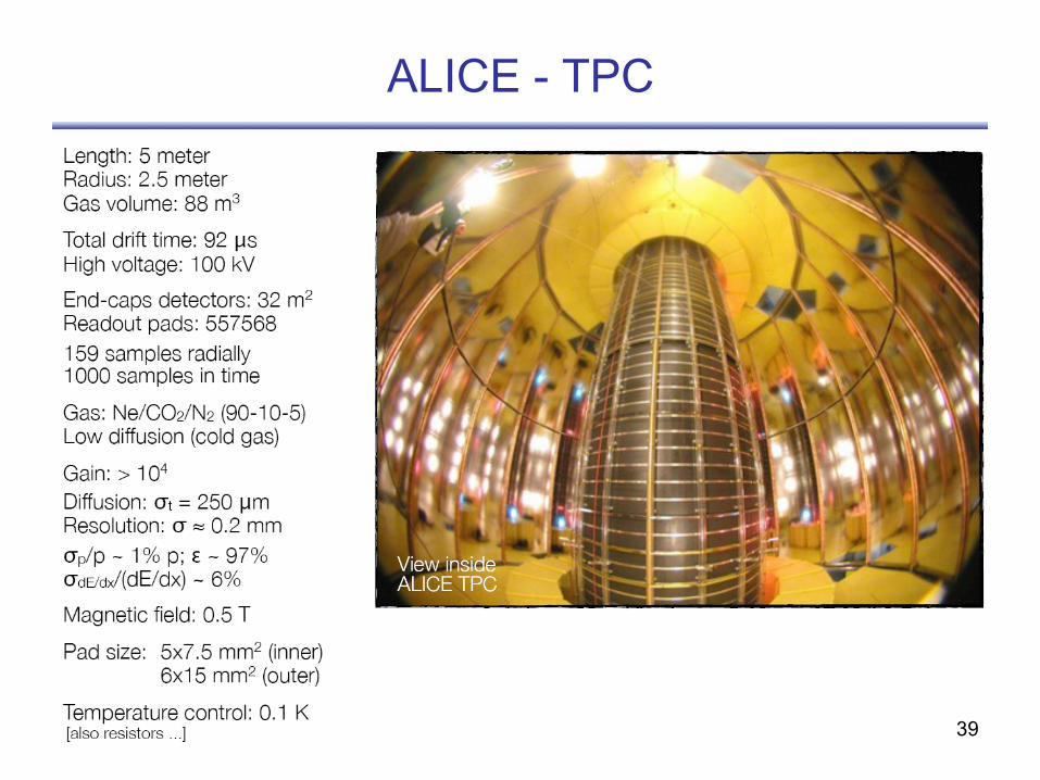
ALICE - TPC
39
ALICE - TPC