First User Experiments at the VUV-FELat DESY · First User Experiments at the VUV-FEL at DESY Josef...
37
First User Experiments at the VUV-FEL at DESY Josef Feldhaus 4th Generation Light Sources and Ultrafast Phenomena, Trieste, December 14-15, 2005 • Overview of the facility • Status and characteristics of the VUV-FEL • First user experiments: overview and some examples
Transcript of First User Experiments at the VUV-FELat DESY · First User Experiments at the VUV-FEL at DESY Josef...
First User Experiments at the VUV-FEL at DESY
Josef Feldhaus
4th Generation Light Sources and Ultrafast Phenomena, Trieste, December 14-15, 2005
• Overview of the facility
• Status and characteristics of the VUV-FEL
• First user experiments: overview and some examples
Photon energy ~20-200 eV Bandwidth ∆λ/λ~0.5 %Peak power >1 GWPulse duration ∼100 fsPulses per second up to 72000
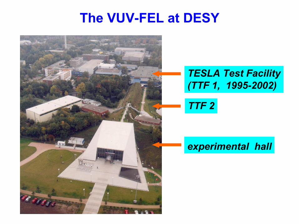
TESLA Test Facility(TTF 1, 1995-2002)
TTF 2
experimental hall
The VUV-FEL at DESY
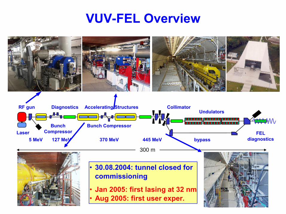
300 m
VUV-FEL Overview
• 30.08.2004: tunnel closed for commissioning
• Jan 2005: first lasing at 32 nm• Aug 2005: first user exper.
LaserBunch Compressor
bypass
UndulatorsCollimator
Bunch Compressor
RF gun
5 MeV 127 MeV 370 MeV 445 MeV
Accelerating StructuresDiagnostics
FEL diagnostics
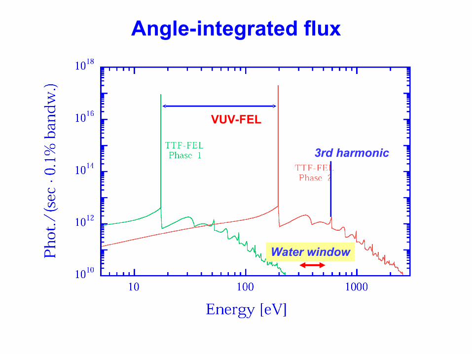
Angle-integrated flux
VUV-FEL
3rd harmonic
Water window
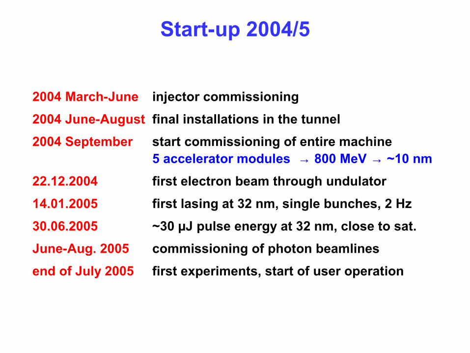
Start-up 2004/5
2004 March-June injector commissioning2004 June-August final installations in the tunnel2004 September start commissioning of entire machine
5 accelerator modules → 800 MeV → ~10 nm22.12.2004 first electron beam through undulator 14.01.2005 first lasing at 32 nm, single bunches, 2 Hz30.06.2005 ~30 µJ pulse energy at 32 nm, close to sat.June-Aug. 2005 commissioning of photon beamlinesend of July 2005 first experiments, start of user operation
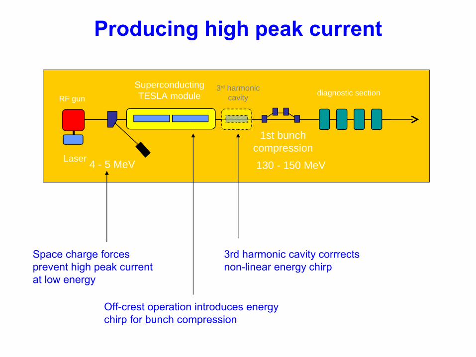
Producing high peak current
Laser
RF gun
4 - 5 MeV 130 - 150 MeV
1st bunch compression
Superconducting TESLA module
3rd harmonic cavity
diagnostic section
Space charge forces prevent high peak current at low energy
3rd harmonic cavity corrrects non-linear energy chirp
Off-crest operation introduces energy chirp for bunch compression
time/longitudinal position
head
tail
tail
tailhead
headhead
tail
tailhead
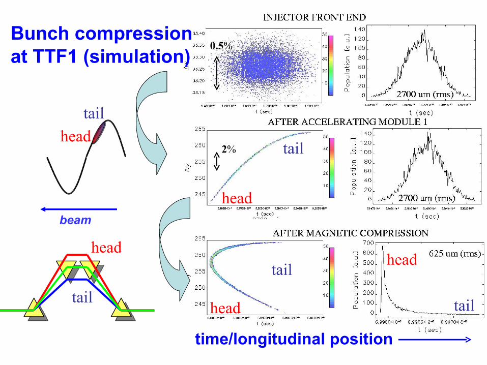
0.5%
2%
Bunch compression at TTF1 (simulation)
beam
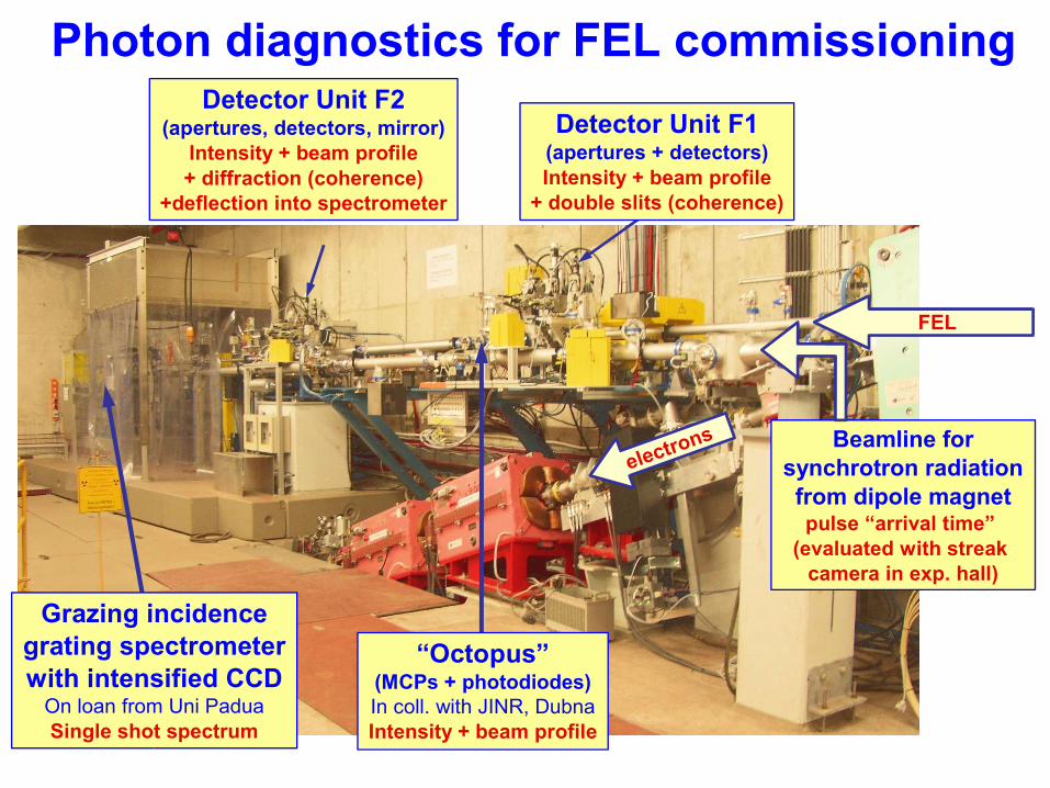
Photon diagnostics for FEL commissioningDetector Unit F2
(apertures, detectors, mirror)Intensity + beam profile+ diffraction (coherence)
+deflection into spectrometer
Detector Unit F1(apertures + detectors)Intensity + beam profile
+ double slits (coherence)
Grazing incidencegrating spectrometerwith intensified CCD
On loan from Uni PaduaSingle shot spectrum
“Octopus”(MCPs + photodiodes)In coll. with JINR, DubnaIntensity + beam profile
FEL
electrons Beamline forsynchrotron radiationfrom dipole magnetpulse “arrival time”
(evaluated with streak camera in exp. hall)
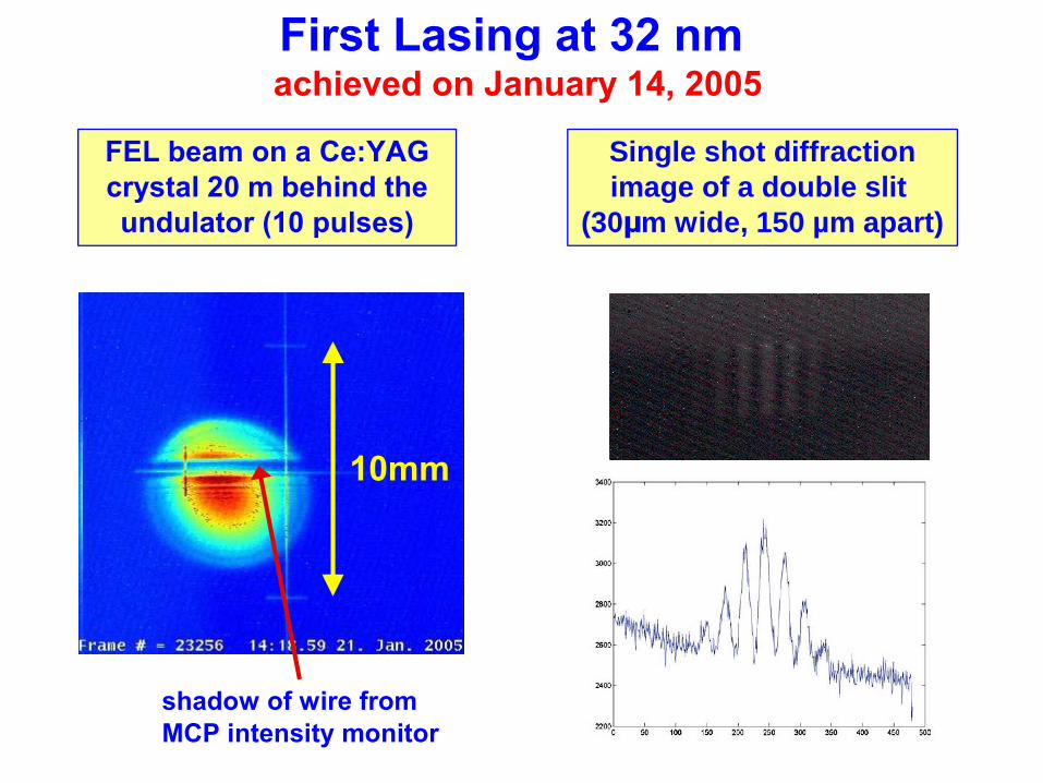
First Lasing at 32 nm achieved on January 14, 2005
10mm
shadow of wire from MCP intensity monitor
FEL beam on a Ce:YAG crystal 20 m behind the undulator (10 pulses)
Single shot diffraction image of a double slit
(30μm wide, 150 µm apart)
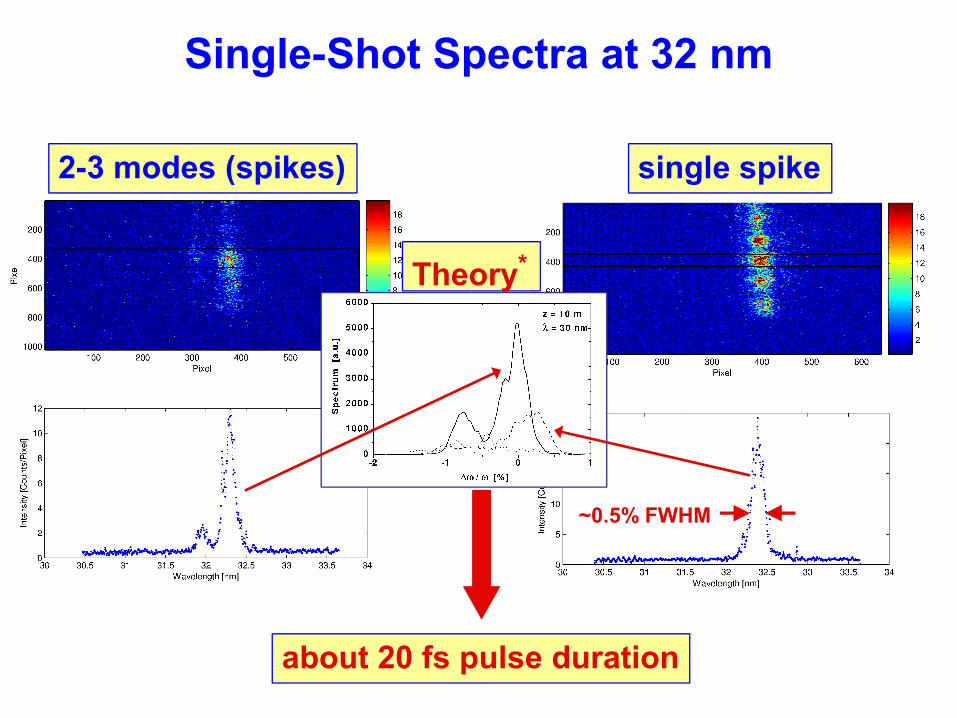
Single-Shot Spectra at 32 nm
2-3 modes (spikes) single spike
Theory*
~0.5% FWHM
about 20 fs pulse duration
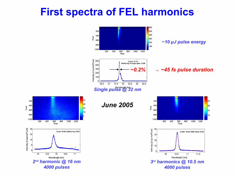
First spectra of FEL harmonics
June 2005
~10 µJ pulse energy
Single pulse @ 32 nm
~0.2% → ~45 fs pulse duration
2nd harmonic @ 16 nm4000 pulses
3rd harmonics @ 10.5 nm4000 pulses
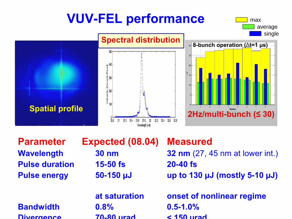
Parameter Expected (08.04) MeasuredWavelength 30 nm 32 nm (27, 45 nm at lower int.)Pulse duration 15-50 fs 20-40 fsPulse energy 50-150 µJ up to 130 µJ (mostly 5-10 µJ)
at saturation onset of nonlinear regime
Bandwidth 0.8% 0.5-1.0%Divergence 70-80 µrad < 150 µrad
Spectral distribution
2Hz/multi-bunch (≤ 30)
8-bunch operation (∆t=1 µs)
VUV-FEL performance
Spatial profile
maxaverage
single
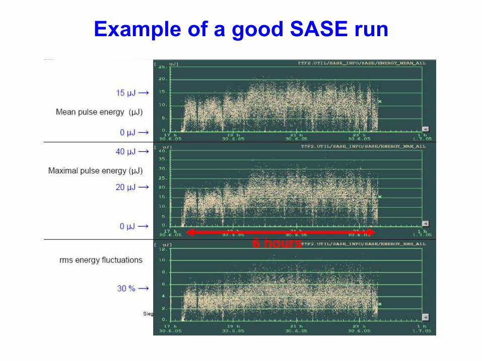
Example of a good SASE run
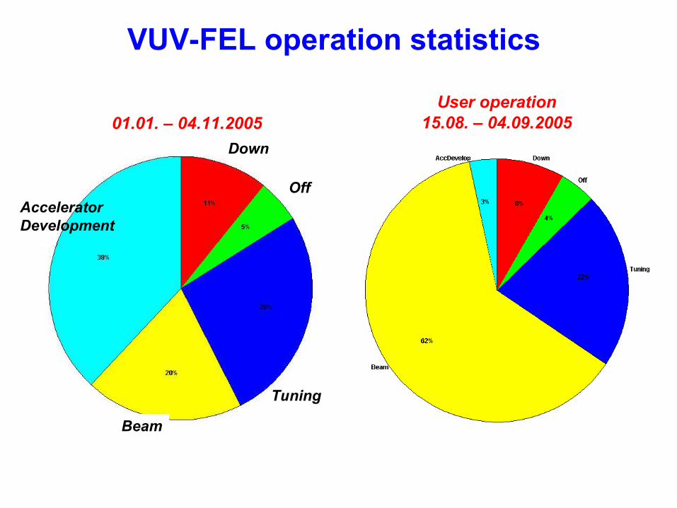
VUV-FEL operation statistics
01.01. – 04.11.2005User operation
15.08. – 04.09.2005
Accelerator Development
Beam
Off
Down
Tuning
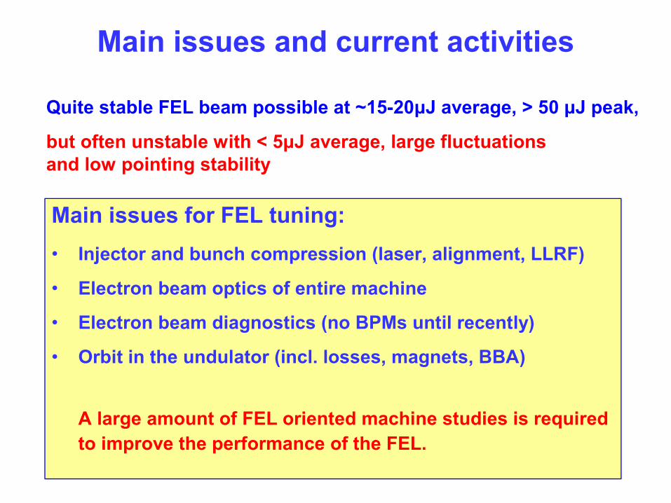
Main issues and current activities
Quite stable FEL beam possible at ~15-20μJ average, > 50 μJ peak,
but often unstable with < 5μJ average, large fluctuations and low pointing stability
Main issues for FEL tuning:• Injector and bunch compression (laser, alignment, LLRF)
• Electron beam optics of entire machine
• Electron beam diagnostics (no BPMs until recently)
• Orbit in the undulator (incl. losses, magnets, BBA)
A large amount of FEL oriented machine studies is required to improve the performance of the FEL.
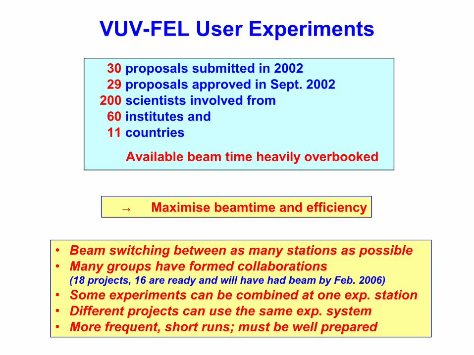
VUV-FEL User Experiments
30 proposals submitted in 2002 29 proposals approved in Sept. 2002 200 scientists involved from 60 institutes and 11 countries
Available beam time heavily overbooked
• Beam switching between as many stations as possible• Many groups have formed collaborations
(18 projects, 16 are ready and will have had beam by Feb. 2006)• Some experiments can be combined at one exp. station• Different projects can use the same exp. system• More frequent, short runs; must be well prepared
→ Maximise beamtime and efficiency
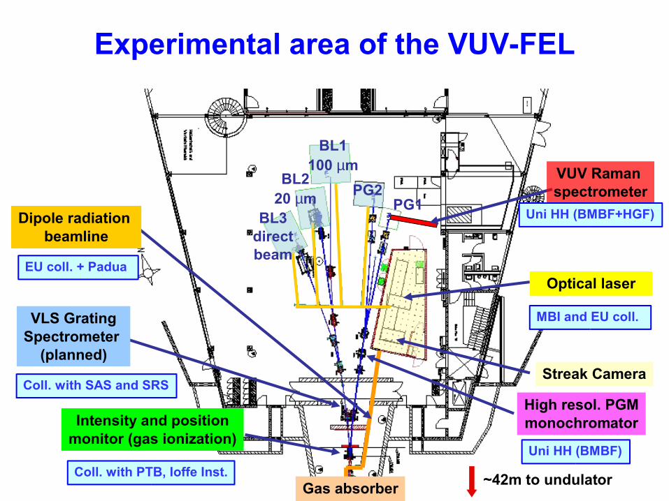
Experimental area of the VUV-FEL
BL3directbeam
BL220 µm
BL1100 µm
PG2PG1
High resol. PGMmonochromatorIntensity and position
monitor (gas ionization)
~42m to undulator
Streak Camera
Gas absorber
Coll. with SAS and SRS
Coll. with PTB, Ioffe Inst.
MBI and EU coll.
Optical laser
Uni HH (BMBF)
EU coll. + Padua
Dipole radiation beamline
VLS GratingSpectrometer
(planned)
VUV Raman spectrometer
Uni HH (BMBF+HGF)
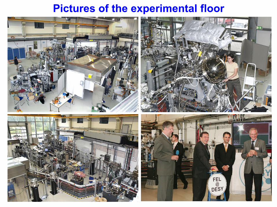
Pictures of the experimental floor
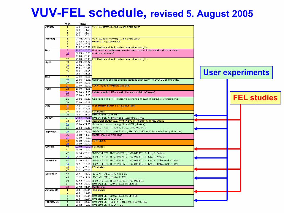
VUV-FEL schedule, revised 5. August 2005
FEL studies
User experiments
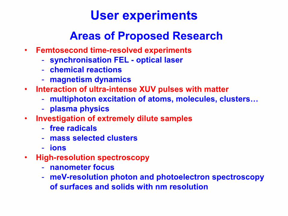
User experimentsAreas of Proposed Research
• Femtosecond time-resolved experiments- synchronisation FEL - optical laser- chemical reactions - magnetism dynamics
• Interaction of ultra-intense XUV pulses with matter- multiphoton excitation of atoms, molecules, clusters…- plasma physics
• Investigation of extremely dilute samples- free radicals- mass selected clusters- ions
• High-resolution spectroscopy- nanometer focus- meV-resolution photon and photoelectron spectroscopy
of surfaces and solids with nm resolution
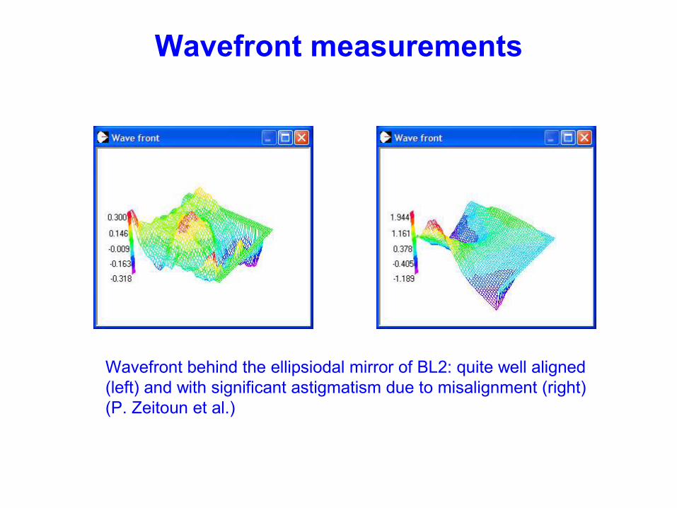
Wavefront measurements
Wavefront behind the ellipsiodal mirror of BL2: quite well aligned (left) and with significant astigmatism due to misalignment (right)(P. Zeitoun et al.)
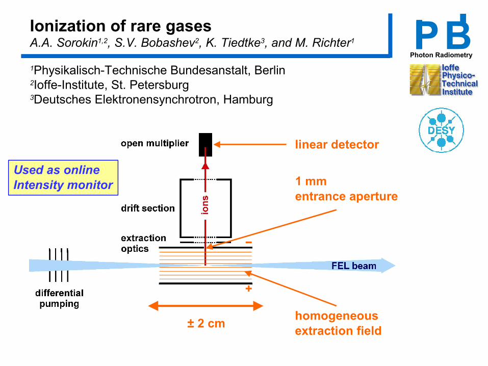
−
+
homogeneousextraction field
1 mm entrance aperture
linear detector
± 2 cm
Ionization of rare gases A.A. Sorokin1,2, S.V. Bobashev2, K. Tiedtke3, and M. Richter1
1Physikalisch-Technische Bundesanstalt, Berlin2Ioffe-Institute, St. Petersburg3Deutsches Elektronensynchrotron, Hamburg
Photon RadiometryPBI I
Used as online Intensity monitor
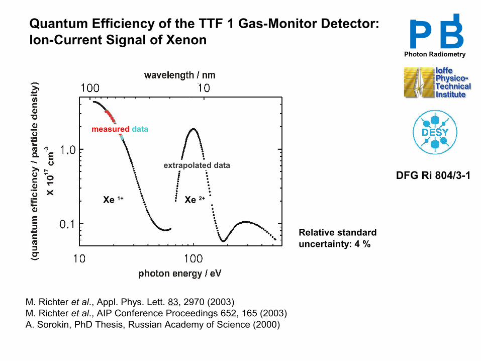
Relative standarduncertainty: 4 %
extrapolated data
measured data
Xe 1+ Xe 2+
M. Richter et al., Appl. Phys. Lett. 83, 2970 (2003)M. Richter et al., AIP Conference Proceedings 652, 165 (2003)A. Sorokin, PhD Thesis, Russian Academy of Science (2000)
Quantum Efficiency of the TTF 1 Gas-Monitor Detector: Ion-Current Signal of Xenon
DFG Ri 804/3-1
Photon RadiometryPBI I
( )++ −= NN
AdNdN
ph
σ
+
−≈
−=⇒ −
+
2σ σ61σ
211σ1)( A
NAN
phphphphA
phN
NzneNNN
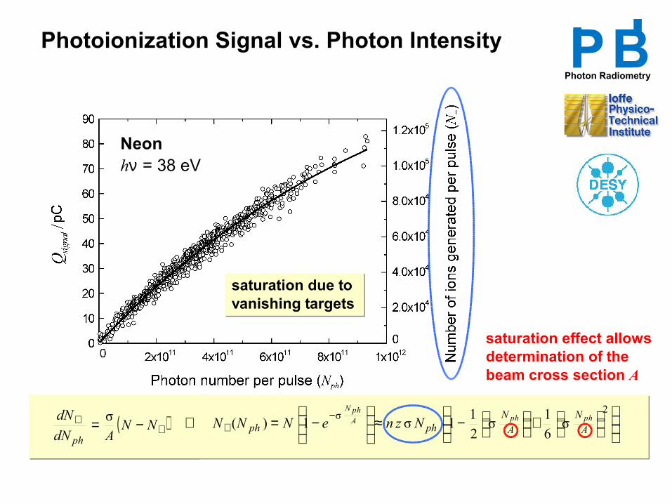
Neonhν = 38 eV
Photoionization Signal vs. Photon Intensity
saturation effect allows determination of the beam cross section A
saturation due to vanishing targets
Photon RadiometryPBI I
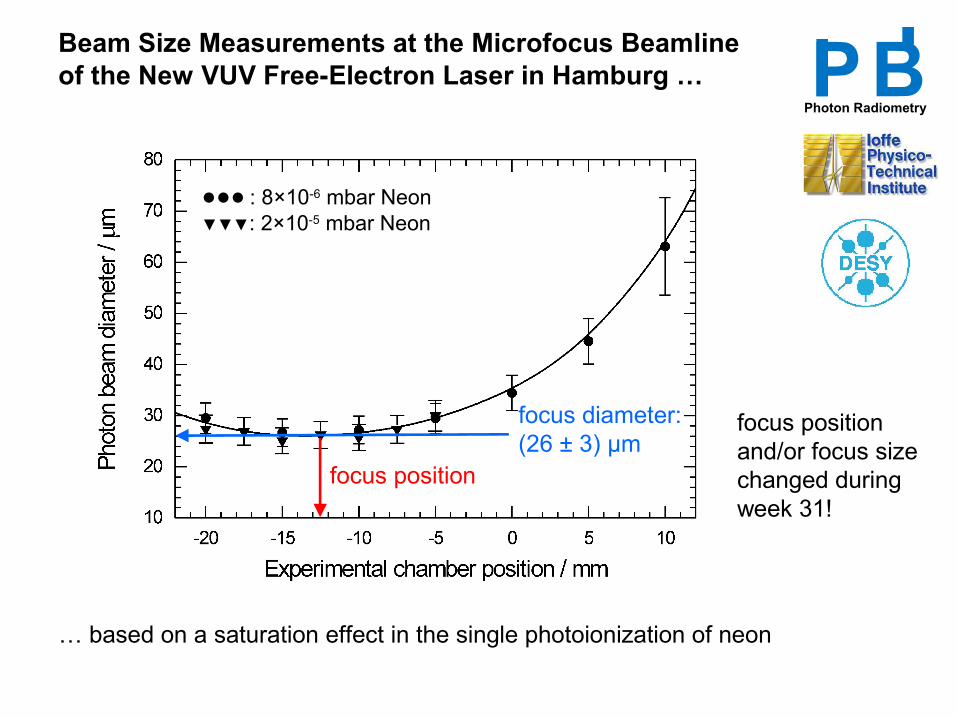
Beam Size Measurements at the Microfocus Beamline of the New VUV Free-Electron Laser in Hamburg …
… based on a saturation effect in the single photoionization of neon
focus position
focus diameter: (26 ± 3) µm
●●● : 8×10⁻⁶ mbar Neon▼▼▼: 2×10⁻⁵ mbar Neon
focus positionand/or focus sizechanged duringweek 31!
Photon RadiometryPBI I
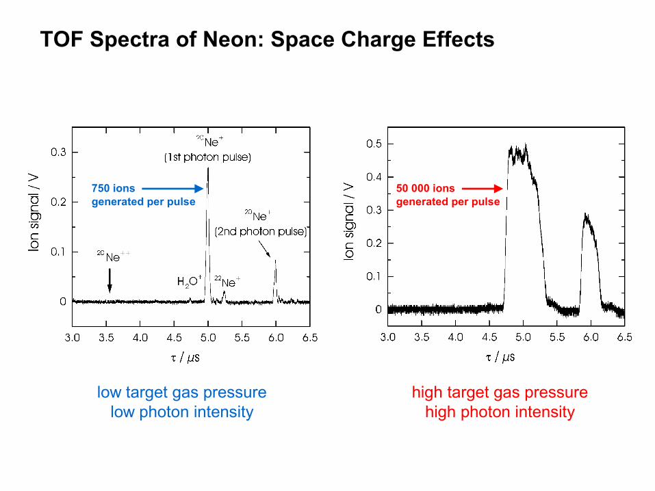
TOF Spectra of Neon: Space Charge Effects
low target gas pressurelow photon intensity
high target gas pressurehigh photon intensity
750 ions generated per pulse
50 000 ions generated per pulse
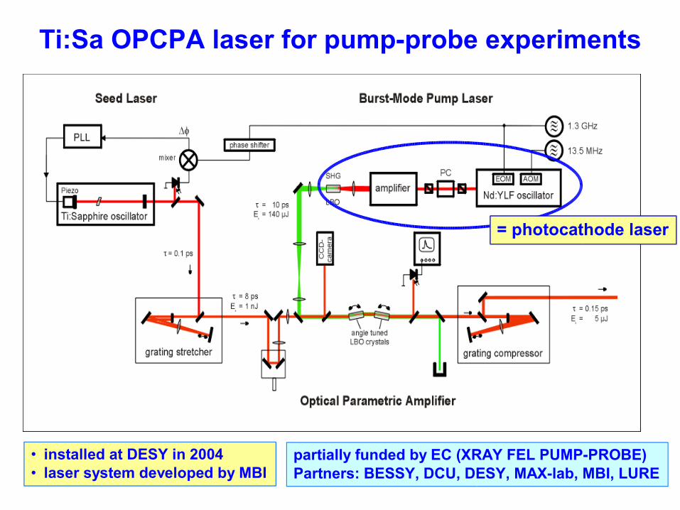
Ti:Sa OPCPA laser for pump-probe experiments
• installed at DESY in 2004• laser system developed by MBI
= photocathode laser
partially funded by EC (XRAY FEL PUMP-PROBE)Partners: BESSY, DCU, DESY, MAX-lab, MBI, LURE
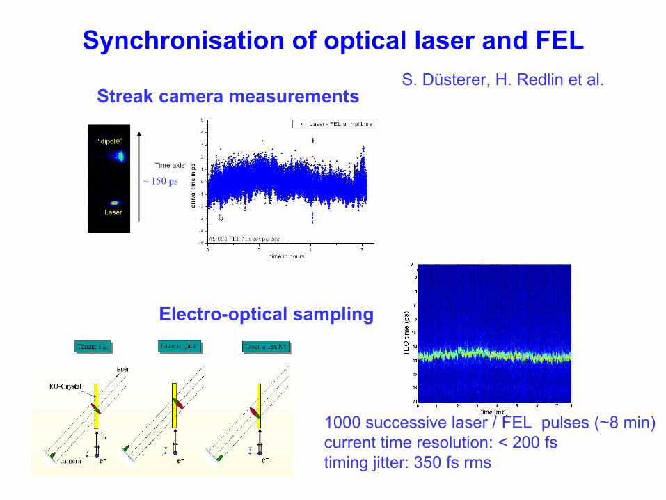
Synchronisation of optical laser and FEL
Electro-optical sampling
S. Düsterer, H. Redlin et al.
1000 successive laser / FEL pulses (~8 min) current time resolution: < 200 fs timing jitter: 350 fs rms
Streak camera measurements
~ 150 ps
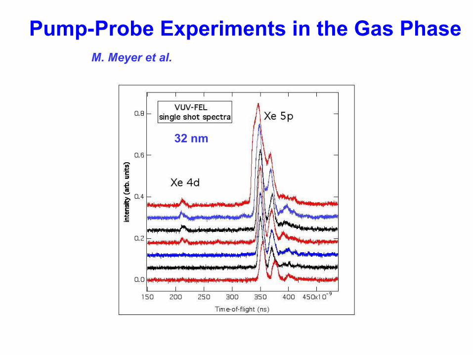
Pump-Probe Experiments in the Gas Phase
32 nm
M. Meyer et al.
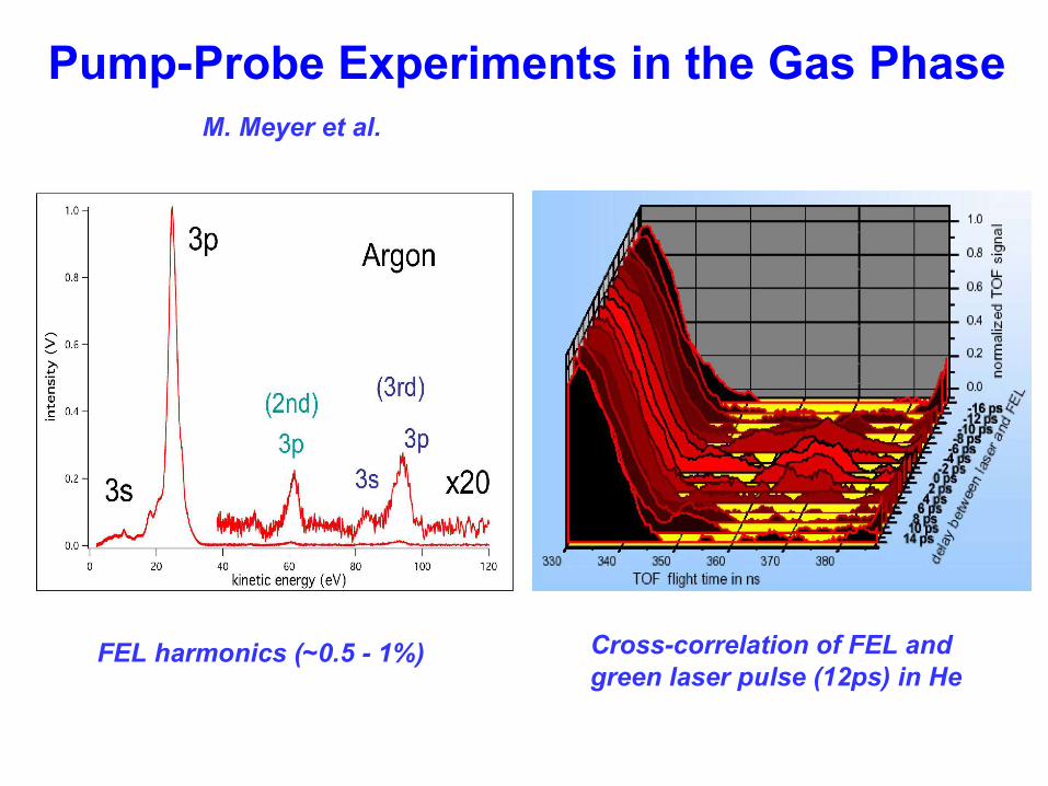
Pump-Probe Experiments in the Gas Phase
FEL harmonics (~0.5 - 1%) Cross-correlation of FEL and green laser pulse (12ps) in He
M. Meyer et al.
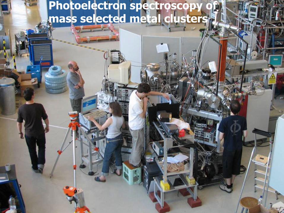
Photoelectron spectroscopy of mass selected metal clusters
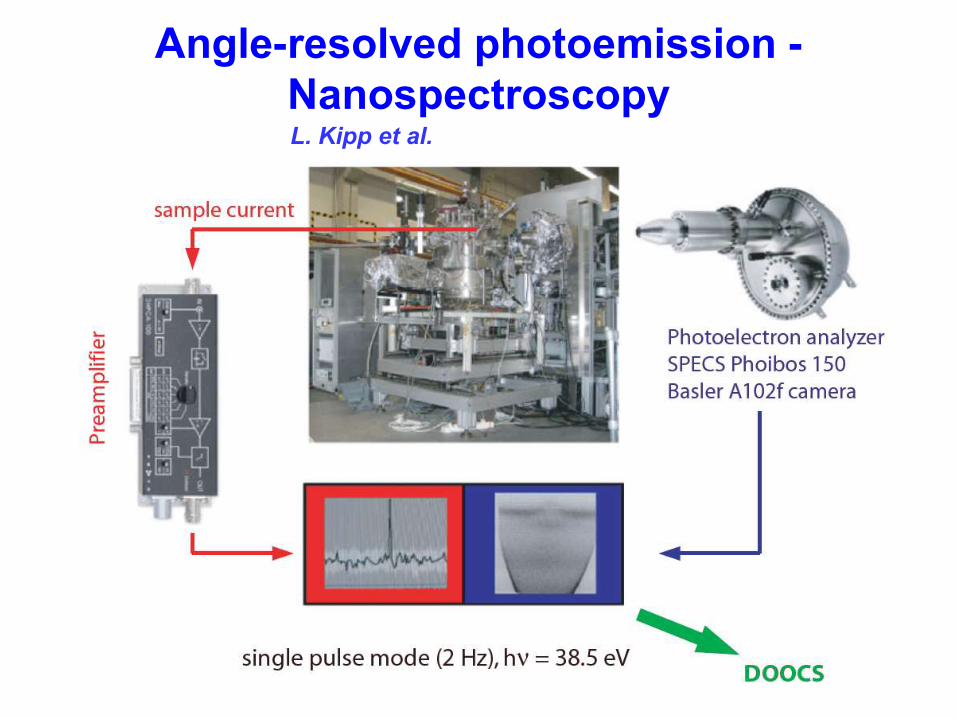
Angle-resolved photoemission - NanospectroscopyL. Kipp et al.
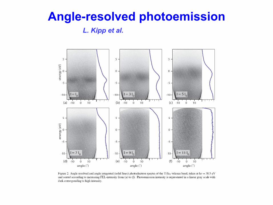
Angle-resolved photoemissionL. Kipp et al.
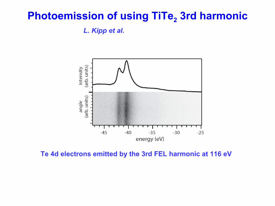
Photoemission of using TiTe2 3rd harmonicL. Kipp et al.
Te 4d electrons emitted by the 3rd FEL harmonic at 116 eV
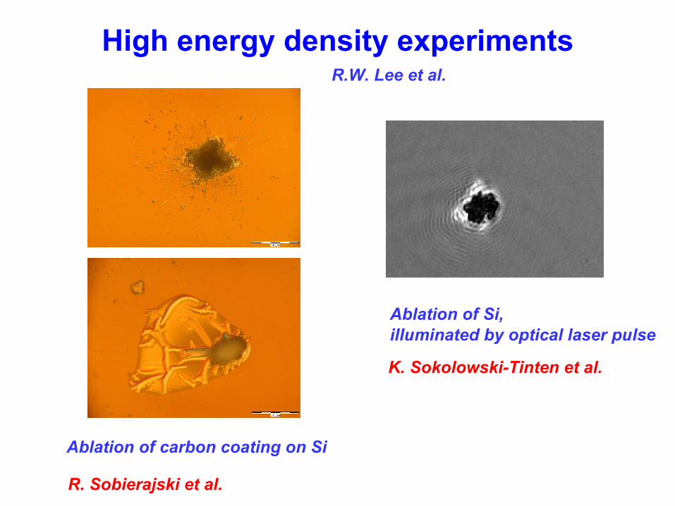
High energy density experiments
R. Sobierajski et al.
Ablation of carbon coating on Si
Ablation of Si, illuminated by optical laser pulse
K. Sokolowski-Tinten et al.
R.W. Lee et al.
Summary of user experiments
• ~ 12 user experiments had first beam• 4 experiments for technical developments were performed• Most experiments are very complex and include many
components – groups formed collaborations– teams are much larger than at synchrotron radiation facilities
• First reports are very promising:– commissioning of most experiments was quite successful
although often difficult with present FEL beam conditions– most experiments have taken first useful data demonstrating
that their concepts work; data are currently evaluated Thanks to good preparation and very intense user support• Continuing implementation of data acquisition and diagnostics
VUV-FEL operation after 2005
until end of 2006 - stable, reproducible operation from ~ 15 - 60 nm- operation with long bunch trains (up to 800 µs)
~ end of 2006? - install module ACC6, repair ACC5, replace ACC3 + 3rd harmonic RF system (FNAL, spring’07 ??) → 1 GeV → 6.5 nm → seeding operation
2007? - two-undulator seeding (?)- further extensions (FIR, exp. stations, …)
alternate periods of FEL commissioning/improvement and user experiments
e.g. 4 weeks commissioning, incl. 1 week photon beamlines and diagnostics, 4 weeks user operation
under discussion
The commissioning of the FEL is by far not completed