First results with the BRAMS interferometer & calibration ... · First results with the BRAMS...
45
First results with the BRAMS interferometer & calibration tests H. Lamy 1 , C. Tétard 1 , M. Anciaux 1 , S. Ranvier 1 , Antonio Martinez Picar 2 1 Royal Belgian Institute for Space Aeronomy 2 Royal Observatory of Belgium
Transcript of First results with the BRAMS interferometer & calibration ... · First results with the BRAMS...
First results with the BRAMS
interferometer & calibration
tests
H. Lamy1, C. Tétard1, M. Anciaux1, S. Ranvier1, Antonio
Martinez Picar2
1 Royal Belgian Institute for Space Aeronomy
2 Royal Observatory of Belgium
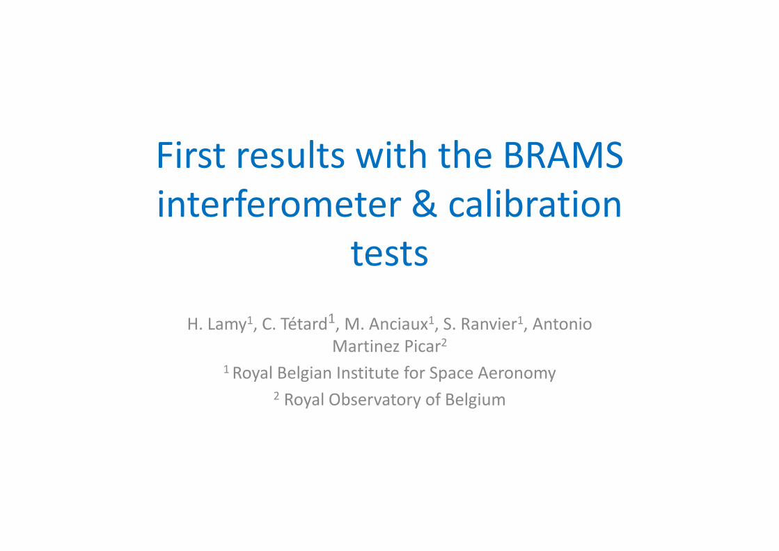
Typical BRAMS receiving station
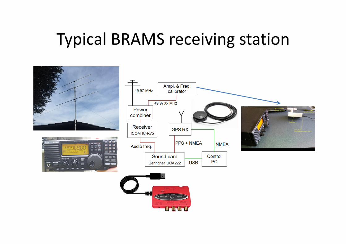
The interferometer in Humain
Credit : A. Martinez-Picar
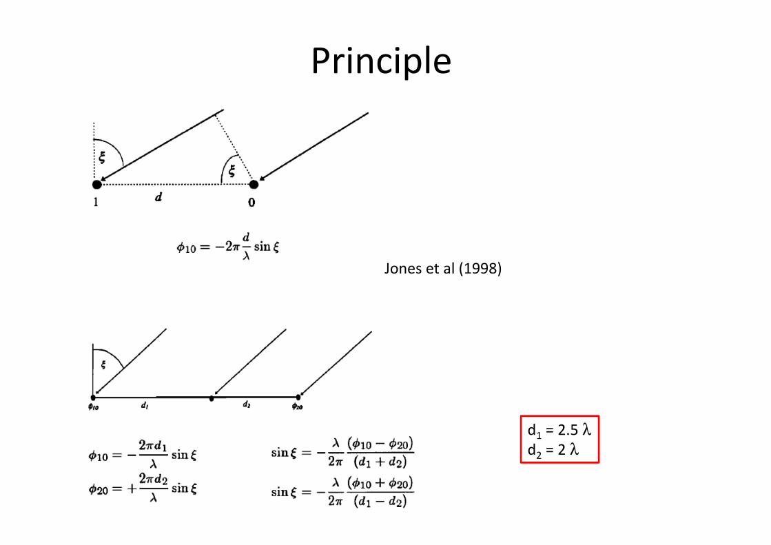
Principle
Jones et al (1998)
d1 = 2.5 λd2 = 2 λ
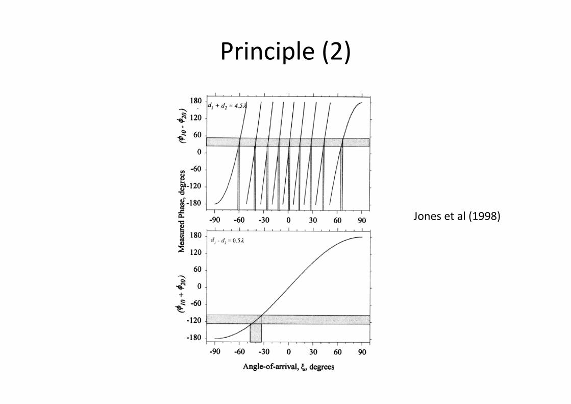
Principle (2)
Jones et al (1998)
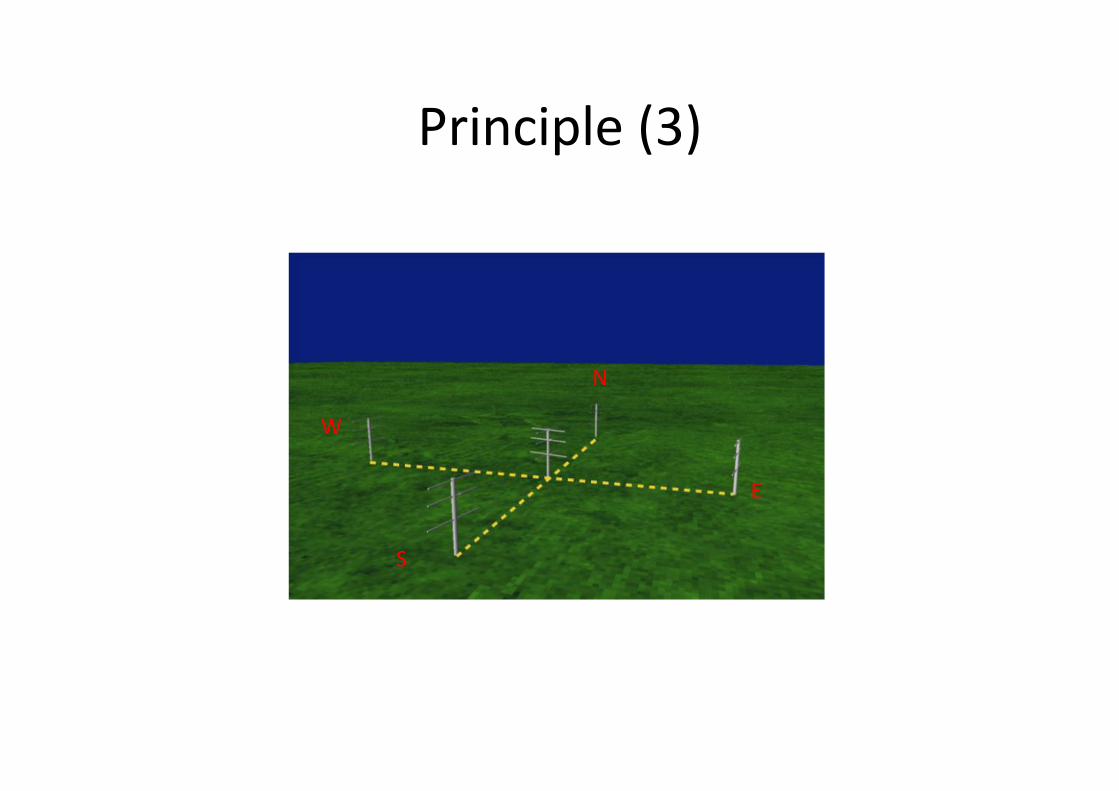
Principle (3)
N
S
E
W
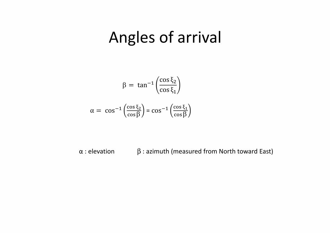
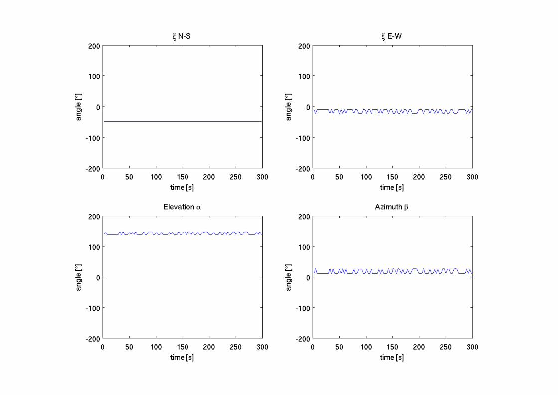
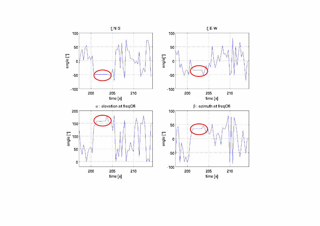
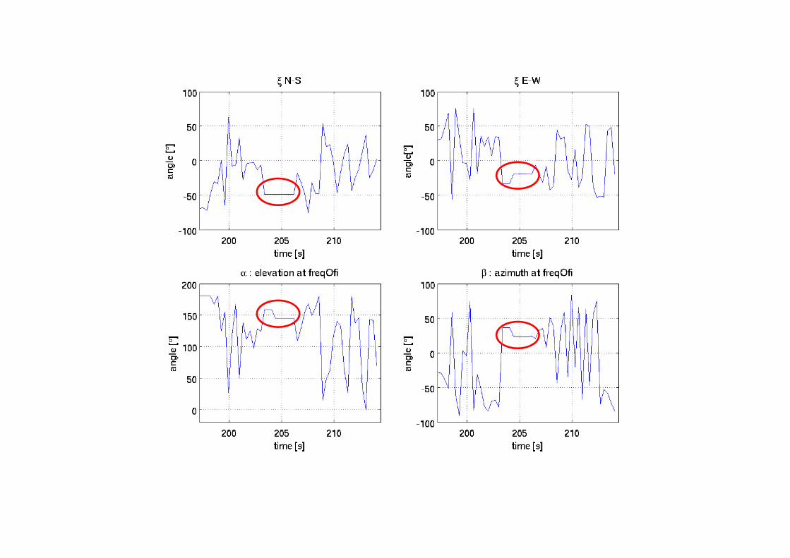
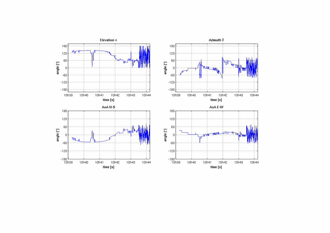
Angles of arrival
β = tan��cos ξ�
cos ξ�
α = cos����� ��
���β= cos��
��� ��
���β
α : elevation β : azimuth (measured from North toward East)
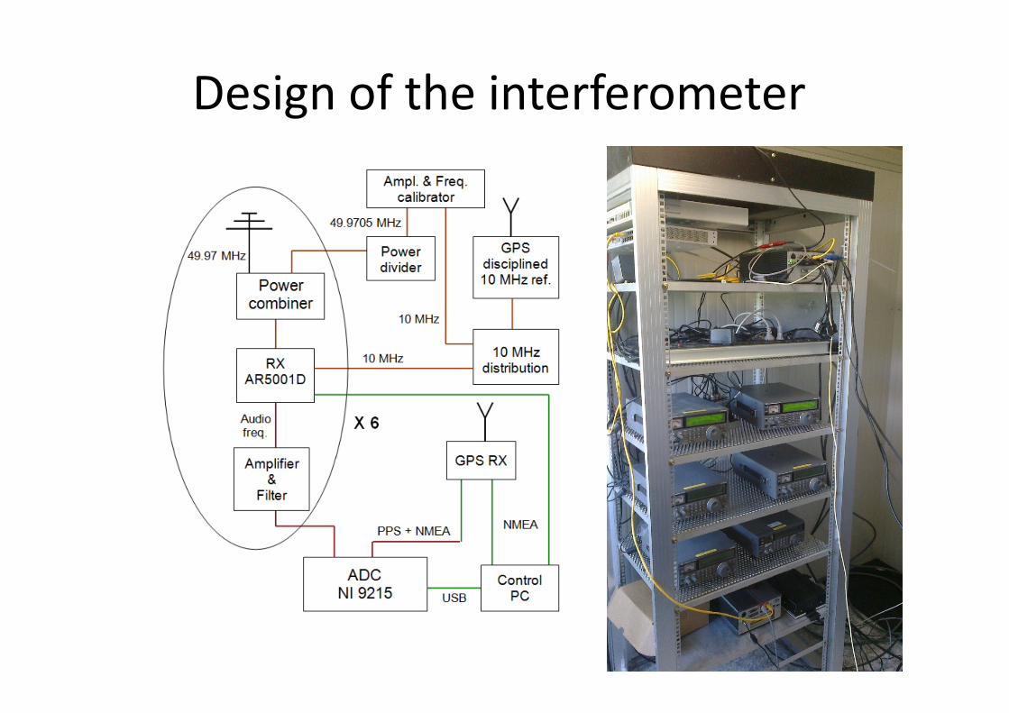
Design of the interferometer
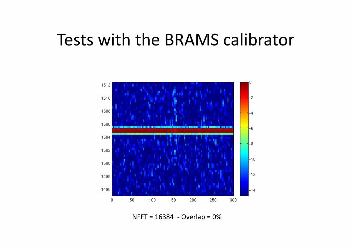
Tests with the BRAMS calibrator
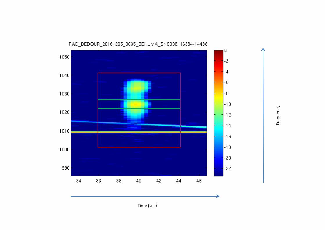
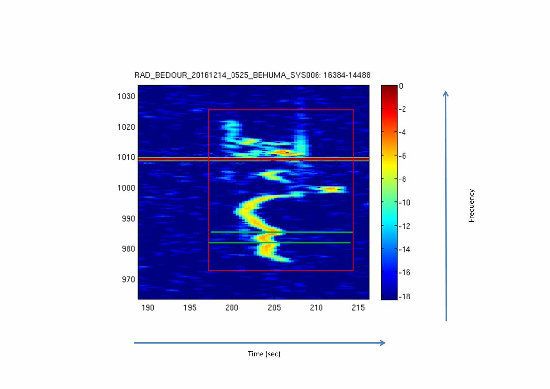
NFFT = 16384 - Overlap = 0%
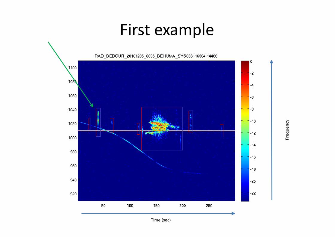
First example
Time (sec)
Fre
qu
en
cy
Time (sec)
Fre
qu
en
cy
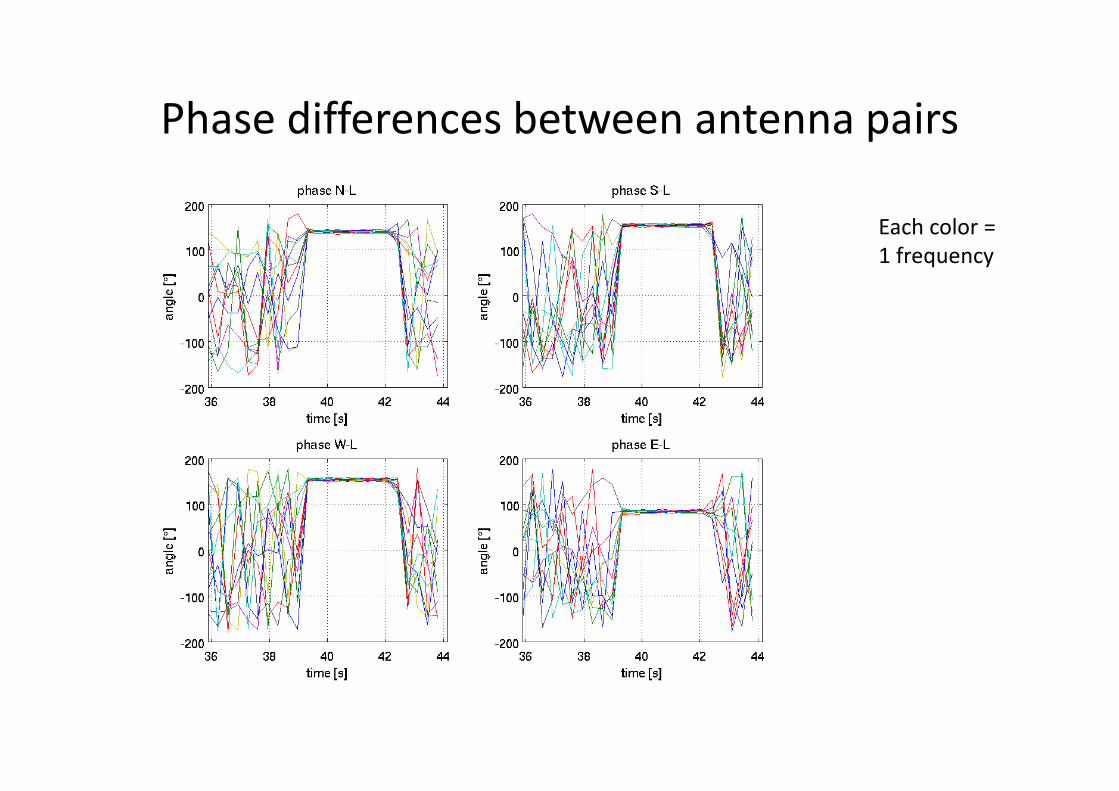
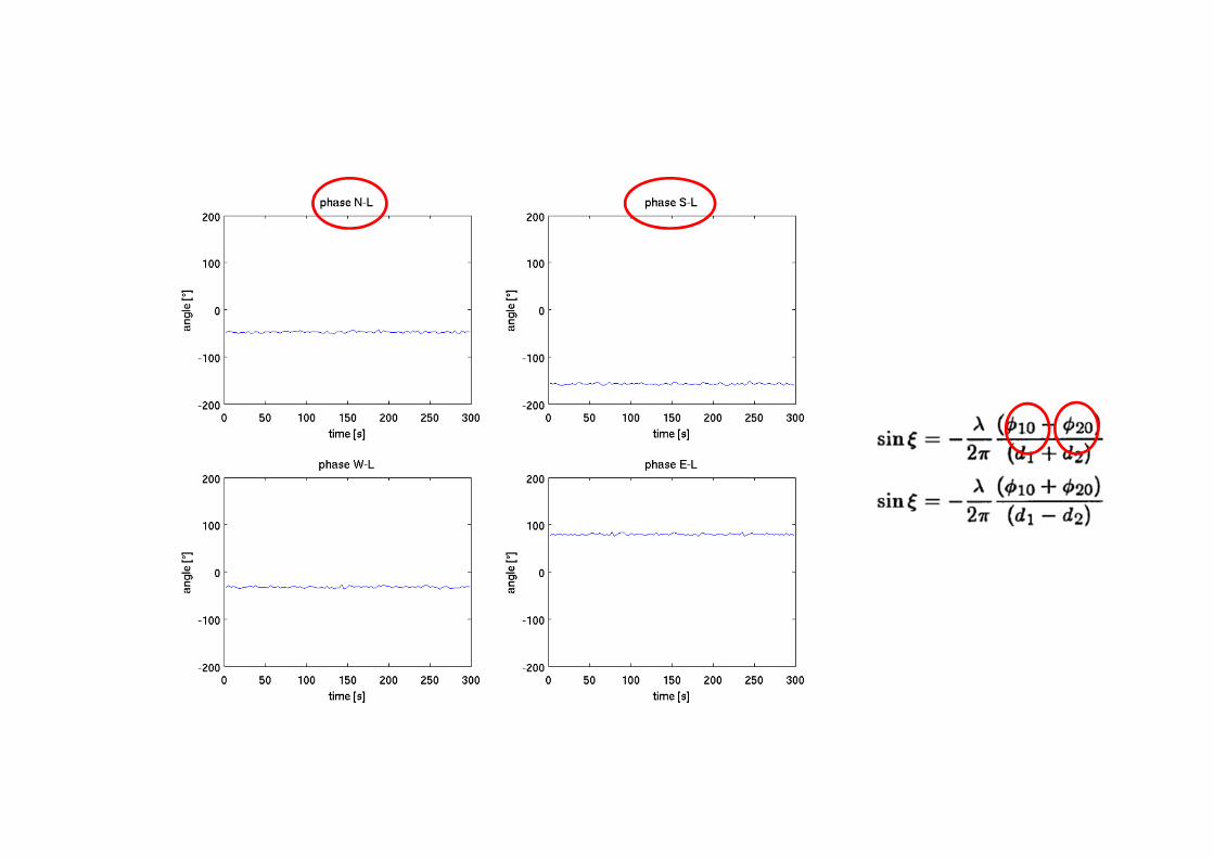
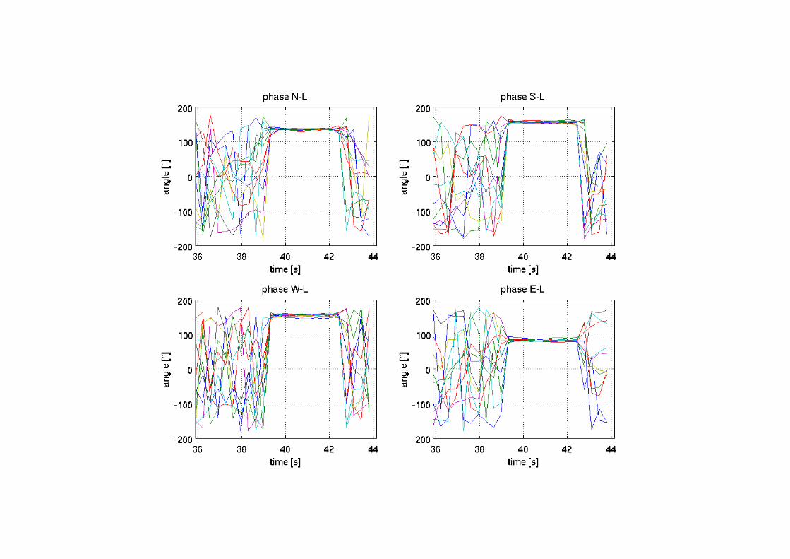
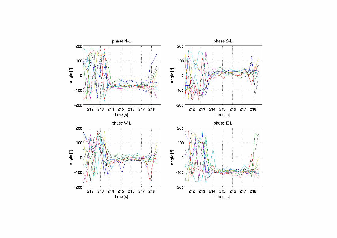
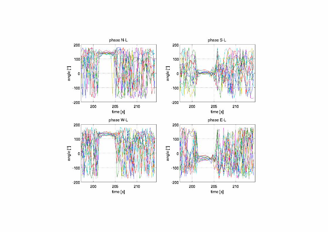
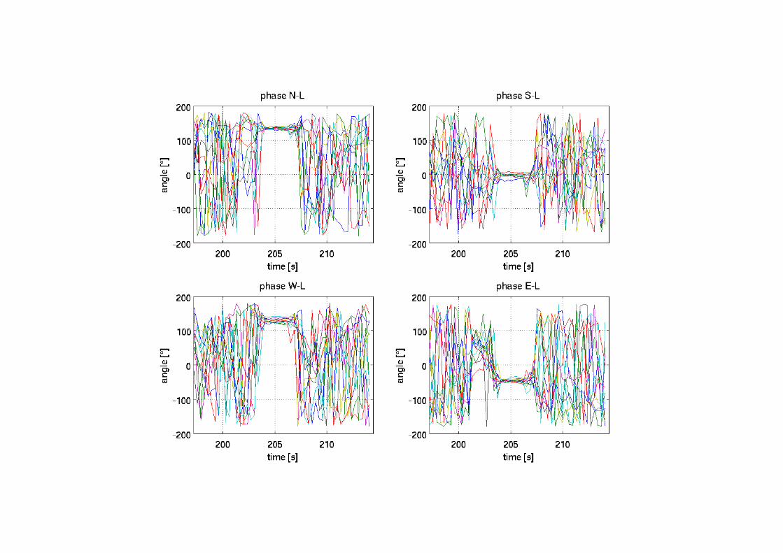
Phase differences between antenna pairs
Each color =
1 frequency
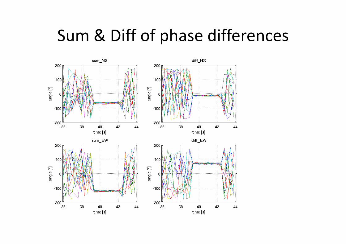
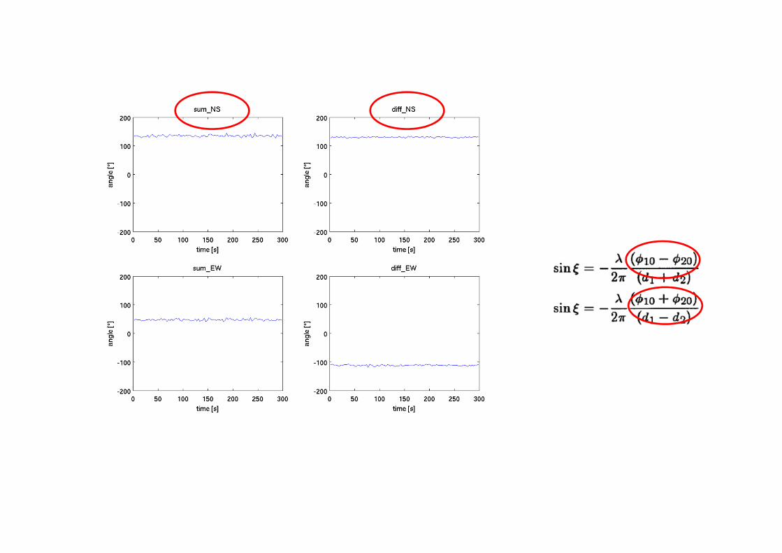
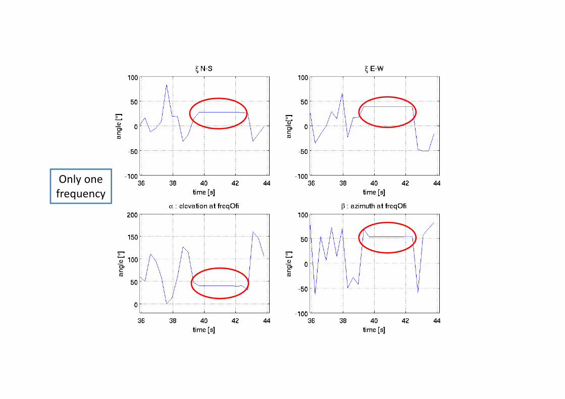
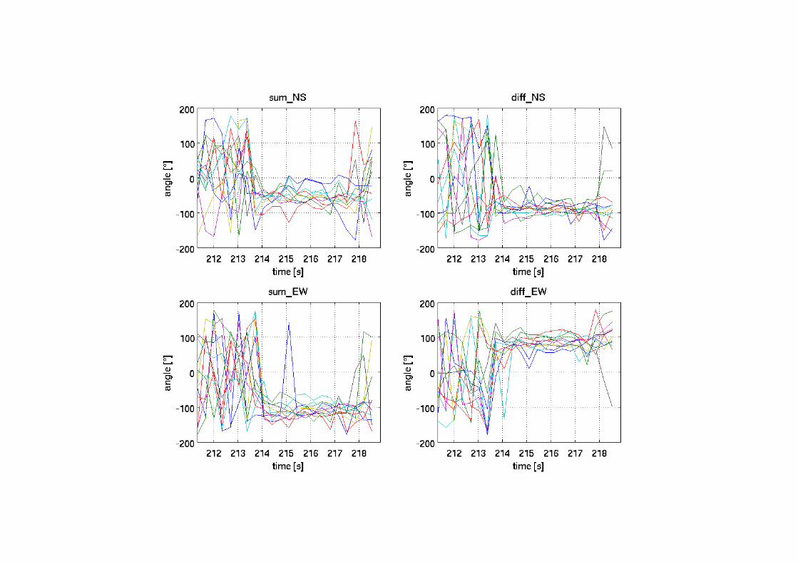
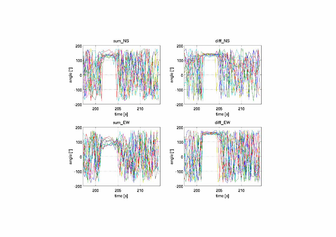
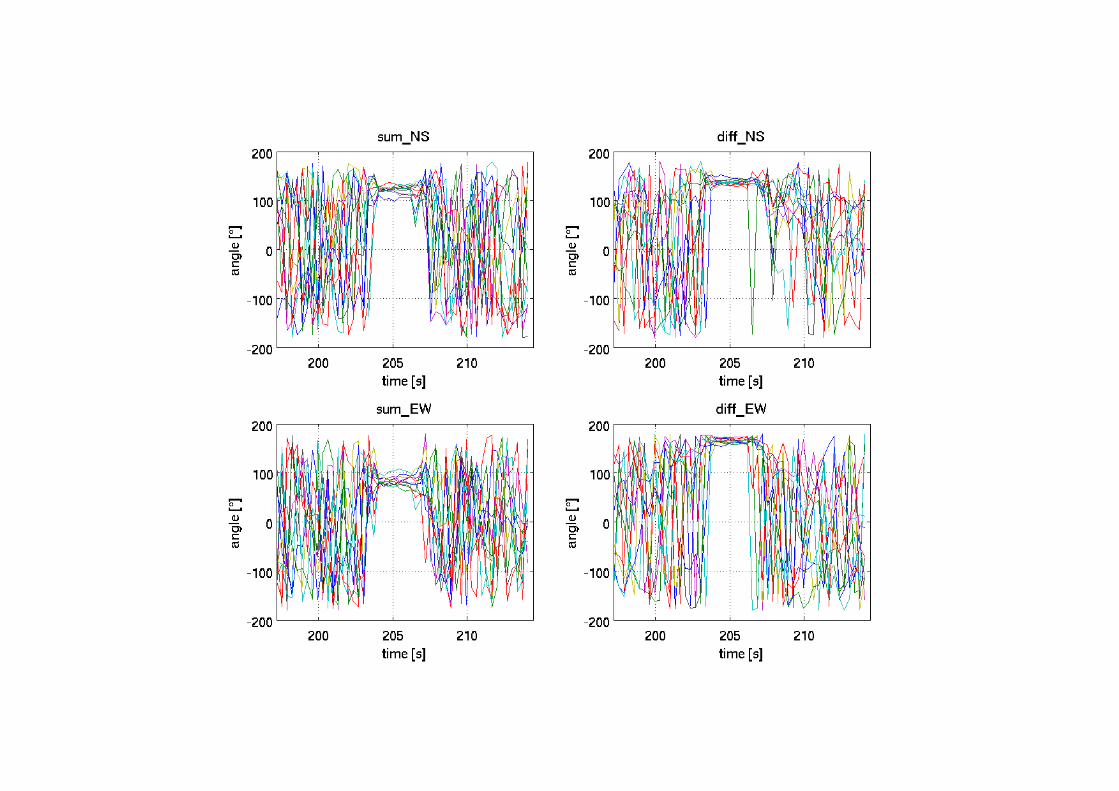
Sum & Diff of phase differences
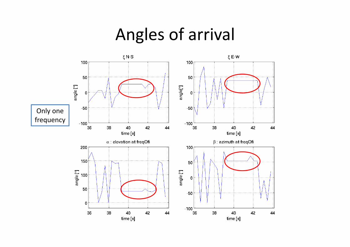
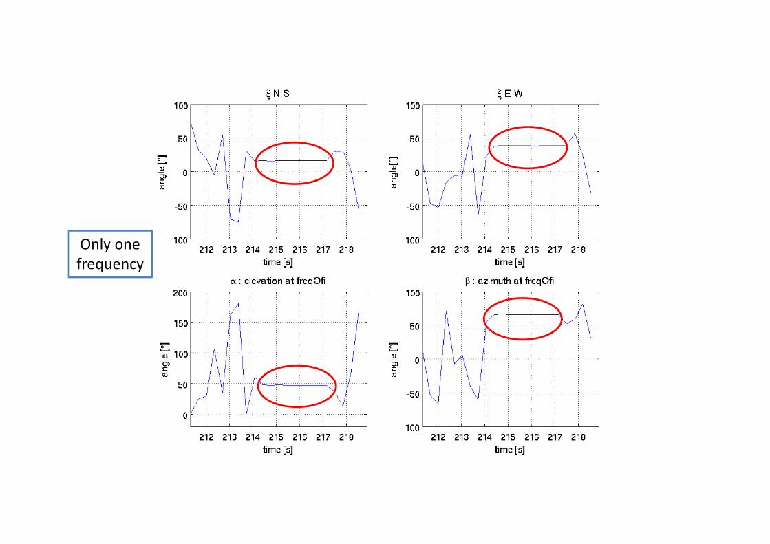
Angles of arrival
Only one
frequency
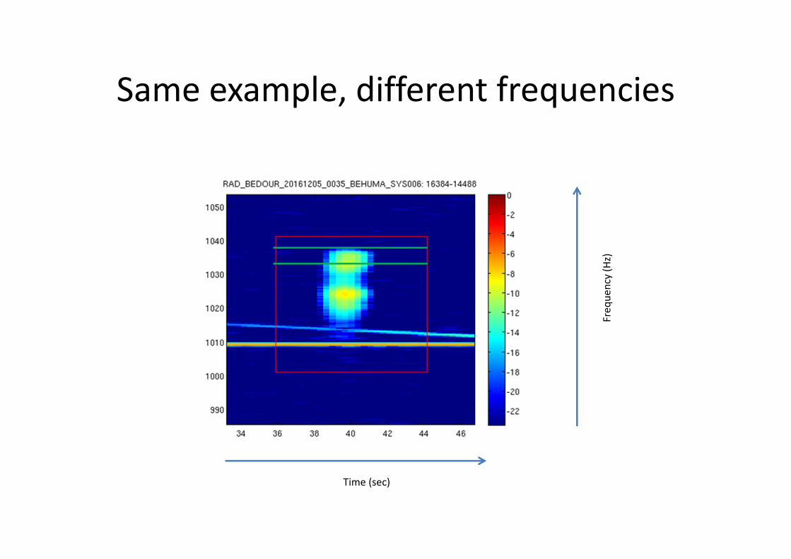
Same example, different frequencies
Time (sec)
Fre
qu
en
cy(H
z)
Only one
frequency
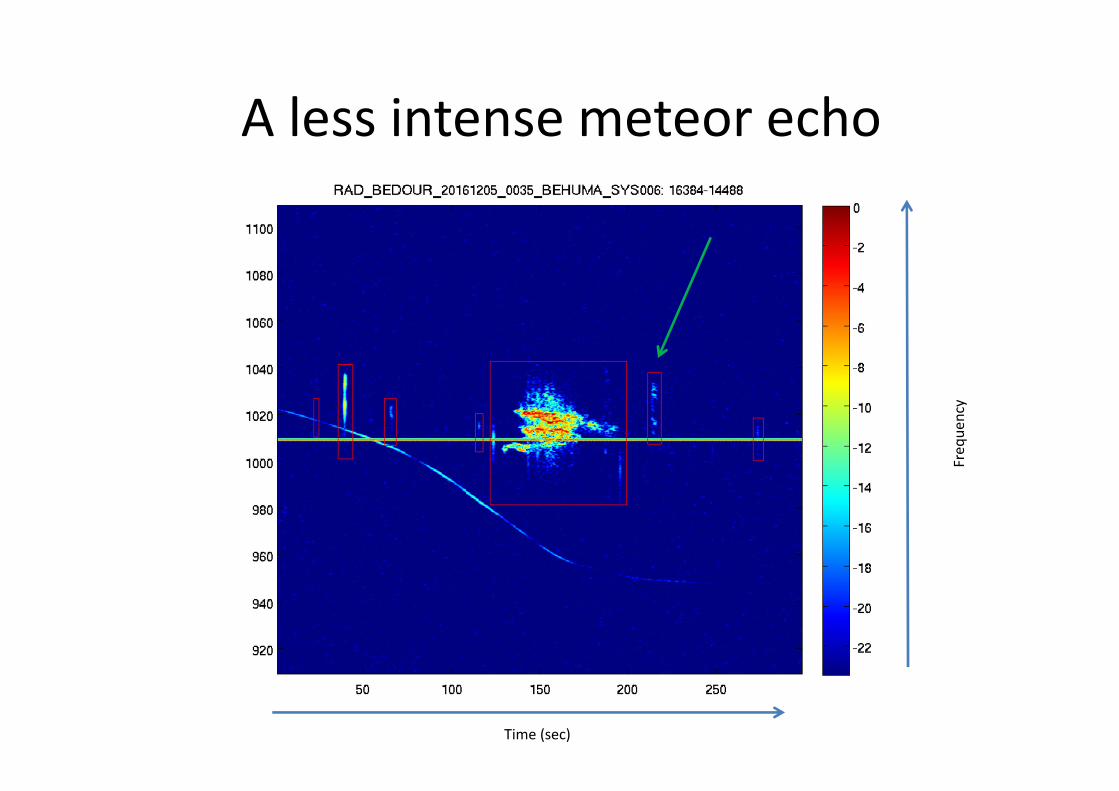
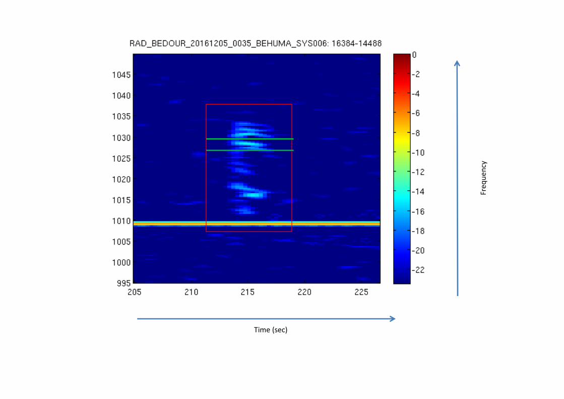
A less intense meteor echo
Time (sec)
Fre
qu
en
cy
Time (sec)
Fre
qu
en
cy
Only one
frequency
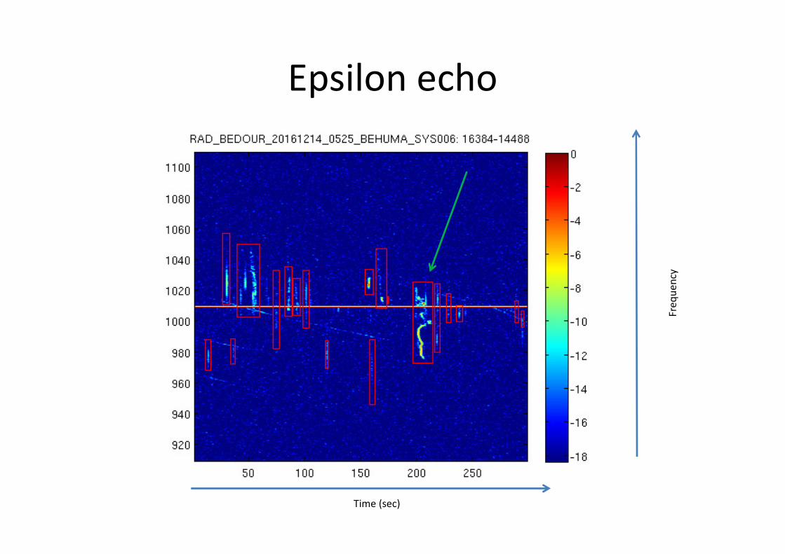
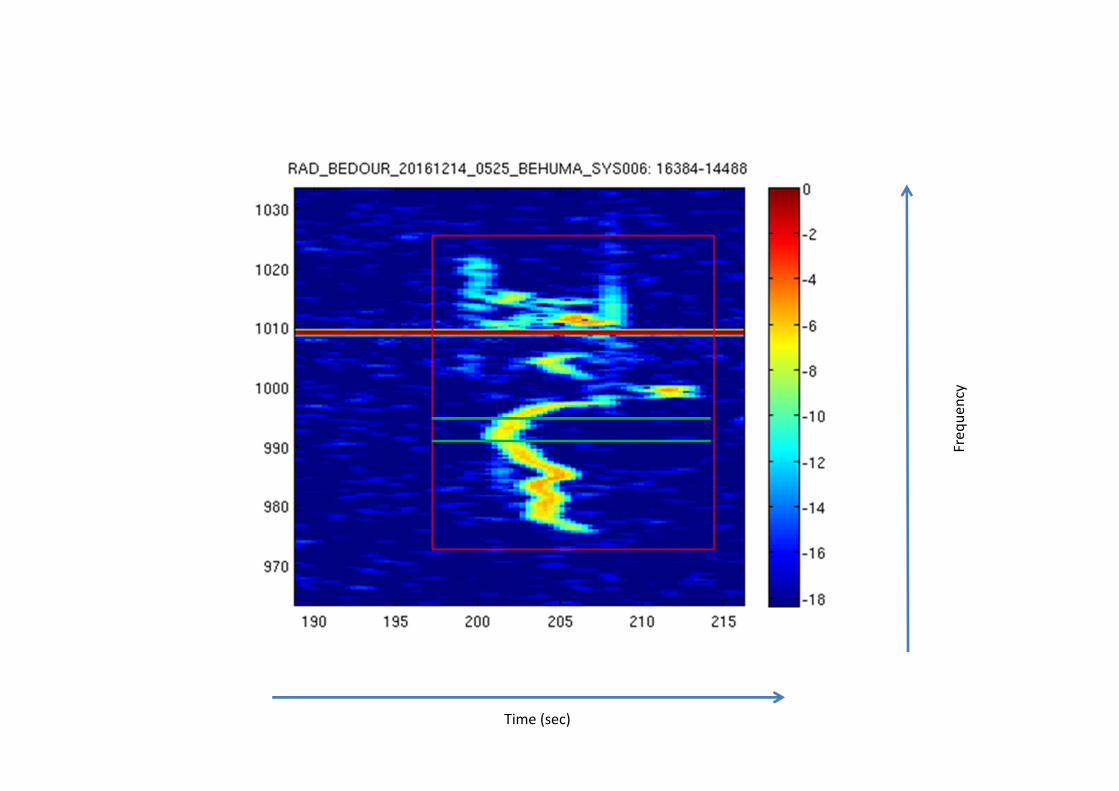
Epsilon echo
Time (sec)
Fre
qu
en
cy
Time (sec)
Fre
qu
en
cy
Time (sec)
Fre
qu
en
cy
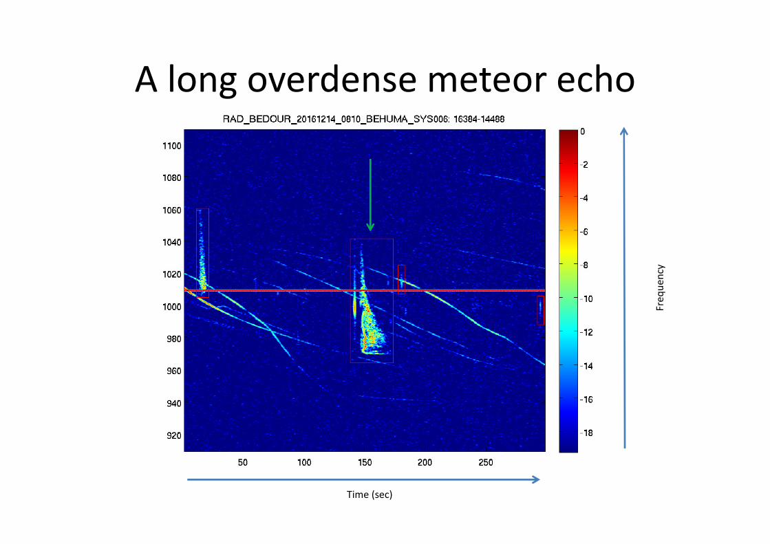
A long overdense meteor echo
Time (sec)
Fre
qu
en
cy
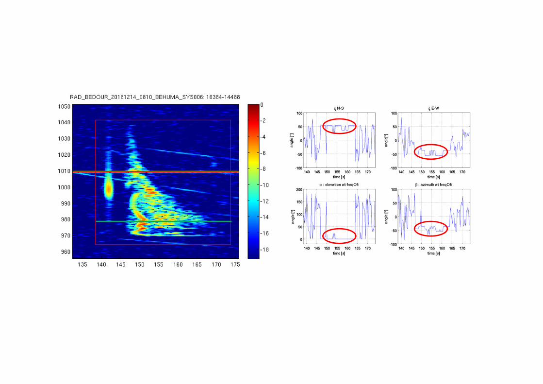
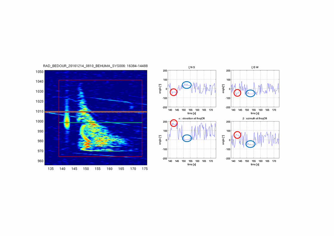
Conclusions
• Phases become coherent as soon as a meteor echo occurs. The
higher the S/N ratio, the more stable the results for the angles of
arrival
• For the fainter meteor echoes, it might be interesting to sum up the
contributions of individual frequencies present in the meteor echo to
increase the S/N ratio. This sum must be done in the complex plane
before calculating the phases. It is not so trivial …
• The directions of arrival we obtain are not calibrated at all. We find a
direction for the meteor echo but have so far no way to check that it
is correct. There are a number of systematic errors that need to be
taken into account and corrected for, e.g. the difference in length of
the cables going from the antenna to the receiver
Calibration : why?
• Different electric lengths of the cables
• Mis-alignement of the 3 antennas
• Distances between antennas ≠ 2.5λ and 2λ
• Orthogonal axes not exactly aligned along N-S and E-W
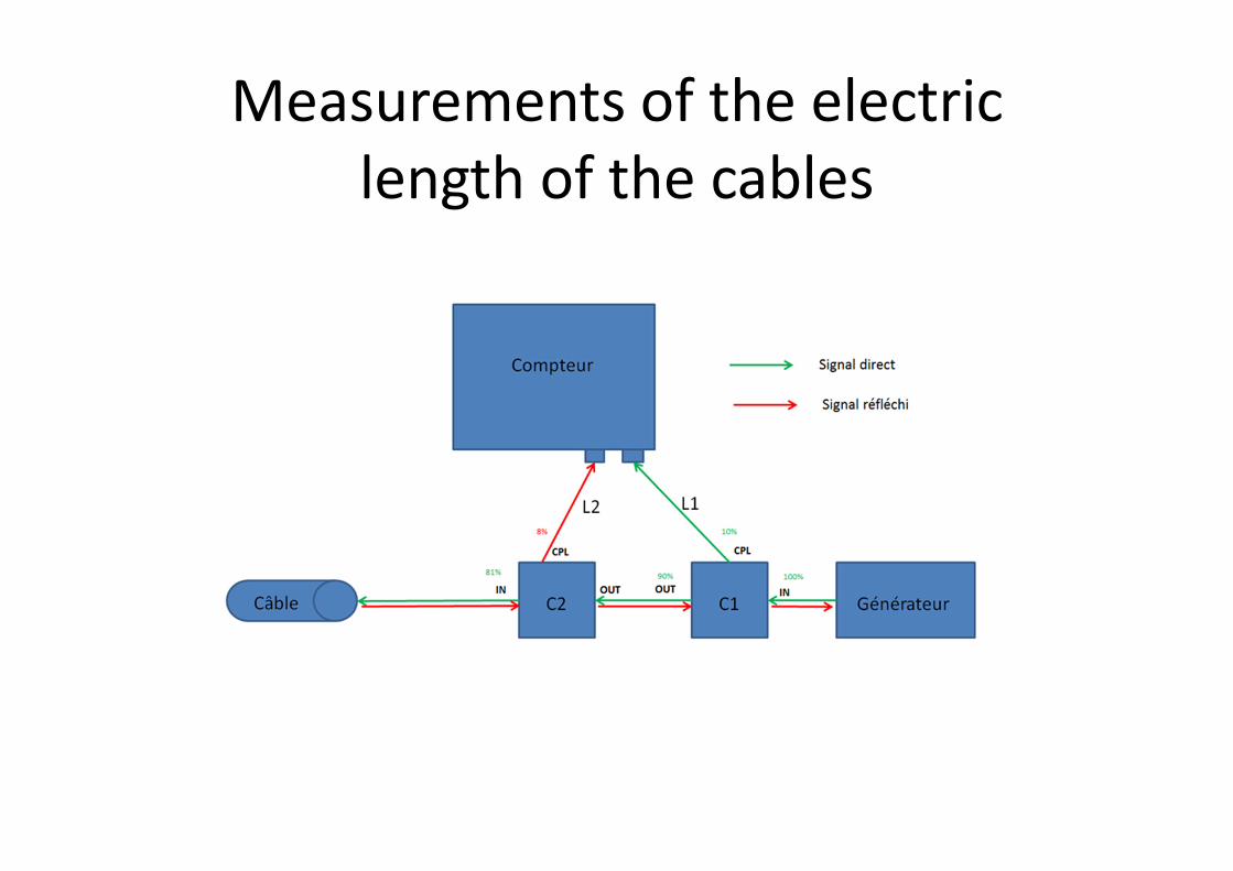
Measurements of the electric
length of the cables
Calibration : how
Can be done using one of the following options :
� Using a transmitter on a drone flying in the far-field of the interferometer
� Using the signal coming from a plane whose position can be very accurately
known
� Using data from optical cameras such as CAMS
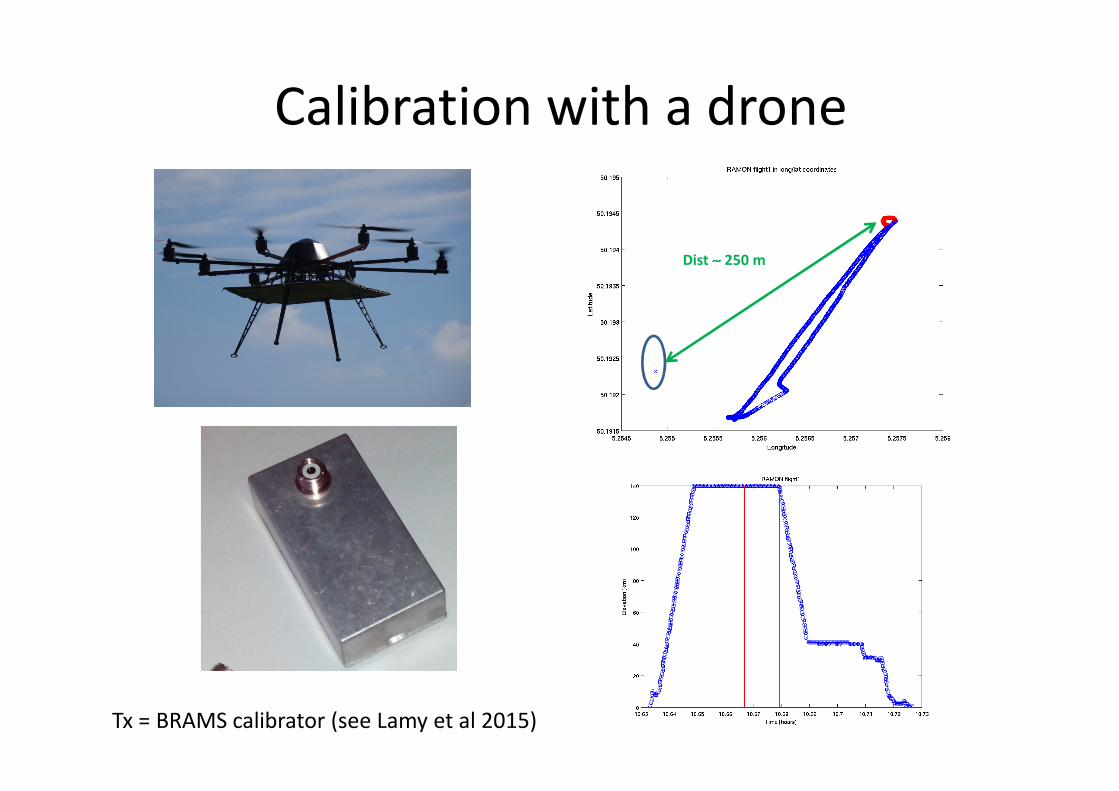
Calibration with a drone
Tx = BRAMS calibrator (see Lamy et al 2015)
Dist ∼∼∼∼ 250 m
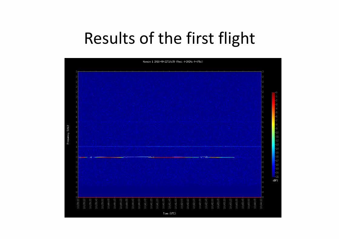
Results of the first flight

Thank you