Thermal Overcurrent Circuit Breaker 3120-F 176 ☎ 10 3120 rocker switch/circuit breaker
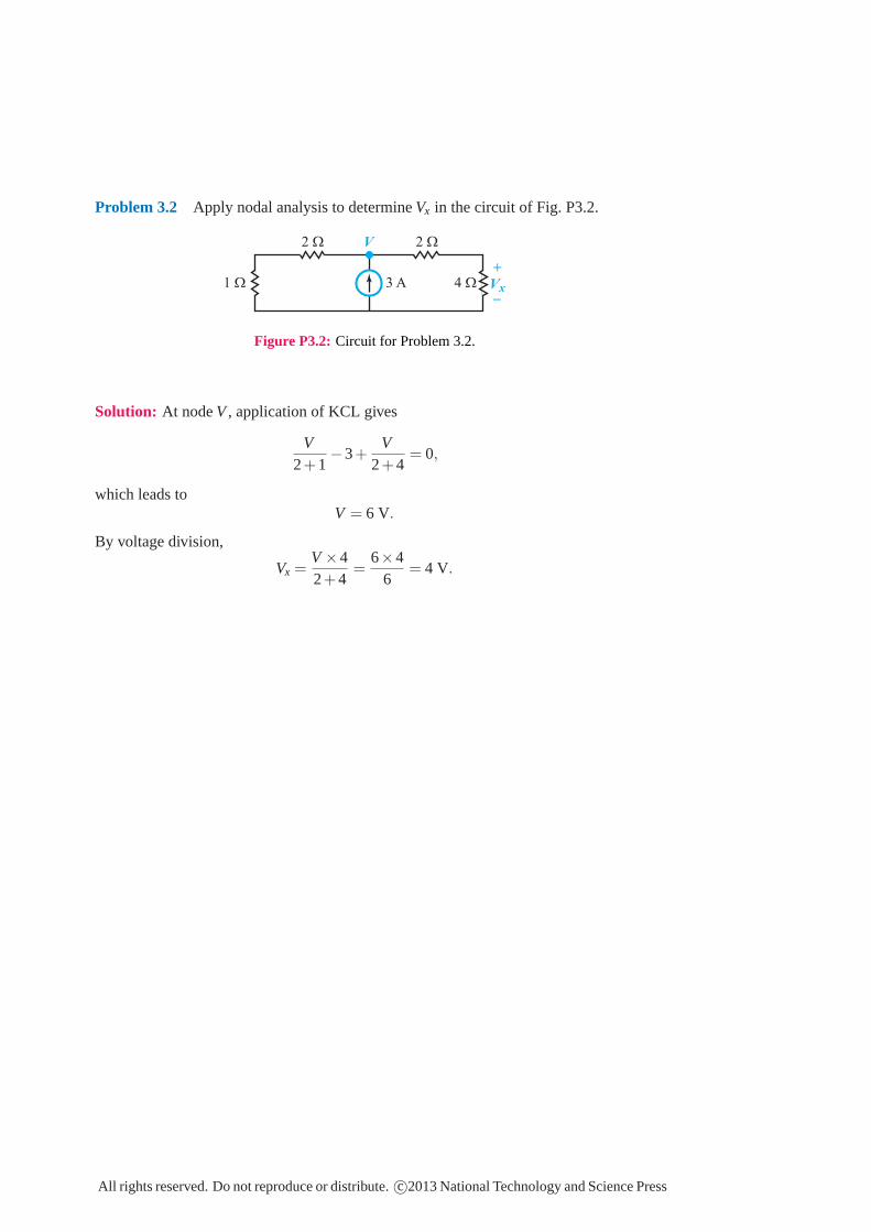
Problem 3.2 Apply nodal analysis to determine Vx in the circuit of Fig. P3.2.
1 Ω
2 Ω
4 Ω
2 Ω
3 A Vx
V
+
_
Figure P3.2: Circuit for Problem 3.2.
Solution: At node V , application of KCL gives
V2+1
−3+V
2+4= 0,
which leads toV = 6 V.
By voltage division,
Vx =V ×42+4
=6×4
6= 4 V.
All rights reserved. Do not reproduce or distribute. c©2013 National Technology and Science Press
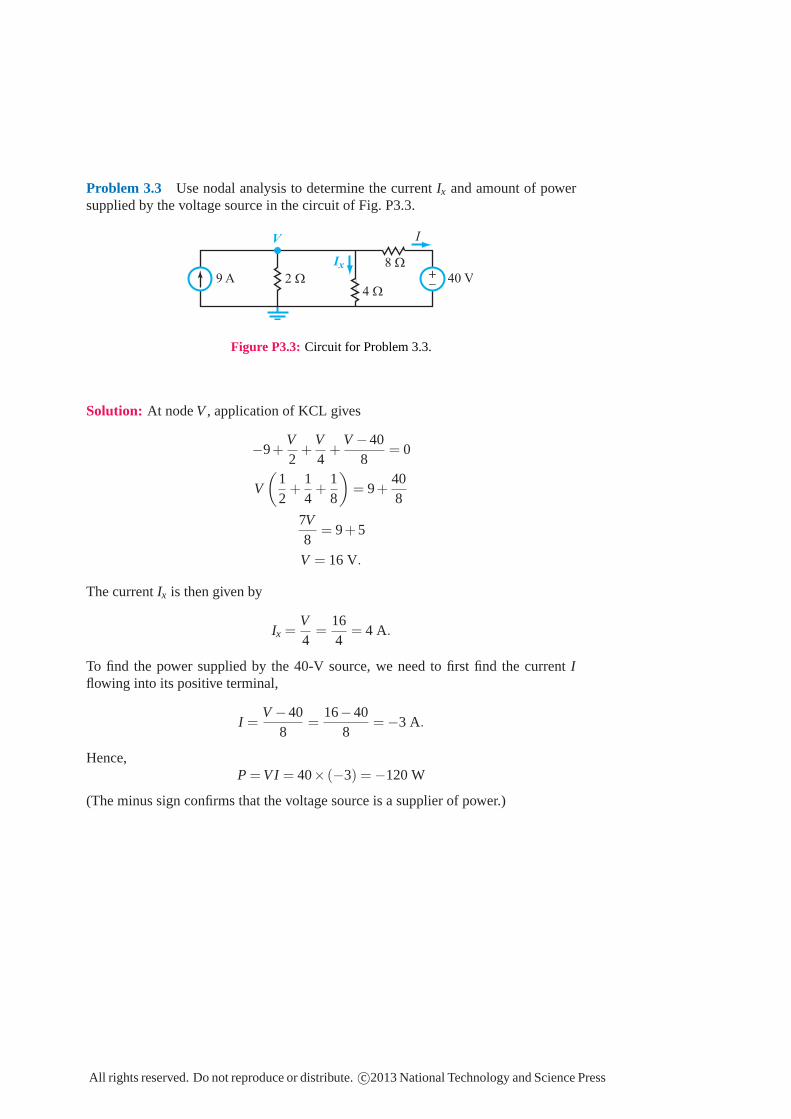
Problem 3.3 Use nodal analysis to determine the currentIx and amount of powersupplied by the voltage source in the circuit of Fig. P3.3.
2 Ω
4 Ω
8 Ω
40 V9 A
Ix
V
+_
I
Figure P3.3: Circuit for Problem 3.3.
Solution: At nodeV , application of KCL gives
−9+V2
+V4
+V −40
8= 0
V
(
12
+14
+18
)
= 9+408
7V8
= 9+5
V = 16 V.
The currentIx is then given by
Ix =V4
=164
= 4 A.
To find the power supplied by the 40-V source, we need to first find the current Iflowing into its positive terminal,
I =V −40
8=
16−408
= −3 A.
Hence,P = V I = 40× (−3) = −120 W
(The minus sign confirms that the voltage source is a supplier of power.)
All rights reserved. Do not reproduce or distribute.c©2013 National Technology and Science Press
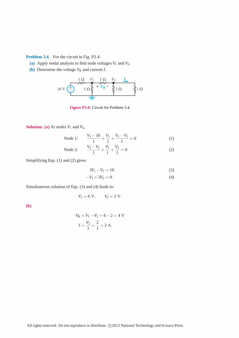
Problem 3.4 For the circuit in Fig. P3.4:
(a) Apply nodal analysis to find node voltagesV1 andV2.
(b) Determine the voltageVR and currentI.
1 Ω 1 Ω1 Ω
1 Ω 1 Ω
VR+_
16 V
V1 V2 I
+_+_
Figure P3.4: Circuit for Problem 3.4.
Solution: (a) At nodesV1 andV2,
Node 1:V1−16
1+
V1
1+
V1−V2
1= 0 (1)
Node 2:V2−V1
1+
V2
1+
V2
1= 0 (2)
Simplifying Eqs. (1) and (2) gives:
3V1−V2 = 16 (3)
−V1 +3V2 = 0. (4)
Simultaneous solution of Eqs. (3) and (4) leads to:
V1 = 6 V, V2 = 2 V.
(b)
VR = V1−V2 = 6−2 = 4 V
I =V2
1=
21
= 2 A.
All rights reserved. Do not reproduce or distribute.c©2013 National Technology and Science Press
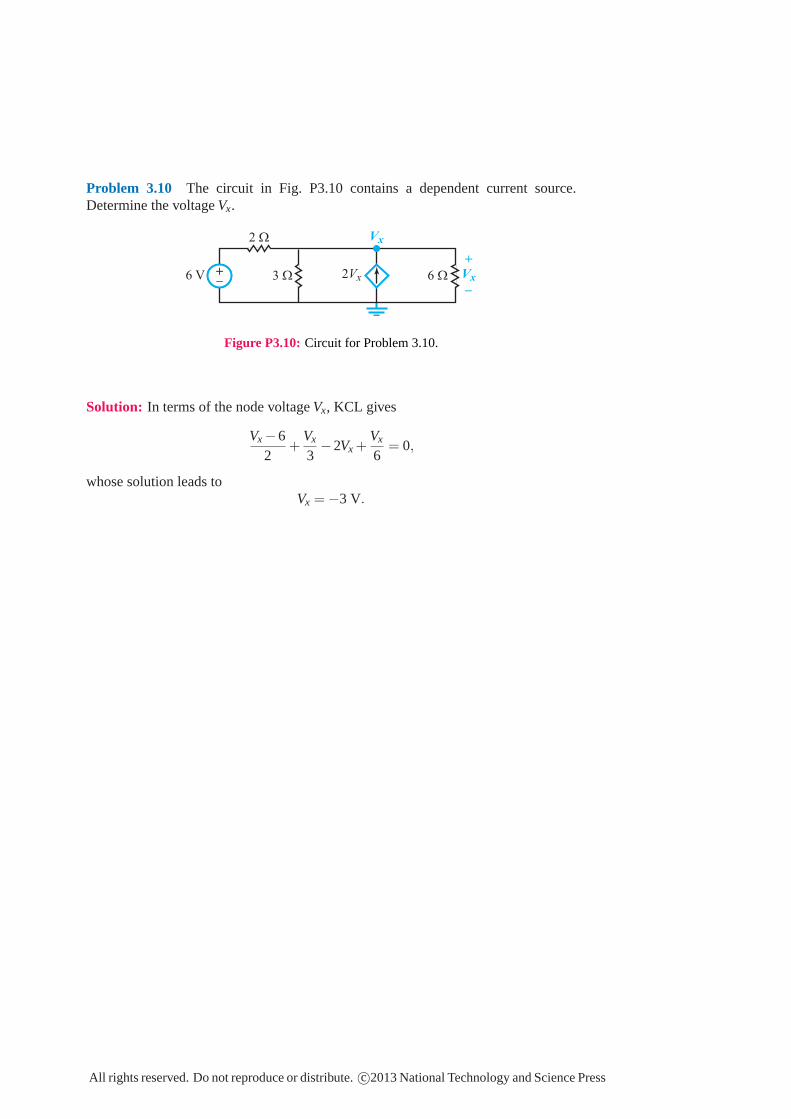
Problem 3.10 The circuit in Fig. P3.10 contains a dependent current source.Determine the voltage Vx.
2Vx3 Ω
2 Ω
6 Ω6 V Vx
Vx
+
_
+_+_
Figure P3.10: Circuit for Problem 3.10.
Solution: In terms of the node voltage Vx, KCL gives
Vx −62
+Vx
3−2Vx +
Vx
6= 0,
whose solution leads toVx = −3 V.
All rights reserved. Do not reproduce or distribute. c©2013 National Technology and Science Press
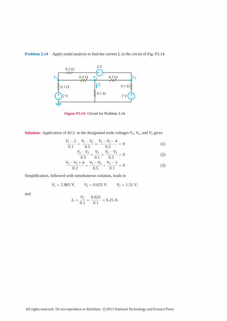
Problem 3.14 Apply nodal analysis to find the currentIx in the circuit of Fig. P3.14.
0.1 Ω
0.1 Ω
0.5 Ω0.5 Ω
0.2 Ω
0.1 Ω
3 V2 V
4 V
Ix
+_
+_
+_
+_
+ _
V1 V2 V3
Figure P3.14: Circuit for Problem 3.14.
Solution: Application of KCL to the designated node voltagesV1, V2, andV3 gives
V1−20.1
+V1−V2
0.5+
V1−V3−40.2
= 0 (1)
V2−V1
0.5+
V2
0.1+
V2−V3
0.5= 0 (2)
V3−V1 +40.2
+V3−V2
0.5+
V3−30.1
= 0 (3)
Simplification, followed with simultaneous solution, leads to
V1 = 2.865 V, V2 = 0.625 V, V3 = 1.51 V,
and
Ix =V2
0.1=
0.6250.1
= 6.25 A.
All rights reserved. Do not reproduce or distribute.c©2013 National Technology and Science Press
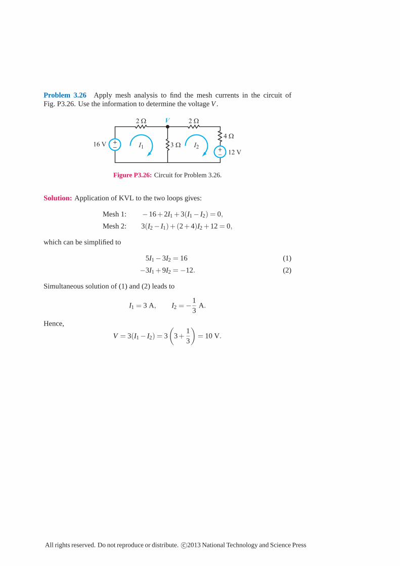
Problem 3.26 Apply mesh analysis to find the mesh currents in the circuit ofFig. P3.26. Use the information to determine the voltageV .
2 Ω
4 Ω
3 Ω
2 Ω
I1 I216 V
12 V
V
+_ +
_
Figure P3.26: Circuit for Problem 3.26.
Solution: Application of KVL to the two loops gives:
Mesh 1: −16+2I1 +3(I1− I2) = 0,
Mesh 2: 3(I2− I1)+(2+4)I2 +12= 0,
which can be simplified to
5I1−3I2 = 16 (1)
−3I1 +9I2 = −12. (2)
Simultaneous solution of (1) and (2) leads to
I1 = 3 A, I2 = −13
A.
Hence,
V = 3(I1− I2) = 3
(
3+13
)
= 10 V.
All rights reserved. Do not reproduce or distribute.c©2013 National Technology and Science Press
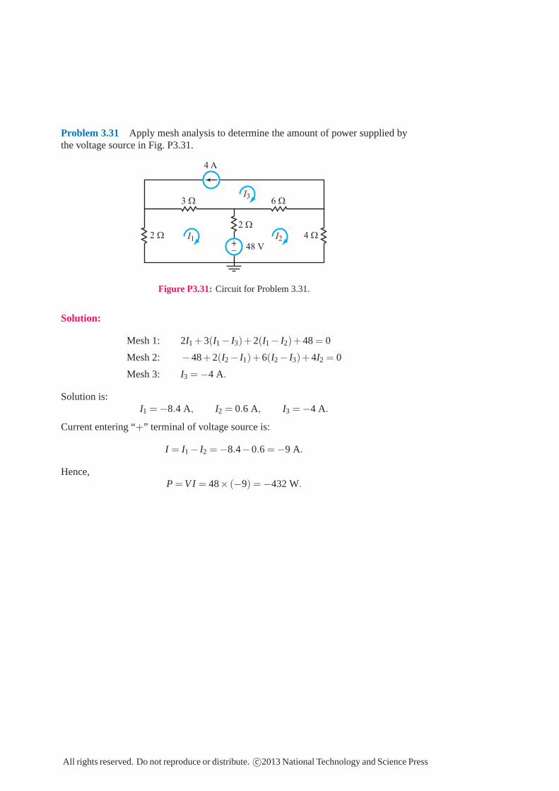
Problem 3.31 Apply mesh analysis to determine the amount of power supplied bythe voltage source in Fig. P3.31.
3 Ω 6 Ω
2 Ω
2 Ω 4 Ω
4 A
48 V
+_
I1 I2
I3
Figure P3.31: Circuit for Problem 3.31.
Solution:
Mesh 1: 2I1 +3(I1− I3)+2(I1− I2)+48= 0
Mesh 2: −48+2(I2− I1)+6(I2− I3)+4I2 = 0
Mesh 3: I3 = −4 A.
Solution is:I1 = −8.4 A, I2 = 0.6 A, I3 = −4 A.
Current entering “+” terminal of voltage source is:
I = I1− I2 = −8.4−0.6 = −9 A.
Hence,P = V I = 48× (−9) = −432 W.
All rights reserved. Do not reproduce or distribute.c©2013 National Technology and Science Press
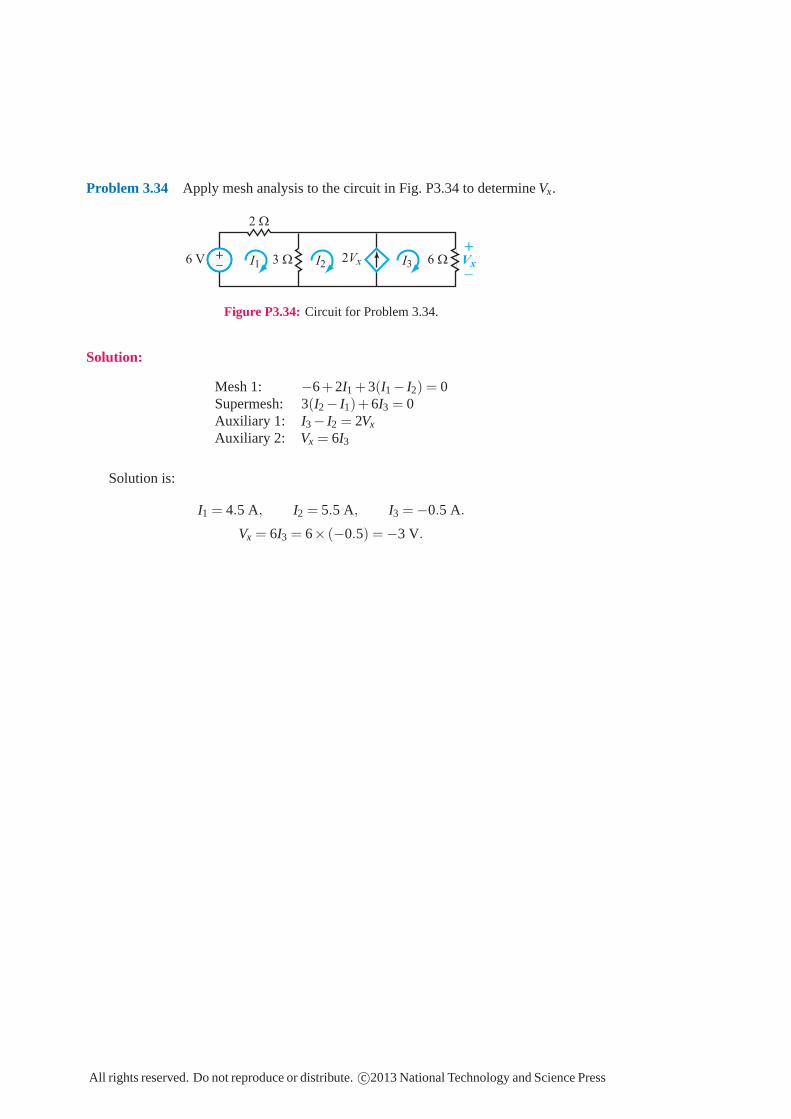
Problem 3.34 Apply mesh analysis to the circuit in Fig. P3.34 to determine Vx.
2Vx3 Ω
2 Ω
6 Ω6 V
+_+_ I1 I2 I3
+
_Vx
+_
Figure P3.34: Circuit for Problem 3.34.
Solution:
Mesh 1: −6+2I1 +3(I1 − I2) = 0Supermesh: 3(I2 − I1)+6I3 = 0Auxiliary 1: I3 − I2 = 2Vx
Auxiliary 2: Vx = 6I3
Solution is:
I1 = 4.5 A, I2 = 5.5 A, I3 = −0.5 A.
Vx = 6I3 = 6× (−0.5) = −3 V.
All rights reserved. Do not reproduce or distribute. c©2013 National Technology and Science Press
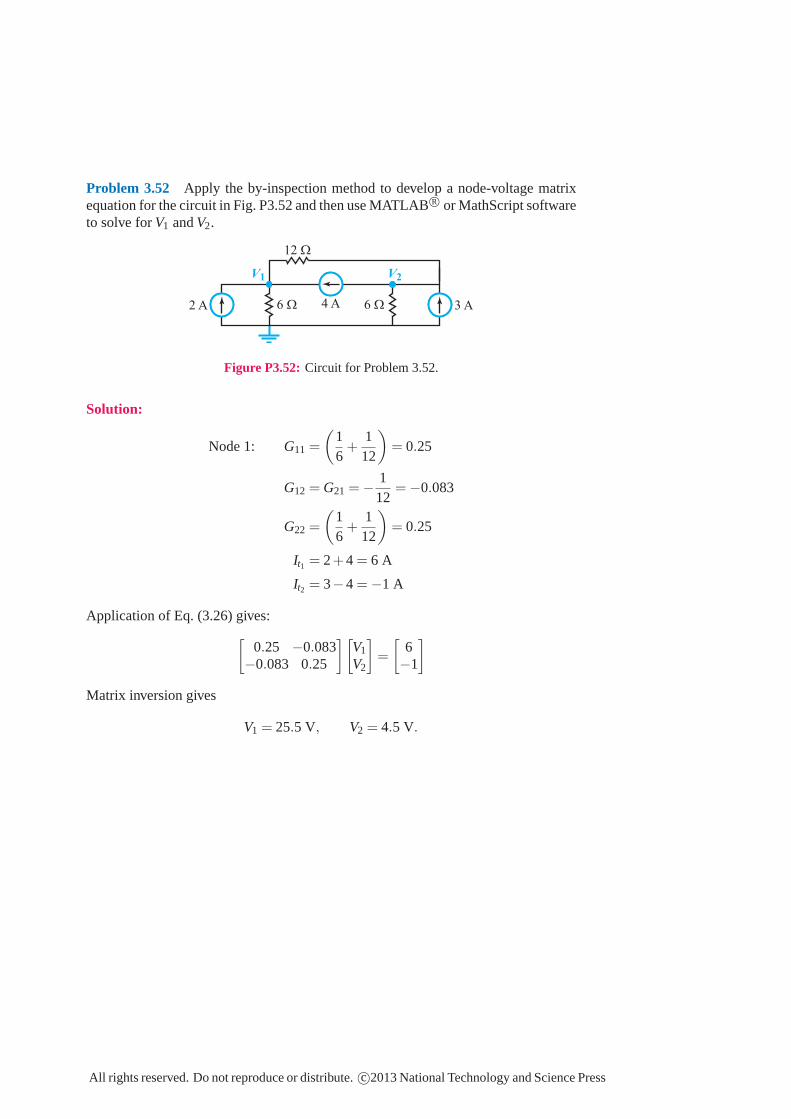
Problem 3.52 Apply the by-inspection method to develop a node-voltage matrixequation for the circuit in Fig. P3.52 and then use MATLAB R© or MathScript softwareto solve for V1 and V2.
6 Ω
12 Ω
6 Ω 3 A4 A2 A
V1 V2
Figure P3.52: Circuit for Problem 3.52.
Solution:
Node 1: G11 =
(
16
+1
12
)
= 0.25
G12 = G21 = −112
= −0.083
G22 =
(
16
+1
12
)
= 0.25
It1 = 2+4 = 6 A
It2 = 3−4 = −1 A
Application of Eq. (3.26) gives:[
0.25 −0.083−0.083 0.25
][
V1
V2
]
=
[
6−1
]
Matrix inversion gives
V1 = 25.5 V, V2 = 4.5 V.
All rights reserved. Do not reproduce or distribute. c©2013 National Technology and Science Press
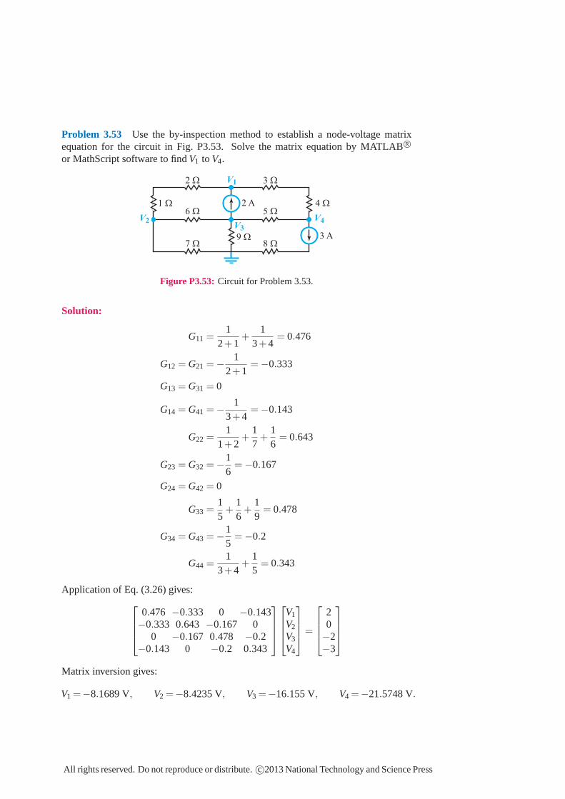
Problem 3.53 Use the by-inspection method to establish a node-voltage matrixequation for the circuit in Fig. P3.53. Solve the matrix equation by MATLABR©
or MathScript software to findV1 to V4.
8 Ω9 Ω
5 Ω
3 Ω2 Ω
6 Ω1 Ω 4 Ω
7 Ω3 A
2 A
V1
V4V2V3
Figure P3.53: Circuit for Problem 3.53.
Solution:
G11 =1
2+1+
13+4
= 0.476
G12 = G21 = −1
2+1= −0.333
G13 = G31 = 0
G14 = G41 = −1
3+4= −0.143
G22 =1
1+2+
17
+16
= 0.643
G23 = G32 = −16
= −0.167
G24 = G42 = 0
G33 =15
+16
+19
= 0.478
G34 = G43 = −15
= −0.2
G44 =1
3+4+
15
= 0.343
Application of Eq. (3.26) gives:
0.476 −0.333 0 −0.143−0.333 0.643 −0.167 0
0 −0.167 0.478 −0.2−0.143 0 −0.2 0.343
V1
V2
V3
V4
=
20−2−3
Matrix inversion gives:
V1 =−8.1689 V, V2 =−8.4235 V, V3 =−16.155 V, V4 =−21.5748 V.
All rights reserved. Do not reproduce or distribute.c©2013 National Technology and Science Press
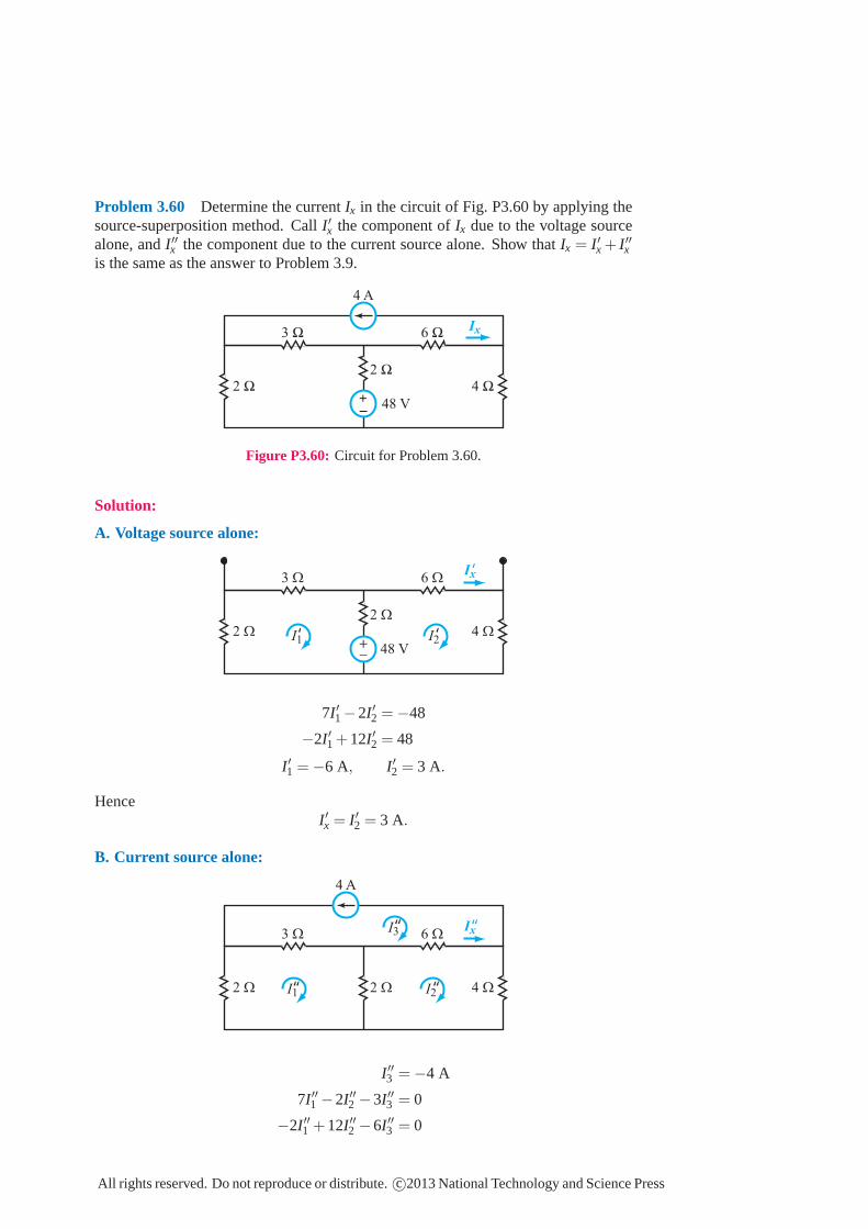
Problem 3.60 Determine the current Ix in the circuit of Fig. P3.60 by applying thesource-superposition method. Call I′x the component of Ix due to the voltage sourcealone, and I′′x the component due to the current source alone. Show that Ix = I′x + I′′xis the same as the answer to Problem 3.9.
3 Ω 6 Ω
2 Ω
2 Ω 4 Ω
4 A
48 V
+_
Ix
Figure P3.60: Circuit for Problem 3.60.
Solution:
A. Voltage source alone:
3 Ω 6 Ω
2 Ω
2 Ω 4 Ω
48 V
Ix
+_
‘
I1 I2‘ ‘
7I′1 −2I′2 = −48
−2I′1 +12I′2 = 48
I′1 = −6 A, I′2 = 3 A.
HenceI′x = I′2 = 3 A.
B. Current source alone:
3 Ω 6 Ω
2 Ω2 Ω 4 Ω
4 A
Ix‘‘‘‘
‘‘I1 ‘‘I2
I3
I′′3 = −4 A
7I′′1 −2I′′2 −3I′′3 = 0
−2I′′1 +12I′′2 −6I′′3 = 0
All rights reserved. Do not reproduce or distribute. c©2013 National Technology and Science Press
Hence,
I′′1 = −2.4 A, I′′2 = −2.4 A.
I′′x = I′′2 − I′′3 = −2.4+4 = 1.6 A.
Ix = I′x + I′′x = 3+1.6 = 4.6 A.
All rights reserved. Do not reproduce or distribute. c©2013 National Technology and Science Press
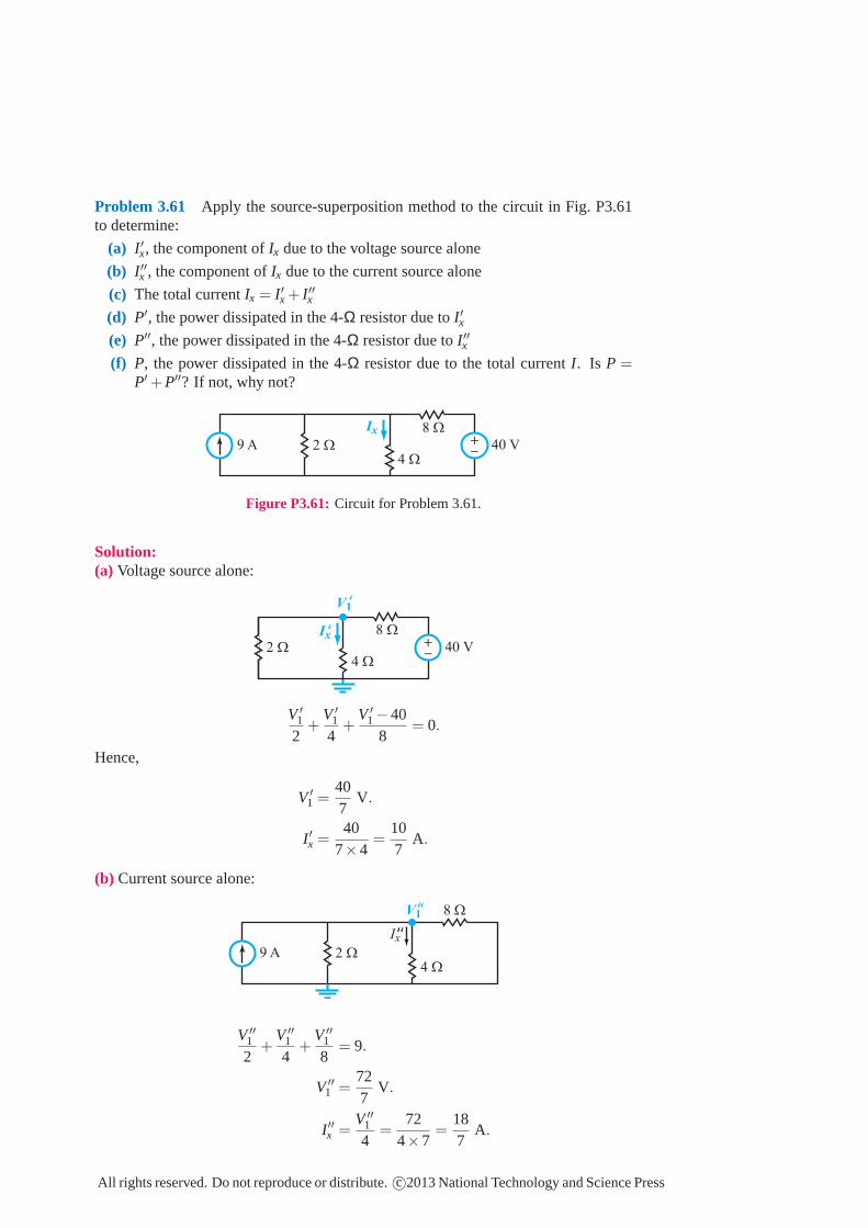
Problem 3.61 Apply the source-superposition method to the circuit in Fig. P3.61to determine:
(a) I′x, the component of Ix due to the voltage source alone
(b) I′′x , the component of Ix due to the current source alone
(c) The total current Ix = I′x + I′′x(d) P′, the power dissipated in the 4-Ω resistor due to I′x(e) P′′, the power dissipated in the 4-Ω resistor due to I′′x(f) P, the power dissipated in the 4-Ω resistor due to the total current I. Is P =
P′+P′′? If not, why not?
2 Ω
4 Ω
8 Ω
40 V9 A
Ix +_
Figure P3.61: Circuit for Problem 3.61.
Solution:(a) Voltage source alone:
2 Ω
4 Ω
8 Ω
40 V
+_
V1
Ix‘
‘
V ′1
2+
V ′1
4+
V ′1 −40
8= 0.
Hence,
V ′1 =
407
V.
I′x =40
7×4=
107
A.
(b) Current source alone:
2 Ω
4 Ω
8 Ω
9 A
Ix
V1
‘‘
‘‘
V ′′1
2+
V ′′1
4+
V ′′1
8= 9.
V ′′1 =
727
V.
I′′x =V ′′
1
4=
724×7
=187
A.
All rights reserved. Do not reproduce or distribute. c©2013 National Technology and Science Press
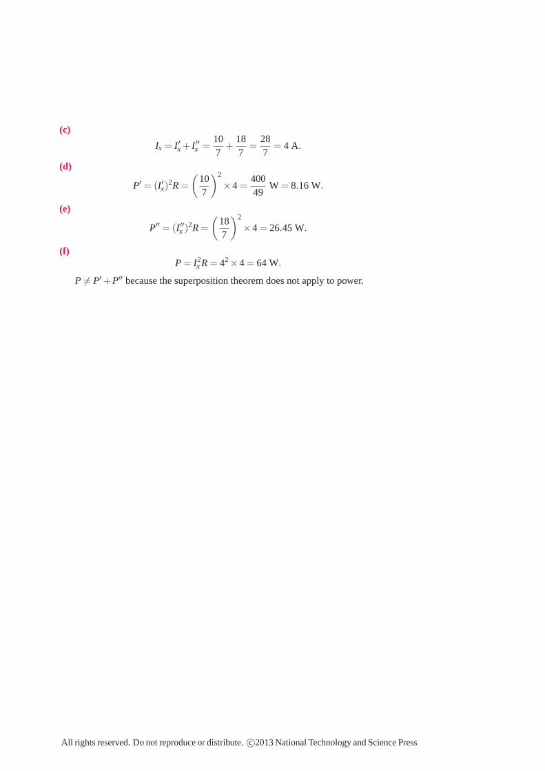
(c)
Ix = I′x + I′′x =107
+187
=287
= 4 A.
(d)
P′= (I′x)
2R =
(
107
)2
×4 =40049
W = 8.16 W.
(e)
P′′= (I′′x )
2R =
(
187
)2
×4 = 26.45 W.
(f)P = I2
x R = 42 ×4 = 64 W.
P 6= P′+P′′ because the superposition theorem does not apply to power.
All rights reserved. Do not reproduce or distribute. c©2013 National Technology and Science Press
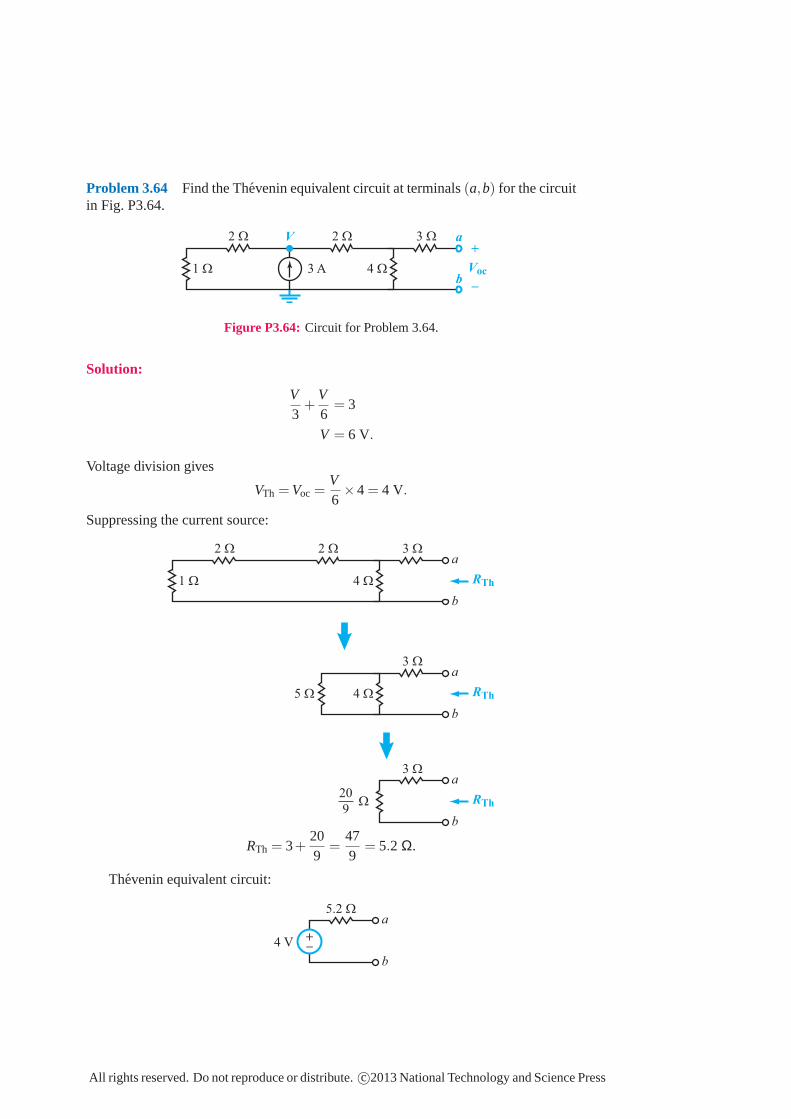
Problem 3.64 Find the Thevenin equivalent circuit at terminals(a,b) for the circuitin Fig. P3.64.
1 Ω
2 Ω 3 Ω
4 Ω
2 Ω
3 A
a
b
Voc
V
+
_
Figure P3.64: Circuit for Problem 3.64.
Solution:
V3
+V6
= 3
V = 6 V.
Voltage division gives
VTh = Voc =V6×4 = 4 V.
Suppressing the current source:
1 Ω
2 Ω 3 Ω
4 Ω
2 Ωa
b
RTh
RTh
RTh
5 Ω
3 Ω
4 Ω
a
b
3 Ω
Ω
a
b
20
9
RTh = 3+209
=479
= 5.2 Ω.
Thevenin equivalent circuit:
5.2 Ωa
b
4 V
+_
All rights reserved. Do not reproduce or distribute.c©2013 National Technology and Science Press
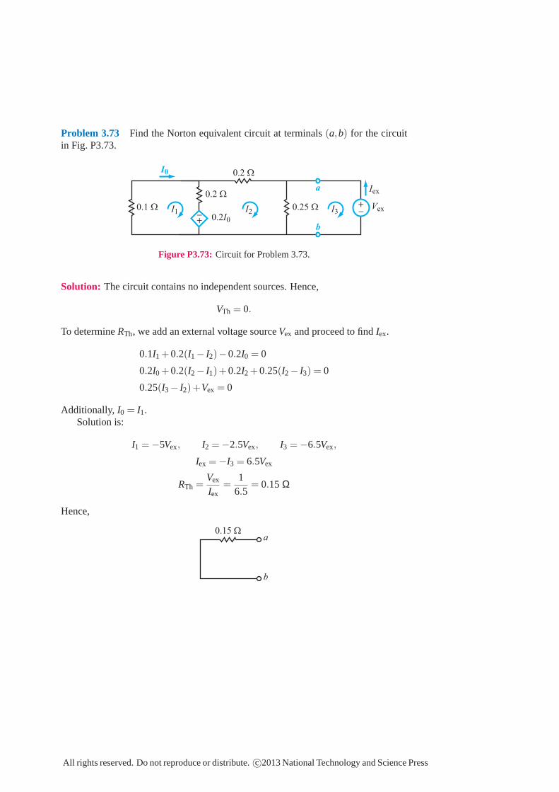
Problem 3.73 Find the Norton equivalent circuit at terminals(a,b) for the circuitin Fig. P3.73.
0.2 Ω
0.2 Ω
0.1 Ω 0.25 Ω
a
b
I0
0.2I0
Iex
Vex
+_I1 I2 I3
+_
Figure P3.73: Circuit for Problem 3.73.
Solution: The circuit contains no independent sources. Hence,
VTh = 0.
To determineRTh, we add an external voltage sourceVex and proceed to findIex.
0.1I1 +0.2(I1− I2)−0.2I0 = 0
0.2I0 +0.2(I2− I1)+0.2I2 +0.25(I2− I3) = 0
0.25(I3− I2)+Vex = 0
Additionally, I0 = I1.Solution is:
I1 = −5Vex, I2 = −2.5Vex, I3 = −6.5Vex,
Iex = −I3 = 6.5Vex
RTh =Vex
Iex=
16.5
= 0.15 Ω
Hence,
a
b
0.15 Ω
All rights reserved. Do not reproduce or distribute.c©2013 National Technology and Science Press
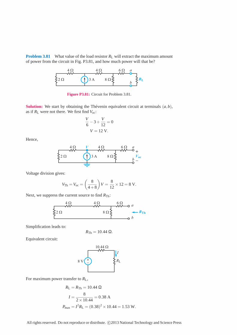
Problem 3.81 What value of the load resistorRL will extract the maximum amountof power from the circuit in Fig. P3.81, and how much power will that be?
2 Ω
4 Ω 6 Ω
8 Ω
4 Ω
3 A RL
a
b
Figure P3.81: Circuit for Problem 3.81.
Solution: We start by obtaining the Thevenin equivalent circuit at terminals(a,b),as if RL were not there. We first findVoc:
V6−3+
V12
= 0
V = 12 V.
Hence,
2 Ω
4 Ω 6 Ω
8 Ω
4 Ω
3 A
a
bVoc
V
+
_
Voltage division gives:
VTh = Voc =
(
84+8
)
V =812
×12= 8 V.
Next, we suppress the current source to findRTh:
2 Ω
4 Ω 6 Ω
8 Ω
4 Ωa
b
RTh
Simplification leads to:RTh = 10.44 Ω.
Equivalent circuit:
RL
10.44 Ω
8 V
I
+_
For maximum power transfer toRL ,
RL = RTh = 10.44 Ω
I =8
2×10.44= 0.38 A
Pmax = I2RL = (0.38)2×10.44= 1.53 W.
All rights reserved. Do not reproduce or distribute.c©2013 National Technology and Science Press

Problem 3.82 For the circuit in Fig. P3.82, choose the value ofRL so that the powerdissipated in it is a maximum.
2 kΩ
6 kΩ
4 kΩ
8 kΩ
2 mA
RL
a
b
Figure P3.82: Circuit for Problem 3.82.
Solution: We need to find the Thevenin equivalent circuit at terminals(a,b), as ifRL
were not present.
2 kΩ
6 kΩ
4 kΩ
8 kΩ
2 mA
a
b
Voc
I1
I2
+
_
The current source will divide amongI1 andI2 such that
(4+2)I1 = (8+6)I2
Also, I1 + I2 = 2 mA.The solution yields:
I1 = 1.4 mA, I2 = 0.6 mA.
Voc = (−4I1 +8I2)×103
= −4×1.4+8×0.6 = −0.8 V.
To find RTh, we suppress the current source and simplify the circuit:
2 kΩ
6 kΩ
4 kΩ
8 kΩ
a
b
RTh = 8 kΩ || 12 kΩ = 4.8 kΩ
Hence,RL should be 4.8 kΩ for maximum power transfer to it.
All rights reserved. Do not reproduce or distribute.c©2013 National Technology and Science Press
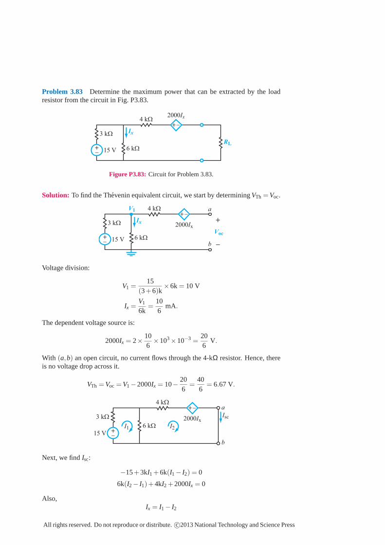
Problem 3.83 Determine the maximum power that can be extracted by the loadresistor from the circuit in Fig. P3.83.
2000Ix
6 kΩ
3 kΩ
4 kΩ
RL
Ix
15 V
+_
+_
Figure P3.83: Circuit for Problem 3.83.
Solution: To find the Thevenin equivalent circuit, we start by determiningVTh = Voc.
2000Ix
6 kΩ
3 kΩ
4 kΩ
Ix
15 V
+_
+_
Voc
a
b
V1
+
_
Voltage division:
V1 =15
(3+6)k×6k = 10 V
Ix =V1
6k=
106
mA.
The dependent voltage source is:
2000Ix = 2×106×103×10−3
=206
V.
With (a,b) an open circuit, no current flows through the 4-kΩ resistor. Hence, thereis no voltage drop across it.
VTh = Voc = V1−2000Ix = 10−206
=406
= 6.67 V.
2000Ix
6 kΩ
3 kΩ
4 kΩ
15 V
+_
+_
Isc
a
b
I1 I2
Next, we findIsc:
−15+3kI1 +6k(I1− I2) = 0
6k(I2− I1)+4kI2 +2000Ix = 0
Also,Ix = I1− I2
All rights reserved. Do not reproduce or distribute.c©2013 National Technology and Science Press

Solution yields:
I1 = 2.5 mA, I2 = 1.25 mA.
Isc = I2 = 1.25 mA.
RTh =Voc
Isc=
6.671.25×10−3 = 5.33 kΩ.
Hence,RL = 5.33 kΩ extracts maximum power.
RL
RTh = 5.33 kΩ
6.67 V
I
+_ 5.33 kΩ
I =6.67
2×5.33= 0.625 mA
Pmax = I2RL = (0.625×10⁻³)2×5.33×103
= 2.09 (mW).
All rights reserved. Do not reproduce or distribute.c©2013 National Technology and Science Press
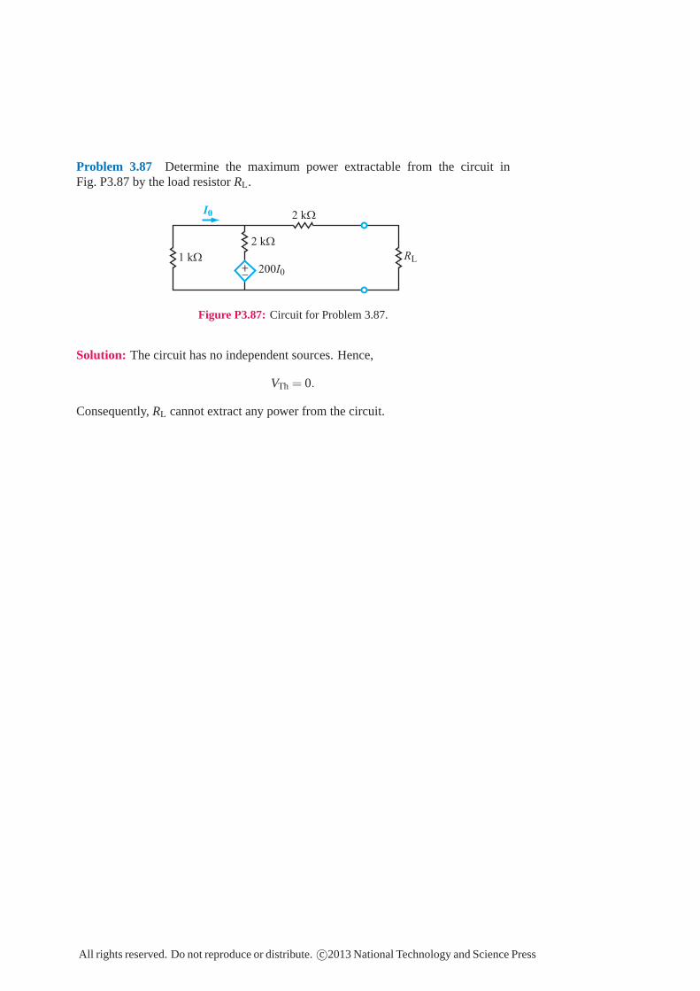
Problem 3.87 Determine the maximum power extractable from the circuit inFig. P3.87 by the load resistor RL.
200I0
1 kΩ
2 kΩ
2 kΩ
I0
RL
+_
Figure P3.87: Circuit for Problem 3.87.
Solution: The circuit has no independent sources. Hence,
VTh = 0.
Consequently, RL cannot extract any power from the circuit.
All rights reserved. Do not reproduce or distribute. c©2013 National Technology and Science Press
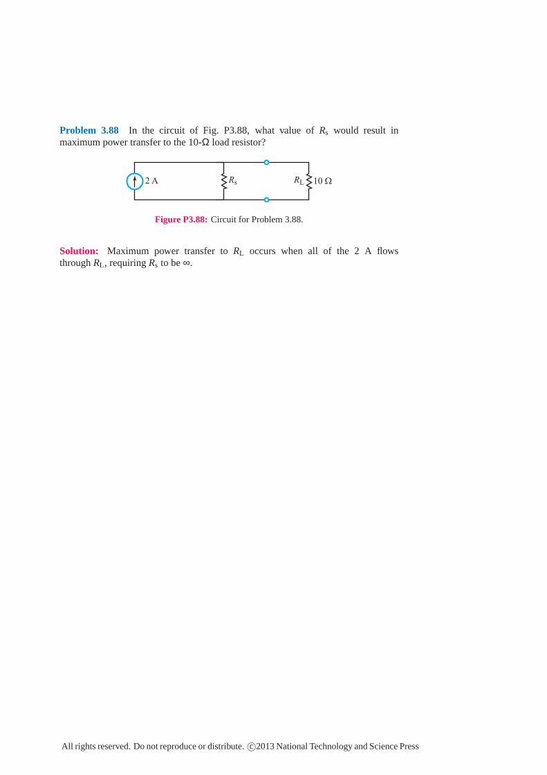
Problem 3.88 In the circuit of Fig. P3.88, what value ofRs would result inmaximum power transfer to the 10-Ω load resistor?
2 A RLRs 10 Ω
Figure P3.88: Circuit for Problem 3.88.
Solution: Maximum power transfer toRL occurs when all of the 2 A flowsthroughRL , requiringRs to be∞.
All rights reserved. Do not reproduce or distribute.c©2013 National Technology and Science Press


![FAN7711 Ballast Control Integrated Circuit - Digi-Key Sheets/Fairchild PDFs/FAN7711.pdf · FAN7711 Ballast Control Integrated Circuit) 1 3 0 circuit [.] ...](https://static.fdocument.org/doc/165x107/5acfdb947f8b9a1d328d8e40/fan7711-ballast-control-integrated-circuit-digi-key-sheetsfairchild-pdfsfan7711pdffan7711.jpg)