Experiment 17: Kirchhoff’s Laws for Circuits · In performing the experiment, measured values...
5
Experiment 17: Kirchhoff’s Laws for Circuits Figure 17.1: Kirchhoff’s Law Circuit Board Figure 17.2: Schematic for Kirchhoff’s Circuit EQUIPMENT (1) Universal Circuit Board (2) D-Cell Batteries (1.5 V) (2) Battery Holders (4) Alligator Clips (1) DMM (5) Resistors: R 1 = 10 Ω Resistor R 2 = 12 Ω Resistor R 3 = 15 Ω Resistor R 4 = 18 Ω Resistor R 5 = 22 Ω Resistor 89
Transcript of Experiment 17: Kirchhoff’s Laws for Circuits · In performing the experiment, measured values...
Experiment 17: Kirchhoff’s Laws for
Circuits
Figure 17.1: Kirchhoff’s Law Circuit Board
Figure 17.2: Schematic for Kirchhoff’s Circuit
EQUIPMENT
(1) Universal Circuit Board(2) D-Cell Batteries (1.5 V)(2) Battery Holders(4) Alligator Clips(1) DMM
(5) Resistors:R1 = 10 Ω ResistorR2 = 12 Ω ResistorR3 = 15 Ω ResistorR4 = 18 Ω ResistorR5 = 22 Ω Resistor
89
90 Experiment 17: Kirchhoff’s Laws for Circuits
Advance Reading
Text: Kirchhoff’s Voltage Law, Kirchhoff’s CurrentLaw
Lab Manual: Appendix A: Math Review (solving 3equations with 3 unknowns)
Objective
The objective of this experiment is to apply Kirchhoff’srules for circuits to a two-loop circuit to determine thethree currents in the circuit and the electric potentialdifferences around each loop.
Theory
The two basic laws of electricity that are most usefulin analyzing circuits are Kirchhoff’s laws for currentand voltage.
Kirchhoff’s Current Law (The Junction Rule) statesthat at any junction (node) of a circuit, the algebraicsum of all the currents is zero (sum of the currentsentering the junction equals the sum of the currentsleaving the junction). In other words, electric chargeis conserved.
ΣIin = ΣIout (17.1)
Kirchhoff’s Voltage Law (The Loop Rule) states thataround any closed loop or path in a circuit, the alge-braic sum of all electric potential differences is equalto zero.
ΣVi = 0 (17.2)
To calculate magnitudes of current and voltage in acircuit like Fig. 17.2, you will need to write three equa-tions, making use of both the loop and junction rules.This results in three equations with three unknowns.For this experiment, you will measure εi and Ri, thensolve for the three currents, Ii.
One might be able to guess the direction of currentflow in a circuit, given a circuit such as the one in thisexperiment. However, as long as the current directionchosen at the beginning is used consistently through-out the calculation, the calculation will be correct. Forthe purposes of this experiment, all currents will be as-sumed to be in the direction shown in Fig 17.2. If any
current is measured or calculated to be negative, thatcurrent actually flows in the opposite direction of whatis indicated in Fig 17.2.
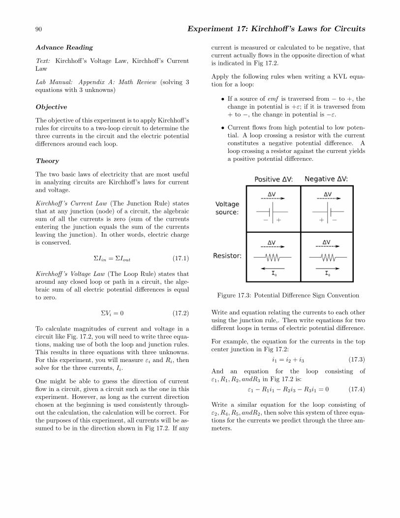
Apply the following rules when writing a KVL equa-tion for a loop:
• If a source of emf is traversed from − to +, thechange in potential is +ε; if it is traversed from+ to −, the change in potential is −ε.
• Current flows from high potential to low poten-tial. A loop crossing a resistor with the currentconstitutes a negative potential difference. Aloop crossing a resistor against the current yieldsa positive potential difference.
Figure 17.3: Potential Difference Sign Convention
Write and equation relating the currents to each otherusing the junction rule,. Then write equations for twodifferent loops in terms of electric potential difference.
For example, the equation for the currents in the topcenter junction in Fig 17.2:
i1 = i2 + i3 (17.3)
And an equation for the loop consisting ofε1, R1, R2, andR3 in Fig 17.2 is:
ε1 −R1i1 −R2i3 −R3i1 = 0 (17.4)
Write a similar equation for the loop consisting ofε2, R4, R5, andR2, then solve this system of three equa-tions for the currents we predict through the three am-meters.
Prelab 17: Kirchhoff’s Laws for Circuits 91
Name:
1. Write the equation, then briefly explain: (20 pts ea.)
(a) Kirchhoff’s Voltage Law (KVL)
(b) Kirchhoff’s Current Law (KCL)
2. Consider the circuit shown in Fig. 17.2 and the Equipment list on Page 89. Use Kirchhoff’s Current Law andVoltage Law to solve for the theoretical currents, i1, i2, andi3.
In performing the experiment, measured values will be used for the emfs and resistances. For the pre-lab, use thenominal values as stated in the Equipment list.
(a) Write the system of three equations. (30 pts)
(b) Solve for I1, I2, andI3 using substitution. (30 pts)
92 Experiment 17: Kirchhoff’s Laws for Circuits
PROCEDURE
PART 1: Loop Method - Calculations
1. Determine the nominal resistance and tolerance ofeach resistor by reading its color code (Table 15.1,Page 78). They should have the following approxi-mate resistances:
R1 = 10 ΩR2 = 12 ΩR3 = 15 ΩR4 = 18 ΩR5 = 22 Ω
2. Measure the resistance of each resistor using anohmmeter.
3. Construct the circuit shown in Fig. 17.2. Do notconnect the ammeter.
4. Measure ε of the two batteries using a voltmeter.They should each be at least 1.1 V. Turn off theDMM and disconnect the batteries so they do notdrain.
5. Using your knowledge of the loop and junction rules,write three equations relating].
6. Solve these equations by substitution to find thetheoretical currents. A negative value simply indi-cates the current flows in the other direction.
PART 2: Current & Voltage Laws Applied
7. Connect the batteries to the circuit.
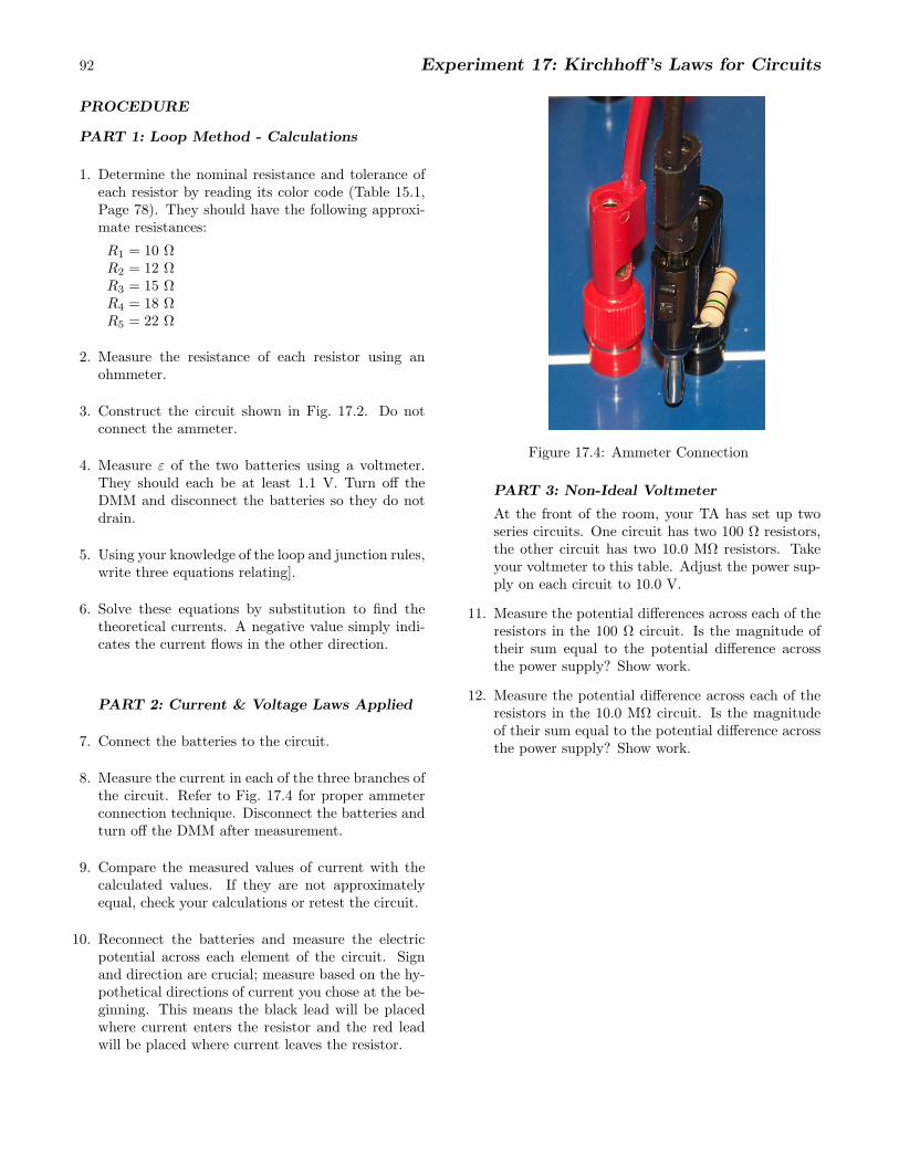
8. Measure the current in each of the three branches ofthe circuit. Refer to Fig. 17.4 for proper ammeterconnection technique. Disconnect the batteries andturn off the DMM after measurement.
9. Compare the measured values of current with thecalculated values. If they are not approximatelyequal, check your calculations or retest the circuit.
10. Reconnect the batteries and measure the electricpotential across each element of the circuit. Signand direction are crucial; measure based on the hy-pothetical directions of current you chose at the be-ginning. This means the black lead will be placedwhere current enters the resistor and the red leadwill be placed where current leaves the resistor.
Figure 17.4: Ammeter Connection
PART 3: Non-Ideal Voltmeter
At the front of the room, your TA has set up twoseries circuits. One circuit has two 100 Ω resistors,the other circuit has two 10.0 MΩ resistors. Takeyour voltmeter to this table. Adjust the power sup-ply on each circuit to 10.0 V.
11. Measure the potential differences across each of theresistors in the 100 Ω circuit. Is the magnitude oftheir sum equal to the potential difference acrossthe power supply? Show work.
12. Measure the potential difference across each of theresistors in the 10.0 MΩ circuit. Is the magnitudeof their sum equal to the potential difference acrossthe power supply? Show work.
Experiment 17: Kirchhoff’s Laws for Circuits 93
QUESTIONS
1. Explain what effect the DMM will have on the cir-cuit when inserted to measure current.
2. Do the values from Part 2 verify Kirchhoff’s Cur-rent Law?
3. Do the values from Part 2 verify Kirchhoff’s VoltageLaw?
4. Would disconnecting the emf source on the left loopof the circuit, ε1, affect the current I2? Calculatewhat I2 is for this case. What about I3.
5. A voltmeter is connected in parallel to a resistorwhen measuring Vi. Remember that the internalresistance of the DMM, when used as a voltmeter,is approximately 10 MΩ. Calculate Reqof the volt-meter connected to a resistor in each circuit ofPart 3.
6. Use the above information to discuss why the volt-age measured across the 10 MΩ resistors did notequal the voltage measured across the power sup-ply.