EuroBeam from Greentram Software - Eurocode EC2, EC3 · PDF fileCalculate Buckling Resistance...
2
EuroBeam from Greentram Software Typical calculations produced by the pre-release version Printed 15 Apr 2010 15:29 EuroBeam 1.00x 0 SCIExamples.eub Column calculation to EN1993-1-1 using S275 steel Location: SCI Worked Examples 13: Column with reactions Length: 5.0 m. Pos Dur Load kN Factored load Offset Moment y-y Moment z-z 6.10a 6.10b 6.10a 6.10b 6.10a 6.10b +1 +2 3+ +4 A G Load from above 377/1.35 = 279.3 377.0 348.7 1 G React 147/1.35 = 108.9 147.0 136.0 100 29.64 27.41 3 G React 37/1.35 = 27.4 37.0 34.2 100 3.83 3.55 4 G React 28/1.35 = 20.7 28.0 25.9 100 -2.90 -2.68 Total load 436.3 589.0 544.8 29.64 27.41 0.93 0.86 Load offsets are measured in mm. from faces of member; moments in kNm Use: 203 x 203 x 46 UKC Section properties: Gross area, A g = 58.7cm 2 T = 11.0mm r y = 5.13 cm D = 203.2 mm t = 7.20 mm W pl,y = 497 cm 3 Z y = 152 cm 3 Design strength, p y = 275 N/mm 2 ε = 0.924 Classification: Flange: c/t = 88.0/11.0 = 8.00 <= 9 ε (8.32): Class 1, plastic Major axis: L Ex = 1.0L = 5.00 m. Slenderness, λ y = 5.00 x 100/8.82 = 56.7 Minor axis: L Ey = 0.5L = 2.50 m. Slenderness, λ z = 2.50 x 100/5.13 = 48.7 Compression: Design axial load, N Ed = 589.0 kN Design compression resistance, N c,Rd = Af y / γ M0 = 58.7 x 100 x 275/(1.0 x 1000) = 1,614 kN Calculate flexural buckling resistances, N c,Rd Buckling about major axis λ y = λ y /93.9 ε = 56.7/(93.9 x 0.924) = 0.653 Use curve b: α = 0.340 φ = 0.5(1 + α ( λ -0.2) λ 2 ) = 0.790 χ = 1/( φ + ( φ 2 - λ 2 )) = 0.810 Design buckling resistance, N c,Rd = χ A fy / γ M1 = 0.810 x 58.7 x 1000 x 275/(1.0 x 1000) = 1,307 kN OK Buckling about minor axis λ z = λ z /93.9 ε = 48.7/ (93.9 x 0.924) = 0.561 Use curve c: α = 0.490 φ = 0.5(1 + α ( λ -0.2) λ 2 ) = 0.746 χ = 1/( φ + ( φ 2 - λ 2 )) = 0.808 Design buckling resistance, N c,Rd = χ A fy / γ M1 = 0.808 x 58.7 x 1000 x 275/(1.0 x 1000) = 1,304 kN OK Ben ding about y-y (major) axis: Design moment, M y,Ed : 29.6 kNm Classification: Flange: c/t = 88.0/11.0 = 8.00 <= 9 ε (8.32): Class 1, plastic Table 5.2 Web: c/t = 160.8/7.2 = 22.3 <= 72 ε (66.6): Class 1, plastic Moment capacity, M c,y,Rd = p y .W pl,y = 275 x 497/1000 = 136.7 kNm OK Calculate Buckling Resistance Moment Design buckling resistance moment, M b,Rd = χ LT,mod .M c,Rd M cr = C 1 ( π 2 EI z /L eff 2 )[ (I w /I z + L eff 2 GI t /( π 2 EI z )] = 579.6 NCCI SN003 2(1) λ LT = (M c,y,Rd /M cr ) = 0.486 λ LT,0 = 0.4 Β = 0.75 [EC3 UK NA 2.17] Use buckling curve b: α = 0.340 [EC3 Tables 6.3/6.4 NA2.17] φ LT = 0.5[1 + α LT ( λ LT - λ LT,0 ) + Β λ LT 2 ] = 0.603 χ LT = 1/[ φ LT + ( φ LT 2 - Β λ LT 2 )] = 0.966 [EC3 (6.56)] M b,y,Rd = φ LT .M c,y,Rd / γ M = 0.603 x 136.7/1.0 = 132.0 kNm Ben ding about z-z (minor) axis: Design moment, M z,Ed : 0.932 kNm Moment capacity, M z,Rd = f y .W pl,y = 275 x 231.0/1000 = 63.53 kNm
Transcript of EuroBeam from Greentram Software - Eurocode EC2, EC3 · PDF fileCalculate Buckling Resistance...
EuroBeam from Greentram SoftwareTypical calculations produced by the pre-release version
Printed 15 Apr 2010 15:29
EuroBeam 1.00x 0 SCIExamples.eub
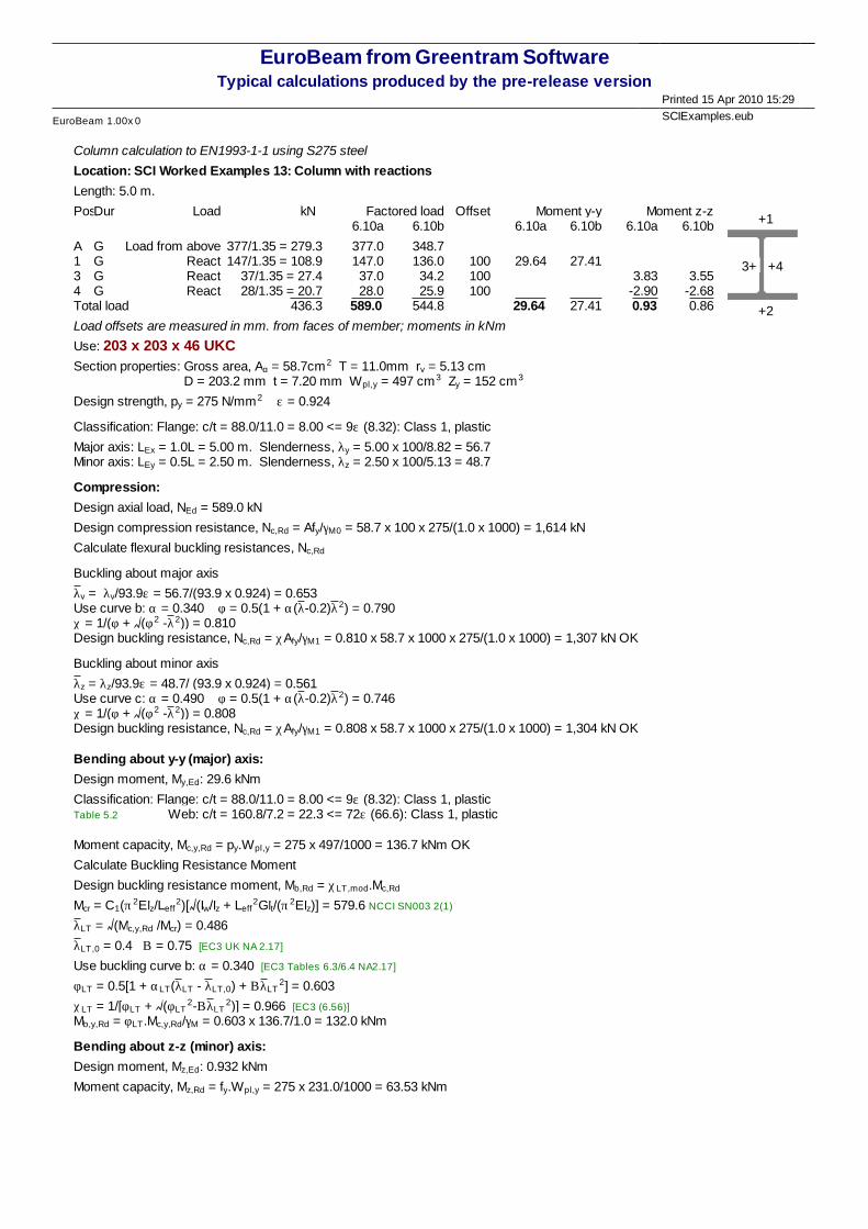
Column calculation to EN1993-1-1 using S275 steel
Location: SCI Worked Examples 13: Column with reactions
Length: 5.0 m.
PosDur Load kN Factored load Offset Moment y-y Moment z-z 6.10a 6.10b 6.10a 6.10b 6.10a 6.10b +1
+2
3+ +4
A G Load from above 377/1.35 = 279.3 377.0 348.71 G React 147/1.35 = 108.9 147.0 136.0 100 29.64 27.413 G React 37/1.35 = 27.4 37.0 34.2 100 3.83 3.554 G React 28/1.35 = 20.7 28.0 25.9 100 -2.90 -2.68Total load 436.3 589.0 544.8 29.64 27.41 0.93 0.86
Load offsets are measured in mm. from faces of member; moments in kNm
Use: 203 x 203 x 46 UKCSection properties: Gross area, Ag = 58.7cm2 T = 11.0mm ry = 5.13 cm
D = 203.2 mm t = 7.20 mm Wpl,y = 497 cm3 Zy = 152 cm3
Design strength, py = 275 N/mm2 e = 0.924
Classification: Flange: c/t = 88.0/11.0 = 8.00 <= 9e (8.32): Class 1, plastic
Major axis: LEx = 1.0L = 5.00 m. Slenderness, ly = 5.00 x 100/8.82 = 56.7Minor axis: LEy = 0.5L = 2.50 m. Slenderness, lz = 2.50 x 100/5.13 = 48.7
Compression:
Design axial load, NEd = 589.0 kN
Design compression resistance, Nc,Rd = Afy/gM0 = 58.7 x 100 x 275/(1.0 x 1000) = 1,614 kN
Calculate flexural buckling resistances, Nc,Rd
Buckling about major axis
ly = ly/93.9e = 56.7/(93.9 x 0.924) = 0.653Use curve b: a = 0.340 f = 0.5(1 + a(l-0.2)l2) = 0.790c = 1/(f + (f2 -l2)) = 0.810Design buckling resistance, Nc,Rd = cAfy/gM1 = 0.810 x 58.7 x 1000 x 275/(1.0 x 1000) = 1,307 kN OK
Buckling about minor axis
lz = lz/93.9e = 48.7/ (93.9 x 0.924) = 0.561Use curve c: a = 0.490 f = 0.5(1 + a(l-0.2)l2) = 0.746c = 1/(f + (f2 -l2)) = 0.808Design buckling resistance, Nc,Rd = cAfy/gM1 = 0.808 x 58.7 x 1000 x 275/(1.0 x 1000) = 1,304 kN OK
Bending about y-y (major) axis:
Design moment, My,Ed: 29.6 kNm
Classification: Flange: c/t = 88.0/11.0 = 8.00 <= 9e (8.32): Class 1, plasticTable 5.2 Web: c/t = 160.8/7.2 = 22.3 <= 72e (66.6): Class 1, plastic
Moment capacity, Mc,y,Rd = py.Wpl,y = 275 x 497/1000 = 136.7 kNm OK
Calculate Buckling Resistance Moment
Design buckling resistance moment, Mb,Rd = cLT,mod.Mc,Rd
Mcr = C1(p2EIz/Leff2)[ (Iw/Iz + Leff
2GIt/(p2EIz)] = 579.6 NCCI SN003 2(1)
lLT = (Mc,y,Rd /Mcr) = 0.486
lLT,0 = 0.4 B = 0.75 [EC3 UK NA 2.17]
Use buckling curve b: a = 0.340 [EC3 Tables 6.3/6.4 NA2.17]
fLT = 0.5[1 + aLT(lLT - lLT,0) + BlLT2] = 0.603
cLT = 1/[fLT + (fLT2-BlLT
2)] = 0.966 [EC3 (6.56)]
Mb,y,Rd = fLT.Mc,y,Rd/gM = 0.603 x 136.7/1.0 = 132.0 kNm
Bending about z-z (minor) axis:
Design moment, Mz,Ed: 0.932 kNm
Moment capacity, Mz,Rd = fy.Wpl,y = 275 x 231.0/1000 = 63.53 kNm
EuroBeam from Greentram SoftwareTypical calculations produced by the pre-release version
Printed 15 Apr 2010 15:29
EuroBeam 1.00x 0 SCIExamples.eub
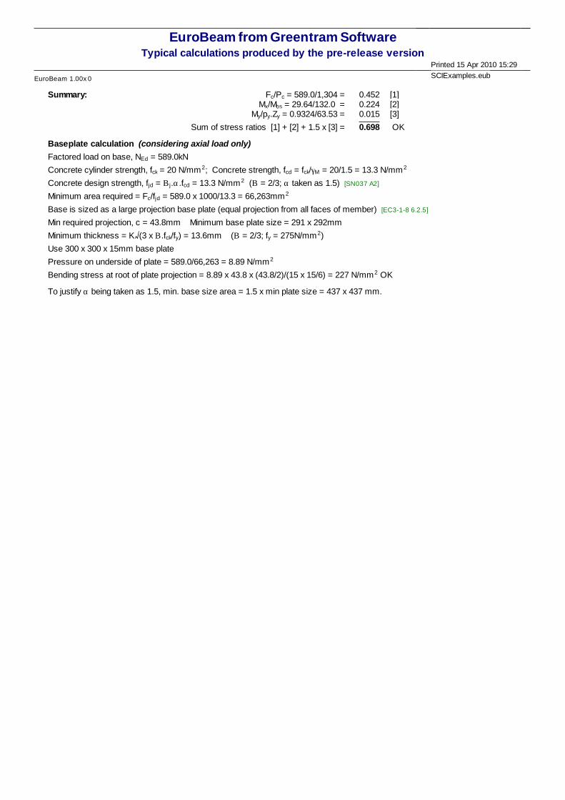
Summary: = 589.0/1,304 =c/PcF 0.452 [1] = 29.64/132.0 =bs/MxM 0.224 [2] = 0.9324/63.53 =y.Zy/pyM 0.015 [3]
Sum of stress ratios [1] + [2] + 1.5 x [3] = 0.698 OK
Baseplate calculation (considering axial load only)
Factored load on base, NEd = 589.0kN
Concrete cylinder strength, fck = 20 N/mm2; Concrete strength, fcd = fck/gM = 20/1.5 = 13.3 N/mm2
Concrete design strength, fjd = Bj.a.fcd = 13.3 N/mm2 (B = 2/3; a taken as 1.5) [SN037 A2]
Minimum area required = Fc/fjd = 589.0 x 1000/13.3 = 66,263mm2
Base is sized as a large projection base plate (equal projection from all faces of member) [EC3-1-8 6.2.5]
Min required projection, c = 43.8mm Minimum base plate size = 291 x 292mm
Minimum thickness = K (3 x B.fck/fy) = 13.6mm (B = 2/3; fy = 275N/mm2)
Use 300 x 300 x 15mm base plate
Pressure on underside of plate = 589.0/66,263 = 8.89 N/mm2
Bending stress at root of plate projection = 8.89 x 43.8 x (43.8/2)/(15 x 15/6) = 227 N/mm2 OK
To justify a being taken as 1.5, min. base size area = 1.5 x min plate size = 437 x 437 mm.