Concrete stress blocks of MC 90 and EC2. How safe are … axial load-bending moment interaction...
6
Tailor Made Concrete Structures – Walraven & Stoelhorst (eds) © 2008Taylor & Francis Group, London, ISBN 978-0-415-47535-8 Concrete stress blocks of MC 90 and EC2. How safe are they? L.C.D. Shehata Universidade Federal Fluminense, Niterói, Brasil A.L. Paula Engevix, Rio de Janeiro, Brasil I.A.E.M. Shehata COPPE- Universidade Federal do Rio de Janeiro, Rio de Janeiro, Brasil ABSTRACT: The utilization of High Strength Concrete (HSC) is more advantageous in structural elements under compression and the compressive stress-strain relationship is a relevant characteristic of the concrete needed for the design of those elements. For cross-sections design, the CEB-FIP MC 90 (1993) and the EN1992- 1-1 (2004) permit curved-rectangular idealized concrete stress blocks and simplified rectangular ones. If the level of the axial load is relatively high, those stress blocks can lead to quite different strength capacity of HSC cross-sections. The experimental strengths of 403 elements subjected to pure axial load or to combined axial load and bending moment found in the literature are compared to the theoretical ones obtained considering those compressive stress diagrams for the concrete. The analysis of that comparison gives an idea about the level of safety related to the different design procedures, relevant information for codes writers and those who want to design HSC structures. 1 INTRODUCTION The use of HSC has gradually increased during the last decades and nowadays most of national and interna- tional codes do consider concretes with f ck > 50 MPa. These codes specify a maximum value for f ck around 80 MPa to 95 MPa, but this limit will probably increase in the future. Various concrete stress blocks have been proposed in the literature for designing cross-sections of HSC elements under compression and the adoption of dif- ferent stress blocks can lead to quite different theoret- ical axial load-bending moment interaction diagrams. The differences between the interaction diagrams are greater for cross-sections subjected predominantly to axial load and greater values of f ck . The CEB-FIP MC 90 (1993) and the EN1992-1-1 (2004) permit curved-rectangular idealized concrete stress blocks and simplified rectangular ones, while the EN1992-1-1 gives also the possibility of using a bi-linear stress block. In this work, the comparisons between experimen- tal and calculated strengths of tested columns give an idea of the level of safety related to the use of the curved-rectangular and rectangular concrete stress blocks of CEB-FIP MC 90 (1993) and EN1992-1-1 (2004). In general, particularly for greater values of f ck , the theoretical strengths given by the rectangu- lar stress block are smaller than the ones obtained using the curved-rectangular concrete diagram of the same code. 2 COMPARISONS BETWEEN EXPERIMENTAL AND THEORETICAL STRENGTHS Experimental strengths were taken from 403 tests available in the literature and presented in 25 differ- ent reports (see references). The tested specimens had square (269) or rectangular cross-sections (134), were made of normal weight concrete and subjected to pure axial load (123) or to combined axial load and bending moment (280). For the sake of comparison, 88 spec- imens made of concrete with f c ≤ 50 MPa, tested by the same researchers that tested the ones of HSC, were considered. The selected specimens had length/smaller cross- section dimension ratio (L/h) greater than or equal to 3 and, with the exception of 28 reported by Chuang & Kong 1997, Claeson et al. 1996, Chuang et al. 2000) stirrups spacing less than the smaller cross- section dimension. These 28 columns were considered 599
Transcript of Concrete stress blocks of MC 90 and EC2. How safe are … axial load-bending moment interaction...
Tailor Made Concrete Structures – Walraven & Stoelhorst (eds)© 2008 Taylor & Francis Group, London, ISBN 978-0-415-47535-8
Concrete stress blocks of MC 90 and EC2. How safe are they?
L.C.D. ShehataUniversidade Federal Fluminense, Niterói, Brasil
A.L. PaulaEngevix, Rio de Janeiro, Brasil
I.A.E.M. ShehataCOPPE- Universidade Federal do Rio de Janeiro, Rio de Janeiro, Brasil
ABSTRACT: The utilization of High Strength Concrete (HSC) is more advantageous in structural elementsunder compression and the compressive stress-strain relationship is a relevant characteristic of the concreteneeded for the design of those elements. For cross-sections design, the CEB-FIP MC 90 (1993) and the EN1992-1-1 (2004) permit curved-rectangular idealized concrete stress blocks and simplified rectangular ones. If thelevel of the axial load is relatively high, those stress blocks can lead to quite different strength capacity of HSCcross-sections. The experimental strengths of 403 elements subjected to pure axial load or to combined axialload and bending moment found in the literature are compared to the theoretical ones obtained considering thosecompressive stress diagrams for the concrete. The analysis of that comparison gives an idea about the level ofsafety related to the different design procedures, relevant information for codes writers and those who want todesign HSC structures.
1 INTRODUCTION
The use of HSC has gradually increased during the lastdecades and nowadays most of national and interna-tional codes do consider concretes with fck > 50 MPa.These codes specify a maximum value for fck around80 MPa to 95 MPa, but this limit will probably increasein the future.
Various concrete stress blocks have been proposedin the literature for designing cross-sections of HSCelements under compression and the adoption of dif-ferent stress blocks can lead to quite different theoret-ical axial load-bending moment interaction diagrams.The differences between the interaction diagrams aregreater for cross-sections subjected predominantly toaxial load and greater values of fck.
The CEB-FIP MC 90 (1993) and the EN1992-1-1(2004) permit curved-rectangular idealized concretestress blocks and simplified rectangular ones, whilethe EN1992-1-1 gives also the possibility of using abi-linear stress block.
In this work, the comparisons between experimen-tal and calculated strengths of tested columns givean idea of the level of safety related to the use ofthe curved-rectangular and rectangular concrete stressblocks of CEB-FIP MC 90 (1993) and EN1992-1-1
(2004). In general, particularly for greater values offck, the theoretical strengths given by the rectangu-lar stress block are smaller than the ones obtainedusing the curved-rectangular concrete diagram of thesame code.
2 COMPARISONS BETWEEN EXPERIMENTALAND THEORETICAL STRENGTHS
Experimental strengths were taken from 403 testsavailable in the literature and presented in 25 differ-ent reports (see references). The tested specimens hadsquare (269) or rectangular cross-sections (134), weremade of normal weight concrete and subjected to pureaxial load (123) or to combined axial load and bendingmoment (280). For the sake of comparison, 88 spec-imens made of concrete with fc ≤ 50 MPa, tested bythe same researchers that tested the ones of HSC, wereconsidered.
The selected specimens had length/smaller cross-section dimension ratio (L/h) greater than or equal to 3and, with the exception of 28 reported by Chuang &Kong 1997, Claeson et al. 1996, Chuang et al.2000) stirrups spacing less than the smaller cross-section dimension. These 28 columns were considered
599
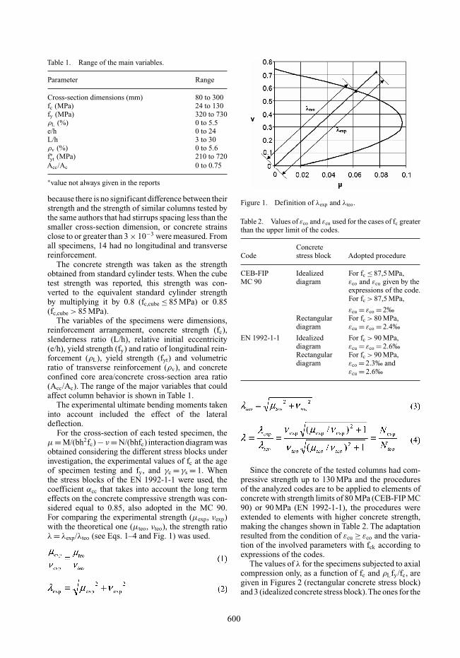
Table 1. Range of the main variables.
Parameter Range
Cross-section dimensions (mm) 80 to 300fc (MPa) 24 to 130fy (MPa) 320 to 730ρL (%) 0 to 5.5e/h 0 to 24L/h 3 to 30ρv (%) 0 to 5.6f∗yt (MPa) 210 to 720Acc/Ac 0 to 0.75
∗value not always given in the reports
because there is no significant difference between theirstrength and the strength of similar columns tested bythe same authors that had stirrups spacing less than thesmaller cross-section dimension, or concrete strainsclose to or greater than 3 × 10⁻³ were measured. Fromall specimens, 14 had no longitudinal and transversereinforcement.
The concrete strength was taken as the strengthobtained from standard cylinder tests. When the cubetest strength was reported, this strength was con-verted to the equivalent standard cylinder strengthby multiplying it by 0.8 (fc,cube ≤ 85 MPa) or 0.85(fc,cube > 85 MPa).
The variables of the specimens were dimensions,reinforcement arrangement, concrete strength (fc),slenderness ratio (L/h), relative initial eccentricity(e/h), yield strength (fy) and ratio of longitudinal rein-forcement (ρL), yield strength (fyt) and volumetricratio of transverse reinforcement (ρv), and concreteconfined core area/concrete cross-section area ratio(Acc/Ac). The range of the major variables that couldaffect column behavior is shown in Table 1.
The experimental ultimate bending moments takeninto account included the effect of the lateraldeflection.
For the cross-section of each tested specimen, theµ = M/(bh2fc) − ν = N/(bhfc) interaction diagram wasobtained considering the different stress blocks underinvestigation, the experimental values of fc at the ageof specimen testing and fy, and γc = γs = 1. Whenthe stress blocks of the EN 1992-1-1 were used, thecoefficient αcc that takes into account the long termeffects on the concrete compressive strength was con-sidered equal to 0.85, also adopted in the MC 90.For comparing the experimental strength (µexp, νexp)with the theoretical one (µteo, νteo), the strength ratioλ = λexp/λteo (see Eqs. 1–4 and Fig. 1) was used.
Figure 1. Definition of λexp and λteo.
Table 2. Values of εco and εcu used for the cases of fc greaterthan the upper limit of the codes.
ConcreteCode stress block Adopted procedure
CEB-FIP Idealized For fc ≤ 87,5 MPa,MC 90 diagram εco and εcu given by the
expressions of the code.For fc > 87,5 MPa,
εcu = εco = 2‰Rectangular For fc > 80 MPa,diagram εcu = εco = 2.4‰
EN 1992-1-1 Idealized For fc > 90 MPa,diagram εcu = εco = 2.6‰Rectangular For fc > 90 MPa,diagram εco = 2.3‰ and
εcu = 2.6‰
Since the concrete of the tested columns had com-pressive strength up to 130 MPa and the proceduresof the analyzed codes are to be applied to elements ofconcrete with strength limits of 80 MPa (CEB-FIP MC90) or 90 MPa (EN 1992-1-1), the procedures wereextended to elements with higher concrete strength,making the changes shown in Table 2. The adaptationresulted from the condition of εcu ≥ εco and the varia-tion of the involved parameters with fck according toexpressions of the codes.
The values of λ for the specimens subjected to axialcompression only, as a function of fc and ρLfy/fc, aregiven in Figures 2 (rectangular concrete stress block)and 3 (idealized concrete stress block).The ones for the
600
Figure 2. Values of λ for the specimens under pure axialload related to the rectangular concrete stress block.
Figure 3. Values of λ for the specimens under pure axialload related to the idealized concrete stress block.
601
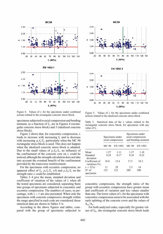
Figure 4. Values of λ for the specimens under combinedactions related to the rectangular concrete stress block.
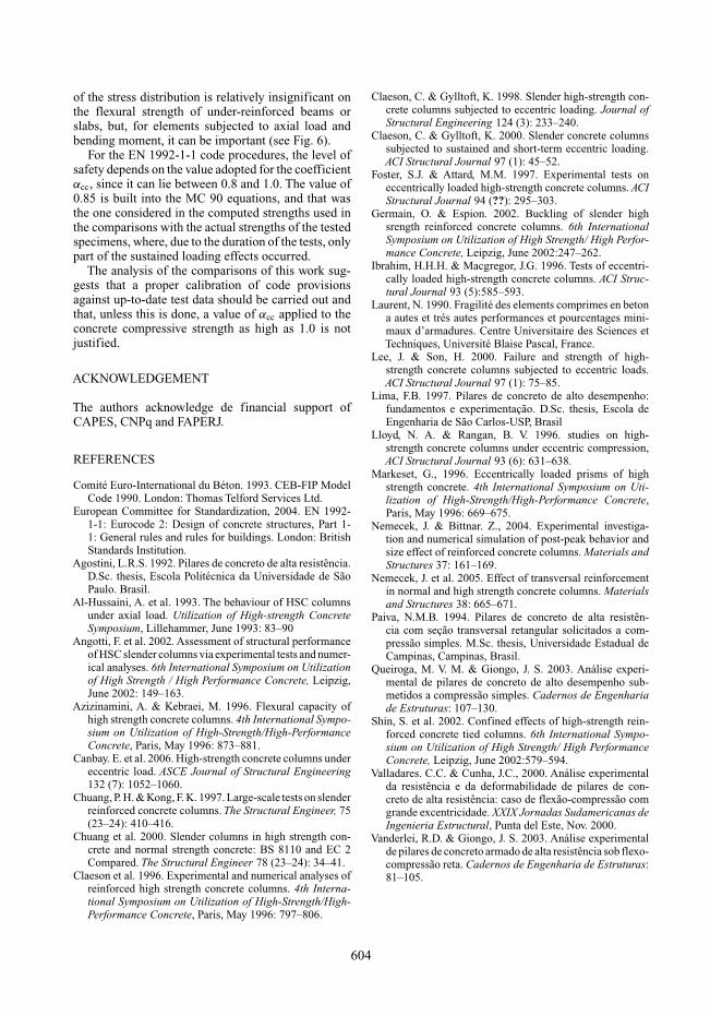
specimens subjected to axial compression and bendingmoment, as a function of fc, are in Figures 4 (rectan-gular concrete stress block) and 5 (idealized concretestress block).
Figure 2 shows that, for concentric compression, λtends to increase with increasing fc and to decreasewith increasing ρLfy/fc, particularly when the MC 90rectangular stress block is used. This does not happenwhen the idealized concrete stress block is adopted.Due to the small values of ρvfyt/fc, no influence ofthe confinement of the concrete core on λ could benoticed, although the strength calculation does not takeinto account the eventual benefit of the confinementprovided by the transverse reinforcement.
For the specimens with eccentric compression, noapparent effect of fc, ρLfy/fc, e/h and ρvfyt/fc on thestrength ratio λ could be established.
Tables 3–4 give the mean, standard deviation andcoefficient of variation of the values of λ when allthe tested specimens are considered, separating theminto groups of specimens subjected to concentric andeccentric compression. The numbers of cases, in per-centage, with λ < 1 are also presented. When only thespecimens with concrete compressive strength withinthe range specified in each code are considered, thosestatistical data are shown in Tables 5–6.
According to the above figures and tables, com-pared with the group of specimens subjected to
Figure 5. Values of λ for the specimens under combinedactions related to the idealized concrete stress block.
Table 3. Statistical data of the λ values related to therectangular concrete stress block, for specimens with anyvalue of fc.
Specimens underSpecimens under axial compressionaxial compression and bending moment
MC 90 EN 1992 MC 90 EN 1992
Mean 1.27 1.11 1.37 1.18Standard 0.24 0.17 0.24 0.22
deviationCoefficient of 18.8 15.6 17.5 18.3
variation (%)λ < 1(%) 11 29 2.5 14No of 123 123 280 280specimens
concentric compression, the strength ratios of thegroup with eccentric compression have greater meanand coefficient of variation and less values smallerthan one. The lower values of λ for the specimens withconcentric compression seem to be associated with theearly splitting of the concrete cover and the values ofAcc/Ac.
For both analyzed codes, especially for greater val-ues of fck, the rectangular concrete stress block leads
602

Table 4. Statistical data of the λ values related to theidealized concrete stress block, for specimens with anyvalue of fc.
Specimens underSpecimens under axial compressionaxial compression and bending moment
MC 90 EN 1992 MC 90 EN 1992
Mean 1.00 0.98 1.14 1.13Standard 0.14 0.15 0.19 0.19
deviationCoefficient of 14.5 15.0 16.9 17.2
variation (%)λ < 1(%) 57 60 18 20No of 123 123 280 280specimens
Table 5. Statistical data of the λ values related to the rect-angular concrete stress block, for specimens with fc valuewithin the range specified in the code.
Specimens underSpecimens under axial compressionaxial compression and bending moment
MC 90 EN 1992 MC 90 EN 1992
Mean 1.16 1.08 1.30 1.17Standard 0.19 0.16 0.21 0.21
deviationCoefficient of 16.0 15.0 16.6 18.3
variation (%)λ < 1(%) 15 34 2.5 15No of 80 106 158 200specimens
Table 6. Statistical data of the λ values related to the ideal-ized concrete stress block, for specimens with fc value withinthe range specified in the code.
Specimens underSpecimens under axial compressionaxial compression and bending moment
MC 90 EN 1992 MC 90 EN 1992
Mean 1.10 0.97 1.15 1.13Standard 0.15 0.15 0.21 0.21
deviationCoefficient of 15.0 15.2 18.6 18.3
variation (%)λ < 1(%) 54 61 17 22No of 80 106 158 200specimens
Figure 6. Interaction diagrams for a square cross-section(b = h = 200 mm, fy = 500 MPa, ρL = 1.25%:4 longitudinalbars), γc = γs = 1, αcc = 0.85.
to more conservative calculated strengths than theidealized one.
Comparing the values of Tables 5–6 with the onesof Tables 3–4, it is noticed that, when, instead of allspecimens, only those with value of fc smaller than orequal to the limit specified in each code are considered,there is no great change in the results.
3 CONCLUDING REMARKS
Although higher concrete strengths have been used,code design recommendations are restricted to anupper limit of around 90 MPa.
In the literature, there are different idealized andsimplified compressive stress distributions proposedfor the design of cross-sections. For low strength con-crete, though there could be some differences in thesuggested concrete stress blocks, generally, there arenot great differences in the cross section resistanceinteraction diagrams obtained using them. This maynot be the case of high strength concrete.The influence
603
of the stress distribution is relatively insignificant onthe flexural strength of under-reinforced beams orslabs, but, for elements subjected to axial load andbending moment, it can be important (see Fig. 6).
For the EN 1992-1-1 code procedures, the level ofsafety depends on the value adopted for the coefficientαcc, since it can lie between 0.8 and 1.0. The value of0.85 is built into the MC 90 equations, and that wasthe one considered in the computed strengths used inthe comparisons with the actual strengths of the testedspecimens, where, due to the duration of the tests, onlypart of the sustained loading effects occurred.
The analysis of the comparisons of this work sug-gests that a proper calibration of code provisionsagainst up-to-date test data should be carried out andthat, unless this is done, a value of αcc applied to theconcrete compressive strength as high as 1.0 is notjustified.
ACKNOWLEDGEMENT
The authors acknowledge de financial support ofCAPES, CNPq and FAPERJ.
REFERENCES
Comité Euro-International du Béton. 1993. CEB-FIP ModelCode 1990. London: Thomas Telford Services Ltd.
European Committee for Standardization, 2004. EN 1992-1-1: Eurocode 2: Design of concrete structures, Part 1-1: General rules and rules for buildings. London: BritishStandards Institution.
Agostini, L.R.S. 1992. Pilares de concreto de alta resistência.D.Sc. thesis, Escola Politécnica da Universidade de SãoPaulo. Brasil.
Al-Hussaini, A. et al. 1993. The behaviour of HSC columnsunder axial load. Utilization of High-strength ConcreteSymposium, Lillehammer, June 1993: 83–90
Angotti, F. et al. 2002. Assessment of structural performanceof HSC slender columns via experimental tests and numer-ical analyses. 6th International Symposium on Utilizationof High Strength / High Performance Concrete, Leipzig,June 2002: 149–163.
Azizinamini, A. & Kebraei, M. 1996. Flexural capacity ofhigh strength concrete columns. 4th International Sympo-sium on Utilization of High-Strength/High-PerformanceConcrete, Paris, May 1996: 873–881.
Canbay. E. et al. 2006. High-strength concrete columns undereccentric load. ASCE Journal of Structural Engineering132 (7): 1052–1060.
Chuang, P. H. & Kong, F. K. 1997. Large-scale tests on slenderreinforced concrete columns. The Structural Engineer, 75(23–24): 410–416.
Chuang et al. 2000. Slender columns in high strength con-crete and normal strength concrete: BS 8110 and EC 2Compared. The Structural Engineer 78 (23–24): 34–41.
Claeson et al. 1996. Experimental and numerical analyses ofreinforced high strength concrete columns. 4th Interna-tional Symposium on Utilization of High-Strength/High-Performance Concrete, Paris, May 1996: 797–806.
Claeson, C. & Gylltoft, K. 1998. Slender high-strength con-crete columns subjected to eccentric loading. Journal ofStructural Engineering 124 (3): 233–240.
Claeson, C. & Gylltoft, K. 2000. Slender concrete columnssubjected to sustained and short-term eccentric loading.ACI Structural Journal 97 (1): 45–52.
Foster, S.J. & Attard, M.M. 1997. Experimental tests oneccentrically loaded high-strength concrete columns. ACIStructural Journal 94 (??): 295–303.
Germain, O. & Espion. 2002. Buckling of slender highsrength reinforced concrete columns. 6th InternationalSymposium on Utilization of High Strength/ High Perfor-mance Concrete, Leipzig, June 2002:247–262.
Ibrahim, H.H.H. & Macgregor, J.G. 1996. Tests of eccentri-cally loaded high-strength concrete columns. ACI Struc-tural Journal 93 (5):585–593.
Laurent, N. 1990. Fragilité des elements comprimes en betona autes et trés autes performances et pourcentages mini-maux d’armadures. Centre Universitaire des Sciences etTechniques, Université Blaise Pascal, France.
Lee, J. & Son, H. 2000. Failure and strength of high-strength concrete columns subjected to eccentric loads.ACI Structural Journal 97 (1): 75–85.
Lima, F.B. 1997. Pilares de concreto de alto desempenho:fundamentos e experimentação. D.Sc. thesis, Escola deEngenharia de São Carlos-USP, Brasil
Lloyd, N. A. & Rangan, B. V. 1996. studies on high-strength concrete columns under eccentric compression,ACI Structural Journal 93 (6): 631–638.
Markeset, G., 1996. Eccentrically loaded prisms of highstrength concrete. 4th International Symposium on Uti-lization of High-Strength/High-Performance Concrete,Paris, May 1996: 669–675.
Nemecek, J. & Bittnar. Z., 2004. Experimental investiga-tion and numerical simulation of post-peak behavior andsize effect of reinforced concrete columns. Materials andStructures 37: 161–169.
Nemecek, J. et al. 2005. Effect of transversal reinforcementin normal and high strength concrete columns. Materialsand Structures 38: 665–671.
Paiva, N.M.B. 1994. Pilares de concreto de alta resistên-cia com seção transversal retangular solicitados a com-pressão simples. M.Sc. thesis, Universidade Estadual deCampinas, Campinas, Brasil.
Queiroga, M. V. M. & Giongo, J. S. 2003. Análise experi-mental de pilares de concreto de alto desempenho sub-metidos a compressão simples. Cadernos de Engenhariade Estruturas: 107–130.
Shin, S. et al. 2002. Confined effects of high-strength rein-forced concrete tied columns. 6th International Sympo-sium on Utilization of High Strength/ High PerformanceConcrete, Leipzig, June 2002:579–594.
Valladares. C.C. & Cunha, J.C., 2000. Análise experimentalda resistência e da deformabilidade de pilares de con-creto de alta resistência: caso de flexão-compressão comgrande excentricidade. XXIX Jornadas Sudamericanas deIngenieria Estructural, Punta del Este, Nov. 2000.
Vanderlei, R.D. & Giongo, J. S. 2003. Análise experimentalde pilares de concreto armado de alta resistência sob flexo-compressão reta. Cadernos de Engenharia de Estruturas:81–105.
604


![CIT3136 - ict. · PDF filederivation (Slide 8 was a . rightmost): (1) exp ⇒exp op exp [exp →exp op exp] ... Principle of Syntax-directed . Semantics. The parse tree will be used](https://static.fdocument.org/doc/165x107/5a9629457f8b9ab6188c88c2/cit3136-ict-slide-8-was-a-rightmost-1-exp-exp-op-exp-exp-exp-op.jpg)