ES1A~ES1J - PANJIT International Inc. Fast Recovery/ES1A_SERIES...Maximum Reverse Recovery Time...
5
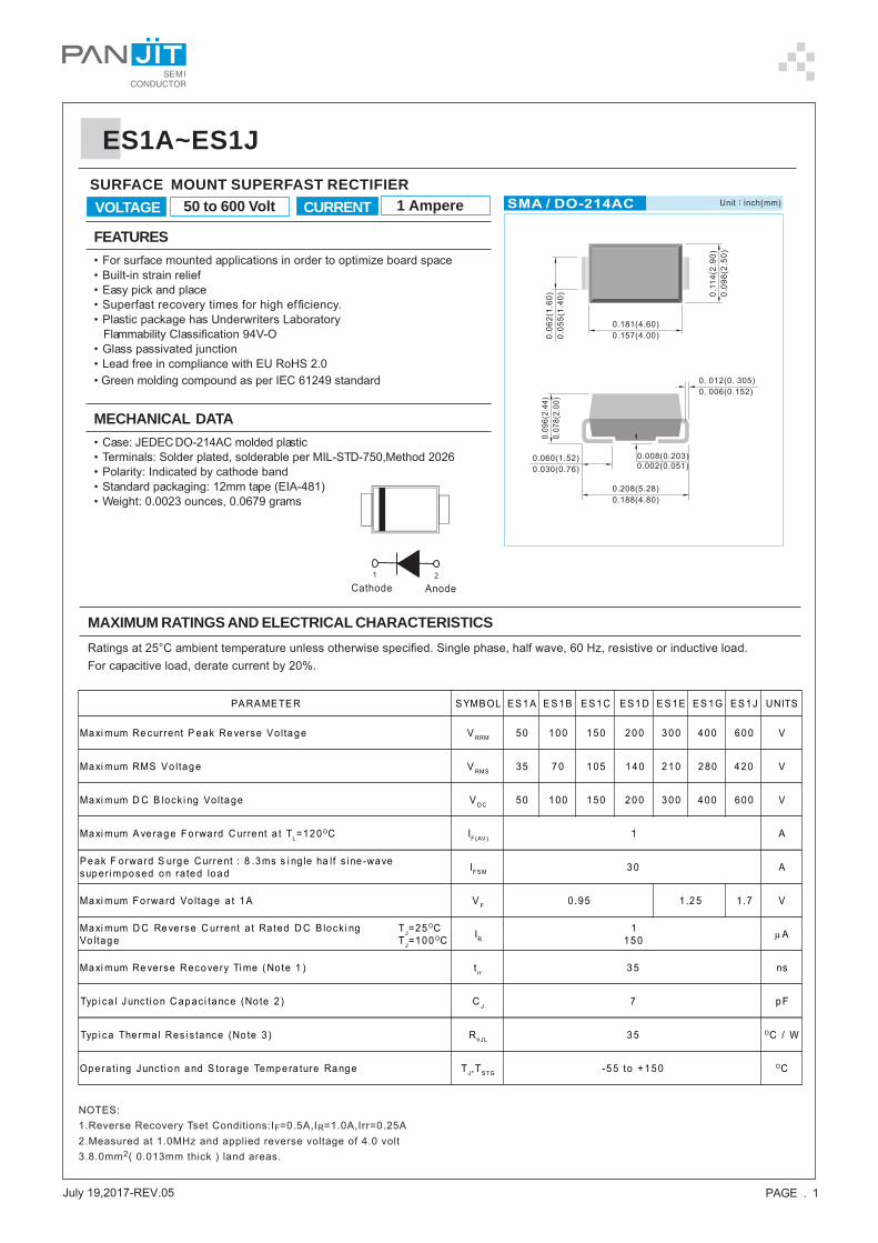
PAGE . 1 July 19,2017REV.05 ES1A~ES1J FEATURES • For surface mounted applications in order to optimize board space • Built-in strain relief • Easy pick and place • Superfast recovery times for high efficiency. • Plastic package has Underwriters Laboratory Flammability Classification 94V-O • Glass passivated junction •Lead free in compliance with EU RoHS 2.0 • Green molding compound as per IEC 61249 standard MECHANICAL DATA • Case: JEDEC DO-214AC molded plastic • Terminals: Solder plated, solderable per MIL-STD-750,Method 2026 • Polarity: Indicated by cathode band • Standard packaging: 12mm tape (EIA-481) • Weight: 0.0023 ounces, 0.0679 grams SURFACE MOUNT SUPERFAST RECTIFIER MAXIMUM RATINGS AND ELECTRICAL CHARACTERISTICS Ratings at 25°C ambient temperature unless otherwise specified. Single phase, half wave, 60 Hz, resistive or inductive load. For capacitive load, derate current by 20%. NOTES: 1.Reverse Recovery Tset Conditions:I F =0.5A,I R =1.0A,Irr=0.25A 2.Measured at 1.0MHz and applied reverse voltage of 4.0 volt 3.8.0mm 2 ( 0.013mm thick ) land areas. 50 to 600 Volt 1 Ampere CURRENT VOLTAGE 1 2 Cathode Anode PARAMETER SYMBOL ES1A ES1B ES1C ES1D ES1E ES1G ES1J UNITS Maximum Recurrent Peak Reverse Voltage V RRM 50 100 150 200 300 400 600 V Maximum RMS Voltage V RMS 35 70 105 140 210 280 420 V Maximum DC Blocking Voltage V DC 50 100 150 200 300 400 600 V Maximum Average Forward Current at T L =120 O C I F(AV) 1 A Peak Forward Surge Current : 8.3ms single half sine-wave superimposed on rated load I FSM 30 A Maximum Forward Voltage at 1A V F 0.95 1.25 1.7 V Maximum DC Reverse Current at Rated DC Blocking Voltage T J =25 O C T J =100 O C I R 1 150 μ A Maximum Reverse Recovery Time (Note 1) t rr 35 ns Typical Junction Capacitance (Note 2) C J 7 pF Typica Thermal Resistance (Note 3) R θJL 35 O C / W Operating Junction and Storage Temperature Range T J ,T STG -55 to +150 O C
Transcript of ES1A~ES1J - PANJIT International Inc. Fast Recovery/ES1A_SERIES...Maximum Reverse Recovery Time...
PAGE . 1July 19,2017REV.05
ES1A~ES1J
FEATURES• For surface mounted applications in order to optimize board space• Built-in strain relief• Easy pick and place• Superfast recovery times for high efficiency.• Plastic package has Underwriters Laboratory Flammability Classification 94V-O• Glass passivated junction• Lead free in compliance with EU RoHS 2.0• Green molding compound as per IEC 61249 standard
MECHANICAL DATA• Case: JEDEC DO-214AC molded plastic• Terminals: Solder plated, solderable per MIL-STD-750,Method 2026• Polarity: Indicated by cathode band• Standard packaging: 12mm tape (EIA-481)• Weight: 0.0023 ounces, 0.0679 grams
SURFACE MOUNT SUPERFAST RECTIFIER
MAXIMUM RATINGS AND ELECTRICAL CHARACTERISTICSRatings at 25°C ambient temperature unless otherwise specified. Single phase, half wave, 60 Hz, resistive or inductive load.For capacitive load, derate current by 20%.
NOTES:1.Reverse Recovery Tset Conditions:IF=0.5A,IR=1.0A,Irr=0.25A2.Measured at 1.0MHz and applied reverse voltage of 4.0 volt3.8.0mm2( 0.013mm thick ) land areas.
50 to 600 Volt 1 AmpereCURRENTVOLTAGE
1 2
Cathode Anode
PARAMETER SYMBOL ES1A E S1B ES1C ES1D E S1E ES 1G ES1J UNITS
Maxi mum Re current P eak Re verse Vo lta ge V RRM 50 100 150 200 300 400 600 V
Maxi mum RMS Vo ltage V RMS 35 70 105 140 210 280 420 V
Maxi mum D C B lock i ng Vo ltage V D C 50 100 150 200 300 400 600 V
Maxi mum A ve ra g e F o rward C urre nt a t TL=120 OC IF(AV ) 1 A
Peak F orwa rd S urge Current : 8 .3ms s i ng le ha lf s i ne -wavesup er i mpo sed o n ra te d lo a d IFS M 30 A
Maxi mum Fo rwa rd Vo ltage a t 1A V F 0 .95 1.25 1.7 V
Maxi mum D C Reve rse C urrent at Rated D C B lock i ngVo ltage
TJ=25 OCTJ=100 OC IR
1150 μA
Ma xi mum Re verse Recovery Ti me ( Note 1 ) t rr 35 ns
Typ i ca l J unc ti o n C ap ac i tance (No te 2 ) C J 7 p F
Typ i ca The rmal Res i s tanc e (No te 3 ) R θJL 35 OC / W
Ope ra t i ng Junc ti o n a nd S tora ge Temp e ra ture Range TJ,TS TG -5 5 to + 15 0 OC
PAGE . 2July 19,2017REV.05
ES1A~ES1J
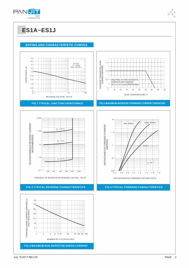
RATING AND CHARACTERISTIC CURVES
FIG.2 MAXIMUM AVERAGE FORWARD CURRENT DERATING
LEAD TEMPERATURE, CO
AV
ER
AG
EF
OR
WA
RD
RE
CIF
IED
CU
RR
EN
TA
MP
ER
ES
00
0.5
1.0
1.5
20 40 60 80 100 120 140 160 180
SINGLE PHASE, HALF-WAVE, 60Hz RESISTIVE
OR INDUCTIVE LOAD P.C.B MOUNTED
ON 0.3 x 0.3" (8.0 x 8.0 mm)COPPER PAD AREAS
FIG.1 TYPICAL JUNCTION CAPACITANCE
REVERSE VOLTAGE, VOLTS
CA
PA
CIT
AN
CE
,p
F
FIG.4 TYPICAL FORWARD CHARACTERISTICS
INSTANTANEOUS FORWARD VOLTAGE VOLTS
INS
TA
NT
AN
EO
US
FO
RW
AR
DC
UR
RE
NT,
AM
PE
RE
S
FIG.3 TYPICAL REVERSE CHARACTERISTICS
NUMBER OF CYCLES AT 60Hz
FO
RW
AR
DS
UR
GE
CU
RR
EN
T,A
MP
ER
ES
pk
(H
AL
F-S
ING
WA
VE
)
FIG.5 MAXIMUM NON-REPEITIVE SURGE CURRENT
40 60 80 1001 2 4 6 8 10 20
5
20
15
10
30
25
35
0.1 1 10 100
Tj= 25 C
f= 1 .0MHz
Vsig = 50mVp -p
O
12
0
2.0
4.0
6.0
8.0
10
14
16
18
1.0
.1
.01
.001
0.4 0.6 0.8 1.0 1.2 1 1 1. . .4 6 8
T = 25 CJ
O
10
600V
300-400V50-200V
PERCENT OF RATED PEAK INVERSE VOLTGE, VOLTS
INV
ST
AN
TA
NE
OU
SR
EV
ER
SE
CU
RR
EN
T,
MIC
RO
AM
PE
RE
S
1000
100
10
1.0
0.120 40 60 80 100 120
T = 75 CJ
O
T = 25 CJ
O
T = 125 CJ
O
PAGE . 3July 19,2017REV.05
ES1A~ES1J
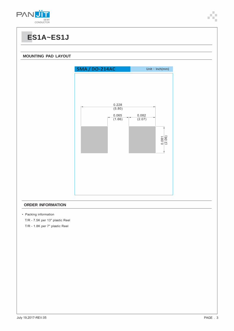
MOUNTING PAD LAYOUT
ORDER INFORMATION
• Packing information
T/R - 7.5K per 13" plastic Reel
T/R - 1.8K per 7" plastic Reel
PAGE . 4July 19,2017REV.05
ES1A~ES1J
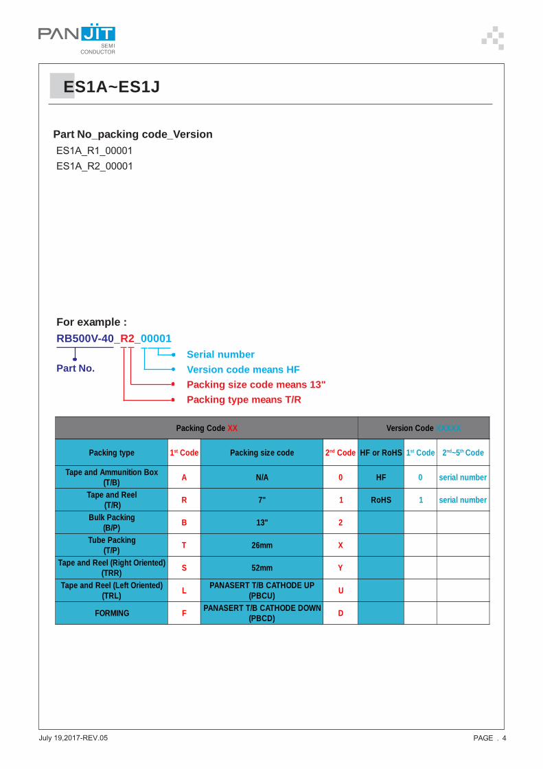
Part No_packing code_Version ES1A_R1_00001 ES1A_R2_00001
For example :RB500V-40_R2_00001
Part No.Serial numberVersion code means HFPacking size code means 13"Packing type means T/R
Packing Code XX Version Code XXXXX
Packing type 1st Code Packing size code 2nd Code HF or RoHS 1st Code 2nd~5th Code
Tape and Ammunition Box(T/B) A N/A 0 HF 0 serial number
Tape and Reel (T/R) R 7" 1 RoHS 1 serial number
Bulk Packing(B/P) B 13" 2
Tube Packing(T/P) T 26mm X
Tape and Reel (Right Oriented)(TRR) S 52mm Y
Tape and Reel (Left Oriented)(TRL) L PANASERT T/B CATHODE UP
(PBCU) U
FORMING F PANASERT T/B CATHODE DOWN(PBCD) D
PAGE . 5July 19,2017REV.05
ES1A~ES1J
Disclaimer
• Reproducing and modifying information of the document is prohibited without permissionfrom Panjit International Inc..
• Panjit International Inc. reserves the rights to make changes of the content herein thedocument anytime without notification. Please refer to our website for the latestdocument.
Panjit International Inc. disclaims any and all liability arising out of the application or use ofany product including damages incidentally and consequentially occurred.
• Panjit International Inc. does not assume any and all implied warranties, including warrantiesof fitness for particular purpose, non-infringement and merchantability.
• Applications shown on the herein document are examples of standard use and operation.Customers are responsible in comprehending the suitable use in particular applications.Panjit International Inc. makes no representation or warranty that such applications will besuitable for the specified use without further testing or modification.
• The products shown herein are not designed and authorized for equipments requiring highlevel of reliability or relating to human life and for any applications concerning life-savingor life-sustaining, such as medical instruments, transportation equipment, aerospacemachinery et cetera. Customers using or selling these products for use in such applicationsdo so at their own risk and agree to fully indemnify Panjit International Inc. for any damagesresulting from such improper use or sale.
•
• Since Panjit uses lot number as the tracking base, please provide the lot number for trackingwhen complaining.