DTC and Non Linear Vector Control Strategies applied to ... · 1.5 2 2.5 3 ω(rad/s) P m (Mw) P m...
10
DTC and Non Linear Vector Control Strategies applied to the DFIG operated at Variable Speed JIHÈNE BEN ALAYA (1,3) , ADEL KHEDHER (2,4) , MOHAMED FAOUZI MIMOUNI (1,5) Réseaux et Machines Electrique (RME) (1) , Renewable Energy and Electric Vehicles (RELEV) (2) High School of Sciences & Technology of Hammem Sousse (ESSTHS) (3) , Rue Lamine Abassi, 4011 Hammem Sousse-TUNISIA. National Engineering School of Sousse (ENISO) (4) , Route de Ceinture Sahloul,Cité Hammam Maarouf, 4054 Sousse-TUNISIA. National Engineering School of Monastir (ENIM) (5) , Cité Ibn Aljazzar, 5000 Monastir-TUNISIA. [email protected] [email protected] [email protected] Abstract: - We present in this paper the modeling and control designs for a variable-speed constant-frequency wind energy conversion system using double fed induction generator. The aim of this paper is to design and compare two distinct control strategies to control the rotor side power converter. Firstly, a nonlinear vector control strategy using the second Lyapunov approach is developed. Secondly, a direct torque control strategy, constructed around two hysteresis controllers that allow flux and torque regulation, is presented. Simulation results have shown good performances of the system under these proposed control strategies. Compared to nonlinear vector control strategy, the direct torque control approach presents best performances. Key-Words: - Wind drive - Double fed induction generator - Direct torque control - Nonlinear vector control - Lyapunov approach. 1 Introduction To produce electrical energy using a wind energy conversion system (WECS), various control strategies have been developed in the literature [1- 10]. All this strategies have the goal to bring down the cost of electrical energy produced by the WECS and to converge the system for operating at unity power factor. The field oriented control strategy (FOC) has attracted much attention in the past few decades but it suffers from the problem of the machine parameters variations, which comes to compromise the robustness of the control device [6]. Indeed, the PI regulators coefficients used in FOC strategy, are directly calculated according to the parameters machine what entrain a poor robustness vs parameters variations [2,6,8,9]. The aim of this paper is to present, discuss and compare two control strategies, a non linear vector control (NLVC) and a direct torque control (DTC), for double fed induction generator (DFIG) driven by wind turbines. The NLVC is based on the second approach of Lyapunov theory which rests on the definition of positive definite function V whose convergence towards zero generate the convergence of the state of the system towards its equilibrium. In this study, the definition of the candidate function is based on the minimization of the energy criterion. The DTC strategy controls directly the electromagnetic torque and flux by selecting voltage vectors from a look- up-table. This approach uses two bang-bang hysteresis controllers without current limiter. This approach is penalized by the electromagnetic torque noises and the high switching frequency. However, it’s characterized by its stability vs parameters variations. For both proposed control strategies, we will maximize the energy captured from the wind turbine and injected to the grid. In this proposed structure, the DFIG will be connected to a rural grid directly by the stator and through a back to back converter by the rotor. This structure has the advantage of using power converter rated for approximately 25% of the total exchanged power, which makes this solution more suitable for variable speed wind turbines [8]. This paper is organized as follows: in the second section, we present the model of the DFIG and of the wind turbine. Third section presents the control strategies of the rotor side converter. Firstly, we propose a nonlinear vector control of DFIG based on the second approach of Lyapunov. Then, the DTC principle is developed. Fourth section, studies WSEAS TRANSACTIONS on ENVIRONMENT and DEVELOPMENT Jihene Ben Alaya, Adel Khedher, Mohamed Faouzi Mimouni ISSN: 1790-5079 744 Issue 11, Volume 6, November 2010
Transcript of DTC and Non Linear Vector Control Strategies applied to ... · 1.5 2 2.5 3 ω(rad/s) P m (Mw) P m...
DTC and Non Linear Vector Control Strategies applied to the DFIG operated at Variable Speed
JIHÈNE BEN ALAYA(1,3) , ADEL KHEDHER(2,4) , MOHAMED FAOUZI MIMOUNI(1,5)
Réseaux et Machines Electrique (RME) (1), Renewable Energy and Electric Vehicles (RELEV) (2)
High School of Sciences & Technology of Hammem Sousse (ESSTHS) (3), Rue Lamine Abassi, 4011 Hammem Sousse-TUNISIA.
National Engineering School of Sousse (ENISO) (4), Route de Ceinture Sahloul,Cité Hammam Maarouf, 4054 Sousse-TUNISIA.
National Engineering School of Monastir (ENIM) (5), Cité Ibn Aljazzar, 5000 Monastir-TUNISIA.
[email protected] [email protected] [email protected] Abstract: - We present in this paper the modeling and control designs for a variable-speed constant-frequency wind energy conversion system using double fed induction generator. The aim of this paper is to design and compare two distinct control strategies to control the rotor side power converter. Firstly, a nonlinear vector control strategy using the second Lyapunov approach is developed. Secondly, a direct torque control strategy, constructed around two hysteresis controllers that allow flux and torque regulation, is presented. Simulation results have shown good performances of the system under these proposed control strategies. Compared to nonlinear vector control strategy, the direct torque control approach presents best performances. Key-Words: - Wind drive - Double fed induction generator - Direct torque control - Nonlinear vector control -Lyapunov approach. 1 Introduction To produce electrical energy using a wind energy conversion system (WECS), various control strategies have been developed in the literature [1-10]. All this strategies have the goal to bring down the cost of electrical energy produced by the WECS and to converge the system for operating at unity power factor. The field oriented control strategy (FOC) has attracted much attention in the past few decades but it suffers from the problem of the machine parameters variations, which comes to compromise the robustness of the control device [6]. Indeed, the PI regulators coefficients used in FOC strategy, are directly calculated according to the parameters machine what entrain a poor robustness vs parameters variations [2,6,8,9].
The aim of this paper is to present, discuss and compare two control strategies, a non linear vector control (NLVC) and a direct torque control (DTC), for double fed induction generator (DFIG) driven by wind turbines.
The NLVC is based on the second approach of Lyapunov theory which rests on the definition of positive definite function V whose convergence towards zero generate the convergence of the state of the system towards its equilibrium. In this study,
the definition of the candidate function is based on the minimization of the energy criterion. The DTC strategy controls directly the electromagnetic torque and flux by selecting voltage vectors from a look-up-table. This approach uses two bang-bang hysteresis controllers without current limiter. This approach is penalized by the electromagnetic torque noises and the high switching frequency. However, it’s characterized by its stability vs parameters variations. For both proposed control strategies, we will maximize the energy captured from the wind turbine and injected to the grid.
In this proposed structure, the DFIG will be connected to a rural grid directly by the stator and through a back to back converter by the rotor. This structure has the advantage of using power converter rated for approximately 25% of the total exchanged power, which makes this solution more suitable for variable speed wind turbines [8].
This paper is organized as follows: in the second section, we present the model of the DFIG and of the wind turbine. Third section presents the control strategies of the rotor side converter. Firstly, we propose a nonlinear vector control of DFIG based on the second approach of Lyapunov. Then, the DTC principle is developed. Fourth section, studies
WSEAS TRANSACTIONS on ENVIRONMENT and DEVELOPMENTJihene Ben Alaya, Adel Khedher, Mohamed Faouzi Mimouni
ISSN: 1790-5079 744 Issue 11, Volume 6, November 2010
the control of electrical system in the grid side. Simulation results are presented and discussed in the fifth section and we finish by a conclusion.
2 Double fed induction generator model
In complex notation, the DFIG mechanical and electrical equations are derived from Park model expressed in a reference frame d-q rotating at synchronous speed ωs as follows [8].
2
- -
- -
( )
sss s sr r ss s sr r
rrs s rr r sr s rr r
t tm em
d i a i a i b v b vdtd i a i a i b v b vdt
J TdJ f Tm dt G
ω ω
⎧ = + +⎪⎪⎪ = +⎨⎪⎪
+ + = −⎪⎩
(1)
With: 21 ( - )gs
sss s r
Ma j
L Lωω
στ σ σ= +
( - )sr g ss r s
M Ma jL L
ω ωσ τ σ
= +
( - )rs s gr s r
M Ma jL L
ω ωσ τ σ
= + ;
21 ( - )g srr
r s r
Ma jL L
ω ωστ σ σ
= +
1ss
s
bLσ
= ; srs r
MbL Lσ
= ; 1
rrr
bLσ
=
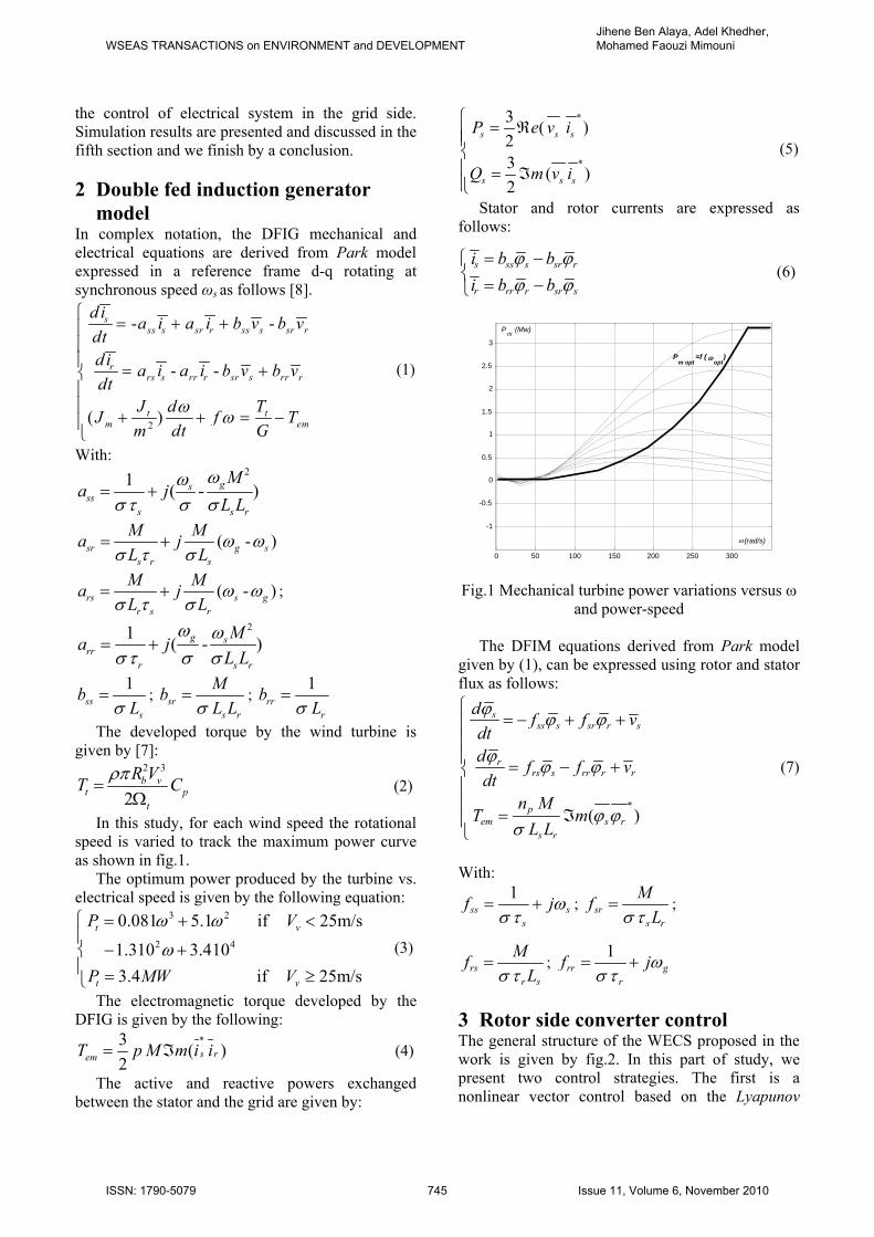
The developed torque by the wind turbine is given by [7]:
2 3
2b v
t pt
R VT Cρπ=
Ω (2)
In this study, for each wind speed the rotational speed is varied to track the maximum power curve as shown in fig.1.
The optimum power produced by the turbine vs. electrical speed is given by the following equation:
3 2
2 4
0.081 5.1 if 25m/s
1.310 3.4103.4 if 25m/s
t v
t v
P V
P MW V
ω ω
ω
⎧ = + <⎪
− +⎨⎪ = ≥⎩
(3)
The electromagnetic torque developed by the DFIG is given by the following:
*3 ( )2
s remT p M m i i= ℑ (4)
The active and reactive powers exchanged between the stator and the grid are given by:
*
*
3 ( )23 ( )2
s s s
s s s
P e v i
Q m v i
⎧ = ℜ⎪⎪⎨⎪ = ℑ⎪⎩
(5)
Stator and rotor currents are expressed as follows:
s ss s sr r
r rr r sr s
i b bi b b
ϕ ϕϕ ϕ
= −⎧⎨
= −⎩ (6)
Fig.1 Mechanical turbine power variations versus ω
and power-speed
The DFIM equations derived from Park model given by (1), can be expressed using rotor and stator flux as follows:
*( )
sss s sr r s
rrs s rr r r
pem s r
s r
d f f vdtd f f vdt
n MT m
L L
ϕ ϕ ϕ
ϕ ϕ ϕ
ϕ ϕσ
⎧= − + +⎪
⎪⎪ = − +⎨⎪⎪
= ℑ⎪⎩
(7)
With:
1ss s
s
f jωσ τ
= + ; srs r
MfLσ τ
= ;
rsr s
MfLσ τ
= ; 1
rr gr
f jωσ τ
= +
3 Rotor side converter control The general structure of the WECS proposed in the work is given by fig.2. In this part of study, we present two control strategies. The first is a nonlinear vector control based on the Lyapunov
0 50 100 150 200 250 300
-1
-0.5
0
0.5
1
1.5
2
2.5
3
ω(rad/s)
Pm
(Mw)
P m opt =f ( ω
opt)
WSEAS TRANSACTIONS on ENVIRONMENT and DEVELOPMENTJihene Ben Alaya, Adel Khedher, Mohamed Faouzi Mimouni
ISSN: 1790-5079 745 Issue 11, Volume 6, November 2010
stability theory. The second is the DTC control strategy.
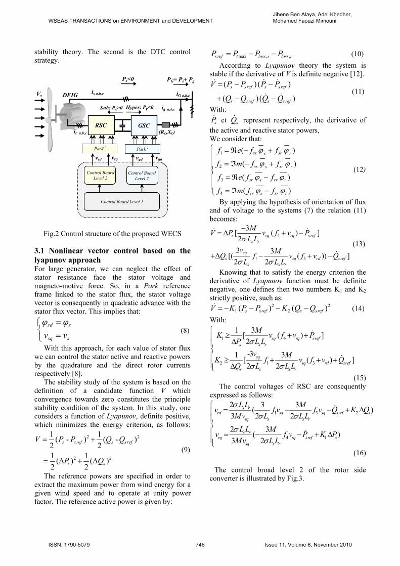
Fig.2 Control structure of the proposed WECS
3.1 Nonlinear vector control based on the lyapunov approach For large generator, we can neglect the effect of stator resistance face the stator voltage and magneto-motive force. So, in a Park reference frame linked to the stator flux, the stator voltage vector is consequently in quadratic advance with the stator flux vector. This implies that:
sd s
sq sv vϕ ϕ=⎧⎨ =⎩
(8)
With this approach, for each value of stator flux we can control the stator active and reactive powers by the quadrature and the direct rotor currents respectively [8].
The stability study of the system is based on the definition of a candidate function V which convergence towards zero constitutes the principle stability condition of the system. In this study, one considers a function of Lyapunov, definite positive, which minimizes the energy criterion, as follows:
2 2
2 2
1 1( - ) ( - )2 21 1( ) ( )2 2
s s ref s s ref
s s
V P P Q Q
P Q
= +
= Δ + Δ (9)
The reference powers are specified in order to extract the maximum power from wind energy for a given wind speed and to operate at unity power factor. The reference active power is given by:
max , ,s ref t loss s loss rP P P P= − − (10) According to Lyapunov theory the system is
stable if the derivative of V is definite negative [12]. ( ) ( )
( ) ( )s s ref s s ref
s s ref s s ref
V P P P P
Q Q Q Q
= − −
+ − −
& & &
& & (11)
With: sP& et sQ& represent respectively, the derivative of
the active and reactive stator powers, We consider that:
1
2
3
4
( )
( )
( )
( )
ss srs r
ss srs r
sr s rr r
rs s rr r
f e f f
f m f f
f e f f
f m f f
ϕ ϕ
ϕ ϕ
ϕ ϕ
ϕ ϕ
⎧ = ℜ − +⎪
= ℑ − +⎪⎨
= ℜ −⎪⎪ = ℑ −⎩
(12)
By applying the hypothesis of orientation of flux and of voltage to the systems (7) the relation (11) becomes:
4
1 3
3[ ( ) ]23 3[( ( )) ]
2 2
s sq rq s refs r
sqs sq rd s ref
s s r
MV P v f v PL L
v MQ f v f v QL L L
σ
σ σ
−= Δ + −
+Δ − + −
& &
& (13)
Knowing that to satisfy the energy criterion the derivative of Lyapunov function must be definite negative, one defines then two numbers K1 and K2 strictly positive, such as:
2 21 2( ) ( )s s ref s s refV K P P K Q Q= − − − −& (14)
With:
1 4
2 1 3
1 3[ ( ) ]2-31 3[ ( ) ]2 2
sq rq srefs s r
sqsq rd sref
s s s r
MK v f v PP L L
v MK f v f v QQ L L L
σ
σ σ
⎧ ≥ + +⎪ Δ⎪⎨⎪ ≥ + + +⎪ Δ⎩
&
&
(15) The control voltages of RSC are consequently
expressed as follows:
1 3 2
4 1
2 3 3( )3 2 2
2 3( )3 2
s rrd sq sq sref s
sq s s r
s rrq sq sref s
sq s r
L L Mv f v f v Q K QMv L L L
L L Mv f v P K PMv L L
σσ σ
σσ
⎧ = − − + Δ⎪⎪⎨⎪ = − − + Δ⎪⎩
&
&
(16)
The control broad level 2 of the rotor side converter is illustrated by Fig.3.
Vv is a,b,c iG a,b,c
GSC (RL,XL)
ig a,b,c
ir a,b,c
RSC
Control Board Level 2
vrd vrq
Park-1
Control Board Level 2
vgd vgq
Park-1
Control Board Level 1
Sub: Pg>0 Hyper: Pg<0
Ps<0 PG= Ps+ Pg
DFIG
WSEAS TRANSACTIONS on ENVIRONMENT and DEVELOPMENTJihene Ben Alaya, Adel Khedher, Mohamed Faouzi Mimouni
ISSN: 1790-5079 746 Issue 11, Volume 6, November 2010
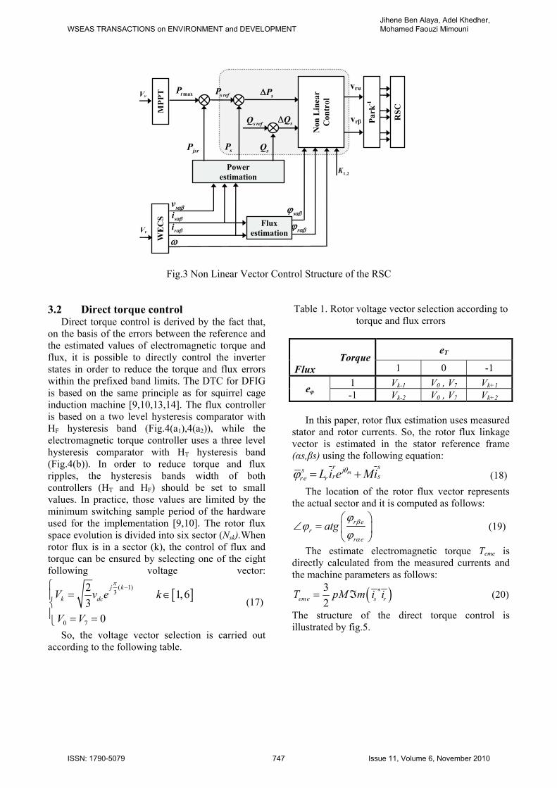
Fig.3 Non Linear Vector Control Structure of the RSC
3.2 Direct torque control
Direct torque control is derived by the fact that, on the basis of the errors between the reference and the estimated values of electromagnetic torque and flux, it is possible to directly control the inverter states in order to reduce the torque and flux errors within the prefixed band limits. The DTC for DFIG is based on the same principle as for squirrel cage induction machine [9,10,13,14]. The flux controller is based on a two level hysteresis comparator with HF hysteresis band (Fig.4(a1),4(a2)), while the electromagnetic torque controller uses a three level hysteresis comparator with HT hysteresis band (Fig.4(b)). In order to reduce torque and flux ripples, the hysteresis bands width of both controllers (HT and HF) should be set to small values. In practice, those values are limited by the minimum switching sample period of the hardware used for the implementation [9,10]. The rotor flux space evolution is divided into six sector (Nsk).When rotor flux is in a sector (k), the control of flux and torque can be ensured by selecting one of the eight following voltage vector:
[ ]( 1)
3
0 7
2 1,63
0
j k
k dcV v e k
V V
π−⎧
= ∈⎪⎨⎪ = =⎩
(17)
So, the voltage vector selection is carried out according to the following table.
Table 1. Rotor voltage vector selection according to torque and flux errors
TorqueFlux
eT
1 0 -1
eφ 1 Vk-1 V0 , V7 Vk+1 -1 Vk-2 V0 , V7 Vk+2
In this paper, rotor flux estimation uses measured
stator and rotor currents. So, the rotor flux linkage vector is estimated in the stator reference frame (αs,βs) using the following equation:
mr ss jr sre rL i e Miθϕ = + (18)
The location of the rotor flux vector represents the actual sector and it is computed as follows:
r er
r e
atg β
α
ϕϕ
ϕ⎛ ⎞
∠ = ⎜ ⎟⎝ ⎠
(19)
The estimate electromagnetic torque Teme is directly calculated from the measured currents and the machine parameters as follows:
( )*32eme s rT pM m i i= ℑ (20)
The structure of the direct torque control is illustrated by fig.5.
vrα
vrβ
sP
Vv
RSC
Park
-1
Non
Lin
ear
C
ontr
ol maxtP
Power estimation
sv αβ
si αβ
ri αβ rαβϕ
sαβϕ
jsrP
MPP
T
Vv s refP sPΔ
s refQ sQΔ
sQ
ω
1,2K
Flux estimationW
EC
S
WSEAS TRANSACTIONS on ENVIRONMENT and DEVELOPMENTJihene Ben Alaya, Adel Khedher, Mohamed Faouzi Mimouni
ISSN: 1790-5079 747 Issue 11, Volume 6, November 2010
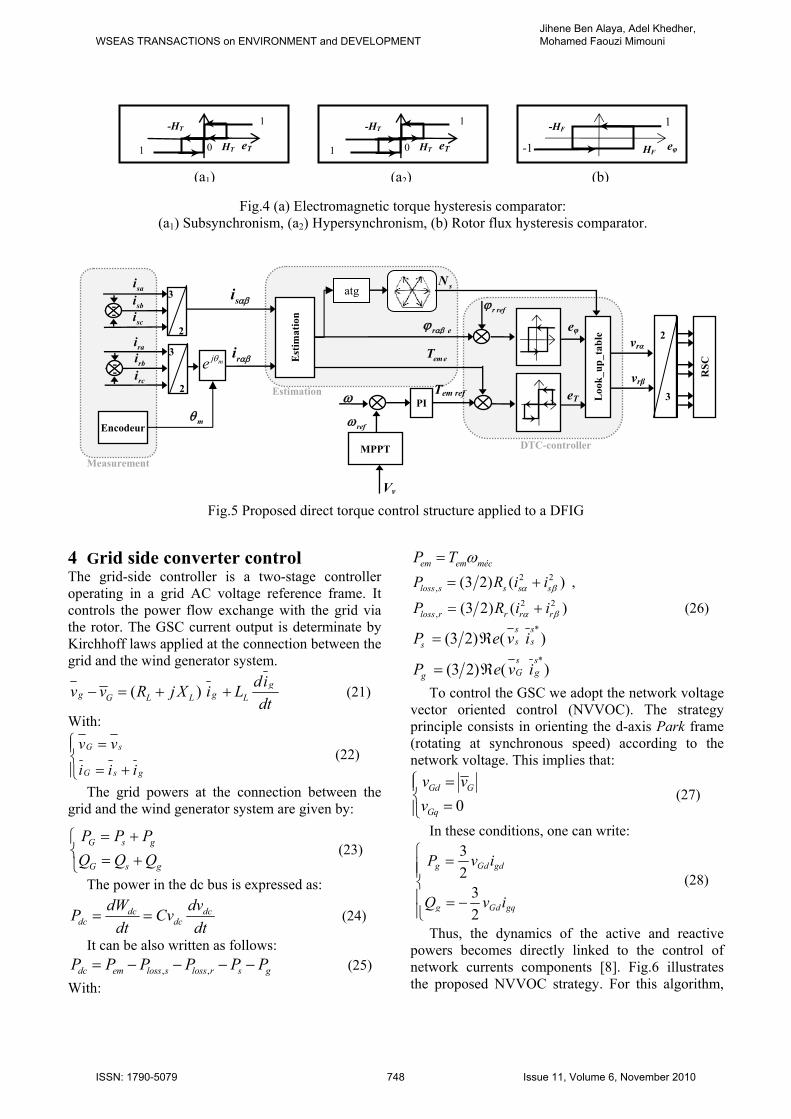
Fig.5 Proposed direct torque control structure applied to a DFIG
4 Grid side converter control The grid-side controller is a two-stage controller operating in a grid AC voltage reference frame. It controls the power flow exchange with the grid via the rotor. The GSC current output is determinate by Kirchhoff laws applied at the connection between the grid and the wind generator system.
( ) gg gG L L L
div v R j X i Ldt
− = + +
(21)
With: G s
G s g
v v
i i i
⎧ =⎪⎨
= +⎪⎩ (22)
The grid powers at the connection between the grid and the wind generator system are given by:
G s g
G s g
P P PQ Q Q
= +⎧⎨ = +⎩
(23)
The power in the dc bus is expressed as:
dc dcdc dc
dW dvP Cvdt dt
= = (24)
It can be also written as follows: , ,dc em loss s loss r s gP P P P P P= − − − − (25)
With:
em em mécP T ω=
2 2, (3 2) ( )loss s s s sP R i iα β= + ,
2 2, (3 2) ( )loss r r r rP R i iα β= + (26)
*(3 2) ( )
s ss ssP e v i= ℜ
*(3 2) ( )
s sG ggP e v i= ℜ
To control the GSC we adopt the network voltage vector oriented control (NVVOC). The strategy principle consists in orienting the d-axis Park frame (rotating at synchronous speed) according to the network voltage. This implies that:
0Gd G
Gq
v vv⎧ =⎪⎨ =⎪⎩
(27)
In these conditions, one can write:
32
32
g Gd gd
g Gd gq
P v i
Q v i
⎧ =⎪⎪⎨⎪ = −⎪⎩
(28)
Thus, the dynamics of the active and reactive powers becomes directly linked to the control of network currents components [8]. Fig.6 illustrates the proposed NVVOC strategy. For this algorithm,
2 3
vrα
vrβ
Tem ref PI
em eT
ω
eφ
eT
RSC
Loo
k_up
_tab
le
refω
MPPT
r eαβϕ
Vv
r refϕ si αβ sai
3 2
sci sbi
ri αβ rai
3 2
rci rbi mje θ
Encodeur
Est
imat
ion
sN atg
Measurement
mθ
Estimation
DTC-controller
- -
- -
0 eT
-HT
HT 1
1
0 eT
-HT
HT
1
1 -1
1
eφ
-HF
HF
(a1) (a2) (b)
Fig.4 (a) Electromagnetic torque hysteresis comparator: (a1) Subsynchronism, (a2) Hypersynchronism, (b) Rotor flux hysteresis comparator.
WSEAS TRANSACTIONS on ENVIRONMENT and DEVELOPMENTJihene Ben Alaya, Adel Khedher, Mohamed Faouzi Mimouni
ISSN: 1790-5079 748 Issue 11, Volume 6, November 2010
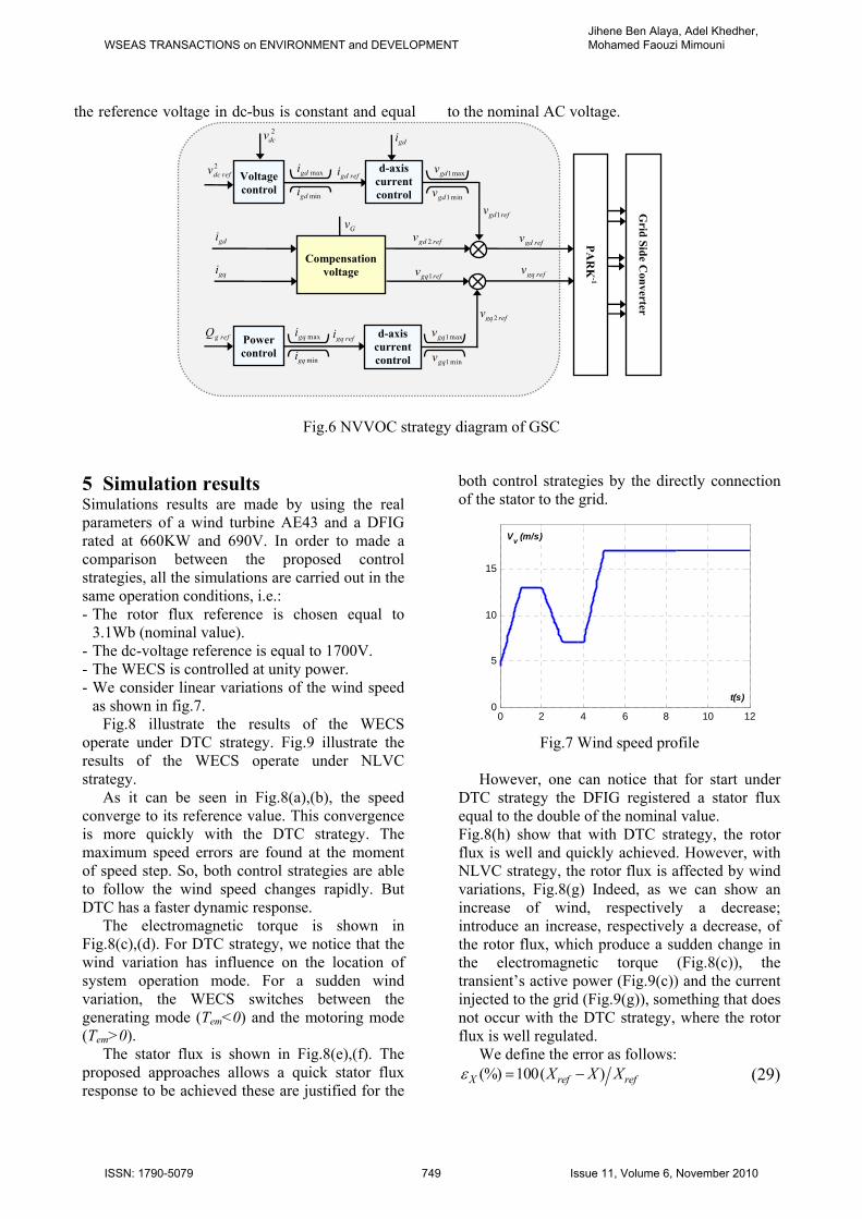
the reference voltage in dc-bus is constant and equal to the nominal AC voltage.
Fig.6 NVVOC strategy diagram of GSC
5 Simulation results Simulations results are made by using the real parameters of a wind turbine AE43 and a DFIG rated at 660KW and 690V. In order to made a comparison between the proposed control strategies, all the simulations are carried out in the same operation conditions, i.e.: - The rotor flux reference is chosen equal to
3.1Wb (nominal value). - The dc-voltage reference is equal to 1700V. - The WECS is controlled at unity power. - We consider linear variations of the wind speed
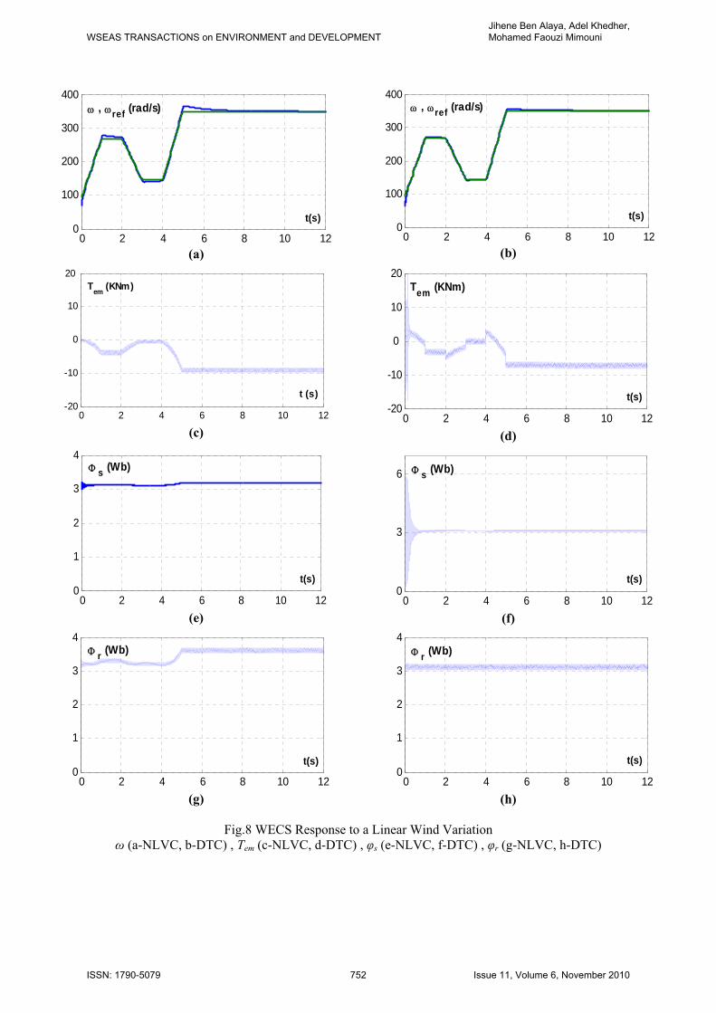
as shown in fig.7. Fig.8 illustrate the results of the WECS
operate under DTC strategy. Fig.9 illustrate the results of the WECS operate under NLVC strategy.
As it can be seen in Fig.8(a),(b), the speed converge to its reference value. This convergence is more quickly with the DTC strategy. The maximum speed errors are found at the moment of speed step. So, both control strategies are able to follow the wind speed changes rapidly. But DTC has a faster dynamic response.
The electromagnetic torque is shown in Fig.8(c),(d). For DTC strategy, we notice that the wind variation has influence on the location of system operation mode. For a sudden wind variation, the WECS switches between the generating mode (Tem<0) and the motoring mode (Tem>0).
The stator flux is shown in Fig.8(e),(f). The proposed approaches allows a quick stator flux response to be achieved these are justified for the
both control strategies by the directly connection of the stator to the grid.
Fig.7 Wind speed profile
However, one can notice that for start under
DTC strategy the DFIG registered a stator flux equal to the double of the nominal value. Fig.8(h) show that with DTC strategy, the rotor flux is well and quickly achieved. However, with NLVC strategy, the rotor flux is affected by wind variations, Fig.8(g) Indeed, as we can show an increase of wind, respectively a decrease; introduce an increase, respectively a decrease, of the rotor flux, which produce a sudden change in the electromagnetic torque (Fig.8(c)), the transient’s active power (Fig.9(c)) and the current injected to the grid (Fig.9(g)), something that does not occur with the DTC strategy, where the rotor flux is well regulated.
We define the error as follows: (%) 100( )X ref refX X Xε = −
(29)
0 2 4 6 8 10 120
5
10
15
t(s)
Vv (m/s)
gdi
gqi
Gv
gqi
Compensation
voltage
2gd refv
2gq refv
1gq refv
gd refv
gq refv
1 maxgqv
1 mingqv
Grid Side C
onverter 1gd refv
gd refi2dc refv
Voltage control
mingdi
maxgdi 1maxgdv d-axis current control 1 mingdv
PAR
K-1
gq refi
mingqi
maxgqiGv
g refQ
Power control
d-axis current control
2dcv
gdi
WSEAS TRANSACTIONS on ENVIRONMENT and DEVELOPMENTJihene Ben Alaya, Adel Khedher, Mohamed Faouzi Mimouni
ISSN: 1790-5079 749 Issue 11, Volume 6, November 2010
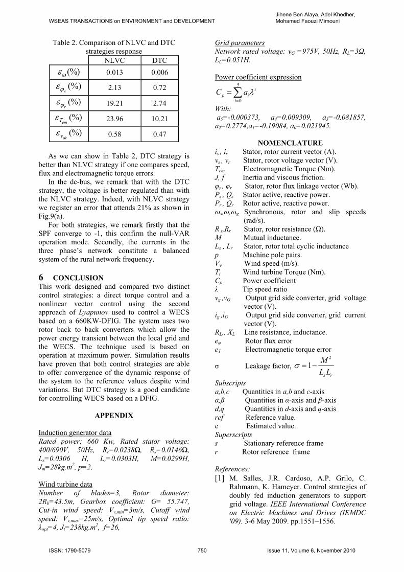
Table 2. Comparison of NLVC and DTC strategies response
NLVC DTC (%)ωε 0.013 0.006
(%)sϕε 2.13 0.72
(%)rϕε 19.21 2.74
(%)emTε 23.96 10.21
(%)dcvε 0.58 0.47
As we can show in Table 2, DTC strategy is
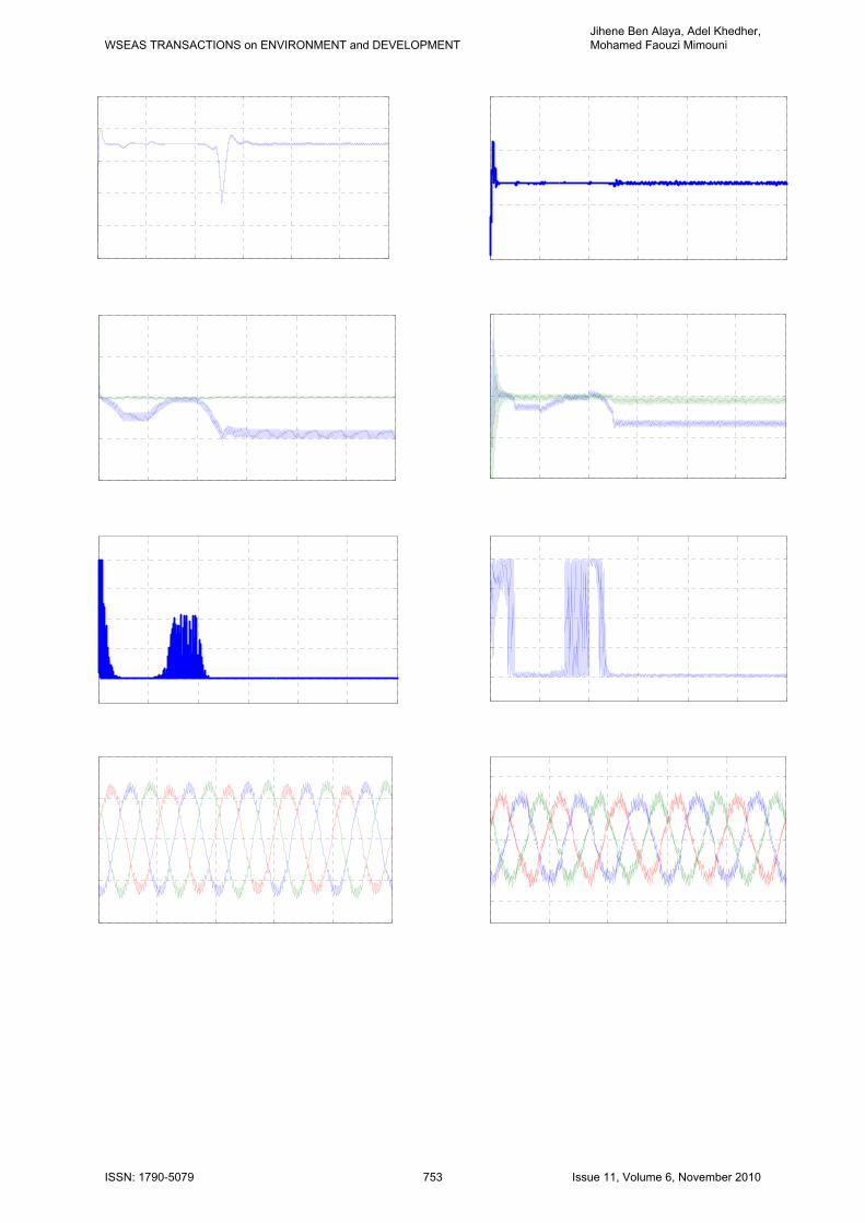
better than NLVC strategy if one compares speed, flux and electromagnetic torque errors.
In the dc-bus, we remark that with the DTC strategy, the voltage is better regulated than with the NLVC strategy. Indeed, with NLVC strategy we register an error that attends 21% as shown in Fig.9(a).
For both strategies, we remark firstly that the SPF converge to -1, this confirm the null-VAR operation mode. Secondly, the currents in the three phase’s network constitute a balanced system of the rural network frequency.
6 CONCLUSION This work designed and compared two distinct control strategies: a direct torque control and a nonlinear vector control using the second approach of Lyapunov used to control a WECS based on a 660KW-DFIG. The system uses two rotor back to back converters which allow the power energy transient between the local grid and the WECS. The technique used is based on operation at maximum power. Simulation results have proven that both control strategies are able to offer convergence of the dynamic response of the system to the reference values despite wind variations. But DTC strategy is a good candidate for controlling WECS based on a DFIG.
APPENDIX Induction generator data Rated power: 660 Kw, Rated stator voltage: 400/690V, 50Hz, Rr=0.0238Ω, Rs=0.0146Ω, Ls=0.0306 H, Lr=0.0303H, M=0.0299H, Jm=28kg.m2, p=2, Wind turbine data Number of blades=3, Rotor diameter: 2Rb=43.5m, Gearbox coefficient: G= 55.747, Cut-in wind speed: Vv,min=3m/s, Cutoff wind speed: Vv,max=25m/s, Optimal tip speed ratio: λopt=4, Jt=238kg.m2, f=26,
Grid parameters Network rated voltage: vG =975V, 50Hz, RL=3Ω, LL=0.051H. Power coefficient expression
5
0
ip i
i
C a λ=
= ∑
With: a5=-0.000373, a4=0.009309, a3=-0.081857, a2=0.2774,a1=-0.19084, a0=0.021945.
NOMENCLATURE is , ir Stator, rotor current vector (A). vs , vr Stator, rotor voltage vector (V). Tem Electromagnetic Torque (Nm). J, f Inertia and viscous friction. φs , φr Stator, rotor flux linkage vector (Wb). Ps , Qs Stator active, reactive power. Pr , Qr Rotor active, reactive power. ωs,ω,ωg Synchronous, rotor and slip speeds
(rad/s). R s,Rr Stator, rotor resistance (Ω). M Mutual inductance. Ls , Lr Stator, rotor total cyclic inductance p Machine pole pairs. Vv Wind speed (m/s). Tt Wind turbine Torque (Nm). Cp Power coefficient λ Tip speed ratio vg ,vG Output grid side converter, grid voltage
vector (V). ig ,iG Output grid side converter, grid current
vector (V). RL,, XL Line resistance, inductance. eφ Rotor flux error eT Electromagnetic torque error
σ Leakage factor, 2
1s r
ML L
σ = −
Subscripts a,b,c Quantities in a,b and c-axis α,β Quantities in α-axis and β-axis d,q Quantities in d-axis and q-axis ref Reference value. e Estimated value. Superscripts s Stationary reference frame r Rotor reference frame References: [1] M. Salles, J.R. Cardoso, A.P. Grilo, C.
Rahmann, K. Hameyer. Control strategies of doubly fed induction generators to support grid voltage. IEEE International Conference on Electric Machines and Drives (IEMDC '09). 3-6 May 2009. pp.1551–1556.
WSEAS TRANSACTIONS on ENVIRONMENT and DEVELOPMENTJihene Ben Alaya, Adel Khedher, Mohamed Faouzi Mimouni
ISSN: 1790-5079 750 Issue 11, Volume 6, November 2010
[2] F. Bonnet, P.E. Vidal, M. Pietrzak-David. Dual Direct Torque Control of Doubly Fed Induction Machine. IEEE Trans. Industrial Electronics. Vol.54, No.5. October 2007. pp. 2482-2490.
[3] A. Tapia, G. Tapia, J.X. Ostolaza, J.R. Saenz. Modeling and control of a wind turbine driven doubly fed induction generator. IEEE Trans. Energy Conversion. Vol.18, Issue 2. June 2003. pp. 194–204.
[4] S. Drid, Med S. Nait-Said, A. Makouf, Med Tadjine. Doubly Fed Induction Generator Modeling and Scalar Controlled for Supplying an Isolated Site. Journal of Electrical Systems. Vol.2, Issue 2. 2006. pp. 103-115.
[5] L. Xu, P. Cartwright. Direct active and reactive power control of DFIG for wind energy generation. IEEE Trans. Energy Conversion. Vol.21, No.3. September 2006. pp. 750–758.
[6] C. Belfedal, S. Moreau, G. Champenois, T. Allaoui, M. Denai. Comparison of PI and Direct Power Control with SVM of Doubly Fed Induction Generator. Journal of Electrical and Electronics Engineering. Vol.8, No.2. 2008. pp. 633-641.
[7] K.C. Wong, S.L. Ho, K.W.E. Cheng. Direct control algorithm for doubly fed induction generators in weak grids. Electric Power Applications, IET. Vol.3, Issue 4. July 2009. pp. 371–380.
[8] J. Ben Alaya, A. Khedher, M.F. Mimouni. Variable Speed Vector Control Strategy of the Double Fed Induction Generator Integrated in Electrical Grid. International Conference on Ecologic Vehicles and
Renewable Energy (EVER’08), Monaco, France. March 2008.
[9] A. Khedher, M.F. Mimouni. Sensorless-adaptive DTC of double star induction motor. Journal of Energy Conversion and Management. Issue 51. December 2010. pp. 2878–2892.
[10] J. Ben Alaya, A. Khedher, M.F. Mimouni. Direct Torque Control and Network Vector Voltage Oriented Control of DFIG Integrated in Electrical Grid. International Conference on Electrical Systems and Automatic Control (JTEA’09), Hammamet, Tunisia. March 2009.
[11] M. Rahimi, M. Parniani. Dynamic behavior analysis of doubly-fed induction generator wind turbines, The influence of rotor and speed controller parameters. International Journal of Electrical Power and Energy Systems. Vol.32, Issue 5. June 2010. pp. 464–477.
[12] V.G. Rau, G. Durga Prasad. Dynamic stability assessment of wind turbine generators using the Lyapunov function approach. Electric Power Systems Research. Vol.27, Issue 1. May 1993. pp. 61-72.
[13] I. Takahashi, Y. Ohmori. High-Performance Direct Torque Control of an Induction Motor. IEEE Trans. Industry Applications. Vol.25, No.2. March/April 1989.
[14] X. Zuoxia, Y. Xingjia, S. Hongxia, T.Q. Zheng. DTC in Doubly-fed VSCF wind turbine control system. IEEE International Conference on Information Technologie (ICIT’06). 15-17 December 2006. pp. 2715–2718.
WSEAS TRANSACTIONS on ENVIRONMENT and DEVELOPMENTJihene Ben Alaya, Adel Khedher, Mohamed Faouzi Mimouni
ISSN: 1790-5079 751 Issue 11, Volume 6, November 2010
(a) (b)
(c) (d)
(e) (f)
(g) (h)
Fig.8 WECS Response to a Linear Wind Variation ω (a-NLVC, b-DTC) , Tem (c-NLVC, d-DTC) , φs (e-NLVC, f-DTC) , φr (g-NLVC, h-DTC)
0 2 4 6 8 10 120
100
200
300
400ω , ωref (rad/s)
t(s)
0 2 4 6 8 10 120
100
200
300
400ω , ωref (rad/s)
t(s)
0 2 4 6 8 10 12-20
-10
0
10
20 Tem (KNm)
t (s)
0 2 4 6 8 10 12-20
-10
0
10
20Tem (KNm)
t(s)
0 2 4 6 8 10 120
1
2
3
4
t(s)
Φ s (Wb)
0 2 4 6 8 10 120
3
6
t(s)
Φ s (Wb)
0 2 4 6 8 10 120
1
2
3
4Φ r (Wb)
t(s)
0 2 4 6 8 10 120
1
2
3
4Φ r (Wb)
t(s)
WSEAS TRANSACTIONS on ENVIRONMENT and DEVELOPMENTJihene Ben Alaya, Adel Khedher, Mohamed Faouzi Mimouni
ISSN: 1790-5079 752 Issue 11, Volume 6, November 2010
(a) (b)
(c) (d)
(e) (f)
(g) (h)
Fig.9 Performances of the WECS when the wind speed fluctuate: vdc (a-NLVC, b-DTC) ; PG,QG (c- NLVC, d-DTC) ;
SPF (e-NLVC, f-DTC) ; IG1, IG2, IG3 (g-NLVC, h-DTC)
0 2 4 6 8 10 121000
1200
1400
1600
1800
2000Vdc (V)
t(s)
0 2 4 6 8 10 121000
1500
2000
2500Vdc (V)
t(s)
0 2 4 6 8 10 12-4
-2
0
2
4
t(s)
PG QG (MW)
0 2 4 6 8 10 12-4
-2
0
2
4
t(s)
PG QG (MW)
0 2 4 6 8 10 12
-1
-0.5
0
0.5
1 SPF
t(s)0 2 4 6 8 10 12
-1
-0.5
0
0.5
1
t(s)
SPF
1.6 1.62 1.64 1.66 1.68 1.7-600
0
600
-600
0 IG1 IG2 IG3 (A)
t(s)
1.6 1.62 1.64 1.66 1.68 1.7
-600
0
600
t(s)
IG1 IG2 IG3 (A)
WSEAS TRANSACTIONS on ENVIRONMENT and DEVELOPMENTJihene Ben Alaya, Adel Khedher, Mohamed Faouzi Mimouni
ISSN: 1790-5079 753 Issue 11, Volume 6, November 2010