Αγγλικά Δημοτική Εκπαίδευση Kidspiration V.2.1 Storybook Weaver ...
Upload
trinhduongCategory
view
216download
1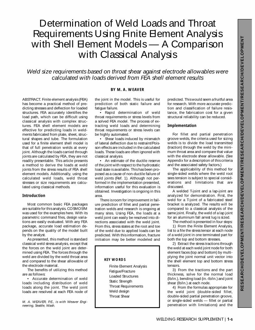
WELDING RESEARCH SUPPLEMENT | 1-s
RE
SE
AR
CH
/DE
VE
LO
PM
EN
T/R
ES
EA
RC
H/D
EV
EL
OP
ME
NT
/RE
SE
AR
CH
/DE
VE
LO
PM
EN
T/R
ES
EA
RC
H/D
EV
EL
OP
ME
NT
BY M. A. WEAVER
Weld size requirements based on throat shear against electrode allowables werecalculated with loads derived from FEA shell element results
Determination of Weld Loads and ThroatRequirements Using Finite Element Analysiswith Shell Element Models — A Comparison
with Classical Analysis
ABSTRACT. Finite element analysis (FEA)has become a practical method of pre-dicting stresses and deflection for loadedstructures. FEA accurately identifies theload path, which can be difficult usingclassical analysis with complex struc-tures. FEA shell element models areeffective for predicting loads in weld-ments fabricated from plate, sheet, struc-tural shapes and tube. The formulationused for a finite element shell model isthat of full penetration welds at everyjoint. Although the loads carried throughjoints are calculated by FEA, they are notreadily presentable. This article presentsa method to derive the loads at weldjoints from the stress results of FEA shellelement models. Additionally, using thecalculated weld loads, weld throatstresses or size requirements are calcu-lated using classical methods.
Introduction
Most common basic FEA packagesare suitable for this analysis. COSMOS/Mwas used for the examples here. With itsparametric command files, design varia-tions are easily evaluated. With any FEApackage, accurate load estimation de-pends on the quality of the model builtby the analyst.
As presented, this method is standardclassical weld stress analysis, except thatthe forces on the weld joint are deter-mined using FEA. The forces through theweld are divided by the weld throat areaand compared to the shear allowable ofthe electrode material.
The benefits of utilizing this methodare as follows:
• Accurate determination of weldloads including distribution of weldloads along the joint. The weld jointloads are resolved at each FEA node of
the joint in the model. This is useful forprediction of both static failure andfatigue failure.
• Rapid determination of weldthroat requirements or stress levels froma solved FEA model. The process of ex-tracting weld loads and determiningthroat requirements or stress levels canbe highly automated.
• Shear loads induced by mismatchof lateral deflection due to restraint/Pois-son effects are included in the calculatedloads. These loads are often ignored withclassical analysis.
• An estimate of the ductile reserveof the joint with respect to the hydrostaticload state is available. This has been pro-posed as a cause of non-ductile failure ofweld joints (Ref. 1). Although not per-formed in the implementation presented,information useful for this evaluation isobtained. Investigation is ongoing in thisarea.
There is room for improvement in fail-ure prediction of fillet and partial pene-tration welds and research is ongoing atmany sites. Using FEA, the loads at aweld joint can easily be resolved into di-rections associated with the weld joint.From this, stress states at the root and toeof the weld due to applied loads can bepredicted. With this information, fractureinitiation may be better modeled and
predicted. This would seem a fruitful areafor research. With more accurate predic-tion and classification of failure resis-tance, the fabrication cost for a givenstructural reliability can be reduced.
Implementation
For fillet and partial penetrationgroove welds, the criteria used for sizingwelds is to divide the load transmitted(traction) through the weld by the mini-mum throat area and compare that valuewith the electrode shear allowable. (SeeAppendix for a description of this criteriaand the associated safety factors.)
The applicability of this method forsingle-sided welds where the weld rootsees tension is subject to special consid-erations and limitations that arediscussed.
A welded T-joint and a lap-joint areanalyzed for demonstration. First, theweld for a T-joint of a fabricated steelbracket is analyzed. The results will becompared to a classical analysis of thesame joint. Finally, the weld of a lap jointfor an aluminum fall arrest lug is sized.
The method is presented in four steps:1) From the Finite Element Analysis,
list to a file the stress tensor at each nodeof a weld joint in one terminated part forboth the top and bottom stresses.
2) Extract the stress tractions throughthe weld at each weld joint node for bothelement faces (top and bottom) by multi-plying the joint normal unit vector intothe shell element top and bottom stresstensors.
3) From the tractions and the partthickness, solve for the normal load(lb/in.), bending load (in.-lb/in.) and jointshear (lb/in.) at each node.
4) From the formulas appropriate forthe weld joint (double-sided fillet,double-sided partial penetration groove,or single-sided welds — fillet or partialpenetration with limitations) and the
KEY WORDS
Finite Element AnalysisFatigue/FractureLoaded StructuresStatic StrengthThroat RequirementsWeld designThroat Shear
M. A. WEAVER, P.E., is with Weaver Engi-neering, Seattle, Wash.
throat size, calculate the weld stress.Conversely, from the desired stress level,solve for the required throat size.
Weld Size Requirement for a SteelT-Joint Bracket
Figure 1 depicts a welded steelbracket loaded vertically and horizon-tally. Figure 2 shows a fabrication detailof the bracket where the size of thedouble-sided fillet weld is S. This T-jointis subject to bending in both the strongand weak directions, tension and shear.
This bracket is made from ASTM A36steel and welded with matching E60XXelectrode. The required safety factoragainst ultimate failure is 3.0, so theallowable weld throat “shear” stress usedto size the joint was 13.2 ksi [1/3.0 ·(60 ksi)(0.3)(2.2)], see Appendix. The ob-jective of this analysis is to determine theweld size, S, that results in a maximumthroat stress of 13.2 ksi.
The loads in the weld are easily de-termined using classical analysis for thisbracket. The weld size requirements willbe calculated first, using the loads fromfinite element analysis and then will becompared to the results obtained usingclassical analysis.
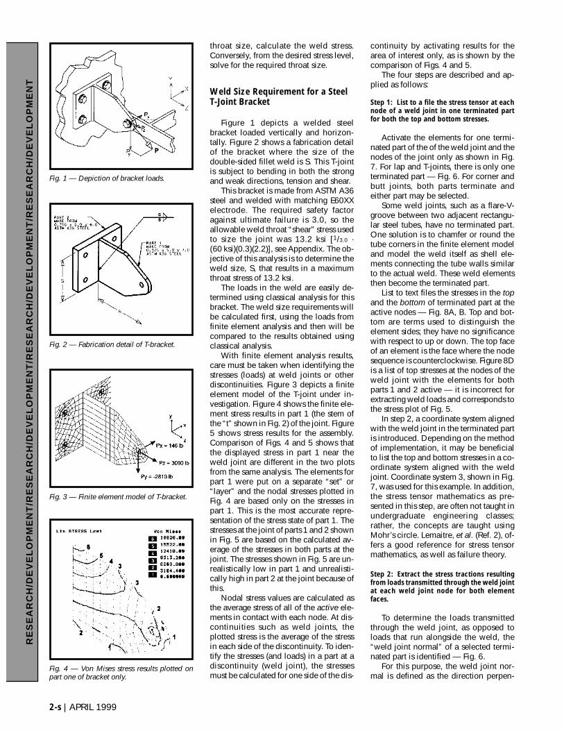
With finite element analysis results,care must be taken when identifying thestresses (loads) at weld joints or otherdiscontinuities. Figure 3 depicts a finiteelement model of the T-joint under in-vestigation. Figure 4 shows the finite ele-ment stress results in part 1 (the stem ofthe “t” shown in Fig. 2) of the joint. Figure5 shows stress results for the assembly.Comparison of Figs. 4 and 5 shows thatthe displayed stress in part 1 near theweld joint are different in the two plotsfrom the same analysis. The elements forpart 1 were put on a separate “set” or“layer” and the nodal stresses plotted inFig. 4 are based only on the stresses inpart 1. This is the most accurate repre-sentation of the stress state of part 1. Thestresses at the joint of parts 1 and 2 shownin Fig. 5 are based on the calculated av-erage of the stresses in both parts at thejoint. The stresses shown in Fig. 5 are un-realistically low in part 1 and unrealisti-cally high in part 2 at the joint because ofthis.
Nodal stress values are calculated asthe average stress of all of the active ele-ments in contact with each node. At dis-continuities such as weld joints, theplotted stress is the average of the stressin each side of the discontinuity. To iden-tify the stresses (and loads) in a part at adiscontinuity (weld joint), the stressesmust be calculated for one side of the dis-
continuity by activating results for thearea of interest only, as is shown by thecomparison of Figs. 4 and 5.
The four steps are described and ap-plied as follows:
Step 1: List to a file the stress tensor at eachnode of a weld joint in one terminated partfor both the top and bottom stresses.
Activate the elements for one termi-nated part of the of the weld joint and thenodes of the joint only as shown in Fig.7. For lap and T-joints, there is only oneterminated part — Fig. 6. For corner andbutt joints, both parts terminate andeither part may be selected.
Some weld joints, such as a flare-V-groove between two adjacent rectangu-lar steel tubes, have no terminated part.One solution is to chamfer or round thetube corners in the finite element modeland model the weld itself as shell ele-ments connecting the tube walls similarto the actual weld. These weld elementsthen become the terminated part.
List to text files the stresses in the topand the bottom of terminated part at theactive nodes — Fig. 8A, B. Top and bot-tom are terms used to distinguish theelement sides; they have no significancewith respect to up or down. The top faceof an element is the face where the nodesequence is counterclockwise. Figure 8Dis a list of top stresses at the nodes of theweld joint with the elements for bothparts 1 and 2 active — it is incorrect forextracting weld loads and corresponds tothe stress plot of Fig. 5.
In step 2, a coordinate system alignedwith the weld joint in the terminated partis introduced. Depending on the methodof implementation, it may be beneficialto list the top and bottom stresses in a co-ordinate system aligned with the weldjoint. Coordinate system 3, shown in Fig.7, was used for this example. In addition,the stress tensor mathematics as pre-sented in this step, are often not taught inundergraduate engineering classes;rather, the concepts are taught usingMohr’s circle. Lemaitre, et al. (Ref. 2), of-fers a good reference for stress tensormathematics, as well as failure theory.
Step 2: Extract the stress tractions resultingfrom loads transmitted through the weld jointat each weld joint node for both elementfaces.
To determine the loads transmittedthrough the weld joint, as opposed toloads that run alongside the weld, the“weld joint normal” of a selected termi-nated part is identified — Fig. 6.
For this purpose, the weld joint nor-mal is defined as the direction perpen-
RE
SE
AR
CH
/DE
VE
LO
PM
EN
T/R
ES
EA
RC
H/D
EV
EL
OP
ME
NT
/RE
SE
AR
CH
/DE
VE
LO
PM
EN
T/R
ES
EA
RC
H/D
EV
EL
OP
ME
NT
2-s | APRIL 1999
Fig. 2 — Fabrication detail of T-bracket.
Fig. 1 — Depiction of bracket loads.
Fig. 3 — Finite element model of T-bracket.
Fig. 4 — Von Mises stress results plotted onpart one of bracket only.
dicular to the plane formed by the axis ofthe weld and the normal (perpendicular)direction of the surface of the terminatedpart at the node of evaluation — Fig. 6.In mathematical terms,
us ≡ surface normal unit vectoruw ≡ weld axis unit vectoruj ≡ weld joint normal unit vectoruj = us × uw.
The stress traction vector, T, acting onthe plane defined by the weld jointnormal vector, uj, results from loadstransmitted through the weld joint. It isextracted by multiplying the weld jointnormal, uj, into the stress tensor, σ.
T = [σ]uj
In expanded notation, the expressionis
One way to resolve the traction into
weld joint coordinate system, (s, w, j) is
where Ts represents the shear acting per-pendicular to the terminated part, Tw rep-resents the weld joint longitudinal shear,and Tj represents the tension or com-pression in the terminated part throughthe weld joint.
For a lap joint, Tj also represents thetransverse shear. If the joint is loaded inplane, (Ts = 0) and there is a transversecomponent to the load (Tj ≠ 0),AWS D1.1, Structural Welding Code —Steel (Ref. 3) has alternate increasedweld load allowables based on trans-verse/longitudinal load orientation. Thistransverse/longitudinal orientation isavailable with these results. Cautionshould be exercised, however, becausealthough joints with transverse in-planeloading have greater strength, they haveless ductility and energy absorptionthan longitudinally-loaded joints. Refer
T
T
T
s
w
j
=
•
•
•
T u
T u
T u
s
w
j
T
T
T
u
u
u
x
y
z
xx xy xz
yx yy yz
zx zy zz
j
j
j
x
y
z
=
σ σ σ
σ σ σ
σ σ σ
WELDING RESEARCH SUPPLEMENT | 3-s
RE
SE
AR
CH
/DE
VE
LO
PM
EN
T/R
ES
EA
RC
H/D
EV
EL
OP
ME
NT
/RE
SE
AR
CH
/DE
VE
LO
PM
EN
T/R
ES
EA
RC
H/D
EV
EL
OP
ME
NT
Fig. 5 — Von Mises stress results plotted for theentire bracket.
Fig. 6 — Weld joint coordinate system of theterminated part.
Fig. 7 — Element and node activation for list-ing part stresses at weld joint.
Fig. 8 — Tabulated FEA and weld calculation results.
to AWS D1.1 Fig. C26 Commentary(Ref. 3).
For the T-bracket, the stresses arelisted in coordinate system 3, which hasthe z-axis aligned with the weld jointnormal. The preceding analysis simpli-fies as
uj = uz
For node 340 of the T-joint (refer toFig. 8), the top and bottom stress tractionsthrough the weld joint are
The extraction of stress tractions re-sulting from loads transmitted throughthe weld joint is complete.
Step 3: From the tractions and the part thick-ness, solve for the normal load (lb/in.), bend-ing load (in.-lb/in.), and joint shear (lb/in.).
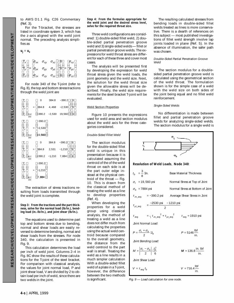
The equations used to determine parttop and bottom stress due to bending,normal and shear loads are easily re-versed to determine bending, normal andshear loads from the stresses. For node340, the calculation is presented inFig. 9.
This calculation determines the loadper inch of weld joint. Columns 2–4 inFig. 8C show the results of these calcula-tions for the T-joint of the steel bracket.For comparison with classical analysis,the values for joint normal load, P andjoint shear load, V are divided by 2 to ob-tain load per inch of weld, since there aretwo welds in the joint.
Step 4: From the formulas appropriate forthe weld joint and the desired stress level,solve for the required throat size.
Three weld configurations are consid-ered: 1) double-sided fillet weld, 2) dou-ble-sided partial penetration grooveweld and 3) single-sided welds — fillet orpartial penetration groove welds. The ex-pressions for weld throat stress are differ-ent for each of these three and cover mostcases.
The analysis will be presented firstby developing the expression for weldthroat stress given the weld loads, thejoint geometry and the weld size. Next,the solution for the weld throat sizegiven the allowable stress will be de-scribed. Finally, the weld size require-ments for the steel bracket T-joint will beevaluated.
Weld Section Properties
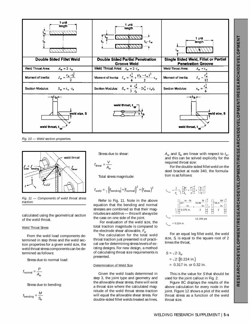
Figure 10 presents the expressionsused for weld area and section modulusabout the weld axis for the three cate-gories considered.
Double-Sided Fillet Weld
The section modulusfor the double-sided filletweld is unique in thispresentation because it iscalculated assuming thecentroid of the of the weldthroat on each side is atthe part outer edge in-stead at the physical cen-troid of the throat — Fig.10. This is drawn fromthe classical method oftreating the weld as a lineto develop properties(Ref. 4).
When developing theproperties for a weldgroup using classicalanalysis, the method oftreating a weld as a linedoes not differ much fromcalculating the propertiesusing the actual weld cen-troid because comparedto the overall geometry,the distance from theweld centroid to the partwall is small. Treating theweld as a line results in amuch simpler calculationWith a double-sided filletweld of a plate in a T-joint,however, the differencebetween the two methodsis significant.
The resulting calculated stresses frombending loads in double-sided filletwelds treated as lines is more conserva-tive. There is a dearth of references onthis subject — most published investiga-tions of fillet weld strength involve lapjoints loaded in plane (Ref. 5). In theabsence of illumination, the safer pathwas chosen.
Double-Sided Partial Penetration GrooveWeld
The section modulus for a double-sided partial penetration groove weld iscalculated using the geometrical sectionof the weld throat. The formulationshown is for the simple case of a weldwith the weld size on both sides ofthe joint being equal and no fillet weldreinforcement.
Single-Sided Welds
No differentiation is made betweenfillet and partial penetration groovewelds for analyzing single-sided welds.The section modulus for a single weld is
T
T
T
T
T
T
x
y
z
x
y
z
=
−
−
− −
=
−
−
BOT
BOT
340
340
0 384 8 390 2
384 8 2 531 1 210
390 2 1 210 7 884
0
0
1
390 2
1 210
7
. .
. , ,
. , ,
.
,
,
884884
T
T
T
T
T
T
x
y
z
x
y
z
=
−
−
− −
=
−
−
TOP
TOP
340
340
0 384 8 390 2
384 8 4 468 2 530
390 2 2 530 19 560
0
0
1
390 2
2 530
19
. .
. , ,
. , ,
.
,
,
560560
T
T
T
x
y
z
xx xy xz
yx yy yz
zx zy zz
xz
yz
zz
=
=
σ σ σ
σ σ σ
σ σ σ
σ
σ
σ
0
0
1
RE
SE
AR
CH
/DE
VE
LO
PM
EN
T/R
ES
EA
RC
H/D
EV
EL
OP
ME
NT
/RE
SE
AR
CH
/DE
VE
LO
PM
EN
T/R
ES
EA
RC
H/D
EV
EL
OP
ME
NT
4-s | APRIL 1999
Fig. 9 — Load calculation for one node.
Resolution of Weld Loads Node 340
in. Base Material Thickness
,560 psi Normal Stress at Top of Joint
psi Normal Stress at Bottom of Joint
psi Average Shear Stress in Joint
psi psi
2
psi
lbf
in.
x_avg
_avg
avg x_avg _avg avg
, :
.
t
Joint Normal Load:
P t P
Joint Bending Load:
Mt
b
t
b
z
yz
z yz
t bb
t b b
= ⋅
=
=
= −
=− −
= + =
=+
⋅ =
=−
⋅
3
8
19
7884
390 2
2530 1210
1910
25146
2 6
2 2
2
σ
σ
τ
τ
τ τ τ τ
σ σ
σ σMM
Joint Shear Load:
V t Vb
=
= =
136 8
716 4
.
.
in. lbf
in.
lbf
in.avgτ
WELDING RESEARCH SUPPLEMENT | 5-s
RE
SE
AR
CH
/DE
VE
LO
PM
EN
T/R
ES
EA
RC
H/D
EV
EL
OP
ME
NT
/RE
SE
AR
CH
/DE
VE
LO
PM
EN
T/R
ES
EA
RC
H/D
EV
EL
OP
ME
NT
calculated using the geometrical sectionof the weld throat.
Weld Throat Stress
From the weld load components de-termined in step three and the weld sec-tion properties for a given weld size, theweld throat stress components can be de-termined as follows:
Stress due to normal load:
Stress due to bending:
Stress due to shear:
Total stress magnitude:
Refer to Fig. 11. Note in the aboveequation that the bending and normalstresses are combined so that their mag-nitudes are additive — this will always bethe case on one side of the joint.
For evaluation of the weld size, thetotal traction magnitude is compared tothe electrode shear allowable, Fa.
The calculation for the total weldthroat traction just presented is of practi-cal use for determining stress levels of ex-isting designs. For new design, a methodof calculating throat size requirements ispresented.
Determination of Weld Size
Given the weld loads determined instep 3, the joint type and geometry andthe allowable shear stress, there will exista throat size where the calculated mag-nitude of the weld throat stress tractionwill equal the allowable shear stress. Fordouble-sided fillet welds treated as lines,
Aw and Sw are linear with respect to tw,and this can be solved explicitly for therequired throat size:
For the double-sided fillet weld on thesteel bracket at node 340, the formula-tion is as follows:
For an equal leg fillet weld, the weldsize, S, is equal to the square root of 2times the throat,
This is the value for S that should beused for the joint callout in Fig. 2.
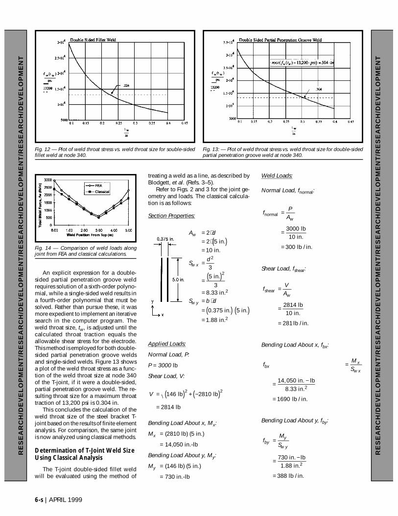
Figure 8C displays the results of theabove calculation for every node in thejoint. Figure 12 shows a plot of the weldthroat stress as a function of the weldthroat size.
S tw= ⋅
= ⋅( )=
2
2 0 224. in. 0.317 in. or 0.32 in.
tF
M
t
P V
t
t
w
a b
w
w
MIN
MIN
MIN
in. - lb
in.
in.
lb
in.
lbf
in.
2
psi
in.
= ⋅ + +
=
+ +
=
1
2 2
137
0 375
5146
2
716 4
13 200
0 224
2 2
2 2
.
.
,
.
f f f fweld bending normal shear= +( ) + ( )2 2
fVAw
shear =
fMSw
bending =
fP
Awnormal =
Fig. 10 — Weld section properties.
Fig. 11 — Components of weld throat stresstraction.
6-s | APRIL 1999
RE
SE
AR
CH
/DE
VE
LO
PM
EN
T/R
ES
EA
RC
H/D
EV
EL
OP
ME
NT
/RE
SE
AR
CH
/DE
VE
LO
PM
EN
T/R
ES
EA
RC
H/D
EV
EL
OP
ME
NT
An explicit expression for a double-sided partial penetration groove weldrequires solution of a sixth-order polyno-mial, while a single-sided weld results ina fourth-order polynomial that must besolved. Rather than pursue these, it wasmore expedient to implement an iterativesearch in the computer program. Theweld throat size, tw, is adjusted until thecalculated throat traction equals theallowable shear stress for the electrode.This method is employed for both double-sided partial penetration groove weldsand single-sided welds. Figure 13 showsa plot of the weld throat stress as a func-tion of the weld throat size at node 340of the T-joint, if it were a double-sided,partial penetration groove weld. The re-sulting throat size for a maximum throattraction of 13,200 psi is 0.304 in.
This concludes the calculation of theweld throat size of the steel bracket T-joint based on the results of finite elementanalysis. For comparison, the same jointis now analyzed using classical methods.
Determination of T-Joint Weld SizeUsing Classical Analysis
The T-joint double-sided fillet weldwill be evaluated using the method of
treating a weld as a line, as described byBlodgett, et al. (Refs. 3–5).
Refer to Figs. 2 and 3 for the joint ge-ometry and loads. The classical calcula-tion is as follows:
Section Properties:
Applied Loads:
Normal Load, P:
P = 3000 lb
Shear Load, V:
Bending Load About x, Mx:
Mx = (2810 lb) (5 in.)
= 14,050 in.-lb
Bending Load About y, My:
My = (146 lb) (5 in.)
= 730 in.-lb
Weld Loads:
Normal Load, fnormal:
Shear Load, fshear:
Bending Load About x, fbx:
Bending Load About y, fby:
fM
Sbyy
w y=
= −
=
230 in. lb1.88 in.
lb / in.
7
388
fMSbx
x
w x=
= −
=
24,050 in. lb
8.33 in.
lb / in.
1
1690
fVAw
shear
814 lb10 in.
lb / in.
=
=
=
2
281
fP
Awnormal
lb10 in.
lb / in.
=
=
=
3000
300
V = ( ) + −( )=
146 2810
2814
2 2 lb lb
lb
RE
SE
AR
CH
/DE
VE
LO
PM
EN
T/R
ES
EA
RC
H/D
EV
EL
OP
ME
NT
/RE
SE
AR
CH
/DE
VE
LO
PM
EN
T/R
ES
EA
RC
H/D
EV
EL
OP
ME
NT
A d
Sd
S b d
w
w x
w y
= ⋅= ⋅( )=
=
= ( )
== ⋅
= ( ) ( )=
2
2 5
3
5
38 33
0 375 5
1 88
2
2
in.10 in.
in.
in.
in. in.
in.
2
2
.
.
.
Fig. 12 — Plot of weld throat stress vs. weld throat size for souble-sidedfillet weld at node 340.
Fig. 13: — Plot of weld throat stress vs. weld throat size for double-sidedpartial penetration groove weld at node 340.
Fig. 14 — Comparison of weld loads alongjoint from FEA and classical calculations.
Total Weld Load, fw:
Required Weld Throat Size, tw:
The required weld throat size as cal-culated using classical analysis is 20%smaller that the value calculated usingthe loads from the FEA. Figure 14 com-pares the weld loads calculated usingFEA and classical analysis. The results arereasonably close. Some causes of the dif-ference are:
1) Poisson Effect — Part 2 of Fig. 2(0.75-in. thick) restrains part 1 (0.375-in.thick) from the lateral contraction/expan-sion associated with the Poisson Ratio,due to normal loads at the weld joint.This induces a shear load that is carriedthrough the weld. The loads obtainedfrom FEA account for this for fnormal,while it is not accounted for in the beamformulas used with classical analysis.(With the current implementation, thePoisson effect due to bending about theweld-weak axis is ignored, because theshear stresses are opposite and theycancel each other in the shear loadcalculation.)
2) Uneven distribution of the loadpath due to the bolts and the non-lineareffects of out-of-plane forces on part 2.
3) End effects.The FEA accounts for these effects,
while the classical analysis used doesnot. The difference between these meth-ods for this joint design is not great andthis steel T-bracket is a good candidatefor classical evaluation.
The finite element analysis method ofdetermining weld loads becomes usefulwhen estimating weld loads using classi-cal analysis is difficult.
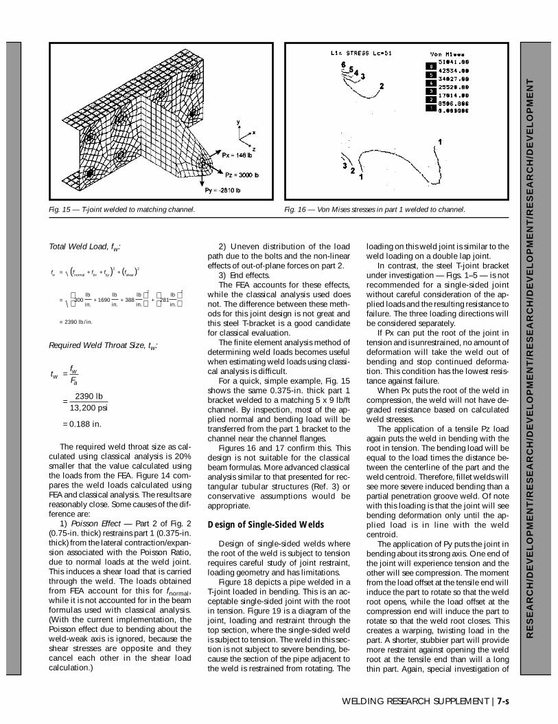
For a quick, simple example, Fig. 15shows the same 0.375-in. thick part 1bracket welded to a matching 5 x 9 lb/ftchannel. By inspection, most of the ap-plied normal and bending load will betransferred from the part 1 bracket to thechannel near the channel flanges.
Figures 16 and 17 confirm this. Thisdesign is not suitable for the classicalbeam formulas. More advanced classicalanalysis similar to that presented for rec-tangular tubular structures (Ref. 3) orconservative assumptions would beappropriate.
Design of Single-Sided Welds
Design of single-sided welds wherethe root of the weld is subject to tensionrequires careful study of joint restraint,loading geometry and has limitations.
Figure 18 depicts a pipe welded in aT-joint loaded in bending. This is an ac-ceptable single-sided joint with the rootin tension. Figure 19 is a diagram of thejoint, loading and restraint through thetop section, where the single-sided weldis subject to tension. The weld in this sec-tion is not subject to severe bending, be-cause the section of the pipe adjacent tothe weld is restrained from rotating. The
loading on this weld joint is similar to theweld loading on a double lap joint.
In contrast, the steel T-joint bracketunder investigation — Figs. 1–5 — is notrecommended for a single-sided jointwithout careful consideration of the ap-plied loads and the resulting resistance tofailure. The three loading directions willbe considered separately.
If Px can put the root of the joint intension and is unrestrained, no amount ofdeformation will take the weld out ofbending and stop continued deforma-tion. This condition has the lowest resis-tance against failure.
When Px puts the root of the weld incompression, the weld will not have de-graded resistance based on calculatedweld stresses.
The application of a tensile Pz loadagain puts the weld in bending with theroot in tension. The bending load will beequal to the load times the distance be-tween the centerline of the part and theweld centroid. Therefore, fillet welds willsee more severe induced bending than apartial penetration groove weld. Of notewith this loading is that the joint will seebending deformation only until the ap-plied load is in line with the weldcentroid.
The application of Py puts the joint inbending about its strong axis. One end ofthe joint will experience tension and theother will see compression. The momentfrom the load offset at the tensile end willinduce the part to rotate so that the weldroot opens, while the load offset at thecompression end will induce the part torotate so that the weld root closes. Thiscreates a warping, twisting load in thepart. A shorter, stubbier part will providemore restraint against opening the weldroot at the tensile end than will a longthin part. Again, special investigation of
tfFww
a=
=
=
2390
0 188
lb13,200 psi
in..
f f f f fw bx by
= + + +
= + + +
=
( ) ( )
normal shear
lb
in.
lb
in.
lb
in.
lb
in.
lb / in.
2 2
2 2
300 1690 388 281
2390
WELDING RESEARCH SUPPLEMENT | 7-s
RE
SE
AR
CH
/DE
VE
LO
PM
EN
T/R
ES
EA
RC
H/D
EV
EL
OP
ME
NT
/RE
SE
AR
CH
/DE
VE
LO
PM
EN
T/R
ES
EA
RC
H/D
EV
EL
OP
ME
NT
Fig. 15 — T-joint welded to matching channel. Fig. 16 — Von Mises stresses in part 1 welded to channel.
the joint against the desired resistance tofailure is required.
Configurations with one-sided filletwelds where the root is in unconstrainedtension are good candidates for redesign.
The single-sided formulation is usedfor double fillet welded lap joints asshown in Fig. 20. Even though this is adouble weld joint, each weld is evalu-ated individually
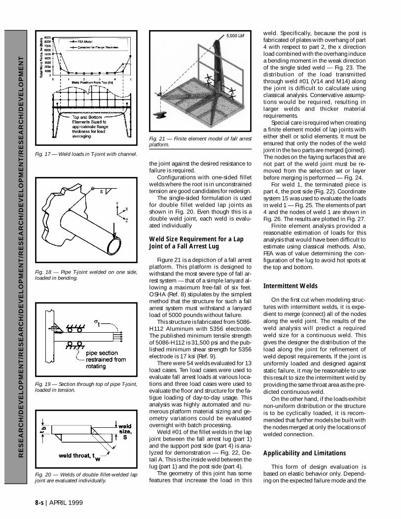
Weld Size Requirement for a LapJoint of a Fall Arrest Lug
Figure 21 is a depiction of a fall arrestplatform. This platform is designed towithstand the most severe type of fall ar-rest system — that of a simple lanyard al-lowing a maximum free-fall of six feet.OSHA (Ref. 8) stipulates by the simplestmethod that the structure for such a fallarrest system must withstand a lanyardload of 5000 pounds without failure.
This structure is fabricated from 5086-H112 Aluminum with 5356 electrode.The published minimum tensile strengthof 5086-H112 is 31,500 psi and the pub-lished minimum shear strength for 5356electrode is 17 ksi (Ref. 9).
There were 54 welds evaluated for 13load cases. Ten load cases were used toevaluate fall arrest loads at various loca-tions and three load cases were used toevaluate the floor and structure for the fa-tigue loading of day-to-day usage. Thisanalysis was highly automated and nu-merous platform material sizing and ge-ometry variations could be evaluatedovernight with batch processing.
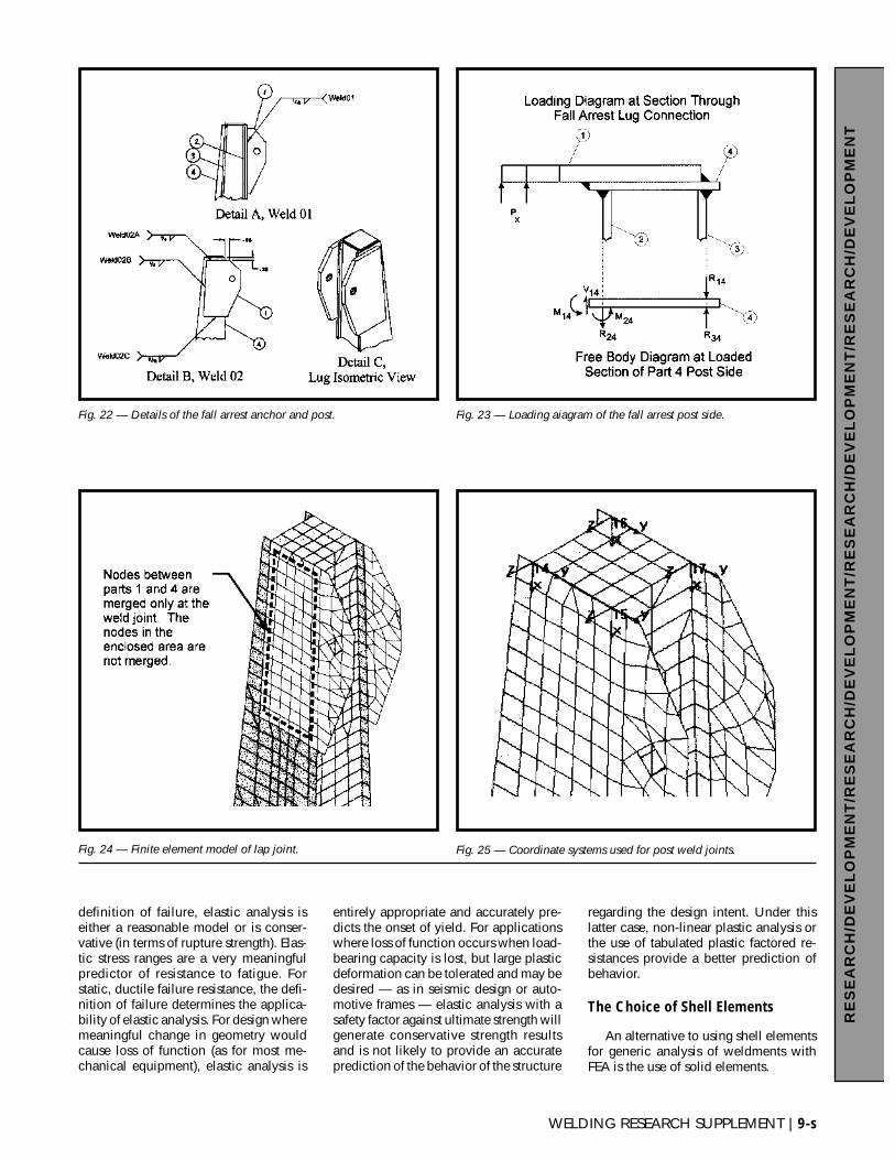
Weld #01 of the fillet welds in the lapjoint between the fall arrest lug (part 1)and the support post side (part 4) is ana-lyzed for demonstration — Fig. 22, De-tail A. This is the inside weld between thelug (part 1) and the post side (part 4).
The geometry of this joint has somefeatures that increase the load in this
weld. Specifically, because the post isfabricated of plates with overhang of part4 with respect to part 2, the x directionload combined with the overhang inducea bending moment in the weak directionof the single sided weld — Fig. 23. Thedistribution of the load transmittedthrough weld #01 (V14 and M14) alongthe joint is difficult to calculate usingclassical analysis. Conservative assump-tions would be required, resulting inlarger welds and thicker materialrequirements.
Special care is required when creatinga finite element model of lap joints witheither shell or solid elements. It must beensured that only the nodes of the weldjoint in the two parts are merged (joined).The nodes on the faying surfaces that arenot part of the weld joint must be re-moved from the selection set or layerbefore merging is performed — Fig. 24.
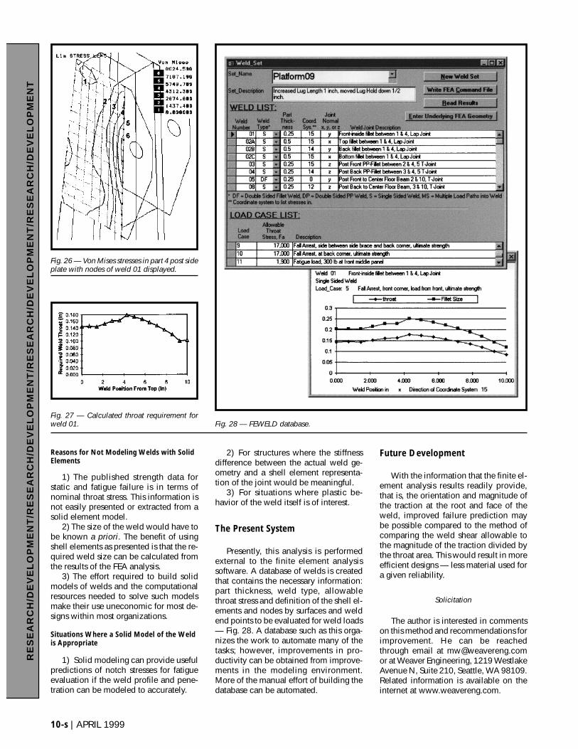
For weld 1, the terminated piece ispart 4, the post side (Fig. 22). Coordinatesystem 15 was used to evaluate the loadsin weld 1 — Fig. 25. The elements of part4 and the nodes of weld 1 are shown inFig. 26. The results are plotted in Fig. 27.
Finite element analysis provided areasonable estimation of loads for thisanalysis that would have been difficult toestimate using classical methods. Also,FEA was of value determining the con-figuration of the lug to avoid hot spots atthe top and bottom.
Intermittent Welds
On the first cut when modeling struc-tures with intermittent welds, it is expe-dient to merge (connect) all of the nodesalong the weld joint. The results of theweld analysis will predict a requiredweld size for a continuous weld. Thisgives the designer the distribution of theload along the joint for refinement ofweld deposit requirements. If the joint isuniformly loaded and designed againststatic failure, it may be reasonable to usethis result to size the intermittent weld byproviding the same throat area as the pre-dicted continuous weld.
On the other hand, if the loads exhibitnon-uniform distribution or the structureis to be cyclically loaded, it is recom-mended that further models be built withthe nodes merged at only the locations ofwelded connection.
Applicability and Limitations
This form of design evaluation isbased on elastic behavior only. Depend-ing on the expected failure mode and the
8-s | APRIL 1999
RE
SE
AR
CH
/DE
VE
LO
PM
EN
T/R
ES
EA
RC
H/D
EV
EL
OP
ME
NT
/RE
SE
AR
CH
/DE
VE
LO
PM
EN
T/R
ES
EA
RC
H/D
EV
EL
OP
ME
NT
Fig. 17 — Weld loads in T-joint with channel.
Fig. 18 — Pipe T-joint welded on one side,loaded in bending.
Fig. 19 — Section through top of pipe T-joint,loaded in tension.
Fig. 20 — Welds of double fillet-welded lapjoint are evaluated individually.
Fig. 21 — Finite element model of fall arrestplatform.
definition of failure, elastic analysis iseither a reasonable model or is conser-vative (in terms of rupture strength). Elas-tic stress ranges are a very meaningfulpredictor of resistance to fatigue. Forstatic, ductile failure resistance, the defi-nition of failure determines the applica-bility of elastic analysis. For design wheremeaningful change in geometry wouldcause loss of function (as for most me-chanical equipment), elastic analysis is
entirely appropriate and accurately pre-dicts the onset of yield. For applicationswhere loss of function occurs when load-bearing capacity is lost, but large plasticdeformation can be tolerated and may bedesired — as in seismic design or auto-motive frames — elastic analysis with asafety factor against ultimate strength willgenerate conservative strength resultsand is not likely to provide an accurateprediction of the behavior of the structure
regarding the design intent. Under thislatter case, non-linear plastic analysis orthe use of tabulated plastic factored re-sistances provide a better prediction ofbehavior.
The Choice of Shell Elements
An alternative to using shell elementsfor generic analysis of weldments withFEA is the use of solid elements.
WELDING RESEARCH SUPPLEMENT | 9-s
RE
SE
AR
CH
/DE
VE
LO
PM
EN
T/R
ES
EA
RC
H/D
EV
EL
OP
ME
NT
/RE
SE
AR
CH
/DE
VE
LO
PM
EN
T/R
ES
EA
RC
H/D
EV
EL
OP
ME
NT
Fig. 22 — Details of the fall arrest anchor and post. Fig. 23 — Loading aiagram of the fall arrest post side.
Fig. 24 — Finite element model of lap joint. Fig. 25 — Coordinate systems used for post weld joints.
Reasons for Not Modeling Welds with SolidElements
1) The published strength data forstatic and fatigue failure is in terms ofnominal throat stress. This information isnot easily presented or extracted from asolid element model.
2) The size of the weld would have tobe known a priori. The benefit of usingshell elements as presented is that the re-quired weld size can be calculated fromthe results of the FEA analysis.
3) The effort required to build solidmodels of welds and the computationalresources needed to solve such modelsmake their use uneconomic for most de-signs within most organizations.
Situations Where a Solid Model of the Weldis Appropriate
1) Solid modeling can provide usefulpredictions of notch stresses for fatigueevaluation if the weld profile and pene-tration can be modeled to accurately.
2) For structures where the stiffnessdifference between the actual weld ge-ometry and a shell element representa-tion of the joint would be meaningful.
3) For situations where plastic be-havior of the weld itself is of interest.
The Present System
Presently, this analysis is performedexternal to the finite element analysissoftware. A database of welds is createdthat contains the necessary information:part thickness, weld type, allowablethroat stress and definition of the shell el-ements and nodes by surfaces and weldend points to be evaluated for weld loads— Fig. 28. A database such as this orga-nizes the work to automate many of thetasks; however, improvements in pro-ductivity can be obtained from improve-ments in the modeling environment.More of the manual effort of building thedatabase can be automated.
Future Development
With the information that the finite el-ement analysis results readily provide,that is, the orientation and magnitude ofthe traction at the root and face of theweld, improved failure prediction maybe possible compared to the method ofcomparing the weld shear allowable tothe magnitude of the traction divided bythe throat area. This would result in moreefficient designs — less material used fora given reliability.
Solicitation
The author is interested in commentson this method and recommendations forimprovement. He can be reachedthrough email at [email protected] at Weaver Engineering, 1219 WestlakeAvenue N, Suite 210, Seattle, WA 98109.Related information is available on theinternet at www.weavereng.com.
RE
SE
AR
CH
/DE
VE
LO
PM
EN
T/R
ES
EA
RC
H/D
EV
EL
OP
ME
NT
/RE
SE
AR
CH
/DE
VE
LO
PM
EN
T/R
ES
EA
RC
H/D
EV
EL
OP
ME
NT
10-s | APRIL 1999
Fig. 26 — Von Mises stresses in part 4 post sideplate with nodes of weld 01 displayed.
Fig. 27 — Calculated throat requirement forweld 01. Fig. 28 — FEWELD database.
References
1. Blodgett, O. W. 1995. Details to In-crease Ductility in SMRF Connections. TheWelding Innovation Quarterly XII (2). TheJames F. Lincoln Arc Welding Foundation.
2. Lemaitre, J., and Chaboche, J. -L. 1990.Mechanics of Solid Materials. Cambridge Uni-versity Press.
3. ANSI/AWS D1.1-96, Structural Weld-ing Code — Steel, 15th Ed. 1996. AmericanWelding Society, Miami, Fla.
4. Blodgett, O. W. 1963. Design of Weld-ments. The James F. Lincoln Arc WeldingFoundation.
5. Higgins, T. R., and Preece, F. R. 1968.Proposed working stresses for fillet welds inbuilding construction. Welding Journal47(10): 429-s to 432-s.
6. Shigley, J. E., and Mischke, C. R. 1989Mechanical Engineering Design, 5th Ed.McGraw-Hill Book Company.
7. Welding Handbook. 8th Ed., Vol. 1.1987. American Welding Society, Miami, Fla.
8. 29 CFR 1910.66 Appendix C. 1997.Occupational Safety and Health Administra-tion. Office of the Federal Register, NationalArchives and Records Administration. U.S.Government Printing Office.
9. Specifications for Aluminum Structures,5th Ed. 1986. The Aluminum Association.
10. Lesik, D. F., and Kennedy, D. J. L.,1990. Ultimate strength of fillet welded con-nections loaded in plane. Canadian Journal ofCivil Engineering. 17: 55–67.
11. Fisher, J. W., Frank, K. H., Hirt, M. A.,and McNamee, B. M. 1970. Effect of Weld-ments on Fatigue Strength of Steel Beams. Re-port No. 102. National Cooperative HighwayResearch Program, Transportation ResearchBoard, National Academy of Sciences.
12. Fisher, J. W., Albrecht, P. A., Yen, B. T.,Klingerman, D. J., and McNamee, B. M. 1974.Fatigue Strength of Steel Beams with WeldedStiffeners and Attachments. Report No. 147.National Cooperative Highway Research Pro-gram, Transportation Research Board, Na-tional Academy of Sciences.
Appendix
Stress Criteria for Fillet Weldswith AWS D1.1
The following is the method and ratio-nale of applying the requirements of AWSD1.1 (Ref. 3) for weld size determination.
The shear stress allowable for staticloading in the Structural Welding Code,AWS D1.1, is 0.3 times the electrode ten-sile strength for fillet welds and partialpenetration groove welds not in bearing,except fillet welds of lap joints loaded inplane with a transverse load componenthave an increased allowable per 2.14 ofAWS D1.1-96. See also Lesik (Ref. 10).The increased allowable is new with the1996 code. There are no directly pub-lished shear strengths for steel electrodesin AWS D1.1 or AWS electrode specifi-cations; however, the commentary forsection 2 (section 8 for pre-1996 versionsof AWS D1.1) does reveal that the allow-
able stress is based on a safety factorranging from 2.2 for in-plane longitudi-nal shear to 4.6 for in-plane transverseloads based on test results (Ref 5). Thesetests were performed on lap joints loadedin-plane. Based on this datum, the mini-mum ultimate shear strength for steelelectrode used for analysis is taken as0.66 (= 0.3 x 2.2) times the electrodeminimum tensile strength. Because out-of-plane loading was not evaluated in thetesting referenced by the AWS D1.1 andvery few testing results of out-of-planeloading have been published, the lowersafety factor of 2.2 is used to estimatejoint strength by the author for all jointsloaded out of plane. For E60XX elec-trode, this results in an ultimate shearstrength of 39.6 ksi. For tubular structureswelded with 60 or 70 ksi electrode, thestrength is taken as 2.67 times theallowable stress, per 2.40.1.3.
This is useful when designing forcompliance with codes and specificationsrequiring other safety factors for staticloading. For example, ANSI/ALIB153.1-90, American National Standardfor Automotive Lifts — Safety Require-ments requires a safety factor of 3.0against ultimate failure for ductile materialwhile deferring to “ANSI/AWS D1.1-90Sections 1 through 7, Section 8 where ap-plicable, …”, “… and the Commentary onStructural Welding Code — Steel, (Part ofANSI/AWS D1.1)” for welding techniquesand weld joint design. The resulting al-lowable weld throat shear stress used fordesign with this code is 13.2 ksi (= 1/3.0 ·39.6 ks) for E60XX electrode.
Of note is the evaluation of only thestresses due to loads carried through theweld joint. Stresses along the axis of theweld from loads not passing through theweld are not used (see note 3 in Table 2.3of AWS D1.1-96). With respect to staticloading resistance, these axial stresseswill participate in the onset of yield, in-creasing or decreasing the load at whichyield initiates depending on the load ge-ometry. A justification for this approachcan be made for fillet and partial pene-tration welds, where the weld cross sec-tion is less than the base metal crosssection for axial loads and the weld sizesare not great. As far as the weld is con-cerned, these axial stresses are seen asapplied axial strains and a small amountof yielding will relieve the stresses asso-ciated with them, while the base metalremains in an elastic state. This is true,because the weld will be constrained tostrain in the axial direction by the sameamount as the base material adjacent tothe weld. If the weld cross section is sig-nificant compared to the base metal cross-section for axial load, this assumption
will be attenuated and further investiga-tion is suggested. Also, in the case ofplastic design where the base material isexpected to see large deformation, thecombined effects of axial and throughweld elongation must be considered inthe resistance of the joint. A high, tensilehydrostatic stress state (associated withlarge welds combined with severe cross-section or load path discontinuities, suchas mismatched base metal sizes) willcause a crack to propagate across thejoint before its theoretical ductile limit isreached. It is good to remember that fil-let and partial penetration welds arebrought into this world with the equiva-lent of a crack at the root.
The method used to size fillet weldsagainst ductile failure is based on thepractical approach of comparing themagnitude of the stress resulting fromloads passing through the weld joint tothe electrode and base metal shearstrengths. From the standpoint of the me-chanics discipline of physics, this ap-proach is close for a joint in purelongitudinal shear only. In general, forother loading geometries, this approachresults in a more conservative (earlierfailure) prediction than other ductile fail-ure theories. However, factors such asthe high-stress concentration at the weldroot, residual stresses and distortion in-duced by the welding process, and welddefects call for a conservative approach.
Per AWS D1.1-96 for dynamically-loaded structures (fatigue), the allow-ables for stress range in the fillet weld arealso in terms of shear on the weld throat(Category F, Table 2.4 and Figs. 2.9 and2.10). The values for redundant struc-tures correspond to the underlying studyreferenced in the commentary (Refs. 11,12), where the recommendations aredrawn for a 95% survival rate at a 95%confidence level from the underlying testdata. These studies are oriented directlyat bridge construction. The total stressstate in a fillet weld — not just the trac-tion through the throat — will contributeto fatigue failure; however, the tractionthrough the throat is subject to the stressconcentration at the root, while stressesalong the weld axis are not. Because theroot is essentially a crack, the weld isborn into stage 2 fatigue with respect toloads through the weld while the weld iscloser to stage 1 fatigue for loads alongthe weld axis. Additionally, there are sep-arate allowables for stresses in the basemetal adjacent to weld joints that arenear the same range as the allowables forthe weld throat shear (Categories Bthrough E, Table 2.4 of AWS D1.1-96).These account for the load path discon-tinuity at the welds and notch effect.
WELDING RESEARCH SUPPLEMENT | 11-s
RE
SE
AR
CH
/DE
VE
LO
PM
EN
T/R
ES
EA
RC
H/D
EV
EL
OP
ME
NT
/RE
SE
AR
CH
/DE
VE
LO
PM
EN
T/R
ES
EA
RC
H/D
EV
EL
OP
ME
NT


![arXiv:math/0205184v2 [math.AP] 17 Jun 2002 › pdf › math › 0205184.pdfwith almost periodic, rapidly oscillating principal part and nonlinear interactions. Under suitable hypothesis](https://static.fdocument.org/doc/165x107/60c4fa914bc327425821fcd1/arxivmath0205184v2-mathap-17-jun-2002-a-pdf-a-math-a-with-almost-periodic.jpg)