
D E S IG N O F A S U R F A C E M U O N B E A M L IN E F O...
3
DESIGN OF A SURFACE MUON BEAM LINE FOR HIGH FIELD SR AT THE PSI PROTON ACCELERATOR FACILITY K. Deiters, P. Kaufmann, T. Prokscha, T. Rauber, D. Reggiani # , R. Scheuermann, K. Sedlak, V. Vranković, Paul Scherrer Institut, 5232 Villigen PSI, Switzerland Y. Lee, European Spallation Source ESS AB, 221 00 Lund, Sweden Abstract Starting from 2012, a High Field μSR (muon spin rotation/relaxation/resonance) facility will come into operation in the πE3 secondary beam line located at the target station E of the PSI proton accelerator. For this purpose, the last part of the beam line was redesigned in order to integrate two electrostatic spin rotator devices providing a 90° rotation of the muon spin. At the same time, requirements of small beam diameter (σ x,y ≈ 15 mm) as well as small momentum bite (Δp/p ≈ 2 %) in the sample region have to be met. This work focuses on the simulation of the beam optics (27.4 MeV/c design momentum). Particular concern is given to potential transmission losses caused by the spin rotator devices. The matching of the beam line with the high magnetic field up to 9.5 T surrounding the sample region is considered as well. An overview of the spin rotator devices, specifically designed for this project, is also presented. INTRODUCTION The Laboratory for Muon Spin Spectroscopy (LMU) presently operates six facilities devoted to μSR research [1] employing the continuous muon beam made available by the Swiss Muon Source (SμS) at PSI. In μSR experiments polarized muons are used to probe extremely small local magnetic fields, including their spatial distribution and temporal fluctuations, in any form of matter [2]. The new High Field μSR facility will allow to study the dependence of material properties on external magnetic fields up to the unprecedented value of 9.5 T as well as on temperatures ranging from 0.02 to 320 K [3]. The design and construction of the new instrument was completed in 2011. In order to ensure stable operation of the new facility, the πE3 secondary beam line of the PSI proton accelerator, which provides a high intensity longitudinally polarized surface muon beam, has been permanently devoted to this new installation. For this purpose, the second half of the beam line was completely redesigned with the insertion of two new so-called spin rotator devices providing a virtually fully transversely polarized beam at the location of the sample material. Simulations were performed in order to optimize the beam transmission through the spin rotator system as well as the beam spot size at the probe location and to study, at the same time, the dependence of the latter on the magnitude of the large magnetic field provided by the μSR instrument. Fig. 1 shows a 3D visualization of the newly designed beam line section along with the installation of the High Field μSR facility. DESIGN OF THE SPIN ROTATORS Spin rotator (SR) devices generate crossed static magnetic and electric fields in order to rotate the beam particle spin without bending the beam trajectory. At the same time, they act as velocity filters (Wien Filter). At PSI, an extensive know-how in the operation of electrostatic elements, like SRs and separators, has been gained over years of operation of such devices. It was therefore a natural choice to carry out an in-house design of the new elements. The High Field μSR facility requires a 90° rotation of the muon spin, which translates, for 28 MeV/c beam, to a typical rotation path of over 3 m length. Since such a distance would be too large for a single element, two SR devices, each rotating the spin by 45°, were conceived. In order to keep the high voltage (HV) below ±200 kV, the electrodes gap was set to 12 cm and the effective length to 180 cm. The full spin rotation is reached by means of an effective magnetic field of ≈ 38 mT, corresponding to an Figure 1: The section of the πE3 beam line redesigned for the High Field μSR project. The big yellow frames enclose the spin-rotators devices, while the red elements represent quadrupole magnets. On the left side the High Field μSR facility is visible. The muon beam comes from the right. ___________________________________________ #dav[email protected] mu TUPPC035 Proceedings of IPAC2012, New Orleans, Louisiana, USA ISBN 978-3-95450-115-1 1236 Copyright c ○ 2012 by IEEE – cc Creative Commons Attribution 3.0 (CC BY 3.0) — cc Creative Commons Attribution 3.0 (CC BY 3.0) 05 Beam Dynamics and Electromagnetic Fields D01 Beam Optics - Lattices, Correction Schemes, Transport
Transcript of D E S IG N O F A S U R F A C E M U O N B E A M L IN E F O...
DESIGN OF A SURFACE MUON BEAM LINE FOR HIGH FIELD SR AT THE PSI PROTON ACCELERATOR FACILITY
K. Deiters, P. Kaufmann, T. Prokscha, T. Rauber, D. Reggiani#, R. Scheuermann, K. Sedlak, V. Vranković, Paul Scherrer Institut, 5232 Villigen PSI, Switzerland Y. Lee, European Spallation Source ESS AB, 221 00 Lund, Sweden
Abstract
Starting from 2012, a High Field μSR (muon spin rotation/relaxation/resonance) facility will come into operation in the πE3 secondary beam line located at the target station E of the PSI proton accelerator. For this purpose, the last part of the beam line was redesigned in order to integrate two electrostatic spin rotator devices providing a 90° rotation of the muon spin. At the same time, requirements of small beam diameter (σx,y ≈ 15 mm) as well as small momentum bite (Δp/p ≈ 2 %) in the sample region have to be met. This work focuses on the simulation of the beam optics (27.4 MeV/c design momentum). Particular concern is given to potential transmission losses caused by the spin rotator devices. The matching of the beam line with the high magnetic field up to 9.5 T surrounding the sample region is considered as well. An overview of the spin rotator devices, specifically designed for this project, is also presented.
INTRODUCTION The Laboratory for Muon Spin Spectroscopy (LMU)
presently operates six facilities devoted to μSR research [1] employing the continuous muon beam made available by the Swiss Muon Source (SμS) at PSI. In μSR experiments polarized muons are used to probe extremely small local magnetic fields, including their spatial distribution and temporal fluctuations, in any form of matter [2]. The new High Field μSR facility will allow to study the dependence of material properties on external magnetic fields up to the unprecedented value of 9.5 T as well as on temperatures ranging from 0.02 to 320 K [3]. The design and construction of the new instrument was completed in 2011. In order to ensure stable operation of the new facility, the πE3 secondary beam line of the PSI
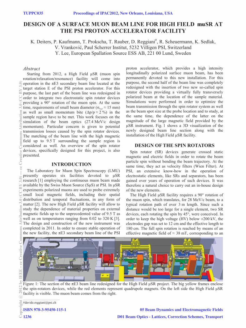
proton accelerator, which provides a high intensity longitudinally polarized surface muon beam, has been permanently devoted to this new installation. For this purpose, the second half of the beam line was completely redesigned with the insertion of two new so-called spin rotator devices providing a virtually fully transversely polarized beam at the location of the sample material. Simulations were performed in order to optimize the beam transmission through the spin rotator system as well as the beam spot size at the probe location and to study, at the same time, the dependence of the latter on the magnitude of the large magnetic field provided by the μSR instrument. Fig. 1 shows a 3D visualization of the newly designed beam line section along with the installation of the High Field μSR facility.
DESIGN OF THE SPIN ROTATORS Spin rotator (SR) devices generate crossed static
magnetic and electric fields in order to rotate the beam particle spin without bending the beam trajectory. At the same time, they act as velocity filters (Wien Filter). At PSI, an extensive know-how in the operation of electrostatic elements, like SRs and separators, has been gained over years of operation of such devices. It was therefore a natural choice to carry out an in-house design of the new elements.
The High Field μSR facility requires a 90° rotation of the muon spin, which translates, for 28 MeV/c beam, to a typical rotation path of over 3 m length. Since such a distance would be too large for a single element, two SR devices, each rotating the spin by 45°, were conceived. In order to keep the high voltage (HV) below ±200 kV, the electrodes gap was set to 12 cm and the effective length to 180 cm. The full spin rotation is reached by means of an effective magnetic field of ≈ 38 mT, corresponding to an
Figure 1: The section of the πE3 beam line redesigned for the High Field μSR project. The big yellow frames enclose the spin-rotators devices, while the red elements represent quadrupole magnets. On the left side the High Field μSR facility is visible. The muon beam comes from the right. ___________________________________________ #[email protected]
mu
TUPPC035 Proceedings of IPAC2012, New Orleans, Louisiana, USA
ISBN 978-3-95450-115-1
1236Cop
yrig
htc ○
2012
byIE
EE
–cc
Cre
ativ
eC
omm
onsA
ttri
butio
n3.
0(C
CB
Y3.
0)—
ccC
reat
ive
Com
mon
sAtt
ribu
tion
3.0
(CC
BY
3.0)
05 Beam Dynamics and Electromagnetic Fields
D01 Beam Optics - Lattices, Correction Schemes, Transport
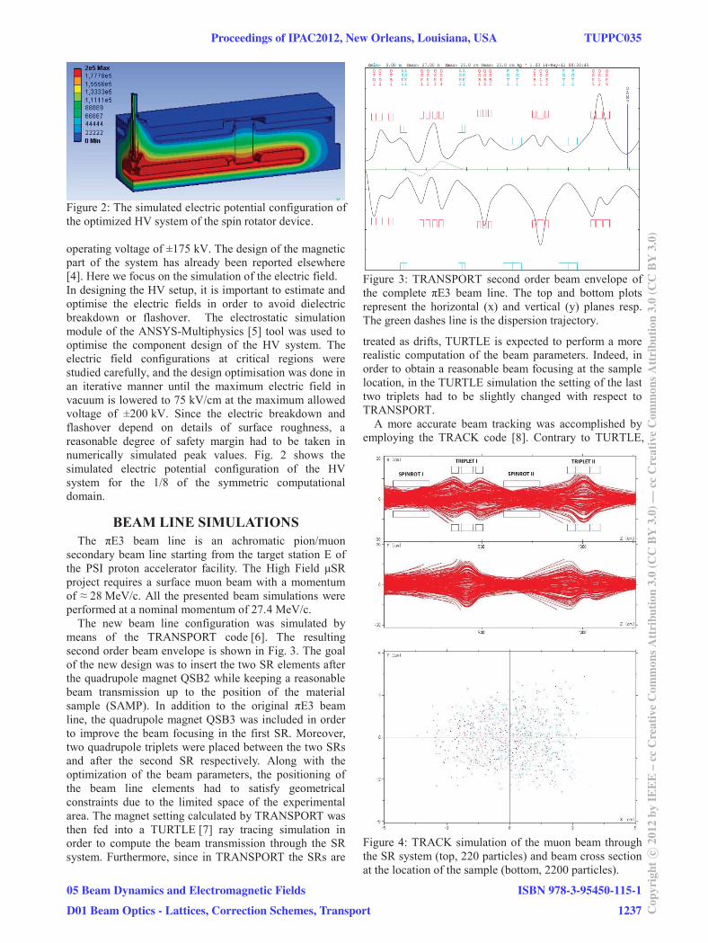
Figure 2: The simulated electric potential configuration of the optimized HV system of the spin rotator device. operating voltage of ±175 kV. The design of the magnetic part of the system has already been reported elsewhere [4]. Here we focus on the simulation of the electric field. In designing the HV setup, it is important to estimate and optimise the electric fields in order to avoid dielectric breakdown or flashover. The electrostatic simulation module of the ANSYS-Multiphysics [5] tool was used to optimise the component design of the HV system. The electric field configurations at critical regions were studied carefully, and the design optimisation was done in an iterative manner until the maximum electric field in vacuum is lowered to 75 kV/cm at the maximum allowed voltage of ±200 kV. Since the electric breakdown and flashover depend on details of surface roughness, a reasonable degree of safety margin had to be taken in numerically simulated peak values. Fig. 2 shows the simulated electric potential configuration of the HV system for the 1/8 of the symmetric computational domain.
BEAM LINE SIMULATIONS The πE3 beam line is an achromatic pion/muon
secondary beam line starting from the target station E of the PSI proton accelerator facility. The High Field μSR project requires a surface muon beam with a momentum of ≈ 28 MeV/c. All the presented beam simulations were performed at a nominal momentum of 27.4 MeV/c.
The new beam line configuration was simulated by means of the TRANSPORT code [6]. The resulting second order beam envelope is shown in Fig. 3. The goal of the new design was to insert the two SR elements after the quadrupole magnet QSB2 while keeping a reasonable beam transmission up to the position of the material sample (SAMP). In addition to the original πE3 beam line, the quadrupole magnet QSB3 was included in order to improve the beam focusing in the first SR. Moreover, two quadrupole triplets were placed between the two SRs and after the second SR respectively. Along with the optimization of the beam parameters, the positioning of the beam line elements had to satisfy geometrical constraints due to the limited space of the experimental area. The magnet setting calculated by TRANSPORT was then fed into a TURTLE [7] ray tracing simulation in order to compute the beam transmission through the SR system. Furthermore, since in TRANSPORT the SRs are
Figure 3: TRANSPORT second order beam envelope of the complete πE3 beam line. The top and bottom plots represent the horizontal (x) and vertical (y) planes resp. The green dashes line is the dispersion trajectory.
treated as drifts, TURTLE is expected to perform a more realistic computation of the beam parameters. Indeed, in order to obtain a reasonable beam focusing at the sample location, in the TURTLE simulation the setting of the last two triplets had to be slightly changed with respect to TRANSPORT.
A more accurate beam tracking was accomplished by employing the TRACK code [8]. Contrary to TURTLE,
Figure 4: TRACK simulation of the muon beam through the SR system (top, 220 particles) and beam cross section at the location of the sample (bottom, 2200 particles).
Proceedings of IPAC2012, New Orleans, Louisiana, USA TUPPC035
05 Beam Dynamics and Electromagnetic Fields
D01 Beam Optics - Lattices, Correction Schemes, Transport
ISBN 978-3-95450-115-1
1237 Cop
yrig
htc ○
2012
byIE
EE
–cc
Cre
ativ
eC
omm
onsA
ttri
butio
n3.
0(C
CB
Y3.
0)—
ccC
reat
ive
Com
mon
sAtt
ribu
tion
3.0
(CC
BY
3.0)
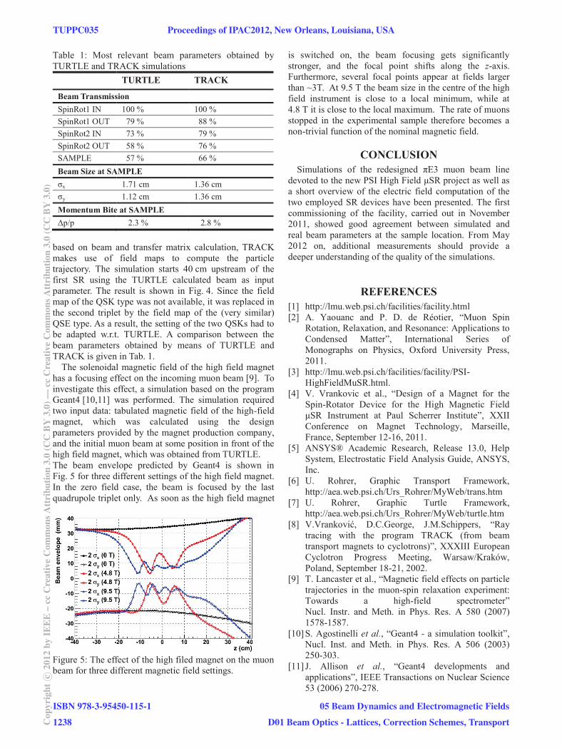
Table 1: Most relevant beam parameters obtained by TURTLE and TRACK simulations
TURTLE TRACK
Beam Transmission SpinRot1 IN 100 % 100 % SpinRot1 OUT 79 % 88 % SpinRot2 IN 73 % 79 % SpinRot2 OUT 58 % 76 % SAMPLE 57 % 66 % Beam Size at SAMPLE σx 1.71 cm 1.36 cm σy 1.12 cm 1.36 cm Momentum Bite at SAMPLE Δp/p 2.3 % 2.8 %
based on beam and transfer matrix calculation, TRACK makes use of field maps to compute the particle trajectory. The simulation starts 40 cm upstream of the first SR using the TURTLE calculated beam as input parameter. The result is shown in Fig. 4. Since the field map of the QSK type was not available, it was replaced in the second triplet by the field map of the (very similar) QSE type. As a result, the setting of the two QSKs had to be adapted w.r.t. TURTLE. A comparison between the beam parameters obtained by means of TURTLE and TRACK is given in Tab. 1.
The solenoidal magnetic field of the high field magnet has a focusing effect on the incoming muon beam [9]. To investigate this effect, a simulation based on the program Geant4 [10,11] was performed. The simulation required two input data: tabulated magnetic field of the high-field magnet, which was calculated using the design parameters provided by the magnet production company, and the initial muon beam at some position in front of the high field magnet, which was obtained from TURTLE. The beam envelope predicted by Geant4 is shown in Fig. 5 for three different settings of the high field magnet. In the zero field case, the beam is focused by the last quadrupole triplet only. As soon as the high field magnet
Figure 5: The effect of the high filed magnet on the muon beam for three different magnetic field settings.
is switched on, the beam focusing gets significantly stronger, and the focal point shifts along the z-axis. Furthermore, several focal points appear at fields larger than ~3T. At 9.5 T the beam size in the centre of the high field instrument is close to a local minimum, while at 4.8 T it is close to the local maximum. The rate of muons stopped in the experimental sample therefore becomes a non-trivial function of the nominal magnetic field.
CONCLUSION Simulations of the redesigned πE3 muon beam line
devoted to the new PSI High Field μSR project as well as a short overview of the electric field computation of the two employed SR devices have been presented. The first commissioning of the facility, carried out in November 2011, showed good agreement between simulated and real beam parameters at the sample location. From May 2012 on, additional measurements should provide a deeper understanding of the quality of the simulations.
REFERENCES [1] http://lmu.web.psi.ch/facilities/facility.html [2] A. Yaouanc and P. D. de Réotier, “Muon Spin
Rotation, Relaxation, and Resonance: Applications to Condensed Matter”, International Series of Monographs on Physics, Oxford University Press, 2011.
[3] http://lmu.web.psi.ch/facilities/facility/PSI-HighFieldMuSR.html.
[4] V. Vrankovic et al., “Design of a Magnet for the Spin-Rotator Device for the High Magnetic Field μSR Instrument at Paul Scherrer Institute”, XXII Conference on Magnet Technology, Marseille, France, September 12-16, 2011.
[5] ANSYS® Academic Research, Release 13.0, Help System, Electrostatic Field Analysis Guide, ANSYS, Inc.
[6] U. Rohrer, Graphic Transport Framework, http://aea.web.psi.ch/Urs_Rohrer/MyWeb/trans.htm
[7] U. Rohrer, Graphic Turtle Framework, http://aea.web.psi.ch/Urs_Rohrer/MyWeb/turtle.htm
[8] V.Vranković, D.C.George, J.M.Schippers, “Ray tracing with the program TRACK (from beam transport magnets to cyclotrons)”, XXXIII European Cyclotron Progress Meeting, Warsaw/Kraków, Poland, September 18-21, 2002.
[9] T. Lancaster et al., “Magnetic field effects on particle trajectories in the muon-spin relaxation experiment: Towards a high-field spectrometer” Nucl. Instr. and Meth. in Phys. Res. A 580 (2007) 1578-1587.
[10] S. Agostinelli et al., “Geant4 - a simulation toolkit”, Nucl. Inst. and Meth. in Phys. Res. A 506 (2003) 250-303.
[11] J. Allison et al., “Geant4 developments and applications”, IEEE Transactions on Nuclear Science 53 (2006) 270-278.
TUPPC035 Proceedings of IPAC2012, New Orleans, Louisiana, USA
ISBN 978-3-95450-115-1
1238Cop
yrig
htc ○
2012
byIE
EE
–cc
Cre
ativ
eC
omm
onsA
ttri
butio
n3.
0(C
CB
Y3.
0)—
ccC
reat
ive
Com
mon
sAtt
ribu
tion
3.0
(CC
BY
3.0)
05 Beam Dynamics and Electromagnetic Fields
D01 Beam Optics - Lattices, Correction Schemes, Transport


![NUMERICAL ANAL YSIS o f O F N O N L I N E A R E Q …kokubu/RIMS2006/doedel.pdfThe G elfand-Bratu P roblem! "# "$ u "" ( x ) # ! e u ( x ) = 0 , ' x ( [0 , 1 ] , u (0) = u (1) = 0](https://static.fdocument.org/doc/165x107/5e346f2097681d72854a20f0/numerical-anal-ysis-o-f-o-f-n-o-n-l-i-n-e-a-r-e-q-kokuburims2006-the-g-elfand-bratu.jpg)