Chi-Square: Tutorial - University of Northern Iowa
13
version 20120918 LC-DET-2012-072 Development of a Low-Material TPC Endplate for ILD Daniel Peterson, LEPP Cornell University September 18, 2012 Abstract An ILD TPC design must satisfy competing demands for unprecedented particle-flow and tracking performance. Endplate material is limited to 25% radiation length, including detectors, electronics and cooling, while the readout elements must be positioned and stable to an accuracy of 50μm. The ILD TPC endplate presented here involves Computer-Aided-Design modeling and Finite-Element-Analysis (FEA) of structures at three levels of scale: the ILD TPC endplate, a low-material replacement endplate for the “LC-TPC large prototype”, and small test structures. A constructed replacement LCTPC large prototype endplate and small test structures have been used to validate the FEA. 1. Introduction The central tracker for the International Large Detector (ILD) is a Time Projection Chamber (TPC) with outer radius 1.808m, inner radius 0.329m, total area 9.93m 2 , and half length 2.350m. The active area of each half of the TPC has outer radius 1.739m, inner radius 0.395m, total area 9.01m 2 , and drift length 2.2475m. Figure 1: A TPC central tracker is shown in the exploded view.
Transcript of Chi-Square: Tutorial - University of Northern Iowa
version 20120918 LC-DET-2012-072
Development of a Low-Material TPC Endplate for ILD
Daniel Peterson, LEPP Cornell University
September 18, 2012
Abstract
An ILD TPC design must satisfy competing demands for unprecedented particle-flow and tracking performance. Endplate material is limited to 25% radiation length, including detectors, electronics and cooling, while the readout elements must be positioned and stable to an accuracy of 50μm. The ILD TPC endplate presented here involves Computer-Aided-Design modeling and Finite-Element-Analysis (FEA) of structures at three levels of scale: the ILD TPC endplate, a low-material replacement endplate for the “LC-TPC large prototype”, and small test structures. A constructed replacement LCTPC large prototype endplate and small test structures have been used to validate the FEA.
1. Introduction The central tracker for the International Large Detector (ILD) is a Time Projection Chamber (TPC) with outer radius 1.808m, inner radius 0.329m, total area 9.93m2, and half length 2.350m. The active area of each half of the TPC has outer radius 1.739m, inner radius 0.395m, total area 9.01m2, and drift length 2.2475m.
Figure 1: A TPC central tracker is shown in the exploded view.
While TPC’s have been successfully employed at recent experiments, notably Aleph, STAR, and Alice, the tracking precision goals at the ILD lead to demanding design requirements. Modular design: The momentum resolution requirement, for the TPC alone,
δ(1/pt) < 10-4/(Gev/c) , can be met with a point resolution σpoint (rφ) < 100μm. This resolution has been demonstrated with Micro-Pattern-Gas-Detector readout modules in the LC-TPC large prototype. Maintenance of the readout, without major experimental program interference, requires that the readout be constructed with replaceable modules. The current LC-TPC design uses modules with area about 37,400mm2, about 1/240 of the total active area. With a pad size of 6mm2, there would be about 6200 channel per module. The modular design forces a need for material in the modular structure and in a framework that supports the modules. Rigidity: Starting with an expression for the momentum,
pt = 0.3 B R (GeV/c)/(m Tesla) , where B is the magnetic field and R is the radius of curvature of the track, and an expression for the sagitta of the track,
s ~ L2/(8R) , where L is the track measurement length, the momentum can be expressed in terms of the sagitta,
1/pt = s (8/0.3) 1/(B L2) (m Tesla)/GeV/c) . Thus, with a magnetic field, B=3.5 Tesla, and track length L=1.344m, the above momentum resolution for the TPC alone results in a requirement on the measured sagitta resolution,
δs < 24 μm . Position dependent, systematic errors in the module locations must be calibrated at this level. In addition, systematic fluctuations (over distances of about 0.3 to 1.2 m) in the magnetic field must be calibrated at the same level;
∫ δBr,φ(systematic, uncorrected in calibrations)/Bz dz < 0.024mm . Constraints on random fluctuations in the magnetic field calibration are set by the requirement that the point resolution not be degraded by more than 5%;
∫ δBr,φ(random, uncorrected in calibrations)/Bz dz < 0.030mm . The requirements on the magnetic field calibration are at, or better than, that previously achieved with probe measurements [1]. It is expected that track-based calibrations will be required to
reach the required precision for both the mechanical and magnetic distortions. To partially decouple the mechanical and magnetic calibrations, the mechanical precision and stability of the modules must be limited to 50μm. This mechanical requirement is at the limit of machining and fabrication practices; reaching this goal will require specialized construction techniques. Low material: ILD end-cap calorimetry and Particle Flow Analysis (PFA) set a limit on the material that can be in the TPC endplate and readout. Current simulations set this limit at 25% X0, which is allocated to the subparts as follows:
readout plane, gate, and module mounted electronics 5% , cooling 2% , power cables 10% , mechanical structure including module frames and supporting frame 8% .
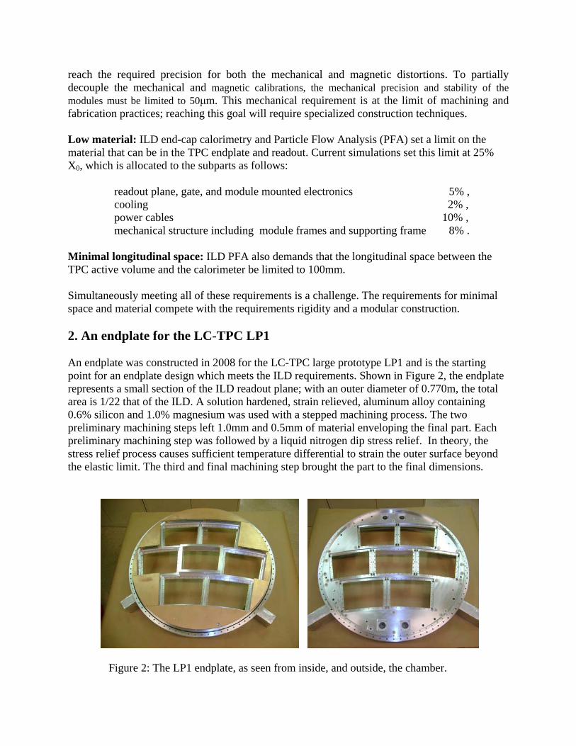
Minimal longitudinal space: ILD PFA also demands that the longitudinal space between the TPC active volume and the calorimeter be limited to 100mm. Simultaneously meeting all of these requirements is a challenge. The requirements for minimal space and material compete with the requirements rigidity and a modular construction. 2. An endplate for the LC-TPC LP1 An endplate was constructed in 2008 for the LC-TPC large prototype LP1 and is the starting point for an endplate design which meets the ILD requirements. Shown in Figure 2, the endplate represents a small section of the ILD readout plane; with an outer diameter of 0.770m, the total area is 1/22 that of the ILD. A solution hardened, strain relieved, aluminum alloy containing 0.6% silicon and 1.0% magnesium was used with a stepped machining process. The two preliminary machining steps left 1.0mm and 0.5mm of material enveloping the final part. Each preliminary machining step was followed by a liquid nitrogen dip stress relief. In theory, the stress relief process causes sufficient temperature differential to strain the outer surface beyond the elastic limit. The third and final machining step brought the part to the final dimensions.
Figure 2: The LP1 endplate, as seen from inside, and outside, the chamber.
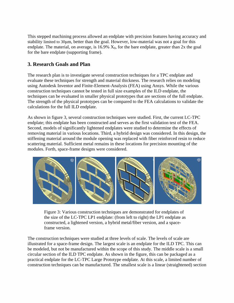
This stepped machining process allowed an endplate with precision features having accuracy and stability limited to 30μm, better than the goal. However, low-material was not a goal for this endplate. The material, on average, is 16.9% X0, for the bare endplate, greater than 2x the goal for the bare endplate (supporting frame). 3. Research Goals and Plan The research plan is to investigate several construction techniques for a TPC endplate and evaluate these techniques for strength and material thickness. The research relies on modeling using Autodesk Inventor and Finite-Element-Analysis (FEA) using Ansys. While the various construction techniques cannot be tested in full size examples of the ILD endplate, the techniques can be evaluated in smaller physical prototypes that are sections of the full endplate. The strength of the physical prototypes can be compared to the FEA calculations to validate the calculations for the full ILD endplate. As shown in figure 3, several construction techniques were studied. First, the current LC-TPC endplate; this endplate has been constructed and serves as the first validation test of the FEA. Second, models of significantly lightened endplates were studied to determine the effects of removing material in various locations. Third, a hybrid design was considered. In this design, the stiffening material around the module opening was replaced with fiber reinforced resin to reduce scattering material. Sufficient metal remains in these locations for precision mounting of the modules. Forth, space-frame designs were considered.
Figure 3: Various construction techniques are demonstrated for endplates of the size of the LC-TPC LP1 endplate: (from left to right) the LP1 endplate as constructed, a lightened version, a hybrid metal/fiber version, and a space-frame version.
The construction techniques were studied at three levels of scale. The levels of scale are illustrated for a space-frame design. The largest scale is an endplate for the ILD TPC. This can be modeled, but not be manufactured within the scope of this study. The middle scale is a small circular section of the ILD TPC endplate. As shown in the figure, this can be packaged as a practical endplate for the LC-TPC Large Prototype endplate. At this scale, a limited number of construction techniques can be manufactured. The smallest scale is a linear (straightened) section
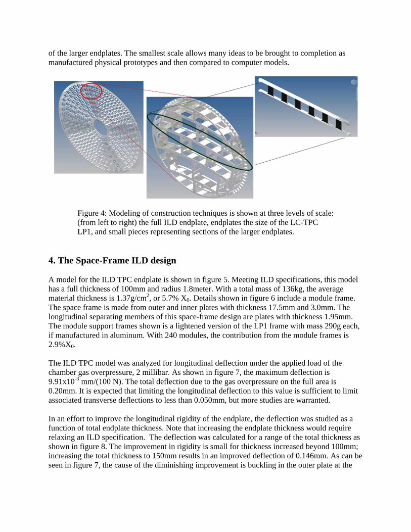
of the larger endplates. The smallest scale allows many ideas to be brought to completion as manufactured physical prototypes and then compared to computer models.
Figure 4: Modeling of construction techniques is shown at three levels of scale: (from left to right) the full ILD endplate, endplates the size of the LC-TPC LP1, and small pieces representing sections of the larger endplates.
4. The Space-Frame ILD design A model for the ILD TPC endplate is shown in figure 5. Meeting ILD specifications, this model has a full thickness of 100mm and radius 1.8meter. With a total mass of 136kg, the average material thickness is 1.37g/cm2, or 5.7% X0. Details shown in figure 6 include a module frame. The space frame is made from outer and inner plates with thickness 17.5mm and 3.0mm. The longitudinal separating members of this space-frame design are plates with thickness 1.95mm. The module support frames shown is a lightened version of the LP1 frame with mass 290g each, if manufactured in aluminum. With 240 modules, the contribution from the module frames is 2.9%X0. The ILD TPC model was analyzed for longitudinal deflection under the applied load of the chamber gas overpressure, 2 millibar. As shown in figure 7, the maximum deflection is 9.91x10⁻³ mm/(100 N). The total deflection due to the gas overpressure on the full area is 0.20mm. It is expected that limiting the longitudinal deflection to this value is sufficient to limit associated transverse deflections to less than 0.050mm, but more studies are warranted. In an effort to improve the longitudinal rigidity of the endplate, the deflection was studied as a function of total endplate thickness. Note that increasing the endplate thickness would require relaxing an ILD specification. The deflection was calculated for a range of the total thickness as shown in figure 8. The improvement in rigidity is small for thickness increased beyond 100mm; increasing the total thickness to 150mm results in an improved deflection of 0.146mm. As can be seen in figure 7, the cause of the diminishing improvement is buckling in the outer plate at the
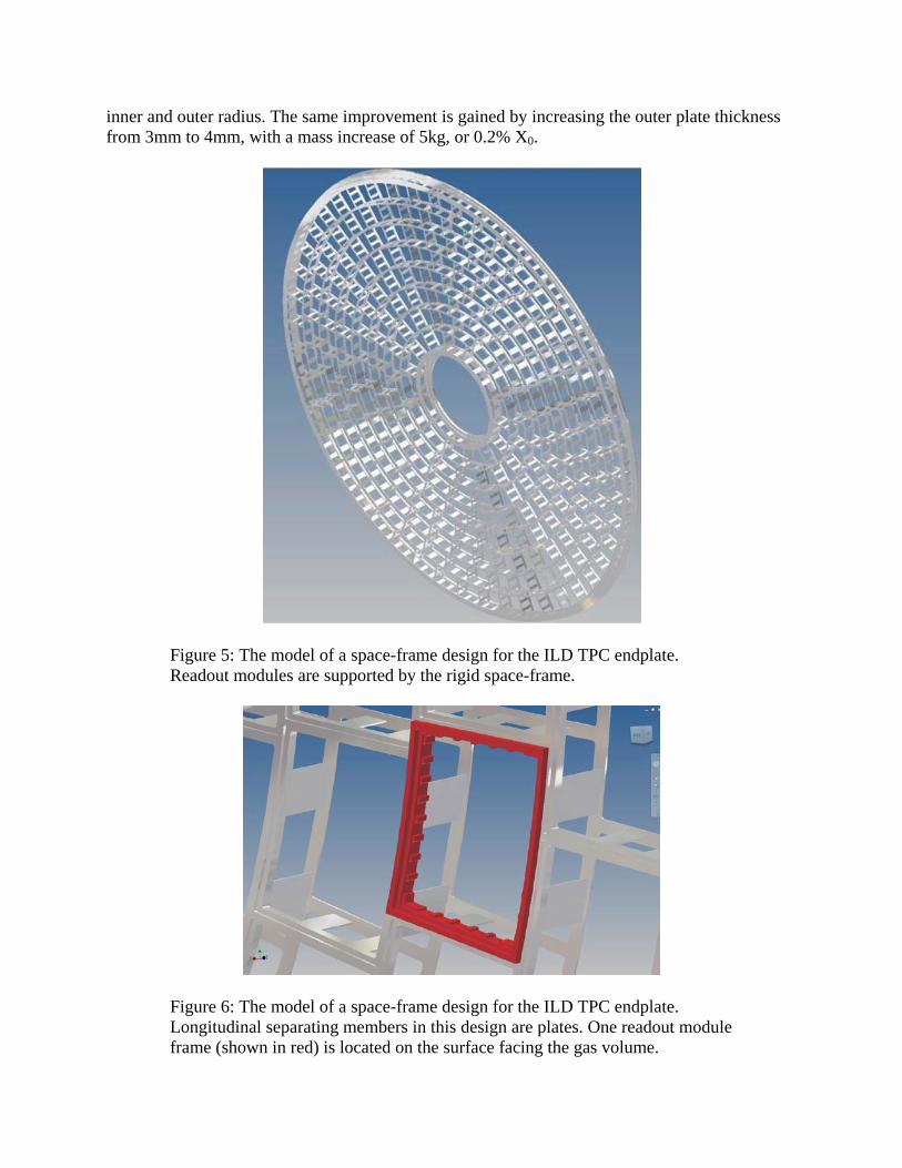
inner and outer radius. The same improvement is gained by increasing the outer plate thickness from 3mm to 4mm, with a mass increase of 5kg, or 0.2% X0.
Figure 5: The model of a space-frame design for the ILD TPC endplate. Readout modules are supported by the rigid space-frame.
Figure 6: The model of a space-frame design for the ILD TPC endplate. Longitudinal separating members in this design are plates. One readout module frame (shown in red) is located on the surface facing the gas volume.
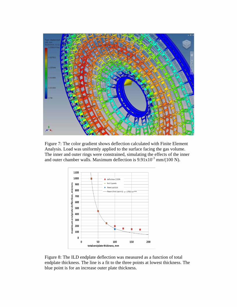
Figure 7: The color gradient shows deflection calculated with Finite Element Analysis. Load was uniformly applied to the surface facing the gas volume. The inner and outer rings were constrained, simulating the effects of the inner and outer chamber walls. Maximum deflection is 9.91x10⁻³ mm/(100 N).
Figure 8: The ILD endplate deflection was measured as a function of total endplate thickness. The line is a fit to the three points at lowest thickness. The blue point is for an increase outer plate thickness.
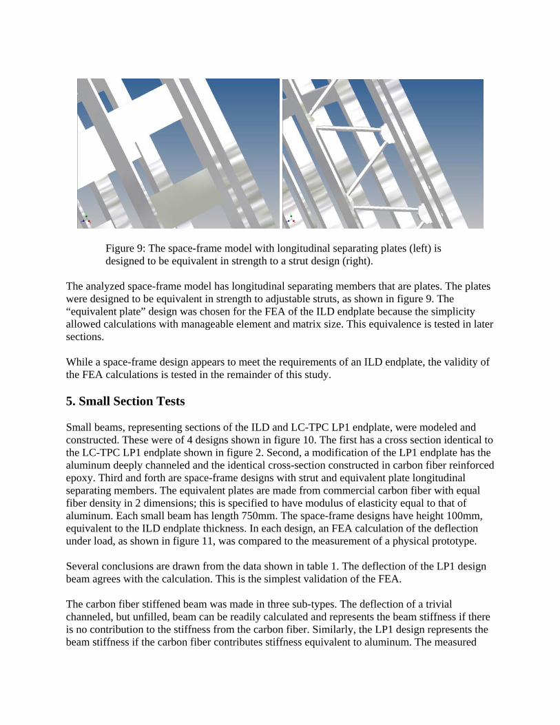
Figure 9: The space-frame model with longitudinal separating plates (left) is designed to be equivalent in strength to a strut design (right).
The analyzed space-frame model has longitudinal separating members that are plates. The plates were designed to be equivalent in strength to adjustable struts, as shown in figure 9. The “equivalent plate” design was chosen for the FEA of the ILD endplate because the simplicity allowed calculations with manageable element and matrix size. This equivalence is tested in later sections. While a space-frame design appears to meet the requirements of an ILD endplate, the validity of the FEA calculations is tested in the remainder of this study. 5. Small Section Tests Small beams, representing sections of the ILD and LC-TPC LP1 endplate, were modeled and constructed. These were of 4 designs shown in figure 10. The first has a cross section identical to the LC-TPC LP1 endplate shown in figure 2. Second, a modification of the LP1 endplate has the aluminum deeply channeled and the identical cross-section constructed in carbon fiber reinforced epoxy. Third and forth are space-frame designs with strut and equivalent plate longitudinal separating members. The equivalent plates are made from commercial carbon fiber with equal fiber density in 2 dimensions; this is specified to have modulus of elasticity equal to that of aluminum. Each small beam has length 750mm. The space-frame designs have height 100mm, equivalent to the ILD endplate thickness. In each design, an FEA calculation of the deflection under load, as shown in figure 11, was compared to the measurement of a physical prototype. Several conclusions are drawn from the data shown in table 1. The deflection of the LP1 design beam agrees with the calculation. This is the simplest validation of the FEA. The carbon fiber stiffened beam was made in three sub-types. The deflection of a trivial channeled, but unfilled, beam can be readily calculated and represents the beam stiffness if there is no contribution to the stiffness from the carbon fiber. Similarly, the LP1 design represents the beam stiffness if the carbon fiber contributes stiffness equivalent to aluminum. The measured
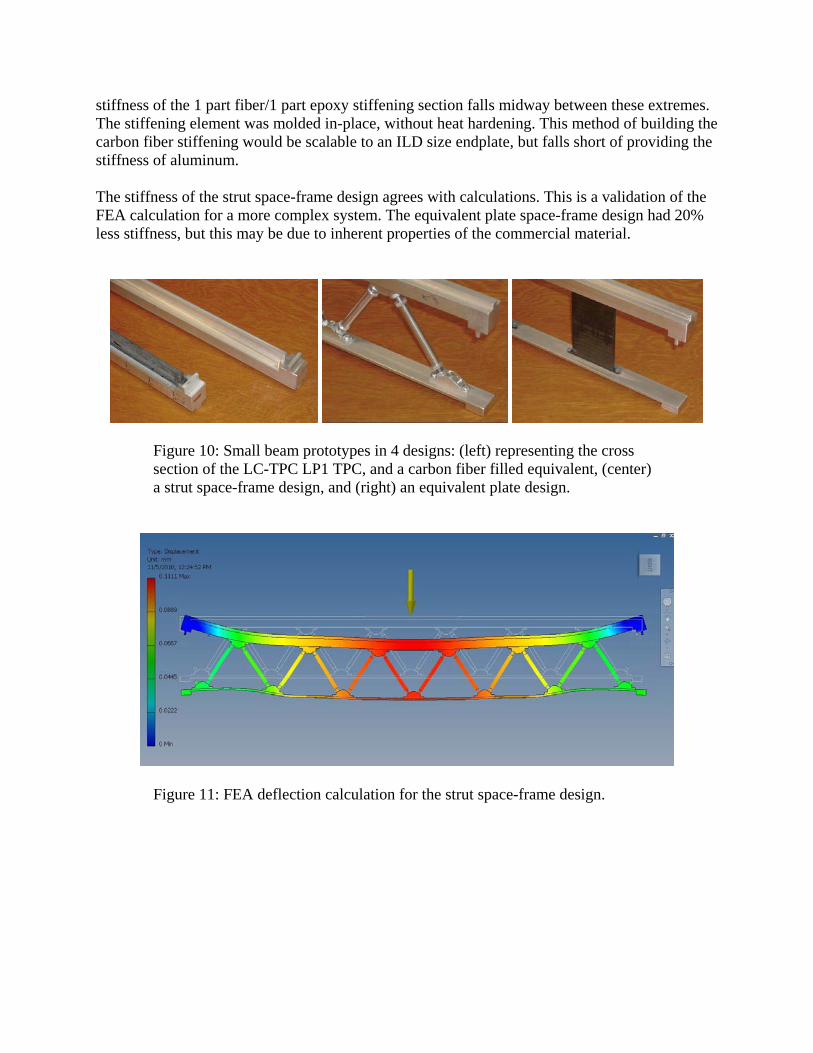
stiffness of the 1 part fiber/1 part epoxy stiffening section falls midway between these extremes. The stiffening element was molded in-place, without heat hardening. This method of building the carbon fiber stiffening would be scalable to an ILD size endplate, but falls short of providing the stiffness of aluminum. The stiffness of the strut space-frame design agrees with calculations. This is a validation of the FEA calculation for a more complex system. The equivalent plate space-frame design had 20% less stiffness, but this may be due to inherent properties of the commercial material.
Figure 10: Small beam prototypes in 4 designs: (left) representing the cross section of the LC-TPC LP1 TPC, and a carbon fiber filled equivalent, (center) a strut space-frame design, and (right) an equivalent plate design.
Figure 11: FEA deflection calculation for the strut space-frame design.
design FEA deflection mm/100N load
measured deflection mm/100N load
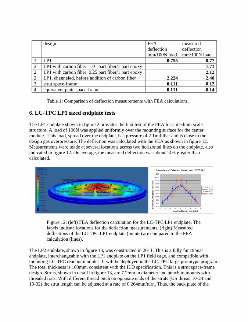
1 LP1 0.755 0.77 2 LP1 with carbon fiber. 1.0 part fiber/1 part epoxy 1.71 2 LP1 with carbon fiber. 0.25 part fiber/1 part epoxy 2.12 2 LP1, channeled, before addition of carbon fiber 2.224 2.40 3 strut space-frame 0.111 0.12 4 equivalent plate space-frame 0.111 0.14
Table 1: Comparison of deflection measurements with FEA calculations.
6. LC-TPC LP1 sized endplate tests The LP1 endplate shown in figure 2 provides the first test of the FEA for a medium scale structure. A load of 100N was applied uniformly over the mounting surface for the center module. This load, spread over the endplate, is a pressure of 2.1millibar and is close to the design gas overpressure. The deflection was calculated with the FEA as shown in figure 12. Measurements were made at several locations across two horizontal lines on the endplate, also indicated in figure 12. On average, the measured deflection was about 14% greater than calculated.
Figure 12: (left) FEA deflection calculation for the LC-TPC LP1 endplate. The labels indicate locations for the deflection measurements. (right) Measured deflections of the LC-TPC LP1 endplate (points) are compared to the FEA calculation (lines).
The LP2 endplate, shown in figure 13, was constructed in 2011. This is a fully functional endplate, interchangeable with the LP1 endplate on the LP1 field cage, and compatible with mounting LC-TPC readout modules. It will be deployed in the LC-TPC large prototype program. The total thickness is 100mm, consistent with the ILD specification. This is a strut space-frame design. Struts, shown in detail in figure 13, are 7.2mm in diameter and attach to mounts with threaded rods. With different thread pitch on opposite ends of the struts (US thread 10-24 and 10-32) the strut length can be adjusted at a rate of 0.264mm/turn. Thus, the back plate of the
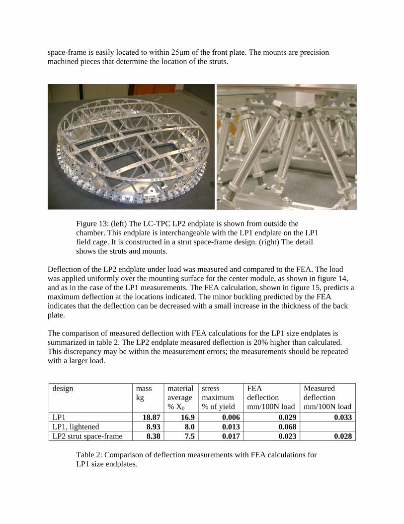
space-frame is easily located to within 25μm of the front plate. The mounts are precision machined pieces that determine the location of the struts.
Figure 13: (left) The LC-TPC LP2 endplate is shown from outside the chamber. This endplate is interchangeable with the LP1 endplate on the LP1 field cage. It is constructed in a strut space-frame design. (right) The detail shows the struts and mounts.
Deflection of the LP2 endplate under load was measured and compared to the FEA. The load was applied uniformly over the mounting surface for the center module, as shown in figure 14, and as in the case of the LP1 measurements. The FEA calculation, shown in figure 15, predicts a maximum deflection at the locations indicated. The minor buckling predicted by the FEA indicates that the deflection can be decreased with a small increase in the thickness of the back plate. The comparison of measured deflection with FEA calculations for the LP1 size endplates is summarized in table 2. The LP2 endplate measured deflection is 20% higher than calculated. This discrepancy may be within the measurement errors; the measurements should be repeated with a larger load.
design mass kg
material average % X0
stress maximum % of yield
FEA deflection mm/100N load
Measured deflection mm/100N load
LP1 18.87 16.9 0.006 0.029 0.033 LP1, lightened 8.93 8.0 0.013 0.068 LP2 strut space-frame 8.38 7.5 0.017 0.023 0.028
Table 2: Comparison of deflection measurements with FEA calculations for LP1 size endplates.
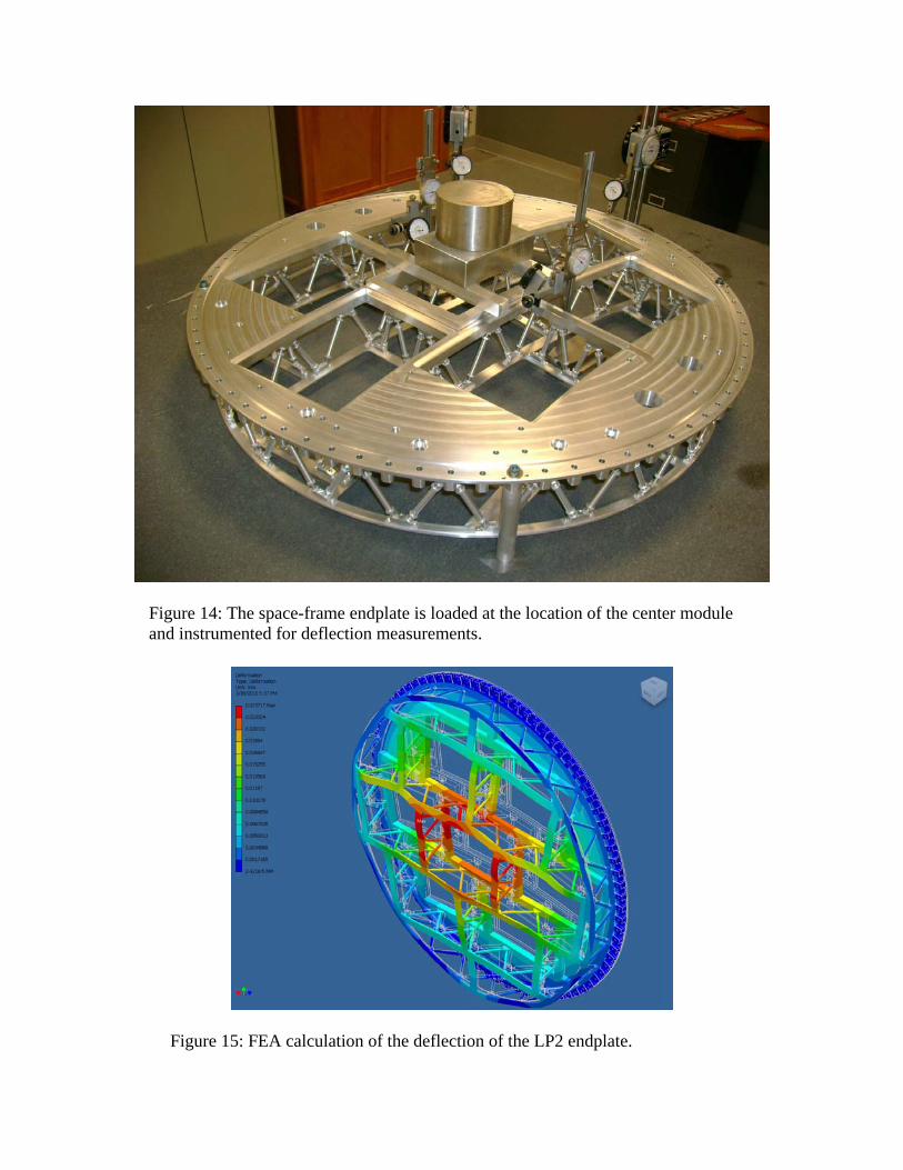
Figure 14: The space-frame endplate is loaded at the location of the center module and instrumented for deflection measurements.
Figure 15: FEA calculation of the deflection of the LP2 endplate.
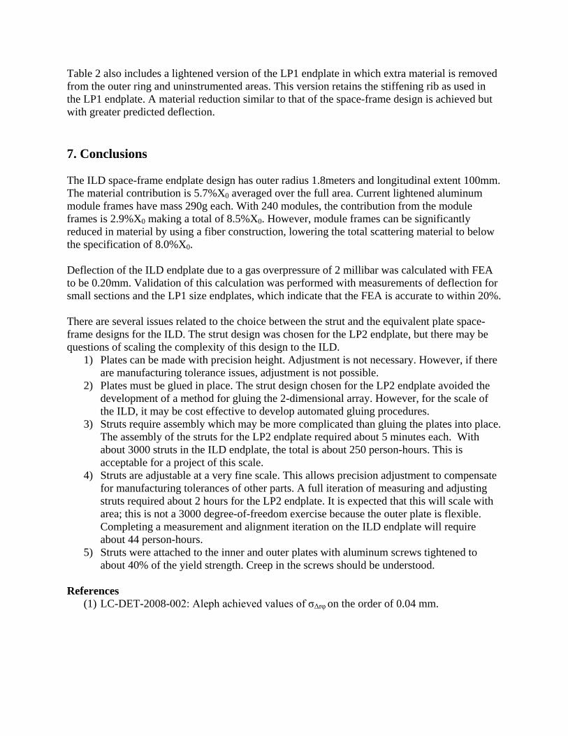
Table 2 also includes a lightened version of the LP1 endplate in which extra material is removed from the outer ring and uninstrumented areas. This version retains the stiffening rib as used in the LP1 endplate. A material reduction similar to that of the space-frame design is achieved but with greater predicted deflection. 7. Conclusions The ILD space-frame endplate design has outer radius 1.8meters and longitudinal extent 100mm. The material contribution is 5.7%X0 averaged over the full area. Current lightened aluminum module frames have mass 290g each. With 240 modules, the contribution from the module frames is 2.9%X0 making a total of 8.5%X0. However, module frames can be significantly reduced in material by using a fiber construction, lowering the total scattering material to below the specification of 8.0%X0. Deflection of the ILD endplate due to a gas overpressure of 2 millibar was calculated with FEA to be 0.20mm. Validation of this calculation was performed with measurements of deflection for small sections and the LP1 size endplates, which indicate that the FEA is accurate to within 20%. There are several issues related to the choice between the strut and the equivalent plate space-frame designs for the ILD. The strut design was chosen for the LP2 endplate, but there may be questions of scaling the complexity of this design to the ILD.
1) Plates can be made with precision height. Adjustment is not necessary. However, if there are manufacturing tolerance issues, adjustment is not possible.
2) Plates must be glued in place. The strut design chosen for the LP2 endplate avoided the development of a method for gluing the 2-dimensional array. However, for the scale of the ILD, it may be cost effective to develop automated gluing procedures.
3) Struts require assembly which may be more complicated than gluing the plates into place. The assembly of the struts for the LP2 endplate required about 5 minutes each. With about 3000 struts in the ILD endplate, the total is about 250 person-hours. This is acceptable for a project of this scale.
4) Struts are adjustable at a very fine scale. This allows precision adjustment to compensate for manufacturing tolerances of other parts. A full iteration of measuring and adjusting struts required about 2 hours for the LP2 endplate. It is expected that this will scale with area; this is not a 3000 degree-of-freedom exercise because the outer plate is flexible. Completing a measurement and alignment iteration on the ILD endplate will require about 44 person-hours.
5) Struts were attached to the inner and outer plates with aluminum screws tightened to about 40% of the yield strength. Creep in the screws should be understood.
References
(1) LC-DET-2008-002: Aleph achieved values of σΔrφ on the order of 0.04 mm.