Catalogo generale UK - bk-systems-germany.de · fhm 006 - 007 1,50 1,00 0,50 0,00 0 20 40 60 80 100
12
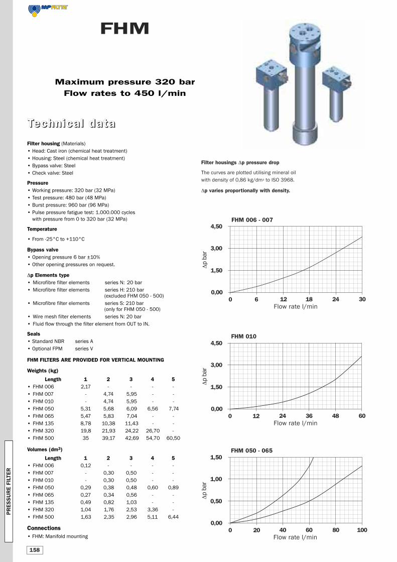
4,50 3,00 1,50 0,00 0 12 24 36 48 60 Δp bar Flow rate l/min 4,50 3,00 1,50 0,00 0 6 12 18 24 30 Δp bar Flow rate l/min FHM 006 - 007 1,50 1,00 0,50 0,00 0 20 40 60 80 100 Δp bar Flow rate l/min FHM 010 FHM 050 - 065 FHM Filter housing (Materials) • Head: Cast iron (chemical heat treatment) • Housing: Steel (chemical heat treatment) • Bypass valve: Steel • Check valve: Steel Pressure • Working pressure: 320 bar (32 MPa) • Test pressure: 480 bar (48 MPa) • Burst pressure: 960 bar (96 MPa) • Pulse pressure fatigue test: 1.000.000 cycles with pressure from 0 to 320 bar (32 MPa) Temperature • From -25°C to +110°C Bypass valve • Opening pressure 6 bar ±10% • Other opening pressures on request. Δp Elements type • Microfibre filter elements series N: 20 bar • Microfibre filter elements series H: 210 bar (excluded FHM 050 - 500) • Microfibre filter elements series S: 210 bar (only for FHM 050 - 500) • Wire mesh filter elements series N: 20 bar • Fluid flow through the filter element from OUT to IN. Seals • Standard NBR series A • Optional FPM series V FHM FILTERS ARE PROVIDED FOR VERTICAL MOUNTING Weights (kg) Length 1 2 3 4 5 • FHM 006 2,17 - - - - • FHM 007 - 4,74 5,95 - - • FHM 010 - 4,74 5,95 - - • FHM 050 5,31 5,68 6,09 6,56 7,74 • FHM 065 5,47 5,83 7,04 - - • FHM 135 8,78 10,38 11,43 - - • FHM 320 19,8 21,93 24,22 26,70 - • FHM 500 35 39,17 42,69 54,70 60,50 Volumes (dm 3 ) Length 1 2 3 4 5 • FHM 006 0,12 - - - - • FHM 007 - 0,30 0,50 - - • FHM 010 - 0,30 0,50 - - • FHM 050 0,29 0,38 0,48 0,60 0,89 • FHM 065 0,27 0,34 0,56 - - • FHM 135 0,49 0,82 1,03 - - • FHM 320 1,04 1,76 2,53 3,36 - • FHM 500 1,63 2,35 2,96 5,11 6,44 Connections • FHM: Manifold mounting Filter housings Δp pressure drop The curves are plotted utilising mineral oil with density of 0,86 kg/dm 3 to ISO 3968. Δp varies proportionally with density. Maximum pressure 320 bar Flow rates to 450 l/min T T e e c c h h n n i i c c a a l l d d a a t t a a PRESSURE FILTER 158
Transcript of Catalogo generale UK - bk-systems-germany.de · fhm 006 - 007 1,50 1,00 0,50 0,00 0 20 40 60 80 100
4,50
3,00
1,50
0,000 12 24 36 48 60
Δp b
ar
Flow rate l/min
4,50
3,00
1,50
0,000 6 12 18 24 30
Δp b
ar
Flow rate l/min
FHM 006 - 007
1,50
1,00
0,50
0,000 20 40 60 80 100
Δp b
ar
Flow rate l/min
FHM 010
FHM 050 - 065
FHM
Filter housing (Materials)
• Head: Cast iron (chemical heat treatment)
• Housing: Steel (chemical heat treatment)
• Bypass valve: Steel
• Check valve: Steel
Pressure• Working pressure: 320 bar (32 MPa)
• Test pressure: 480 bar (48 MPa)
• Burst pressure: 960 bar (96 MPa)
• Pulse pressure fatigue test: 1.000.000 cycles
with pressure from 0 to 320 bar (32 MPa)
Temperature
• From -25°C to +110°C
Bypass valve• Opening pressure 6 bar ±10%
• Other opening pressures on request.
Δp Elements type• Microfibre filter elements series N: 20 bar
• Microfibre filter elements series H: 210 bar
(excluded FHM 050 - 500)
• Microfibre filter elements series S: 210 bar
(only for FHM 050 - 500)
• Wire mesh filter elements series N: 20 bar
• Fluid flow through the filter element from OUT to IN.
Seals• Standard NBR series A
• Optional FPM series V
FHM FILTERS ARE PROVIDED FOR VERTICAL MOUNTING
Weights (kg)
Length 1 2 3 4 5• FHM 006 2,17 - - - -
• FHM 007 - 4,74 5,95 - -
• FHM 010 - 4,74 5,95 - -
• FHM 050 5,31 5,68 6,09 6,56 7,74
• FHM 065 5,47 5,83 7,04 - -
• FHM 135 8,78 10,38 11,43 - -
• FHM 320 19,8 21,93 24,22 26,70 -
• FHM 500 35 39,17 42,69 54,70 60,50
Volumes (dm3)
Length 1 2 3 4 5• FHM 006 0,12 - - - -
• FHM 007 - 0,30 0,50 - -
• FHM 010 - 0,30 0,50 - -
• FHM 050 0,29 0,38 0,48 0,60 0,89
• FHM 065 0,27 0,34 0,56 - -
• FHM 135 0,49 0,82 1,03 - -
• FHM 320 1,04 1,76 2,53 3,36 -
• FHM 500 1,63 2,35 2,96 5,11 6,44
Connections• FHM: Manifold mounting
Filter housings Δp pressure drop
The curves are plotted utilising mineral oil
with density of 0,86 kg/dm3 to ISO 3968.
Δp varies proportionally with density.
Maximum pressure 320 bar
Flow rates to 450 l/min
TTeecchhnniiccaall ddaattaa
PR
ES
SU
RE
FIL
TER
158
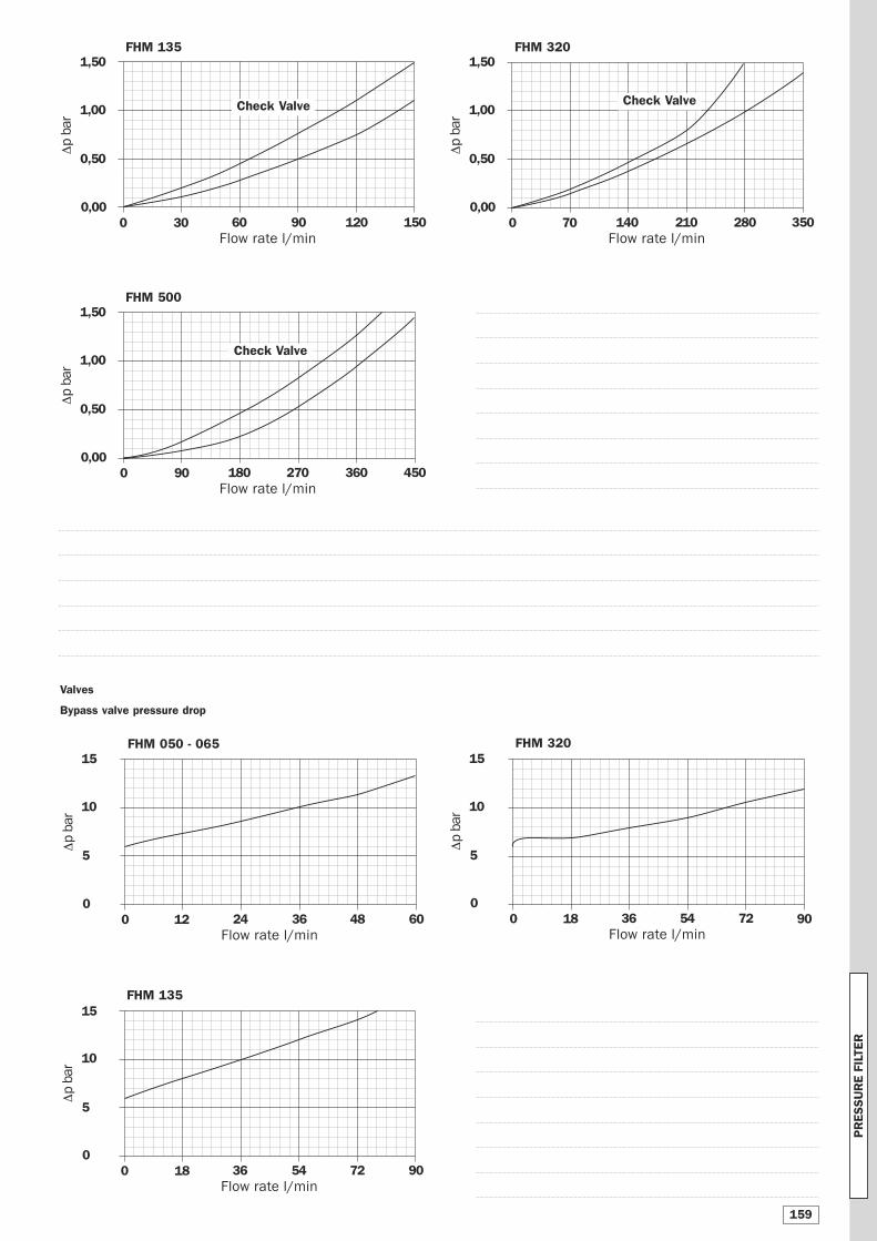
Valves
Bypass valve pressure drop
15
10
5
00 18 36 54 72 90
Δp b
ar
Flow rate l/min
15
10
5
00 12 24 36 48 60
Δp b
ar
Flow rate l/min
FHM 050 - 065
FHM 135
15
10
5
00 18 36 54 72 90
Δp b
ar
Flow rate l/min
FHM 320
1,50
1,00
0,50
0,000 30 60 90 120 150
Δp b
ar
Flow rate l/min
FHM 135
Check Valve
1,50
1,00
0,50
0,000 70 140 210 280 350
Δp b
ar
Flow rate l/min
FHM 320
Check Valve
1,50
1,00
0,50
0,000 90 180 270 360 450
Δp b
ar
Flow rate l/min
FHM 500
Check Valve
PR
ESSU
RE F
ILTE
R
159
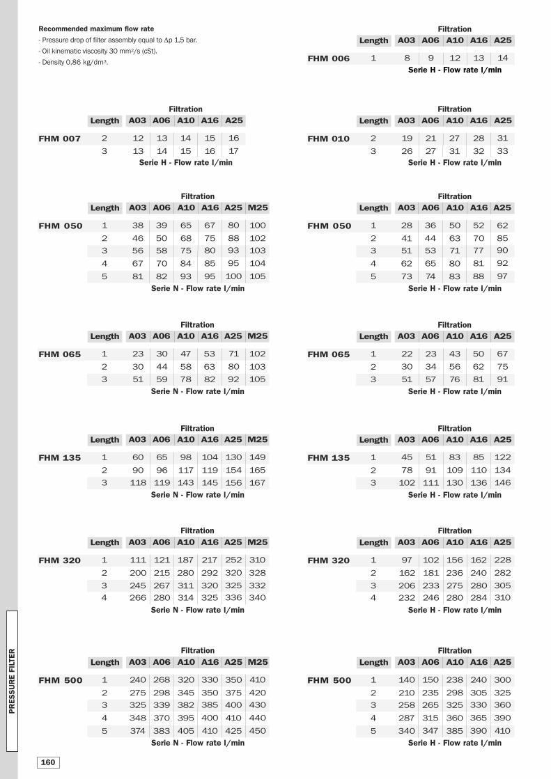
Recommended maximum flow rate
- Pressure drop of filter assembly equal to Δp 1,5 bar.
- Oil kinematic viscosity 30 mm2/s (cSt).
- Density 0,86 kg/dm3.
Serie H - Flow rate l/min
A03 A06 A10 A16 A25Length
19
26
21
27
27
31
28
32
2
3
31
33
FHM 010
Serie N - Flow rate l/min
A03 A06 A10 A16 A25 M25Length
51 59 78 82 1053 92
23
30
30
44
47
58
53
63
102
103
1
2
71
80
FHM 065
Serie H - Flow rate l/min
A03 A06 A10 A16 A25Length
51 57 76 813 91
22
30
23
34
43
56
50
62
1
2
67
75
FHM 065
Serie N - Flow rate l/min
A03 A06 A10 A16 A25 M25Length
111
200
121
215
187
280
217
292
310
328
1
2
252
320
FHM 320
245
266
267
280
311
314
320
325
332
340
3
4
325
336
Serie H - Flow rate l/min
A03 A06 A10 A16 A25Length
97
162
102
181
156
236
162
240
1
2
228
282
FHM 320
206
232
233
246
275
280
280
284
3
4
305
310
Serie N - Flow rate l/min
A03 A06 A10 A16 A25 M25Length
56
67
81
58
70
82
75
84
93
80
85
95
103
104
105
3
4
5
38
46
39
50
65
68
67
75
100
102
1
2
80
88
FHM 050
Serie H - Flow rate l/min
A03 A06 A10 A16 A25Length
51
62
73
53
65
74
71
80
83
77
81
88
3
4
5
90
92
97
28
41
36
44
50
63
52
70
1
2
62
85
FHM 050
Serie N - Flow rate l/min
A03 A06 A10 A16 A25 M25Length
118 119 143 145 1673 156
60
90
65
96
98
117
104
119
149
165
1
2
130
154
FHM 135
Serie H - Flow rate l/min
A03 A06 A10 A16 A25Length
102 111 130 1363 146
45
78
51
91
83
109
85
110
1
2
122
134
FHM 135
Serie N - Flow rate l/min
A03 A06 A10 A16 A25 M25Length
325
348
374
339
370
383
382
395
405
385
400
410
430
440
450
3
4
5
400
410
425
240
275
268
298
320
345
330
350
410
420
1
2
350
375
FHM 500
Serie H - Flow rate l/min
A03 A06 A10 A16 A25Length
258
287
340
265
315
347
325
360
385
330
365
390
3
4
5
360
390
410
140
210
150
235
238
298
240
305
1
2
300
325
FHM 500
93
95
100
Serie H - Flow rate l/min
A03 A06 A10 A16 A25Length
8 9 12 131 14FHM 006
Serie H - Flow rate l/min
A03 A06 A10 A16 A25Length
12
13
13
14
14
15
15
16
2
3
16
17
FHM 007
Filtration
Filtration
Filtration
FiltrationFiltration
FiltrationFiltration
FiltrationFiltration
FiltrationFiltration
FiltrationFiltration
PR
ESSU
RE F
ILTE
R
160
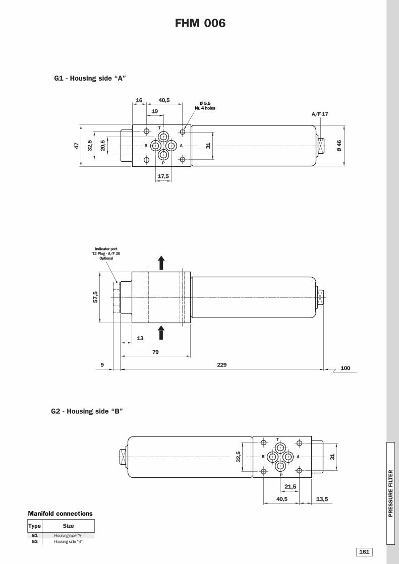
16
17,5
Ø 4
6
FHM 006
40,5
47 20,5
32,5
G1 - Housing side “A”
31
13,540,5
31
G2 - Housing side “B”
32,5
13
57,5
9
79
229
P
T
B A
P
AB
19
21,5
T
Manifold connections
Size
G1G2
Housing side “A”
Housing side “B”
Type
Indicator portT2 Plug - A/F 30
Optional
Ø 5,5Nr. 4 holes
A/F 17
100
PR
ESSU
RE F
ILTE
R
161
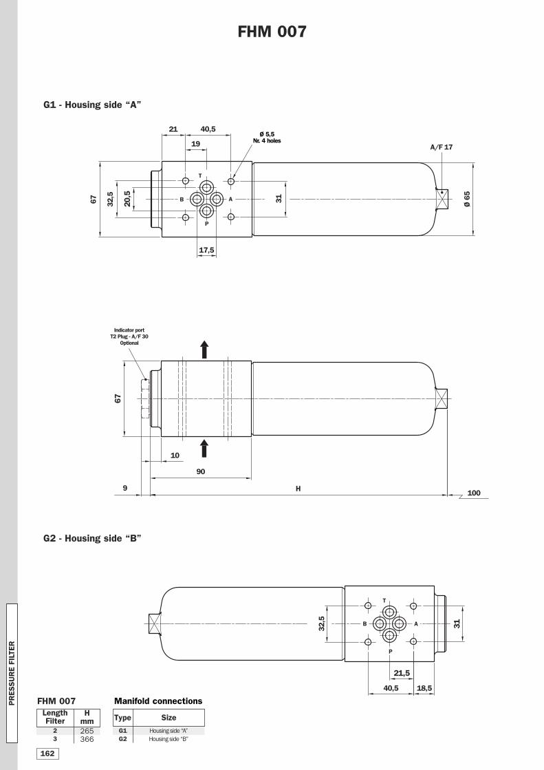
17,5
20,5
21
Ø 6
5
FHM 007
67 32,5
G1 - Housing side “A”
31
3132,5
40,5
G2 - Housing side “B”
10
67
9
90
H
LengthFilter
Hmm
23
265366
T
40,5
18,5
19
P
AB
T
B A
P
21,5
FHM 007 Manifold connections
Size
G1G2
Housing side “A”
Housing side “B”
Type
Indicator portT2 Plug - A/F 30
Optional
Ø 5,5Nr. 4 holes
A/F 17
100
PR
ESSU
RE F
ILTE
R
162
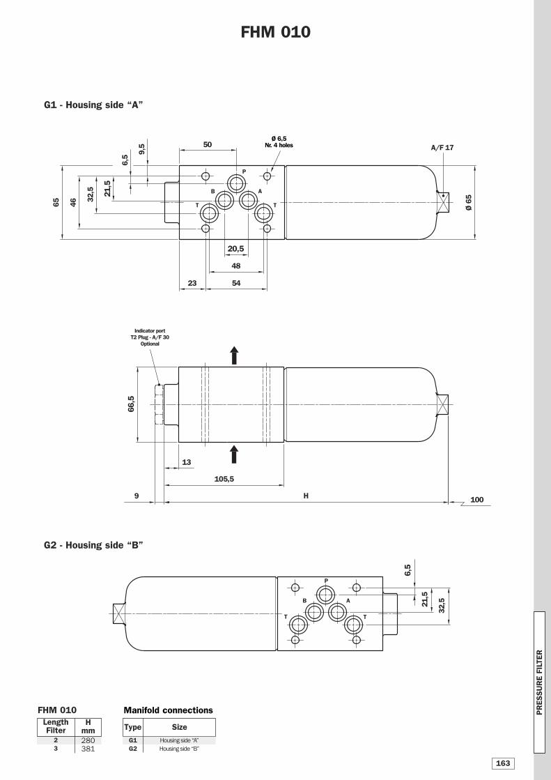
6,5
21,5
20,5
23
Ø 6
5
FHM 010
50
65
32,5
46
G1 - Housing side “A”
48
9,5
G2 - Housing side “B”
13
66,5
105,5
H 100
LengthFilter
Hmm
23
280381
54
6,5
21,5
32,5
T
B A
P
T
T
B A
P
T
FHM 010
9
Manifold connections
Size
G1G2
Housing side “A”
Housing side “B”
Type
Indicator portT2 Plug - A/F 30
Optional
Ø 6,5Nr. 4 holes A/F 17
PR
ESSU
RE F
ILTE
R
163
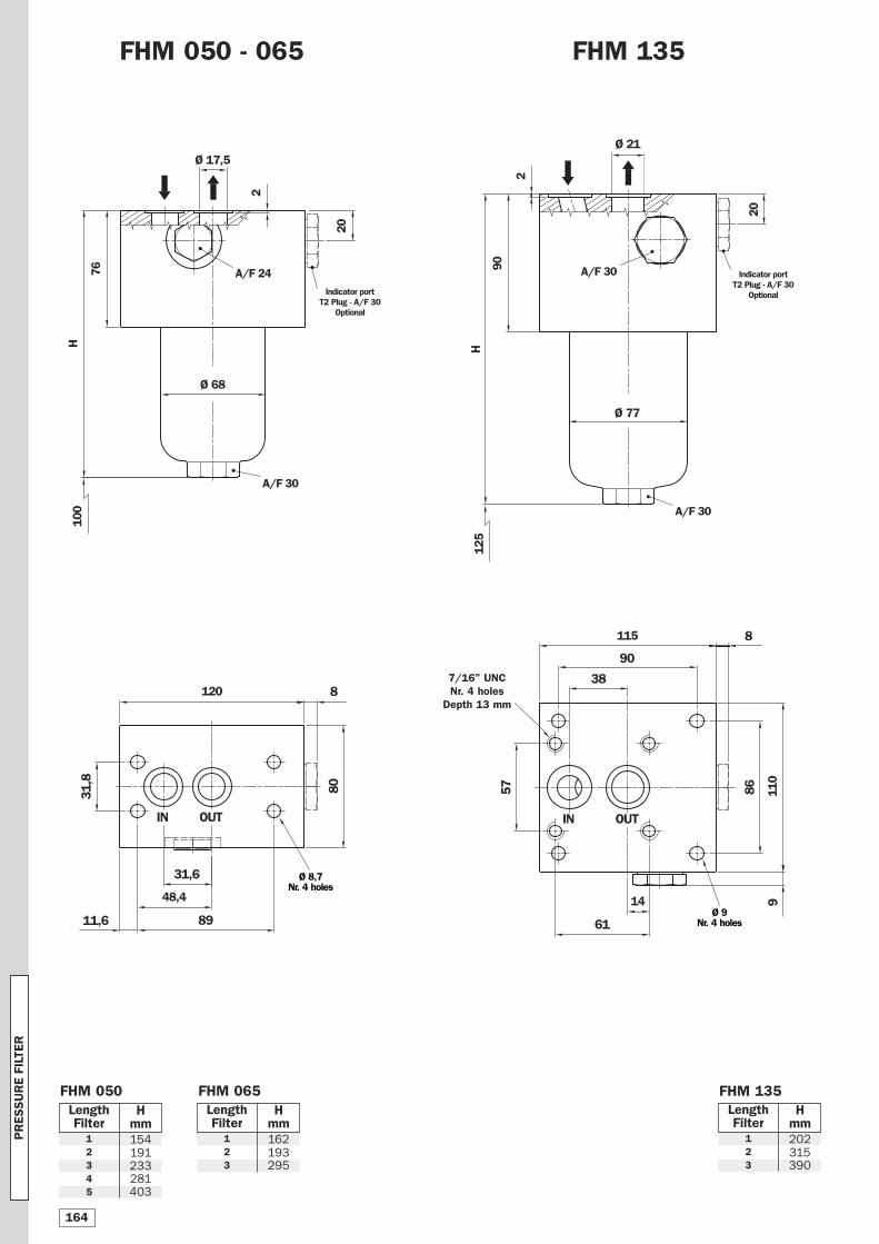
48,4
31,8
31,6
Ø 17,5
FHM 050 - 065
Ø 68
H10
0
76
80
2
120 8
8911,6
IN OUT
LengthFilter
Hmm
12345
154191233281403
FHM 135
14 9
38
Ø 21
Ø 77
H12
5
90
8620
110
115 8
90
61
IN
20
257
7/16” UNCNr. 4 holes
Depth 13 mm
LengthFilter
Hmm
123
202315390
LengthFilter
Hmm
123
162193295
OUT
FHM 050 FHM 065 FHM 135
Indicator portT2 Plug - A/F 30
Optional
Ø 8,7Nr. 4 holes
Ø 9Nr. 4 holes
A/F 30
A/F 30
A/F 24 A/F 30 Indicator portT2 Plug - A/F 30
Optional
PR
ESSU
RE F
ILTE
R
164
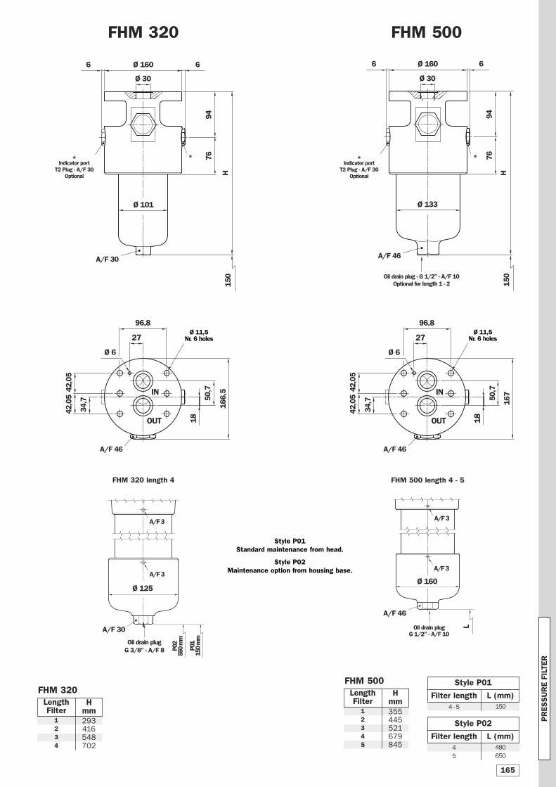
FHM 320
Ø 1606
Ø 10194
6
LengthFilter
Hmm
1234
293416548702
FHM 500
34,7
Ø 1606
Ø 133
167
96,8
Ø 6
18
27
50,7
6
76
IN
OUT
Oil drain plug - G 1/2” - A/F 10Optional for length 1 - 2
LengthFilter
Hmm
Style P01
1504 - 512345
355445521679845
L (mm)Filter length
Style P02
480
650
4
5
L (mm)Filter length
H
P02
550
mm
P01
150
mm
Ø 125
Oil drain plugG 3/8” - A/F 8
FHM 320 length 494
76
H
L
Ø 160
FHM 500 length 4 - 5
Oil drain plugG 1/2” - A/F 10
FHM 500
Ø 30
FHM 320
Style P01 Standard maintenance from head.
Style P02 Maintenance option from housing base.
**
Ø 30
150
150
42,0
542
,05
34,7
166,
5
96,8
Ø 6
18
27
50,7IN
OUT
Ø 11,5Nr. 6 holes
Ø 11,5Nr. 6 holes
A/F 30 A/F 46
A/F 46A/F 46
A/F 46
A/F 30
A/F 3 A/F 3
A/F 3A/F 3
*Indicator port
T2 Plug - A/F 30Optional
*Indicator port
T2 Plug - A/F 30Optional
42,0
542
,05
PR
ESSU
RE F
ILTE
R
165
3e
3d
3a
3b
3c
2
3f
4
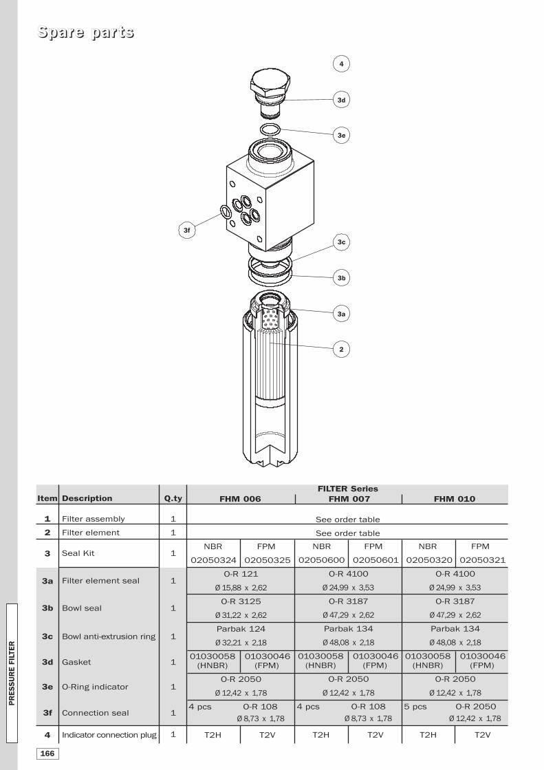
SSppaarree ppaarr ttss
Item
1
2
3
3a
3b
3c
3d
3e
3f
4
Q.ty
1
1
1
1
1
1
1
1
1
1
Description
Filter assembly
Filter element
Seal Kit
Filter element seal
Bowl seal
Bowl anti-extrusion ring
Gasket
O-Ring indicator
Connection seal
Indicator connection plug
FILTER Series FHM 006 FHM 007 FHM 010
See order table
See order table
NBR FPM
02050324 02050325
O-R 121
Ø 15,88 x 2,62
O-R 3125
Ø 31,22 x 2,62
Parbak 124
Ø 32,21 x 2,18
01030058 01030046
(HNBR) (FPM)
O-R 2050
Ø 12,42 x 1,78
4 pcs O-R 108
Ø 8,73 x 1,78
T2H T2V
NBR FPM
02050600 02050601
O-R 4100
Ø 24,99 x 3,53
O-R 3187
Ø 47,29 x 2,62
Parbak 134
Ø 48,08 x 2,18
01030058 01030046
(HNBR) (FPM)
O-R 2050
Ø 12,42 x 1,78
4 pcs O-R 108
Ø 8,73 x 1,78
T2H T2V
NBR FPM
02050320 02050321
O-R 4100
Ø 24,99 x 3,53
O-R 3187
Ø 47,29 x 2,62
Parbak 134
Ø 48,08 x 2,18
01030058 01030046
(HNBR) (FPM)
O-R 2050
Ø 12,42 x 1,78
5 pcs O-R 2050
Ø 12,42 x 1,78
T2H T2V
PR
ESSU
RE F
ILTE
R
166
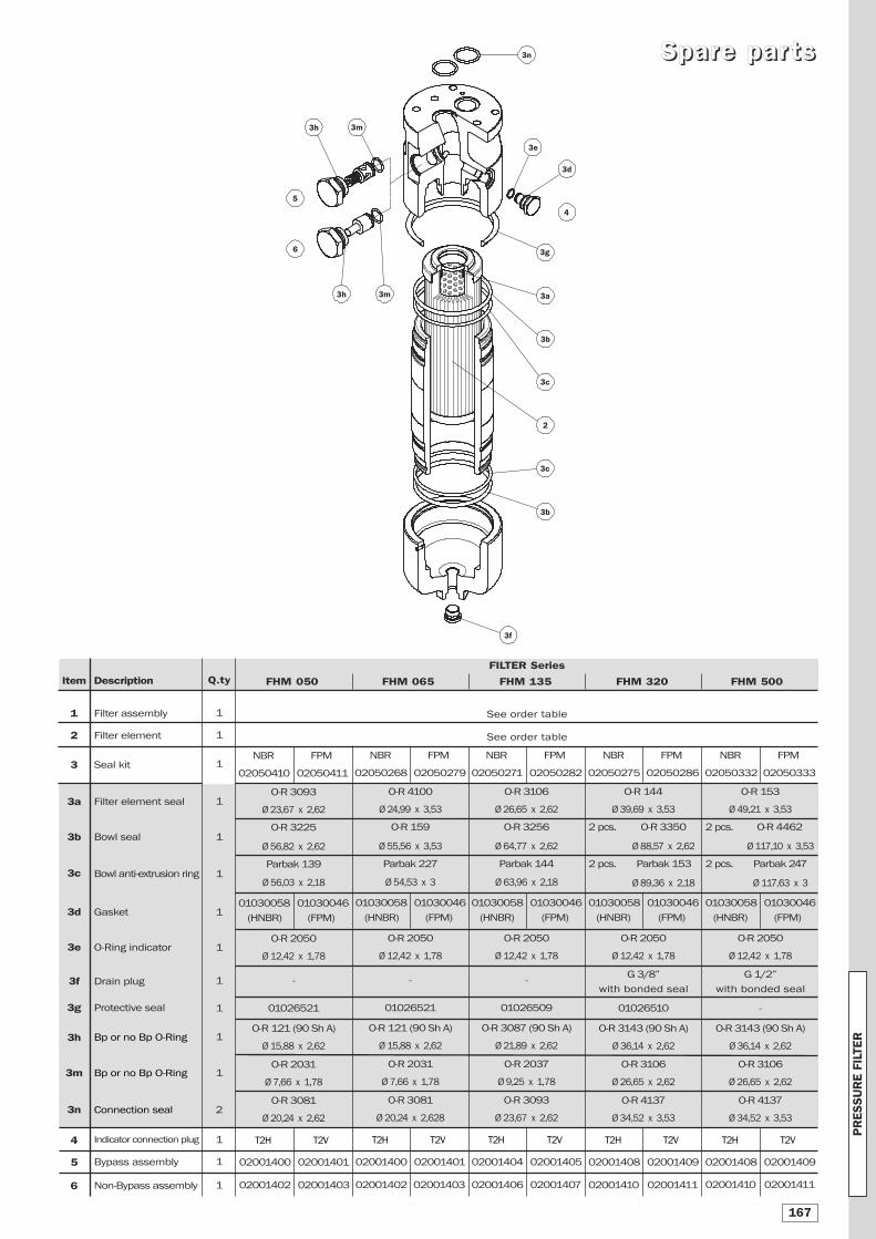
Item
1
2
3
3a
3b
3c
3d
3e
3f
3g
3h
3m
3n
4
5
6
Q.ty
1
1
1
1
1
1
1
1
1
1
1
1
2
1
1
1
Description
Filter assembly
Filter element
Seal kit
Filter element seal
Bowl seal
Bowl anti-extrusion ring
Gasket
O-Ring indicator
Drain plug
Protective seal
Bp or no Bp O-Ring
Bp or no Bp O-Ring
Connection seal
Indicator connection plug
Bypass assembly
Non-Bypass assembly
FILTER Series
FHM 050 FHM 065 FHM 135 FHM 320 FHM 500
See order table
See order table
NBR FPM
02050268 02050279
O-R 4100
Ø 24,99 x 3,53
O-R 159
Ø 55,56 x 3,53
Parbak 227
Ø 54,53 x 3
01030058 01030046
(HNBR) (FPM)
O-R 2050
Ø 12,42 x 1,78
-
01026521
O-R 121 (90 Sh A)
Ø 15,88 x 2,62
O-R 2031
Ø 7,66 x 1,78
O-R 3081
Ø 20,24 x 2,628
T2H T2V
02001400 02001401
02001402 02001403
NBR FPM
02050275 02050286
O-R 144
Ø 39,69 x 3,53
2 pcs. O-R 3350
Ø 88,57 x 2,62
2 pcs. Parbak 153
Ø 89,36 x 2,18
01030058 01030046
(HNBR) (FPM)
O-R 2050
Ø 12,42 x 1,78
G 3/8”
with bonded seal
01026510
O-R 3143 (90 Sh A)
Ø 36,14 x 2,62
O-R 3106
Ø 26,65 x 2,62
O-R 4137
Ø 34,52 x 3,53
T2H T2V
02001408 02001409
02001410 02001411
NBR FPM
02050332 02050333
O-R 153
Ø 49,21 x 3,53
2 pcs. O-R 4462
Ø 117,10 x 3,53
2 pcs. Parbak 247
Ø 117,63 x 3
01030058 01030046
(HNBR) (FPM)
O-R 2050
Ø 12,42 x 1,78
G 1/2”
with bonded seal
-
O-R 3143 (90 Sh A)
Ø 36,14 x 2,62
O-R 3106
Ø 26,65 x 2,62
O-R 4137
Ø 34,52 x 3,53
T2H T2V
02001408 02001409
02001410 02001411
NBR FPM
02050410 02050411
O-R 3093
Ø 23,67 x 2,62
O-R 3225
Ø 56,82 x 2,62
Parbak 139
Ø 56,03 x 2,18
01030058 01030046
(HNBR) (FPM)
O-R 2050
Ø 12,42 x 1,78
-
01026521
O-R 121 (90 Sh A)
Ø 15,88 x 2,62
O-R 2031
Ø 7,66 x 1,78
O-R 3081
Ø 20,24 x 2,62
T2H T2V
02001400 02001401
02001402 02001403
3n
3e
3b
3a
3b
3c
2
3h 3m
5
3g
3f
4
3d
3c
3h 3m
6
SSppaarree ppaarr ttss
NBR FPM
02050271 02050282
O-R 3106
Ø 26,65 x 2,62
O-R 3256
Ø 64,77 x 2,62
Parbak 144
Ø 63,96 x 2,18
01030058 01030046
(HNBR) (FPM)
O-R 2050
Ø 12,42 x 1,78
-
01026509
O-R 3087 (90 Sh A)
Ø 21,89 x 2,62
O-R 2037
Ø 9,25 x 1,78
O-R 3093
Ø 23,67 x 2,62
T2H T2V
02001404 02001405
02001406 02001407
PR
ESSU
RE F
ILTE
R
167

NNootteess
The data in this publication are purely guideline. MP Filtri reserves the right to make changes to the models described herein at any time it deems fit in relation to technical or
commercial requirements. The colours of the products shown on the cover are purely guideline. Copyright. All rights reserved.
PR
ESSU
RE F
ILTE
R
168
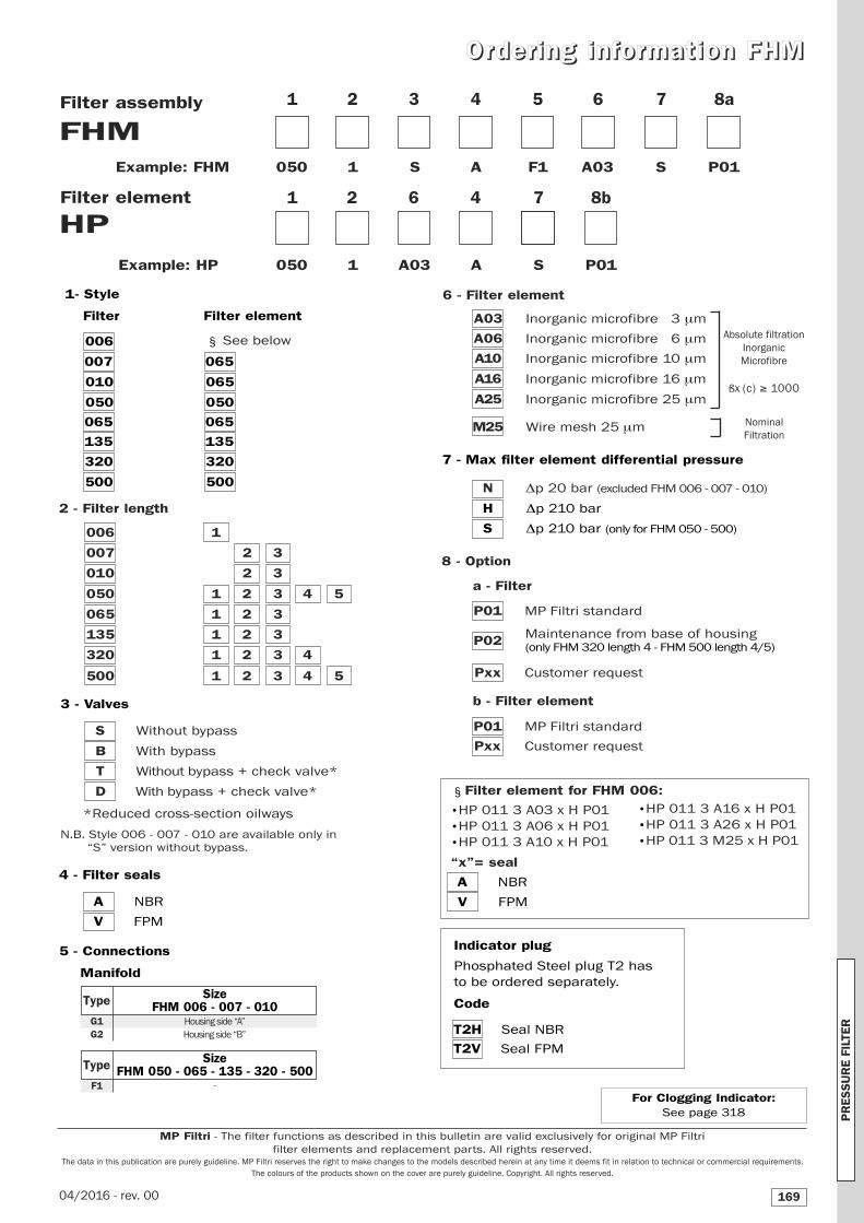
OO rr ddeerr iinngg iinnff oorr mmaatt iioonn FFHHMM
FHM1 2 3 4 5 6
HP
Filter assembly
Example: FHM 050 1 S A F1 A03 S P01
Filter element
7
Example: HP 050 1 A03 A S P01
1 2 6 4
5 - Connections
Manifold
8a
8 - Option
a - Filter
P01 MP Filtri standard
P02
Pxx Customer request
b - Filter element
P01 MP Filtri standard
Pxx Customer request
3 - Valves
S Without bypass
B With bypass
T Without bypass + check valve*
D With bypass + check valve*
*Reduced cross-section oilways
N.B. Style 006 - 007 - 010 are available only in
“S” version without bypass.
7 8b
7 - Max filter element differential pressure
N Δp 20 bar (excluded FHM 006 - 007 - 010)
H Δp 210 bar
S Δp 210 bar (only for FHM 050 - 500)
Maintenance from base of housing(only FHM 320 length 4 - FHM 500 length 4/5)
4 - Filter seals
A NBR
V FPM
1 - Style
Filter Filter element
006
007 065
010 065
050 050
065 065
135 135
320 320
500 500
See below
A NBR
V FPM
SizeFHM 050 - 065 - 135 - 320 - 500
F1
Type
SizeFHM 006 - 007 - 010
G1G2
Housing side “A”
Housing side “B”
Type
§
§ Filter element for FHM 006:
Indicator plug
Phosphated Steel plug T2 has
to be ordered separately.
Code
T2H Seal NBR
T2V Seal FPM
•HP 011 3 A16 x H P01
•HP 011 3 A26 x H P01
•HP 011 3 M25 x H P01
•HP 011 3 A03 x H P01
•HP 011 3 A06 x H P01
•HP 011 3 A10 x H P01
“x”= seal
2 - Filter length
006 1
007 2 3
010 2 3
050 1 2 3 4 5
065 1 2 3
135 1 2 3
320 1 2 3 4
500 1 2 3 4 5
-
Nominal
Filtration
Absolute filtration
Inorganic
Microfibre
ßx (c) ≥ 1000
6 - Filter element
A03 Inorganic microfibre 3 μm
A06 Inorganic microfibre 6 μm
A10 Inorganic microfibre 10 μm
A16 Inorganic microfibre 16 μm
A25 Inorganic microfibre 25 μm
M25 Wire mesh 25 μm
PR
ES
SU
RE
FIL
TER
169
MP Filtri - The filter functions as described in this bulletin are valid exclusively for original MP Filtri
filter elements and replacement parts. All rights reserved.The data in this publication are purely guideline. MP Filtri reserves the right to make changes to the models described herein at any time it deems fit in relation to technical or commercial requirements.
The colours of the products shown on the cover are purely guideline. Copyright. All rights reserved.
For Clogging Indicator: See page 318
04/2016 - rev. 00