CARVIN ENGINEERING DATA R600/R1000 …carvinimages.com/manuals/r600-r1000-seriesiii.pdf ·...
4
R600/R1000 RED LINE SPECIFICATIONS: Output Power R600 R1000 8Ω THD < 1% 175/175w 225/225w 4Ω THD < 1% 250/250w 350/350w 2Ω THD < 1% 300/300w 500/500w 8Ω Bridged THD < 1% 500w 700w 4Ω Bridged THD < 1% 600w 1000w Input Impedance (passive input) 1MΩ (active input) 200kΩ Pre-Shape EQ. Low Boost: +8dB @ 80Hz Mid Shift: 250 Hz or 500 Hz @ 10dB Hi Boost: +6dB @ 3kHz Main EQ. Low ±12dB @ 100Hz Mid Sweep ±12dB @ 200Hz-2kHz High ±12dB @ 6kHz Graphic EQ Freq. ±12dB @ 50, 80, 125, 250, 500, 800, 1.3k, 2.6k, 5k Compressor Variable Threshold Range (-10dB to -35dB) Variable Ratio Range (1.3 to 1) to (5 to 1) Noise Gate Variable Threshold Range off to -30dB Crossover 12dB per Octave Sweepable 200Hz to 2kHz AC Requirements 120VAC 60 Hz or 240VAC 50 Hz optional model Power Requirements R600: 700VA, R1000: 1200VA Dimensions (no cabinet) 3 1/2” High x 19” Wide x 10” Deep Shipping Weight with SV2 Duratuff II™ cabinet R600: 30 lbs. R1000:36 lbs Warranty One year parts and labor CARVIN ENGINEERING DATA OPERATING MANUAL 76-4000 0801 12340 World Trade Drive, San Diego, CA 92128 858.487.1600 800.854.2235 www.carvin.com For your records, record the following information. Serial No._____________________ Invoice Date_______________ Congratulations on your purchase of the Series III RedLine bass amp. Your new amp has been totally redesigned from earlier Series I and II releases. Enhancements come from the new internal construction using SMT (sur- face mounted components). Design changes include the new 12AX7 Tube Emulator (no tube maintenance), noise gate, compressor, high current Twist- Lok speaker connectors, adjustable Direct Out and separate preamp insert jacks. While all the internal circuits have been changed, the classic outer panel remains the same as one of the leading designs in pro bass amplifi- cation. This manual covers the R600 and R1000 head, Cyclops and Red Eye combo amplifiers. GETTING STARTED QUICKLY If you are like most players, you probably want to plug in your new amp and get started playing right away. However, with a full featured amp like the R600/R1000, the setup must be right or you will experience unsatisfactory results. Before you start, be sure your amp is plugged into the correct AC voltage. 1. Plug your bass guitar into the ACTIVE (bass with preamp) or PASSIVE (bass with no bat- tery) input jack. With your bass full on and playing hard, be sure the CLIP led next to the input jacks is not flashing (very dim flashing is OK) or preamp distortion will result. Use the ACTIVE input if your instrument continues to cause clipping. 2. The INPUT GAIN control should be set at the center “0” position. The AMP 1 & 2 and MASTER VOLUME levels should be set at their center “5” position. If these setting are too loud, then bring down the MASTER VOLUME. However, the GAIN control should be kept at “0” or higher for the best signal to noise performance. Note, the GAIN control does not turn the input off. 3. Set the COMPRESSOR & GATE to their off position. Read about their functions later. 4. Set the LOW, MID SWEEP and HIGH tone controls to their off center “0” position. Adjust later after you are more familiar with the amp. 5. Set the 9 EQ bands to their “0” center positions and adjust later if needed. The EQ switch is used to defeat the EQ. 6. Set the guitar’s level full on and turn the master VOLUME OFF. Now, turn the amp ON and gradually raise the master VOLUME (set the input GAIN at “0” & the AMP 1 & 2 at “5”). Re-adjust according to the desired volume. Never try to get full power by pushing the input GAIN control to its maximum while keeping the AMP 1 & 2 and MASTER VOLUME levels below 5. 7. Your tone shaping should start with the PRE-SHAPE filters. You can use the tone con- trols and the 9-band graphic EQ as more tone variation is required. It is not recommended to add a lot of bass if the pre-shape bass filter is used especially at high levels because early clipping can occur. Use moderation when dialing in tone. 8. Use the built-in COMPRESSOR to limit peaks. This will help you get more power from your system by keeping the amps from clipping. 9. Biamping the CYCLOPS combo or any large bass stacks requires careful balancing of the AMP 1 & 2 controls. These amp controls power the woofer and midrange/tweeter inde- pendently. Double check to see that the speaker’s components are plugged into the cor- rect amp jacks. If the cables are reversed (feeding the wrong speakers), the BRIDGE switch is inadvertently pushed in, or the front BIAMP switch or X-OVER frequency is incorrectly set, your amp will not perform correctly. Carefully checking these items will help prevent service calls. 10. Need more power? Even though the R600/R1000 is a powerful amp, adding more speak- ers is the only way for substantially more output. Every time you double your speakers, your acoustic output goes up by a factor of four. This is far more efficient than trying to add 4 times the power especially when speakers become less efficient when driving them harder. Bridging your amp into a 4 ohm system will give you more output. However, speakers can be be damaged from high power or the amp will go into “protect” if loaded below 4 ohms. Hopefully, this will help you get started. Have fun exploring the many new features and sounds of the R600/R1000. Take your time because you’re new amp has a lot of potential if properly setup! RECEIVING INSPECTION INSPECT YOUR UNIT FOR ANY DAMAGE which may have occurred during shipping. If any damage is found, please notify the shipping company and CARVIN immediately. SAVE THE CARTON & ALL PACKING MATERIALS. In the event you have to reship your unit, always use the original carton and packing material. This will provide the best possible pro- tection during shipment. CARVIN and the shipping company are not liable for any damage caused by improper packing. SAVE YOUR INVOICE. It will be required for warranty service if needed in the future. SHIPMENT SHORTAGE. If you find items missing, they may have been shipped separately. Please allow several days for the rest of your order to arrive before inquiring. RECORD THE SERIAL NUMBER on the enclosed warranty card or below on this manual for your records. Keep your portion of the card and return the portion with your name and comments to us. You may register your warranty online @carvin.com/registration DESIGNED FOR TOURING Every R600 & R1000 is made from heavy-duty 16 gauge steel that is galvanized before being painted to prevent rust. All internal cabling is neatly tied and harnessed. Every cir- cuit card is MIL SPEC, double-sided, through-hole plated, fire retardant FR-4 glass epoxy. This insures that the solder flows on the top, bottom and through each hole of every com- ponent, preventing components from shaking loose. Toroid transformers are used as they are the engineer’s choice for greater power supply current while reducing weight and mag- netic “hum” fields. SERIES III WITH TWIST-LOK SPEAKER CONNECTORS R600/R1000 HEAD/RL6815 CYCLOPS/RC210 RED EYE
Transcript of CARVIN ENGINEERING DATA R600/R1000 …carvinimages.com/manuals/r600-r1000-seriesiii.pdf ·...
R600/R1000 RED LINE SPECIFICATIONS:
Output Power R600 R10008Ω THD < 1% 175/175w 225/225w4Ω THD < 1% 250/250w 350/350w2Ω THD < 1% 300/300w 500/500w8Ω Bridged THD < 1% 500w 700w4Ω Bridged THD < 1% 600w 1000w
Input Impedance (passive input) 1MΩ(active input) 200kΩ
Pre-Shape EQ. Low Boost: +8dB @ 80HzMid Shift: 250 Hz or 500 Hz @ 10dB
Hi Boost: +6dB @ 3kHz
Main EQ. Low ±12dB @ 100HzMid Sweep ±12dB @ 200Hz-2kHz
High ±12dB @ 6kHz
Graphic EQ Freq. ±12dB @ 50, 80, 125, 250, 500, 800, 1.3k, 2.6k, 5k
Compressor Variable Threshold Range (-10dB to -35dB)Variable Ratio Range (1.3 to 1) to (5 to 1)
Noise Gate Variable Threshold Range off to -30dB
Crossover 12dB per Octave Sweepable 200Hz to 2kHz
AC Requirements 120VAC 60 Hz or 240VAC 50 Hz optional model
Power Requirements R600: 700VA, R1000: 1200VA
Dimensions (no cabinet) 3 1/2” High x 19” Wide x 10” Deep
Shipping Weight with SV2 Duratuff II™ cabinet R600: 30 lbs. R1000:36 lbs
Warranty One year parts and labor
CARVIN ENGINEERING DATA OPERATING MANUAL
76-4000 0801
12340 World Trade Drive, San Diego, CA 92128858.487.1600 800.854.2235
www.carvin.com
For your records, record the following information.
Serial No._____________________ Invoice Date_______________
Congratulations on your purchase of the Series IIIRedLine bass amp. Yournew amp has been totally redesigned from earlier Series I and II releases.Enhancements come from the new internal construction using SMT (sur-face mounted components). Design changes include the new 12AX7 TubeEmulator (no tube maintenance), noise gate, compressor, high current Twist-Lok speaker connectors, adjustable Direct Out and separate preamp insertjacks. While all the internal circuits have been changed, the classic outerpanel remains the same as one of the leading designs in pro bass amplifi-cation. This manual covers the R600 and R1000 head, Cyclops and RedEye combo amplifiers.
GETTING STARTED QUICKLYIf you are like most players, you probably want to plug in your new amp and get started
playing right away. However, with a full featured amp like the R600/R1000, the setup mustbe right or you will experience unsatisfactory results. Before you start, be sure your ampis plugged into the correct AC voltage. 1. Plug your bass guitar into the ACTIVE (bass with preamp) or PASSIVE (bass with no bat-tery) input jack. With your bass full on and playing hard, be sure the CLIP led next to theinput jacks is not flashing (very dim flashing is OK) or preamp distortion will result. Usethe ACTIVE input if your instrument continues to cause clipping.2. The INPUT GAIN control should be set at the center “0” position. The AMP 1 & 2 and MASTERVOLUME levels should be set at their center “5” position. If these setting are too loud, thenbring down the MASTER VOLUME. However, the GAIN control should be kept at “0” or higherfor the best signal to noise performance. Note, the GAIN control does not turn the input off.3. Set the COMPRESSOR & GATE to their off position. Read about their functions later. 4. Set the LOW, MID SWEEP and HIGH tone controls to their off center “0” position. Adjustlater after you are more familiar with the amp.5. Set the 9 EQ bands to their “0” center positions and adjust later if needed. The EQ switchis used to defeat the EQ.6. Set the guitar’s level full on and turn the master VOLUME OFF. Now, turn the amp ON andgradually raise the master VOLUME (set the input GAIN at “0” & the AMP 1 & 2 at “5”). Re-adjust according to the desired volume. Never try to get full power by pushing the inputGAIN control to its maximum while keeping the AMP 1 & 2 and MASTER VOLUME levels below 5.7. Your tone shaping should start with the PRE-SHAPE filters. You can use the tone con-trols and the 9-band graphic EQ as more tone variation is required. It is not recommendedto add a lot of bass if the pre-shape bass filter is used especially at high levels because earlyclipping can occur. Use moderation when dialing in tone. 8. Use the built-in COMPRESSOR to limit peaks. This will help you get more power fromyour system by keeping the amps from clipping. 9. Biamping the CYCLOPS combo or any large bass stacks requires careful balancing ofthe AMP 1 & 2 controls. These amp controls power the woofer and midrange/tweeter inde-pendently. Double check to see that the speaker’s components are plugged into the cor-rect amp jacks. If the cables are reversed (feeding the wrong speakers), the BRIDGE switchis inadvertently pushed in, or the front BIAMP switch or X-OVER frequency is incorrectlyset, your amp will not perform correctly. Carefully checking these items will help preventservice calls. 10. Need more power? Even though the R600/R1000 is a powerful amp, adding more speak-ers is the only way for substantially more output. Every time you double your speakers, youracoustic output goes up by a factor of four. This is far more efficient than trying to add 4times the power especially when speakers become less efficient when driving them harder.Bridging your amp into a 4 ohm system will give you more output. However, speakers canbe be damaged from high power or the amp will go into “protect” if loaded below 4 ohms. Hopefully, this will help you get started. Have fun exploring the many new features and sounds
of the R600/R1000. Take your time because you’re new amp has a lot of potential if properly setup!
RECEIVING INSPECTIONINSPECT YOUR UNIT FOR ANY DAMAGE which may have occurred during shipping. If any
damage is found, please notify the shipping company and CARVIN immediately. SAVE THE CARTON & ALL PACKING MATERIALS. In the event you have to reship your unit,
always use the original carton and packing material. This will provide the best possible pro-tection during shipment. CARVIN and the shipping company are not liable for any damagecaused by improper packing. SAVE YOUR INVOICE. It will be required for warranty service if needed in the future. SHIPMENT SHORTAGE. If you find items missing, they may have been shipped separately.
Please allow several days for the rest of your order to arrive before inquiring.RECORD THE SERIAL NUMBER on the enclosed warranty card or below on this manual
for your records. Keep your portion of the card and return the portion with your name andcomments to us. You may register your warranty online @carvin.com/registration
DESIGNED FOR TOURINGEvery R600 & R1000 is made from heavy-duty 16 gauge steel that is galvanized before
being painted to prevent rust. All internal cabling is neatly tied and harnessed. Every cir-cuit card is MIL SPEC, double-sided, through-hole plated, fire retardant FR-4 glass epoxy.This insures that the solder flows on the top, bottom and through each hole of every com-ponent, preventing components from shaking loose. Toroid transformers are used as theyare the engineer’s choice for greater power supply current while reducing weight and mag-netic “hum” fields.
SERIES III WITH TWIST-LOK SPEAKER CONNECTORSR600/R1000 HEAD/RL6815 CYCLOPS/RC210 RED EYE
FRONT PANEL CONTROLS
1. INPUT GROUPTwo 1/4” phone jacks are provided to accommodate both passive and active instruments. ThePASSIVE input is to be used with bass guitars with standard high impedance pickups. Thishigh impedance input offers 8db more gain than the ACTIVE input jack. The ACTIVE input isto be used with instruments that contain active electronics. The INPUT GAIN knob is used toset the input level and the BLEND knob controls how much signal is mixed through the “TUBEEMULATOR”. The red CLIP LED indicates when the input is close to clipping. To avoid clip-ping, reduce the bass level, GAIN knob or use the ACTIVE input jack.2. PRE-SHAPE EQThe PRE-SHAPE EQ is useful for dialing in your tone quickly. The LOW BOOST switch pro-vides a 8dB boost at just under 80Hz. This is useful for adding some depth to the bottom- endwithout bringing up the lower midrange. The MID SHIFT switch offers two different scoopedmid selections. In the IN position, the amp has a 10dB cut at 250Hz. Depressing this buttonraises the cut frequency to 500Hz. The HI BOOST switch offers a 6dB boost at 3kHz. This canprovide good high frequency compensation when using 15” or 18” speakers with no tweeters. 3. MAIN EQ TONE CONTROLSThe main EQ tone controls consists of a low shelving control, a sweep midrange control anda high shelving control. The LOW EQ control provides the overall shaping of the low frequen-cies. The action of this control has been carefully matched to the response of the bass guitar.The MID SWEEP controls perform as a semiparametric EQ over the mid frequency range. TheMID GAIN knob provides a boosting or cutting action at a relatively narrow band of frequen-cies. When the EQ GAIN knob of the MID SWEEP controls is set to “0”, the mid sweep willhave no effect. To boost or cut a specific frequency, rotate the MID GAIN knob clockwise (right)or counter clockwise (left) respectively. The FREQ control knob is used to select the centerfrequency where the boosting or cutting will occur. The best way to become familiar with theMID SWEEP control is to set the MID GAIN knob at either full cut or full boost and rotate theFREQ knob over its range of frequencies. Listen to the results and experiment with differentlevels. The MID SWEEP EQ is a powerful sound shaping tool which usually requires some prac-tice to get the best results. The HIGH EQ control knob is designed to cut or boost the high fre-quencies of the bass guitar. Boosting with this control is useful for bringing up the very highestharmonics of the bass, which is especially useful when slapping or popping. Note: boostingthe high frequencies can result in increased hiss, especially when using tweeters. This is normal.4. COMPRESSORThe COMPRESSOR of the RedLine Series amps is designed to limit the peaks so the volumelevel is more constant. This allows greater average power to your speakers without the poweramps clipping (distorting). The R600/R1000 two knob compressor with THRESHOLD and RATIOcontrols is more flexible and precise than a single control unit. The user can dial up the exactamount of compression desired and at what level they want the compression to begin. TheTHRESHOLD control knob sets the point where the compressor kicks in. In the OFF position,the compressor has no effect on the sound. Rotating this control in the clockwise directionlowers the level where the compressor turns on. The compressor indicator LED shows whenthis threshold is obtained, thus showing when the compressor is on. The RATIO knob is usedto set the amount of compression once the threshold has been reached. When this knob isswept all the way counter clockwise (left) the unit is set for a mild compression. As the knobis rotated clockwise (right) the compression ratio increases. The range of available compres- sion ratios is 1.3 to 1 in the full counter clockwise position and 5 to 1 in the full clockwise posi-
tion. The compressor is interactive with the input gain knob and the volume knobs on the bassguitar itself. Lowering the volume feeding the compressor will reduce the amount of com-pression and raising it will result in more compression. To get a tight limiting sound which isoften nice for slap style playing, set the RATIO control to the full clockwise position and bringup the THRESHOLD knob until the desired reduction is realized.5. NOISE GATEThe noise GATE reduces the noise caused by the pickups. To use the GATE, mute the stringswith your hand and raise the THRESHOLD control knob until the amp’s noise is turned off andthe green LED turns off. The GATE will turn the amp on as the bass is played. The INPUTGAIN will affect the gate setting.6. ELECTRONIC X-OVER (BI-AMPING)The electronic X-OVER is used to set the amp for a bi-amped configuration. When the BI-AMP/ FULL RANGE selector switch is in the “OUT” position, the amp is in the bi-amp mode. Toselect the crossover frequency, rotate the FREQ control knob until the desired frequency isobtained. Try 800Hz. A bi-amped system allows the user greater control over the tone of theirbass rig. This allows speakers designed for specific frequencies to be utilized to their fullestpotential. NOTE: BI-AMPING DOES NOT NECESSARILY DELIVER THE MOST VOLUME FROM YOUR SYSTEM.
7. GRAPHIC EQ/EFFECTS LOOPThe nine band graphic EQ has been designed with the center frequencies most requested byprofessional bass players. This EQ can be used to fine tune the tonal content of the amps output.Since the graphic EQ is controllable with either the optional FS22 footswitch or the EQ switchon the front panel, it can be used to develop a second sound from the amp. Musicians thatplay more than one bass on stage will find this useful to get the sounds they desire out of eachinstrument. The footswitch selectable graphic EQ can also be useful during passages of a songwhen the bass needs to punch through the mix. A GREEN LED indicator located along the sideof the EQ signifies when the graphic EQ is working. The YELLOW effect loop LED labeled EFFLOOP indicates when the effects loop is turned on. Note: the EQ switch on the front paneloverrides the the footswitch. So when the graphic EQ is off, it cannot be turned on with thefootswitch.8. OUTPUT CONTROL GROUPThe output group determines how the RedLine amplifiers interfaces with other gear and speak-ers. The POWER AMP CONTROL 1 & 2 controls the volume to the individual amps. These areused to balance the low and high cabinets when in full range or bi-amping modes (stereo). Toset the balance, bring up the AMP 1 (LOW FREQ) knob until the desired volume level is reached.Now bring up the AMP 2 (HIGH FREQ) knob until the desired balance has been achieved. Themaster VOLUME control sets the overall volume. 9. POWER / PROTECT (RESET)Push the upper portion of the POWER SWITCH to turn the amplifier on. If the power indica-tor LED is on but no sound is coming out of the speakers, the amp may have gone into one ofits protection modes. To reset the amp, turn the power off for one minute and then turn theamp back on. If the problem persists, check for; a) The speaker impedance is too low for thebridge output (4 ohm min.) or normal outputs (2 ohms min. per amp) b) bad speaker cable,c) damaged speaker or, d) blocked rear fan intake.
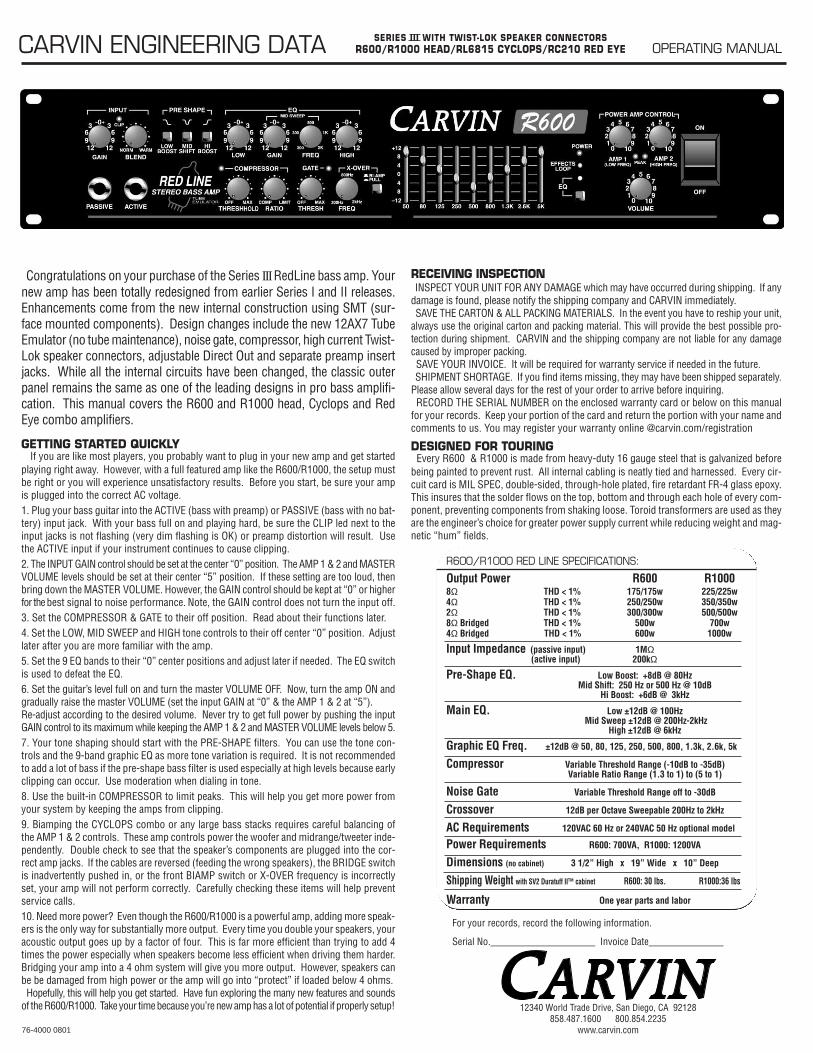
HELPFUL HINTS1) POOR BIAMP SOUND: The speaker cables from AMP 1 (woofers) and AMP 2 (tweet-
ers) have been reversed, AMP 1 and 2 level controls are not balanced or the X-OVER has been set at an incorrect frequency. (start at 800 Hz).
2) NO SOUND FROM AMPS 1 & 2: The rear BRIDGE switch has been inadvertently pushed inor speakers plugged into wrong jacks.
3) NO HIGH FREQUENCIES: Tweeters or midrange drivers have been damaged from to much power.
4) WEAK BASS: The speaker systems are wired out of phase to each other. To correct, reverse the wires on one speaker connectors.
5) DIR XLR HUM: Try switching the rear GND LIFT switch IN or OUT. If the hum is not elim-inated, use a 600Ω line input transformer cutting the input ground on the connectors (Pin 3).
1 2 3 4 5 6 7 8 9
Twist-Lok cables are recommended for your bass rig because of their high cur-rent capacity. While the standard 16 GA 1/4” cables will work OK with your system,the CARVIN 12 GA Twist-Lok cables will allow you to gain as much as 20% morepower at high power levels extracting every watt from your RedLine bass amp.The very short 1/4” cables will work for the RC210 and RL6815 combo amps.
FULL RANGE MODE:The FULL RANGE mode of your RedLine bass amp works well with separate bassand full-range speaker systems. Instead of using the Bi-Amp mode, you can simplyrun AMP 1 into your bass speakers and AMP 2 into your full-range speakers usingthe natural crossover frequencies of each speaker system. If you need deeperbass or more highs, just turn up amp 1 or amp 2 for a balance sound. The frontpanel X-OVER switch must be pushed “IN” for the FULL-RANGE MODE.
FRONT PANEL CONTROLS
SPEAKER CONNECTIONS
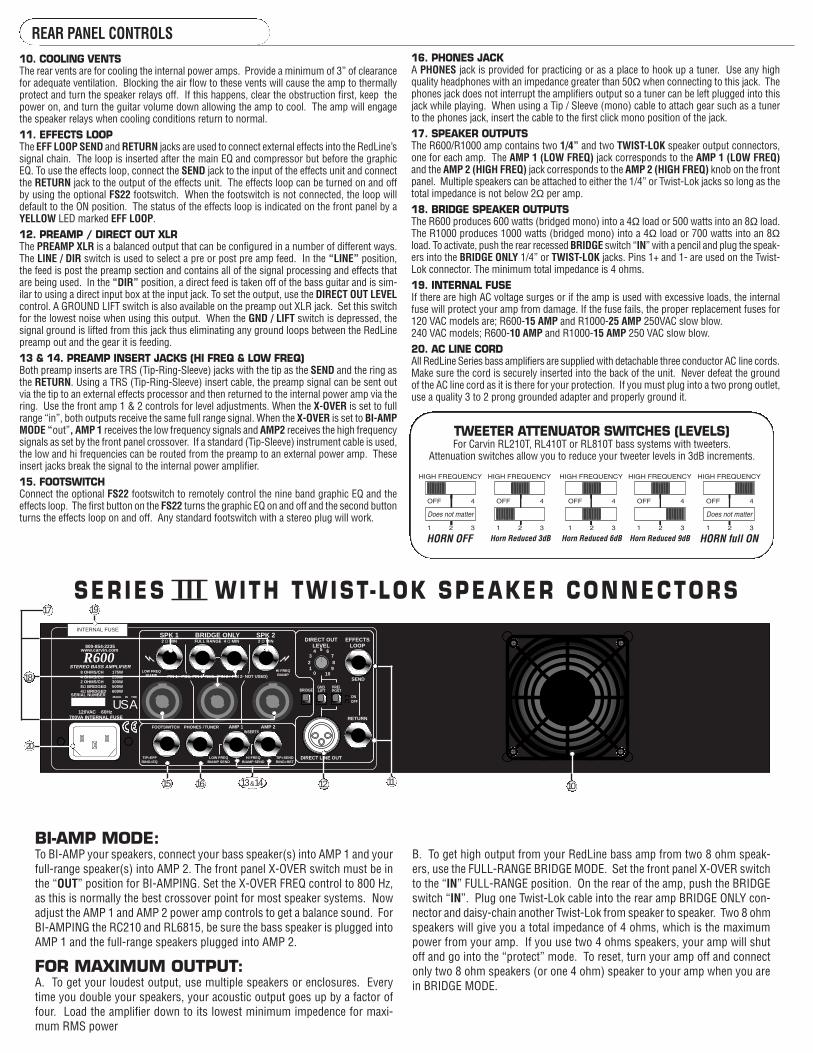
BI-AMP MODE:To BI-AMP your speakers, connect your bass speaker(s) into AMP 1 and yourfull-range speaker(s) into AMP 2. The front panel X-OVER switch must be inthe “OUT” position for BI-AMPING. Set the X-OVER FREQ control to 800 Hz,as this is normally the best crossover point for most speaker systems. Nowadjust the AMP 1 and AMP 2 power amp controls to get a balance sound. ForBI-AMPING the RC210 and RL6815, be sure the bass speaker is plugged intoAMP 1 and the full-range speakers plugged into AMP 2.
FOR MAXIMUM OUTPUT:A. To get your loudest output, use multiple speakers or enclosures. Everytime you double your speakers, your acoustic output goes up by a factor offour. Load the amplifier down to its lowest minimum impedence for maxi-mum RMS power
BI-AMP MODE:B. To get high output from your RedLine bass amp from two 8 ohm speak-ers, use the FULL-RANGE BRIDGE MODE. Set the front panel X-OVER switchto the “IN” FULL-RANGE position. On the rear of the amp, push the BRIDGE switch “IN”. Plug one Twist-Lok cable into the rear amp BRIDGE ONLY con-nector and daisy-chain another Twist-Lok from speaker to speaker. Two 8 ohmspeakers will give you a total impedance of 4 ohms, which is the maximumpower from your amp. If you use two 4 ohms speakers, your amp will shutoff and go into the “protect” mode. To reset, turn your amp off and connectonly two 8 ohm speakers (or one 4 ohm) speaker to your amp when you arein BRIDGE MODE.
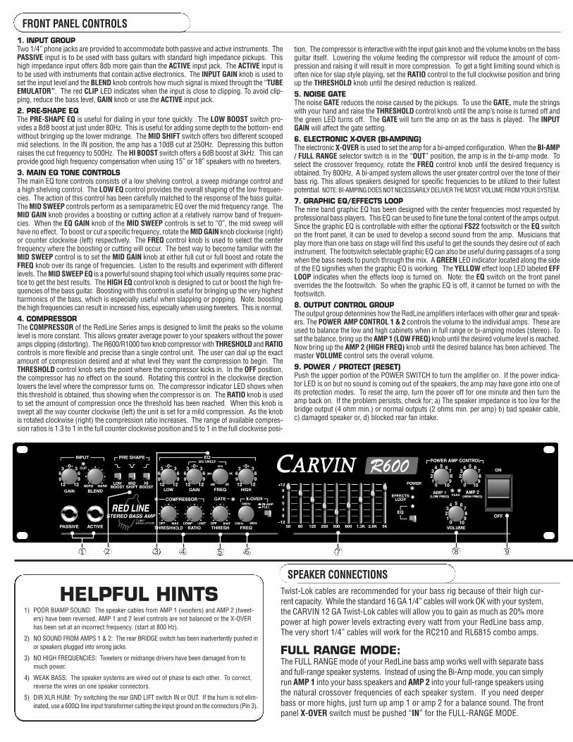
10. COOLING VENTSThe rear vents are for cooling the internal power amps. Provide a minimum of 3” of clearancefor adequate ventilation. Blocking the air flow to these vents will cause the amp to thermallyprotect and turn the speaker relays off. If this happens, clear the obstruction first, keep thepower on, and turn the guitar volume down allowing the amp to cool. The amp will engagethe speaker relays when cooling conditions return to normal.11. EFFECTS LOOPThe EFF LOOP SEND and RETURN jacks are used to connect external effects into the RedLine’ssignal chain. The loop is inserted after the main EQ and compressor but before the graphicEQ. To use the effects loop, connect the SEND jack to the input of the effects unit and connectthe RETURN jack to the output of the effects unit. The effects loop can be turned on and offby using the optional FS22 footswitch. When the footswitch is not connected, the loop willdefault to the ON position. The status of the effects loop is indicated on the front panel by aYELLOW LED marked EFF LOOP.12. PREAMP / DIRECT OUT XLRThe PREAMP XLR is a balanced output that can be configured in a number of different ways.The LINE / DIR switch is used to select a pre or post pre amp feed. In the “LINE” position,the feed is post the preamp section and contains all of the signal processing and effects thatare being used. In the “DIR” position, a direct feed is taken off of the bass guitar and is sim-ilar to using a direct input box at the input jack. To set the output, use the DIRECT OUT LEVELcontrol. A GROUND LIFT switch is also available on the preamp out XLR jack. Set this switchfor the lowest noise when using this output. When the GND / LIFT switch is depressed, thesignal ground is lifted from this jack thus eliminating any ground loops between the RedLinepreamp out and the gear it is feeding.13 & 14. PREAMP INSERT JACKS (HI FREQ & LOW FREQ)Both preamp inserts are TRS (Tip-Ring-Sleeve) jacks with the tip as the SEND and the ring asthe RETURN. Using a TRS (Tip-Ring-Sleeve) insert cable, the preamp signal can be sent outvia the tip to an external effects processor and then returned to the internal power amp via thering. Use the front amp 1 & 2 controls for level adjustments. When the X-OVER is set to fullrange “in”, both outputs receive the same full range signal. When the X-OVER is set to BI-AMPMODE “out”, AMP 1 receives the low frequency signals and AMP2 receives the high frequencysignals as set by the front panel crossover. If a standard (Tip-Sleeve) instrument cable is used,the low and hi frequencies can be routed from the preamp to an external power amp. Theseinsert jacks break the signal to the internal power amplifier.15. FOOTSWITCHConnect the optional FS22 footswitch to remotely control the nine band graphic EQ and theeffects loop. The first button on the FS22 turns the graphic EQ on and off and the second buttonturns the effects loop on and off. Any standard footswitch with a stereo plug will work.
R600
SPK 1 SPK 2
SEND
RETURN
PRE/GND
FOOTSWITCH
800-854-2235
STEREO BASS AMPLIFIER
www.carvin.com
MADE
AUSIN THESERIAL NUMBER
8 OHMS/CH4 OHMS/CH2 OHMS/CH8Ω BRIDGED4Ω BRIDGED
175W250W300W500W600W
BRIDGE ONLY
HI FREQBIAMP
LOW FREQBIAMP
FULL RANGE 4 Ω MIN
AMP 2AMP 1INSERTS
TIP±SENDRING±RET
DIRECT LINE OUT
BRIDGE POSTLIFT
EFFECTSLOOP
PIN 1+ POS, PIN 1- NEG, (PIN 2+ PIN 2- NOT USED)
2 Ω MIN
PHONES / TUNER
2 Ω MIN
TIP±EFFRING±EQ
DIRECT OUTLEVEL
0 101 9
87
65432
120VAC 60Hz 700VA INTERNAL FUSE
HI FREQBIAMP SEND
LOW FREQBIAMP SEND
OFFON
16. PHONES JACKA PHONES jack is provided for practicing or as a place to hook up a tuner. Use any highquality headphones with an impedance greater than 50Ω when connecting to this jack. Thephones jack does not interrupt the amplifiers output so a tuner can be left plugged into thisjack while playing. When using a Tip / Sleeve (mono) cable to attach gear such as a tunerto the phones jack, insert the cable to the first click mono position of the jack.17. SPEAKER OUTPUTSThe R600/R1000 amp contains two 1/4” and two TWIST-LOK speaker output connectors,one for each amp. The AMP 1 (LOW FREQ) jack corresponds to the AMP 1 (LOW FREQ)and the AMP 2 (HIGH FREQ) jack corresponds to the AMP 2 (HIGH FREQ) knob on the frontpanel. Multiple speakers can be attached to either the 1/4” or Twist-Lok jacks so long as thetotal impedance is not below 2Ω per amp. 18. BRIDGE SPEAKER OUTPUTSThe R600 produces 600 watts (bridged mono) into a 4Ω load or 500 watts into an 8Ω load.The R1000 produces 1000 watts (bridged mono) into a 4Ω load or 700 watts into an 8Ωload. To activate, push the rear recessed BRIDGE switch “IN” with a pencil and plug the speak-ers into the BRIDGE ONLY 1/4” or TWIST-LOK jacks. Pins 1+ and 1- are used on the Twist-Lok connector. The minimum total impedance is 4 ohms.19. INTERNAL FUSEIf there are high AC voltage surges or if the amp is used with excessive loads, the internalfuse will protect your amp from damage. If the fuse fails, the proper replacement fuses for120 VAC models are; R600-15 AMP and R1000-25 AMP 250VAC slow blow. 240 VAC models; R600-10 AMP and R1000-15 AMP 250 VAC slow blow.20. AC LINE CORDAll RedLine Series bass amplifiers are supplied with detachable three conductor AC line cords.Make sure the cord is securely inserted into the back of the unit. Never defeat the groundof the AC line cord as it is there for your protection. If you must plug into a two prong outlet,use a quality 3 to 2 prong grounded adapter and properly ground it.
15 13 &14
20
12 11
19
INTERNAL FUSE
10
17
18
SER IES I I I W ITH TWIST- LOK SPEAKER CONNECTORS
16
TWEETER ATTENUATOR SWITCHES (LEVELS)For Carvin RL210T, RL410T or RL810T bass systems with tweeters.
Attenuation switches allow you to reduce your tweeter levels in 3dB increments.
REAR PANEL CONTROLS
HORN OFF HORN full ONHorn Reduced 3dB Horn Reduced 6dB Horn Reduced 9dB
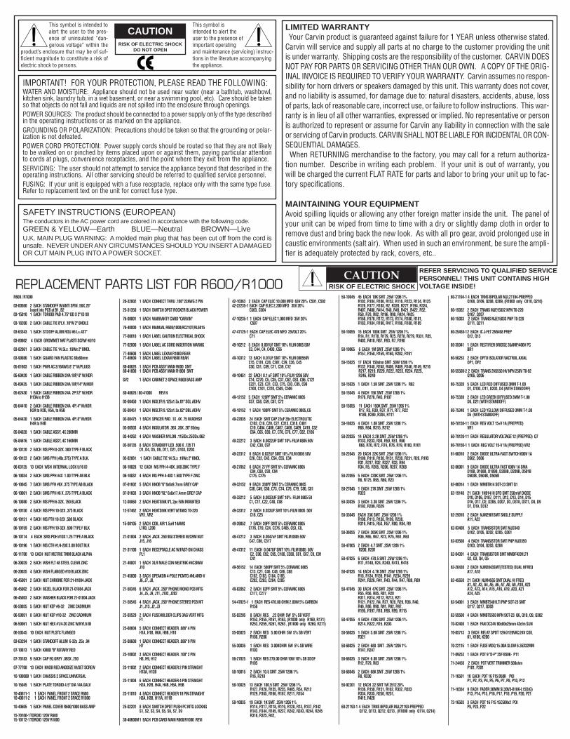
CAUTIONRISK OF ELECTRIC SHOCK
DO NOT OPEN
SAFETY INSTRUCTIONS (EUROPEAN)The conductors in the AC power cord are colored in accordance with the following code.GREEN & YELLOW—Earth BLUE—Neutral BROWN—LiveU.K. MAIN PLUG WARNING: A molded main plug that has been cut off from the cord isunsafe. NEVER UNDER ANY CIRCUMSTANCES SHOULD YOU INSERT A DAMAGEDOR CUT MAIN PLUG INTO A POWER SOCKET.
IMPORTANT! FOR YOUR PROTECTION, PLEASE READ THE FOLLOWING:WATER AND MOISTURE: Appliance should not be used near water (near a bathtub, washbowl,kitchen sink, laundry tub, in a wet basement, or near a swimming pool, etc). Care should be takenso that objects do not fall and liquids are not spilled into the enclosure through openings.POWER SOURCES: The product should be connected to a power supply only of the type describedin the operating instructions or as marked on the appliance.GROUNDING OR POLARIZATION: Precautions should be taken so that the grounding or polar-ization is not defeated.POWER CORD PROTECTION: Power supply cords should be routed so that they are not likelyto be walked on or pinched by items placed upon or against them, paying particular attentionto cords at plugs, convenience receptacles, and the point where they exit from the appliance.SERVICING: The user should not attempt to service the appliance beyond that described in theoperating instructions. All other servicing should be referred to qualified service personnel.FUSING: If your unit is equipped with a fuse receptacle, replace only with the same type fuse.Refer to replacement text on the unit for correct fuse type.
REFER SERVICING TO QUALIFIED SERVICEPERSONNEL! THIS UNIT CONTAINS HIGHVOLTAGE INSIDE!
CAUTIONRISK OF ELECTRIC SHOCKREPLACEMENT PARTS LIST FOR R600/R1000
This symbol is intended toalert the user to the pres-ence of uninsulated “dan-gerous voltage” within the
product’s enclosure that may be of suf-ficient magnitude to constitute a risk ofelectric shock to persons.
This symbol isintended to alert theuser to the presence ofimportant operatingand maintenance (servicing) instruc-tions in the literature accompanyingthe appliance.
LIMITED WARRANTYYour Carvin product is guaranteed against failure for 1 YEAR unless otherwise stated.
Carvin will service and supply all parts at no charge to the customer providing the unitis under warranty. Shipping costs are the responsibility of the customer. CARVIN DOESNOT PAY FOR PARTS OR SERVICING OTHER THAN OUR OWN. A COPY OF THE ORIG-INAL INVOICE IS REQUIRED TO VERIFY YOUR WARRANTY. Carvin assumes no respon-sibility for horn drivers or speakers damaged by this unit. This warranty does not cover,and no liability is assumed, for damage due to: natural disasters, accidents, abuse, lossof parts, lack of reasonable care, incorrect use, or failure to follow instructions. This war-ranty is in lieu of all other warranties, expressed or implied. No representative or personis authorized to represent or assume for Carvin any liability in connection with the saleor servicing of Carvin products. CARVIN SHALL NOT BE LIABLE FOR INCIDENTAL OR CON-SEQUENTIAL DAMAGES.
When RETURNING merchandise to the factory, you may call for a return authoriza-tion number. Describe in writing each problem. If your unit is out of warranty, youwill be charged the current FLAT RATE for parts and labor to bring your unit up to fac-tory specifications.
MAINTAINING YOUR EQUIPMENTAvoid spilling liquids or allowing any other foreign matter inside the unit. The panel ofyour unit can be wiped from time to time with a dry or slightly damp cloth in order toremove dust and bring back the new look. As with all pro gear, avoid prolonged use incaustic environments (salt air). When used in such an environment, be sure the ampli-fier is adequately protected by rack, covers, etc..
R600 / R1000
03-00560 2 EACH STANDOFF W/ANTI SPIN .56X.25" insert into PCB at B1, B2
03-15010 1 EACH TOROID PAD 4.75" OD X 2" ID X0
03-18200 2 EACH CABLE TIE 8"LX .10"W 2" BNDLE
03-63343 1 EACH STDOFF ALUM ROU #6 L=.437"
03-80602 4 EACH GROMMET NAT PLASTI SCRW #8/10
03-82061 3 EACH CABLE TIE 14.5Lx .19Wx 2" BNDL
03-90080 1 EACH GUARD FAN PLASTIC 80x80mm
05-01603 1 EACH PWR AC 3/16AWG 8' 2" W/PLUGS
05-60420 1 EACH CABLE RIBBON 24A 10P/ 8" W/HDR
05-60435 1 EACH CABLE RIBBON 24A 10P/14" W/HDR
05-62430 1 EACH CABLE RIBBON 24A 2P/12" W/HDR H13A to H13B
05-64410 2 EACH CABLE RIBBON 24A 4P/ 4" W/HDR H2A to H2B, H5A, to H5B
05-64420 1 EACH CABLE RIBBON 24A 4P/ 8" W/HDR H4A to H4B
05-84628 1 EACH CABLE ASSY, 4C 280MM
05-84616 1 EACH CABLE ASSY, 4C 160MM
06-10120 2 EACH MS PPH 8-32X .500 TYPE F BLACK
06-10133 2 EACH SMS PPH (#8x.375) TYPE A BLK.
06-03125 13 EACH WSH INTERNAL LOCK 5/16 ID
06-10034 2 EACH SMS PPH #4X 1.00 TYPE AB BLK
06-10045 7 EACH SMS PFH #6X .375 TYPE AB BLACK
06-10061 2 EACH SMS PPH #6 X .375 TYPE A BLACK
06-10080 2 EACH MS PPH 6-32X .750 BLACK
06-10150 4 EACH MS PPH 10-32X .375 BLACK
06-10151 4 EACH MS PTH 10-32X .500 BLACK
06-10159 2 EACH MS PPH 10-32X .500 TYPE F BLK
06-10174 4 EACH SMS POH #10X 1.25 TYPE A BLACK
06-10196 1 EACH MS CTH #1/4-20X 3.00 BOLT BLK
06-11700 13 EACH NUT METRIC 7MM BLACK ALPHA
06-30029 2 EACH WSH FLT #8 STEEL CLEAR ZINC
06-30035 4 EACH WSH FLANGED #10 BLACK ZINC
06-45001 2 EACH NUT CHROME FOR 21-01804 JACK
06-45002 2 EACH BEZEL BLACK FOR 21-01804 JACK
06-45003 2 EACH WASHER BLACK FOR 21-01804 JACK
06-50035 5 EACH NUT KEP #6-32 ZINC CADMIUM
06-50051 8 EACH NUT KEP #10-32 ZINC CADMIUM
06-50061 1 EACH NUT HEX #1/4-20 ZINC W/NYLN IN
06-50545 10 EACH NUT PLSTC FLANGED
03-63294 1 EACH STANDOFF ALUM 6-32x .25x .94
07-10813 1 EACH KNOB "8" ROTARY RED
07-70183 9 EACH CAP EQ GREY .093X .250
07-77708 13 EACH KNOB RED ANODIZE W/SET SCREW
10-10008B 1 EACH CHASSIS 2 SPACE UNIVERSAL
10-15045 1 EACH PLATE TOROID 4.5" DIA 14A GALV
10-40611-1 1 EACH PANEL FRONT 2 SPACE R600 10-40611-2 1 EACH PANEL FRONT 2 SPACE R1000
10-40605 1 EACH PANEL COVER R600/1000 BASS AMP
15-70160-1TOROID 120V R60015-10172-1TOROID 120V R1000
20-32002 1 EACH CONNECT THRU .100" 22AWG 2 PIN
25-31350 1 EACH SWITCH DPST ROCKER BLACK POWER
76-00001 1 EACH WARRANTY CARD "CARVIN"
76-40000 1 EACH MANUAL R600/1000/RC210T/RL6815
77-00010 1 EACH LABEL CAUTION ELECTRICAL SHOCK
77-02800 1 EACH LABEL AC CORD INSERTION WARNG
77-40608 1 EACH LABEL LEXAN R1000 REAR 77-40609 1 EACH LABEL LEXAN R600 REAR
80-40626 1 EACH PCB ASSY MAIN R600 SMT 80-41000 1 EACH PCB ASSY MAIN R1000 SMT
SV2 1 EACH CABINET 2-SPACE R600 BASS AMP
80-40626 / 80-41000 REV N
03-00450 1 EACH INSLTR 9.125x1.5x.01" SGL ADHV
03-00451 1 EACH INSLTR 9.125x1.5x.02" DBL ADHV
03-00475 1 EACH SPACER PAD .1X .4X .75 W/ADHSV
03-00503 4 EACH INSULATOR .36X .36X .20" 85deg
03-44262 4 EACH WASHER NYLON .115IDx.25ODx.062
03-50135 8 EACH STANDOFF LED .500 X .135 T1 D1, D4, D5, D6, D11, D21, D103, D203
03-82061 1 EACH CABLE TIE 14.5Lx .19Wx 2" BNDL
06-10028 12 EACH MS PPH 4-40X .500 ZINC TYPE F
06-10032 4 EACH MS PPH 4-40X 1.500 TYPE F ZINC
07-01602 5 EACH KNOB "6" 6x6x9.7mm GREY CAP
07-01603 3 EACH KNOB "6L" 6x6x17.4mm GREY CAP
12-00860 2 EACH HEATSINK 9"L 2pc FAN MOUNTED
12-57462 2 EACH HEATSINK VERT W/TABS T0-220 VR1, VR2
15-00105 2 EACH COIL AIR 1.5uH 14AWG L100, L200
21-01804 2 EACH JACK .250 90d STEREO W/CRM NUT J15, J16
21-31100 1 EACH RECEPTACLE AC W/FAST-ON CHASS PL1
21-40001 1 EACH XLR MALE CON NEUTRIK #NC3MAV J10
21-45000 3 EACH SPEAKON 4-POLE PCMTG #NL4MD-V J6, J7, J8,
21-50345 6 EACH JACK .250" PHONE MONO PCB MTG J4, J5, J9, J11, J102, J202
21-50545 4 EACH JACK .250" PHONE STEREO PCB MT J1, J13, J2, J3
23-03529 2 EACH FUSEHOLDER CLIPS 3AG VERT MTG F1
23-08604 5 EACH CONNECT HEADER .086" 4 PIN H1A, H1B, H6A, H6B, H10
23-08609 1 EACH CONNECT HEADER .086" 9 PIN H7
23-10002 3 EACH CONNECT HEADER .100" 2 PIN H8, H9, H12
23-11002 2 EACH CONNECT HEADER 2 PIN STRAIGHT H13A, H13B
23-11004 6 EACH CONNECT HEADER 4 PIN STRAIGHT H2A, H2B, H4A, H4B, H5A, H5B
23-11010 4 EACH CONNECT HEADER 10 PIN STRAIGHT H3A, H3B, H11A, H11B
25-02201 8 EACH SWITCH DPDT PUSH PC MTG LOCKNG S1, S2, S3, S4, S5, S6, S7, S9
30-40600M1 EACH PCB CARD MAIN R600/R1000 REVI
42-10363 2 EACH CAP ELEC 10,000 MFD 63V 20% C501, C502 42-22235-1 EACH CAP ELEC 2,200 MFD 35V 20%
C503, C504
47-10235-1 1 EACH CAP ELEC 1,000 MFD 35V 20% C507
47-47125-1 EACH CAP ELEC 470 MFD 25VOLT 20% C71
49-10212 5 EACH 0.001UF SMT 10% FILM 0805 50V C3, C44, C4, C403, C56
49-10312 13 EACH 0.01UF SMT 10% FILM 080550V C15, C181, C28, C281, C29, C36, C45 C50, C51, C89, C11, C39, C12
49-10451 22 EACH 0.1 uF SMT 10% FILM 1206 50V C14, C270, C5, C35, C37, C62, C63, C96, C121 C221, C23, C31, C33, C75, C83, C85, C99 C100, C101, C310, C505, C506
49-12152 5 EACH 120PF SMT 5% CERAMIC 0805 C57, C58, C59, C67, C72
49-18152 1 EACH 180PF SMT 5% CERAMIC 0805,C6
49-22035 24 EACH SMT CAP 22uF 35v ELECTROLITIC C102, C18, C20, C27, C313, C318, C401 C10, C404, C406, C407, C408, C409, C410, C52 C64, C65, C69, C7, C70, C76, C77, C82, C186
49-22212 3 EACH 0.0022UF SMT 10% FILM 0805 50V C42, C38, C97
49-22312 6 EACH 0.022UF SMT 10% FILM 0805 50V C26, C32, C43, C54, C55, C34
49-27052 6 EACH 27 PF SMT 5% CERAMIC 0805 C84, C88, C93, C94 C175, C275
49-33152 9 EACH 330PF SMT 5% CERAMIC 0805 C30, C49, C60, C73, C74, C78, C79, C80, C81
49-33212 5 EACH 0.0033UF SMT 10% FILM 0805 50 C1, C17, C22, C40, C98
49-33312 2 EACH 0.033UF SMT 10% FILM 0805 50V C16, C25
49-39052 7 EACH 39PF SMT 5% CERAMIC 0805 C176, C19, C24, C276, C405, C53, C8,
49-47212 3 EACH 0.0047uF SMT FILM 0805 50V C47, C86, C317
49-47312 11 EACH 0.047UF SMT 10% FILM 0805 50V C2, C90, C92, C95, C180, C280, C61, C87, C9, C91 C41
49-56152 14 EACH 560PF SMT 5% CERAMIC 0805 C13, C21, C46, C48, C66, C68 C182, C183, C184, C185, C282, C283, C284, C285
49-82052 2 EACH 82PF SMT 5% CERAMIC 0805 C177, C277
54-47025-1 1 EACH RES 470.00 OHM 2.00W 5% CARBON R156
55-02205 8 EACH RES .22 OHM 5W 5% SB VERT R153, R155, R161, R163, (R1000 only R169, R171) R253, R255, R261, R263 , (R1000 only R269, R271)
55-05025 2 EACH RES 5.00 OHM 5W 5% SB VERT R186, R286
55-30035 1 EACH RES 3.00KOHM 5W 5% SB WIRE R103
56-27025 1 EACH RES 270.00 OHM 10W 10% SB SDOF R105
58-10015 2 EACH 10.5 SMT .25W 1206 1% R16, R210
58-10025 13 EACH 100.5 SMT .25W 1206 1% R127, R128, R135, R235, R405, R54, R212 R129, R165, R166, R167, R211, R154
58-10035 19 EACH 1K SMT .25W 1206 1% R114, R117, R118, R119, R120, R13, R137, R142 R143, R144, R145, R237, R242, R243, R244, R245 R318, R325, R42,
58-10045 45 EACH 10K SMT .25W 1206 1% R102, R104, R106, R152, R116, R123, R124, R125 R126, R177, R188, R2, R320, R277, R194, R324, R407, R408, R414, R48, R49, R421, R422, R52, R58, R78, R82, R196, R98, R424, R425 R168, R170, R172, R173, R174, R180, R181, R183, R184, R190, R417, R198, R188, R185
58-10055 15 EACH 100K SMT .25W 1206 1% R14, R1, R178, R179, R25, R278, R279, R331, R35, R402, R410, R87, R93, R7, R198
58-10065 6 EACH 1M SMT .25W 1206 1% R157, R158, R159, R160, R202, R191
58-15025 17 EACH 150ohm SMT .50W 1206 1% R132, R148, R248, R406, R409, R146, R149, R216 R217, R219, R220, R222, R223, R224, R225, R246, R249
58-15035 1 EACH 1.5K SMT .25W 1206 1% R62
58-15045 4 EACH 15K SMT .25W 1206 1% R176, R276, R45, R107
58-15055 11 EACH 150K SMT .25W 1206 1% R17, R3, R30, R37, R71, R77, R22 R189, R289, R204, R111
58-18035 4 EACH 1.8K SMT .25W 1206 1% R66, R64, R315, R312
58-22035 14 EACH 2.2K SMT .25W 1206 1% R133, R233, R39, R50, R51, R60 R68, R70, R72, R74, R76, R19, R100, R101
58-22045 20 EACH 22K SMT .25W 1206 1% R109, R110, R130, R131, R230, R231, R26, R193 R31, R317, R32, R327, R33, R94 R34, R5, R205, R206, R207, R208
58-22055 5 EACH 220K SMT .25W 1206 1% R6, R175, R95, R69, R23
58-27045 1 EACH 27K SMT .25W 1206 1% R323
58-33035 3 EACH 3.3K SMT .25W 1206 1% R192, R209, R329
58-33045 EACH 33K SMT .25W 1206 1% R108, R113, R138, R199, R238, R319, R415, R53, R57, R80, R84, R9
58-36055 7 EACH 365K SMT .25W 1206 1% R36, R65, R67, R73, R75, R61, R63
58-47005 2 EACH 4.7 SMT .25W 1206 1% R200, R201
58-47025 6 EACH 470.5 SMT .25W 1206 1% R11, R140, R24, R240, R413, R418
58-47035 14 EACH 4.7K SMT .25W 1206 1% R18, R134, R139, R141, R234, R239 R241, R326, R41, R43, R44, R47, R88, R89
58-47045 30 EACH 47K SMT .25W 1206 1% R55, R56, R85, R81, R20 R311, R314, R112, R213, R21 R121, R122, R4, R27, R28, R29, R38, R40, R46, R86, R90, R91, R92, R97, R195, R197, R10, R96, R99, R115
58-47055 4 EACH 470K SMT .25W 1206 1% R214, R322, R15, R203
58-56035 1 EACH 5.6K SMT .25W 1206 1% R321
58-68025 2 EACH 680 SMT .25W 1206 1% R147, R247
58-68035 3 EACH 6.8K SMT .25W 1206 1% R12, R79, R83
58-68045 2 EACH 68K SMT .25W 1206 1% R8, R330
58-92201 12 EACH 22 SMT 1W 2512 20% R136, R150, R151, R182, R332, R333 R334, R335, R250, R251, R419, R420
60-21193-1 4 EACH TRNS BIPOLAR MJL21193-PREPPED Q112, Q113, Q212, Q213 , (R1000 only Q114, Q214)
60-21194-1 4 EACH TRNS BIPOLAR MJL21194-PREPPED Q108, Q109, Q208, Q209, (R1000 only Q110, Q210)
60-15032 2 EACH TRANS MJE15032 NPN T0-220 Q107, Q207
60-15033 2 EACH TRANS MJE15033 PNP T0-220 Q111, Q211
60-25458-12 EACH IC J-FET 2N5458 PREP Q12, Q13
60-35041 1 EACH RECTIFIER BRIDGE 35AMP/400V PCBR1
60-50253 2 EACH OPTO ISOLATOR VACTROL AXIAL OP1, OP2
60-55500-2 2 EACH TRANS 2N5550 HV NPN 250V T0-92 Q106, Q206
60-75320 5 EACH LED RED DIFFUSED 3MM T-1.00 D1, D103, D11, D203, D4 (WITH STANDOFF)
60-75330 2 EACH LED GREEN DIFFUSED 3MM T-1.00 D6, D21 (WITH STANDOFF)
60-75340 1 EACH LED YELLOW DIFFUSED 3MM T-1.00 D5 (WITH STANDOFF)
60-78150-11 EACH REG VOLT 15+V 1A (PREPPED) VR1
60-79120-11 EACH REGULATOR VOLTAGE 12 (PREPPED) Q7
60-79150-1 1 EACH REG VOLT 15-V 1A (PREPPED) VR2
61-60010 2 EACH DIODE ULTRA-FAST SWTCH 600V 1A D502, D506
62-06001 9 EACH DIODE ULTRA FAST 600V 1A SMA D18B, D108B, D109B, D208B, D209B, D501B D503B, D504B, D505B
62-00014 1 EACH MMBTA14 SOT-23 SMT Q1
62-19140 21 EACH 1N914 HI SPD SMT 250mW DIODE D10, D106, D107, D111, D12, D13, D14, D15 D16, D17, D2, D206, D207, D3, D310, D311, D8, D9 D7, D19, D312
62-29010 2 EACH NJM2901SMT SNGLE SUPPLY A11, A22
62-03400 5 EACH TRANSISTOR SMT MJD340 Q102, Q105, Q202, Q205, Q301
62-03500 4 EACH TRANSISTOR SMT PNP MJD350 Q103, Q104, Q203, Q204
62-04391 4 EACH TRANSISTOR SMT MMBF4391LT1 Q2, Q3, Q4, Q5
62-20430 2 EACH NJM2043SMT(TESTED) DUAL HFREQ A17, A18
62-45650 21 EACH NJM4565 SMT DUAL HI FREQ A1, A2, A3, A4, A5, A6, A7, A8, A9, A10, A23 A12, A13, A14, A15, A16, A19, A20, A21 A24, A25
62-54001 3 EACH MMBT5401LTI PNP SOT-23 SMT Q117, Q217, Q303
62-55500 4 EACH MMBT5550 NPN SOT-23 Q6, Q10, Q9, Q302
70-02408 1 EACH FAN DC24V 80x80x25mm 42cfm SUN
70-05713 3 EACH RELAY SPDT 12A@120VAC/24V COIL K1, K100, K200
70-22115 1 EACH FUSE MDQ 15.00A SLOW 6.35X32MM
71-09253 1 EACH POT 9 "D-P" 25F B50K- P11
71-24450 2 EACH POT VERT TRIMMER 500ohm P101, P201
71-16501 10 EACH POT 16 F15 B50K POI P1, P2, P3, P4, P5, P6, P7, P8, P10, P12
71-10334 9 EACH FADER 30MM SL30V3-B10K-L15D(G) P13, P14, P15, P16, P17, P18, P19, P20, P21
72-16503 3 EACH POT 16 F15 15C50Kx2 POI P9, P23, P22