CARVIN ENGINEERING DATA NOMAD, BEL AIR …carvinimages.com/manuals/belair.pdf · Guitar Player...
4
VINTAGE16 SPECS: RMS Power: 16/5 watts Output Imp: 8Ω Input Imp: 100,000 ohms Tone Controls: BASS: 80Hz MID: 600-700Hz TREBLE: 11k Hz Sensitivity: 1mV for clipping 16mV for full output Preamp Tubes: 3—12AX7’s (dual stage) Power Tubes: 2—EL84’s USA Model: 120VAC, 300VA USA Fuse: 1A 250V slow blow, 5 x 20mm Export Model: 240VAC Export Fuse: 1A 250V slow blow, 5 x 20mm Cabinet Size: 16W x 17.75H x 8.5”D, 31 lbs. Cabinet: 7-ply poplar wood Warranty: One Year Options: CV16 cover CARVIN ENGINEERING DATA OPERATING MANUAL NOMAD & BEL AIR COMBO SPECS: Speakers: One/Two Celestion G12 Vintage 30 12” spks RMS Power: 33 watts Vintage 33, 50 watts all others Output Imp: 4, 8 & 16Ω Input Imp: 100,000 ohms Tone Controls: BASS: 80Hz Both Channels: MID: 600-700Hz TREBLE: 11k Hz Ch 1 Sensitivity: 1mV for clipping Ch 2 Sensitivity: 16mV for full output Channels: 2—switching Voiced Line Out: 1.5 VAC @ 100 watts RMS Preamp Tubes: 5—12AX7’s (dual stage) Power Tubes: 4—EL84’s USA Model: 120VAC, 300VA USA Fuse: 3A 250V slow blow, 5 x 20mm Export Model: 230VAC, 300VA Export Fuse: 1.5A 250V slow blow, 5 x 20mm 112 Cabinet : 19.5W x 10.25D x 17.5”H, 44 lbs. 212 Cabinet : 26W x 10.25D x 17.75”H, 56 lbs. Cabinet: 7-ply poplar wood Warranty: One Year Options: CV3212 cover, FS22 footswitch 76-10302C 0705 12340 World Trade Drive, San Diego, CA 92128 800.854.2235 carvin.com For your records, you may wish to record the following information. Serial No._____________________ Invoice Date_______________ 212 Bel Air™ NOMAD, BEL AIR COMBO & VINTAGE16 GUITAR AMPS Congratulations on your purchase of the VINTAGE TUBE SERIES all tube ampli- fier. Carvin has been building tube guitar amplifiers since 1949. They have been used by top professionals like; Joe Walsh, Chet Atkins, Jeff Beck, James Burton, Jorma Kaukonen, and many other great musicians. You will discover that these amplifiers represent a significant sound improvement over conventional tube ampli- fiers. Spend time with your new amp and get to know it’s many sounds. TECHNICAL DESIGN OF THE VINTAGE TUBE SERIES The VINTAGE TUBE SERIES is 100% tube design—no IC’s, FET’s or transistors. The design criteria was to build an all-tube guitar amp that sounded better than anything else on the market. This meant that the VINTAGE TUBE SERIES was going to be totally new from the ground up and that it was going to be an all tube design. DYNAMIC EL84 POWER TUBES Premium EL84 power tubes are selected for their excellent saturation and power soak char- acteristics. Just like early VOX AC30 amps, EL84’s are used for their ideal transconduc- tance delivering a tight bottom and soft drive with superior definition. HIGH IMPEDANCE GUITAR INPUT Carvin has long known about the effects of miss-loading a guitar pickup which can cause high frequency loss. The VINTAGE TUBE SERIES guards against this loss with its ultra high input impedance. Also, we considered the capacitance of the average shielded guitar cable which can reduce the high frequency response of your guitar pickups. Unlike other ampli- fiers, we purposely avoided adding capacitance anywhere in the preamp to control high fre- quency oscillations. Instead, we controlled oscillations through careful component layout and lead placement allowing its shimmering highs to be reproduced. CLEAN AND SOAK CHANNELS The equalization of the clean and soak channel is designed to offer clarity to your instru- ment. Special mud-cutting circuits eliminate the unwanted sounds in the 500 to 700 Hz range which normally take away the tone definition of your instrument. You will also take notice of the clean channels rear PRESENCE control which adds acoustic voicing to your instrument. This control boosts only the guitars very highest harmonics which are in the 10k Hz range instead of the normal 3K Hz of a bright switch. TONE CONTROLS The T-Bridge passive BASS, MID and TREBLE tone controls offer a wide range of tone set- tings. Take full advantage by setting them where they sound best. Your sound may not be at center (5 on the dial). Instead, the treble and bass may need to be at 10 while the mid con- trol at 0 (or) the treble at 1 and the bass at 10 depending dual or single coil pickups. These controls will not affect or color your sound when set at extreme settings, nor do they interact with each other. The greater range of these controls comes from the high impedance 1 meg sealed pots (most guitar amps use 250k pots). The frequency of the bass control is set at 80 Hz while the mid control is set at 650 Hz. The treble control is set at a very high 11k Hz giving the VINTAGE TUBE SERIES it’s dynamic highs. REVERB The FS22 footswith for the long tailed REVERB system in the VINTAGE TUBE SERIES switches only the reverb “send” leaving the tail of the reverb to decay naturally, the way it’s done in the studio. A special pre filter eliminates the spring “boing” normally heard in other sys- tems giving it a “lush” sound. The all tube reverb system offers vibrant clarity with full depth reminiscent of the sixties tube amps. Guitar Player magazine rated this system as one of the best they have heard. The Vintage 16™ does not have the footswitch option. RECEIVING INSPECTION—read before getting started INSPECT YOUR AMP FOR ANY DAMAGE which may have occurred during shipping. If any damage is found, please notify the shipping company and CARVIN immediately. SAVE THE CARTON & ALL PACKING MATERIALS. In the event you have to re-ship your unit, always use the original carton and packing material. This will provide the best possible protec- tion during shipment. CARVIN and the shipping company are not liable for any damage caused by improper packing. SAVE YOUR INVOICE. It will be required for warranty service if needed in the future. SHIPMENT SHORTAGE. If you find items missing, they may have been shipped separately. Please allow several days for the rest of your order to arrive before inquiring. RECORD THE SERIAL NUMBER on the enclosed warranty card or below on this manual for your records. Keep your portion of the card and return the portion with your name and comments to us. GETTING STARTED QUICKLY If you are like most players, you probably want to plug in your new amp and get started play- ing it right away. You can read the rest of the manual later to learn the finer points of operat- ing your amp. In order to get started you will need your VINTAGE TUBE SERIES amp, a 120 or 230 AC grounded power outlet, your instrument and a standard guitar cord. With the amp turned off, you may now plug it into the proper AC voltage. Now turn all the volume and drive controls off and set tone controls at their mid center posi- tion. If you have purchased the FS22 foot switch, plug it into the rear foot switch jack for switch- ing the channels and reverb. Note: The channel SELECT switch must be selected for channel 1 for the FS22 to function (a hum will be heard if it’s in the wrong position). Now, turn the power switch and allow a few minuts for the tubes to warm up then turn on the standby switch. Gradually raise the volume controls and re-adjust the tone controls and your ready to go. Please call if you feel your amp is malfunctioning. Occasionally tubes are damaged in shipping. Nomad 112™ Vintage16™ c FEATURES CELESTION SPEAKERS!
Transcript of CARVIN ENGINEERING DATA NOMAD, BEL AIR …carvinimages.com/manuals/belair.pdf · Guitar Player...
VINTAGE16 SPECS:
RMS Power: 16/5 wattsOutput Imp: 8ΩInput Imp: 100,000 ohmsTone Controls: BASS: 80Hz
MID: 600-700Hz TREBLE: 11k Hz
Sensitivity: 1mV for clipping16mV for full output
Preamp Tubes: 3—12AX7’s (dual stage)Power Tubes: 2—EL84’sUSA Model: 120VAC, 300VAUSA Fuse: 1A 250V slow blow, 5 x 20mmExport Model: 240VACExport Fuse: 1A 250V slow blow, 5 x 20mmCabinet Size: 16W x 17.75H x 8.5”D, 31 lbs.Cabinet: 7-ply poplar woodWarranty: One YearOptions: CV16 cover
CARVIN ENGINEERING DATA OPERATING MANUAL
NOMAD & BEL AIR COMBO SPECS:
Speakers: One/Two Celestion G12 Vintage 30 12” spksRMS Power: 33 watts Vintage 33, 50 watts all othersOutput Imp: 4, 8 & 16ΩInput Imp: 100,000 ohmsTone Controls: BASS: 80Hz Both Channels: MID: 600-700Hz
TREBLE: 11k Hz Ch 1 Sensitivity: 1mV for clippingCh 2 Sensitivity: 16mV for full outputChannels: 2—switchingVoiced Line Out: 1.5 VAC @ 100 watts RMSPreamp Tubes: 5—12AX7’s (dual stage)Power Tubes: 4—EL84’sUSA Model: 120VAC, 300VAUSA Fuse: 3A 250V slow blow, 5 x 20mmExport Model: 230VAC, 300VAExport Fuse: 1.5A 250V slow blow, 5 x 20mm112 Cabinet : 19.5W x 10.25D x 17.5”H, 44 lbs.212 Cabinet : 26W x 10.25D x 17.75”H, 56 lbs.Cabinet: 7-ply poplar woodWarranty: One YearOptions: CV3212 cover, FS22 footswitch
76-10302C 0705 12340 World Trade Drive, San Diego, CA 92128800.854.2235 carvin.com
For your records, you may wish to record the following information.
Serial No._____________________ Invoice Date_______________
212 Bel Air™
NOMAD, BEL AIR COMBO & VINTAGE16 GUITAR AMPS
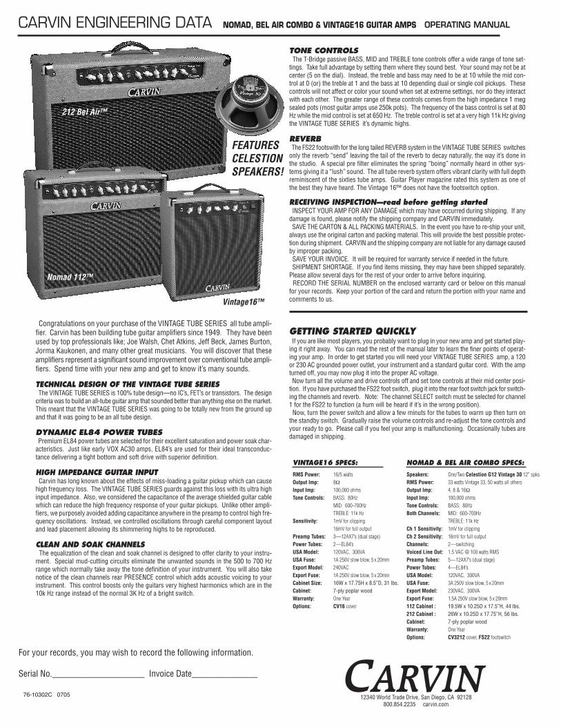
Congratulations on your purchase of the VINTAGE TUBE SERIES all tube ampli-fier. Carvin has been building tube guitar amplifiers since 1949. They have beenused by top professionals like; Joe Walsh, Chet Atkins, Jeff Beck, James Burton,Jorma Kaukonen, and many other great musicians. You will discover that theseamplifiers represent a significant sound improvement over conventional tube ampli-fiers. Spend time with your new amp and get to know it’s many sounds.
TECHNICAL DESIGN OF THE VINTAGE TUBE SERIESThe VINTAGE TUBE SERIES is 100% tube design—no IC’s, FET’s or transistors. The design
criteria was to build an all-tube guitar amp that sounded better than anything else on the market.This meant that the VINTAGE TUBE SERIES was going to be totally new from the ground upand that it was going to be an all tube design.
DYNAMIC EL84 POWER TUBESPremium EL84 power tubes are selected for their excellent saturation and power soak char-
acteristics. Just like early VOX AC30 amps, EL84’s are used for their ideal transconduc-tance delivering a tight bottom and soft drive with superior definition.
HIGH IMPEDANCE GUITAR INPUTCarvin has long known about the effects of miss-loading a guitar pickup which can cause
high frequency loss. The VINTAGE TUBE SERIES guards against this loss with its ultra highinput impedance. Also, we considered the capacitance of the average shielded guitar cablewhich can reduce the high frequency response of your guitar pickups. Unlike other ampli-fiers, we purposely avoided adding capacitance anywhere in the preamp to control high fre-quency oscillations. Instead, we controlled oscillations through careful component layoutand lead placement allowing its shimmering highs to be reproduced.
CLEAN AND SOAK CHANNELSThe equalization of the clean and soak channel is designed to offer clarity to your instru-
ment. Special mud-cutting circuits eliminate the unwanted sounds in the 500 to 700 Hzrange which normally take away the tone definition of your instrument. You will also takenotice of the clean channels rear PRESENCE control which adds acoustic voicing to yourinstrument. This control boosts only the guitars very highest harmonics which are in the10k Hz range instead of the normal 3K Hz of a bright switch.
TONE CONTROLSThe T-Bridge passive BASS, MID and TREBLE tone controls offer a wide range of tone set-
tings. Take full advantage by setting them where they sound best. Your sound may not be atcenter (5 on the dial). Instead, the treble and bass may need to be at 10 while the mid con-trol at 0 (or) the treble at 1 and the bass at 10 depending dual or single coil pickups. Thesecontrols will not affect or color your sound when set at extreme settings, nor do they interactwith each other. The greater range of these controls comes from the high impedance 1 megsealed pots (most guitar amps use 250k pots). The frequency of the bass control is set at 80Hz while the mid control is set at 650 Hz. The treble control is set at a very high 11k Hz givingthe VINTAGE TUBE SERIES it’s dynamic highs.
REVERBThe FS22 footswith for the long tailed REVERB system in the VINTAGE TUBE SERIES switches
only the reverb “send” leaving the tail of the reverb to decay naturally, the way it’s done inthe studio. A special pre filter eliminates the spring “boing” normally heard in other sys-tems giving it a “lush” sound. The all tube reverb system offers vibrant clarity with full depthreminiscent of the sixties tube amps. Guitar Player magazine rated this system as one ofthe best they have heard. The Vintage 16™ does not have the footswitch option.
RECEIVING INSPECTION—read before getting startedINSPECT YOUR AMP FOR ANY DAMAGE which may have occurred during shipping. If any
damage is found, please notify the shipping company and CARVIN immediately. SAVE THE CARTON & ALL PACKING MATERIALS. In the event you have to re-ship your unit,
always use the original carton and packing material. This will provide the best possible protec-tion during shipment. CARVIN and the shipping company are not liable for any damage causedby improper packing. SAVE YOUR INVOICE. It will be required for warranty service if needed in the future. SHIPMENT SHORTAGE. If you find items missing, they may have been shipped separately.
Please allow several days for the rest of your order to arrive before inquiring.RECORD THE SERIAL NUMBER on the enclosed warranty card or below on this manual
for your records. Keep your portion of the card and return the portion with your name andcomments to us.
GETTING STARTED QUICKLY If you are like most players, you probably want to plug in your new amp and get started play-
ing it right away. You can read the rest of the manual later to learn the finer points of operat-ing your amp. In order to get started you will need your VINTAGE TUBE SERIES amp, a 120or 230 AC grounded power outlet, your instrument and a standard guitar cord. With the ampturned off, you may now plug it into the proper AC voltage. Now turn all the volume and drive controls off and set tone controls at their mid center posi-
tion. If you have purchased the FS22 foot switch, plug it into the rear foot switch jack for switch-ing the channels and reverb. Note: The channel SELECT switch must be selected for channel1 for the FS22 to function (a hum will be heard if it’s in the wrong position). Now, turn the power switch and allow a few minuts for the tubes to warm up then turn on
the standby switch. Gradually raise the volume controls and re-adjust the tone controls andyour ready to go. Please call if you feel your amp is malfunctioning. Occasionally tubes aredamaged in shipping.
Nomad 112™
Vintage16™
c
FEATURESCELESTIONSPEAKERS!
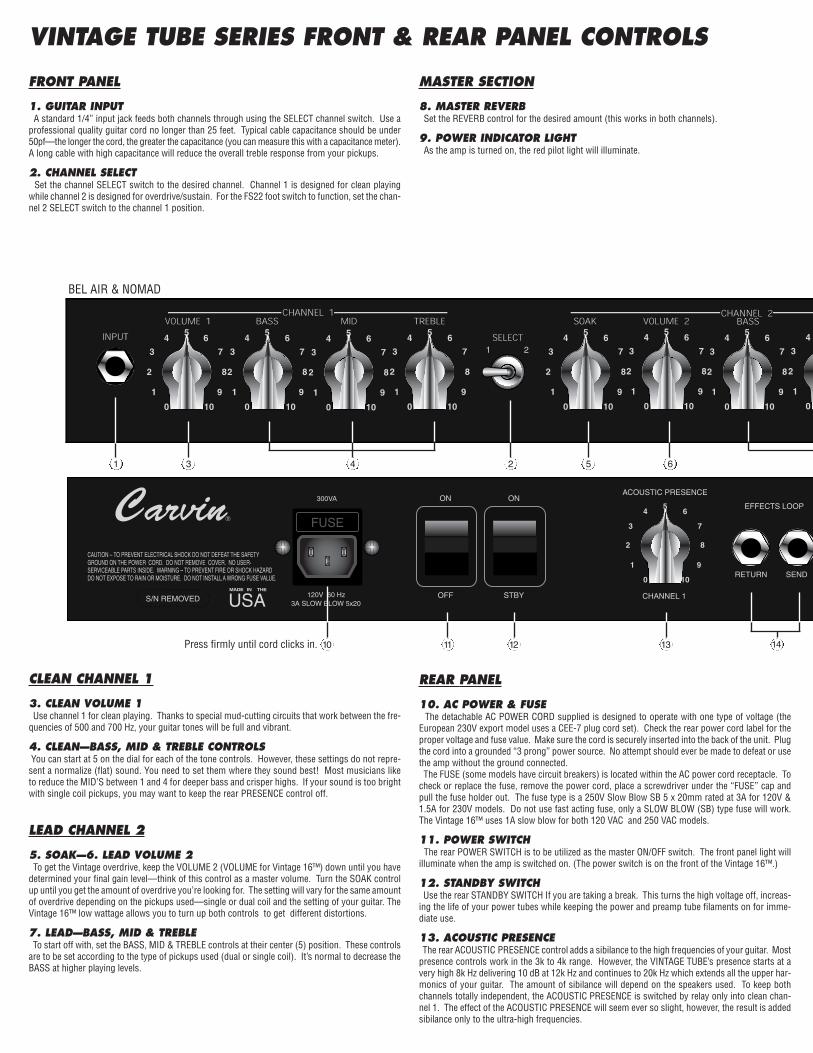
FRONT PANEL
1. GUITAR INPUT A standard 1/4” input jack feeds both channels through using the SELECT channel switch. Use a
professional quality guitar cord no longer than 25 feet. Typical cable capacitance should be under50pf—the longer the cord, the greater the capacitance (you can measure this with a capacitance meter).A long cable with high capacitance will reduce the overall treble response from your pickups.
2. CHANNEL SELECTSet the channel SELECT switch to the desired channel. Channel 1 is designed for clean playing
while channel 2 is designed for overdrive/sustain. For the FS22 foot switch to function, set the chan-nel 2 SELECT switch to the channel 1 position.
CLEAN CHANNEL 1
3. CLEAN VOLUME 1 Use channel 1 for clean playing. Thanks to special mud-cutting circuits that work between the fre-
quencies of 500 and 700 Hz, your guitar tones will be full and vibrant.
4. CLEAN—BASS, MID & TREBLE CONTROLSYou can start at 5 on the dial for each of the tone controls. However, these settings do not repre-sent a normalize (flat) sound. You need to set them where they sound best! Most musicians liketo reduce the MID’S between 1 and 4 for deeper bass and crisper highs. If your sound is too brightwith single coil pickups, you may want to keep the rear PRESENCE control off.
LEAD CHANNEL 2
5. SOAK—6. LEAD VOLUME 2To get the Vintage overdrive, keep the VOLUME 2 (VOLUME for Vintage 16™) down until you have
determined your final gain level—think of this control as a master volume. Turn the SOAK controlup until you get the amount of overdrive you’re looking for. The setting will vary for the same amountof overdrive depending on the pickups used—single or dual coil and the setting of your guitar. TheVintage 16™ low wattage allows you to turn up both controls to get different distortions.
7. LEAD—BASS, MID & TREBLETo start off with, set the BASS, MID & TREBLE controls at their center (5) position. These controls
are to be set according to the type of pickups used (dual or single coil). It’s normal to decrease theBASS at higher playing levels.
MASTER SECTION
8. MASTER REVERBSet the REVERB control for the desired amount (this works in both channels).
9. POWER INDICATOR LIGHTAs the amp is turned on, the red pilot light will illuminate.
REAR PANEL
10. AC POWER & FUSEThe detachable AC POWER CORD supplied is designed to operate with one type of voltage (the
European 230V export model uses a CEE-7 plug cord set). Check the rear power cord label for theproper voltage and fuse value. Make sure the cord is securely inserted into the back of the unit. Plugthe cord into a grounded “3 prong” power source. No attempt should ever be made to defeat or usethe amp without the ground connected.The FUSE (some models have circuit breakers) is located within the AC power cord receptacle. To
check or replace the fuse, remove the power cord, place a screwdriver under the “FUSE” cap andpull the fuse holder out. The fuse type is a 250V Slow Blow SB 5 x 20mm rated at 3A for 120V &1.5A for 230V models. Do not use fast acting fuse, only a SLOW BLOW (SB) type fuse will work.The Vintage 16™ uses 1A slow blow for both 120 VAC and 250 VAC models.
11. POWER SWITCHThe rear POWER SWITCH is to be utilized as the master ON/OFF switch. The front panel light will
illuminate when the amp is switched on. (The power switch is on the front of the Vintage 16™.)
12. STANDBY SWITCHUse the rear STANDBY SWITCH If you are taking a break. This turns the high voltage off, increas-
ing the life of your power tubes while keeping the power and preamp tube filaments on for imme-diate use.
13. ACOUSTIC PRESENCEThe rear ACOUSTIC PRESENCE control adds a sibilance to the high frequencies of your guitar. Most
presence controls work in the 3k to 4k range. However, the VINTAGE TUBE’s presence starts at avery high 8k Hz delivering 10 dB at 12k Hz and continues to 20k Hz which extends all the upper har-monics of your guitar. The amount of sibilance will depend on the speakers used. To keep bothchannels totally independent, the ACOUSTIC PRESENCE is switched by relay only into clean chan-nel 1. The effect of the ACOUSTIC PRESENCE will seem ever so slight, however, the result is addedsibilance only to the ultra-high frequencies.
VINTAGE TUBE SERIES FRONT & REAR PANEL CONTROLS
FUSE
2 531 64
BEL AIR & NOMAD
10 11 12 13 14Press firmly until cord clicks in.
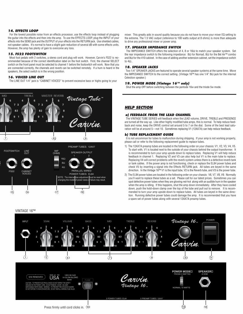
14. EFFECTS LOOPFor the lowest possible noise from an effects processor, use the effects loop instead of plugging
the guitar into the effects and then into the amp. To use the EFFECTS LOOP, plug the INPUT of youreffects into the SEND jack and the OUTPUT of your effects into the RETURN jack. Use shielded cables,not speaker cables. It’s normal to have a slight gain reduction of several dB with some effects units.However, the amp has plenty of gain to overcome any loss.
15. FS22 FOOTSWITCHMost foot pedals with 2 switches, a stereo cord and plug will work. However, Carvin’s FS22 is rec-
ommended because of the correct identification label on the foot switch. First, the channel SELECTswitch on the front panel must be selected to channel 1 before the footswitch will work. Now that youare connected correctly, the channels and reverb can be switched remotely. If a hum is heard in thespeakers, the select switch is in the wrong position.
16. VOICED LINE OUTThe LINE OUT 1/4” jack is “CABINET VOICED” to prevent excessive bass or highs going to your
mixer. This greatly aids in sound quality because you do not have to move your mixer EQ setting tothe extreme. The 1.5 VAC output (reference to 100 watts output at 8 ohms) is more than adequateto drive any professional mixer or power amp.
17. SPEAKER IMPEDANCE SWITCHThe IMPEDANCE SWITCH offers the selection of 4, 8 or 16Ω to match your speaker system. Set
the rear impedance switch to the following impedance: 8Ω for Nomad, 8Ω for the Bel Air™ comboand 8Ω for the 410 cabinet. In the case of adding another extension cabinet, set the impedance switchto 4Ω..
18. SPEAKER JACKSTwo 1/4” SPEAKER JACKS are featured to operate several speaker systems at the same time. Move
the IMPEDANCE SWITCH to the correct setting. (Vintage 16™ has one 1/4” 8Ω jack for the internalCelestion speaker.)
19. POWER MODE (Vintage 16™ only)Shut the amp OFF before switching between the pentode 16w and the triode 5w mode.
HELP SECTION
a) FEEDBACK FROM THE LEAD CHANNELThe VINTAGE TUBE SERIES will feedback when the LEAD volume, DRIVE, TREBLE and PRESENCE
are turned all the way up. Like other highly modified tube amps, this is normal. To help reduce feed-back and noise, keep the DRIVE control set around 5 to 7 on the dial. Some of the best lead satu-ration will be at around 5—not 10. Sometimes replacing V1 (12AX7A) can help reduce feedback.
b) TUBE REPLACEMENT GUIDE It is not uncommon for tubes to malfunction during shipping. If your amp is not working properly,
please call or refer to the following replacement guide to replace tubes.
1) The 12AX7A preamp tubes are located in the following order on your chassis: V1, V2, V3, V4, V5.To start with, V1 is located next to the outside of your chassis behind the output transformer. Itis recommended to turn your amp upside down to replace tubes. Replacing V1 will help reducefeedback in channel 1. Replacing V2 and V3 can also help but V1 is the main tube to replace.Replacing V4 will correct problems with the reverb system unless there is a defective reverb tankor tank cables. If the power amp is not functioning, check or replace the EL84 power tubes andcheck V5 by inserting a signal into the Effects RETURN jack. All tubes are keyed in the samedirection. In the Vintage 16™ V1 is the input tube, V2 is the Reverb tube, and V3 is the power tube.
2) The EL84 power tubes are located in the following order on your chassis: V6, V7, V8, V9. Normallyyou’ll want to replace these tubes as a set. Please call for our latest prices. Sometimes you canspot defective power tubes when they are glowing red-hot along with an audible hum in the speakerwhen the amp is idling. If this happens, shut the amp down immediately. After they have cooleddown, push the hold-down clamp over the top of the tube and pull out to remove. It is recom-mended to turn your amp upside down to replace tubes. All tubes are keyed in the same direc-tion. Running defective power tubes could damage the amp. It is recommended that you havea spare set of power tubes along with several 12AX7A preamp tubes.
987
15 16 17 18
120V 60 Hz1A SLOW BLOW
60VA FUSE
3 POWER TUBES: EL84 3 PREAMP TUBES: 12AX7
POWER MODETRIODE 6 WATTS
NORMAL 15 WATTS
SPEAKER8 OHM
9875 61 11
1810 19
VINTAGE 16™
Press firmly until cord clicks in.

CAUTIONRISK OF ELECTRIC SHOCK
DO NOT OPEN
SAFETY INSTRUCTIONS (EUROPEAN)The conductors in the AC power cord are colored in accordance with the following code.GREEN & YELLOW—Earth BLUE—Neutral BROWN—LiveU.K. MAIN PLUG WARNING: A molded main plug that has been cut off from the cord isunsafe. NEVER UNDER ANY CIRCUMSTANCES SHOULD YOU INSERT A DAMAGEDOR CUT MAIN PLUG INTO A POWER SOCKET.
IMPORTANT! FOR YOUR PROTECTION, PLEASE READ THE FOLLOWING:WATER AND MOISTURE: Appliance should not be used near water (near a bathtub, washbowl,kitchen sink, laundry tub, in a wet basement, or near a swimming pool, etc). Care should be takenso that objects do not fall and liquids are not spilled into the enclosure through openings.POWER SOURCES: The appliance should be connected to a power supply only of the type describedin the operating instructions or as marked on the appliance.GROUNDING OR POLARIZATION: Precautions should be taken so that the grounding or polar-ization means of an appliance is not defeated.POWER CORD PROTECTION: Power supply cords should be routed so that they are not likelyto be walked on or pinched by items placed upon or against them, paying particular attentionto cords at plugs, convenience receptacles, and the point where they exit from the appliance.SERVICING: The user should not attempt to service the appliance beyond that described in theoperating instructions. All other servicing should be referred to qualified service personnel.FUSING: If your unit is equipped with a fuse receptacle, replace only with the same type fuse.Refer to replacement text on the unit for correct fuse type.
This symbol is intended toalert the user to the pres-ence of uninsulated “dan-gerous voltage” within the
product’s enclosure that may be of suf-ficient magnitude to constitute a risk ofelectric shock to persons.
This symbol isintended to alert theuser to the presence ofimportant operatingand maintenance (servicing) instruc-tions in the literature accompanyingthe appliance.
LIMITED WARRANTYYour Carvin product is guaranteed against failure for ONE YEAR unless otherwise stated. Vacuum
tubes are guaranteed for 90 days. Carvin will service and supply all parts at no charge to the customerproviding the unit is under warranty. Shipping costs are the responsibility of the customer. CARVINDOES NOT PAY FOR PARTS OR SERVICING OTHER THAN OUR OWN. A COPY OF THE ORIGINALINVOICE IS REQUIRED TO VERIFY YOUR WARRANTY. Carvin assumes no responsibility for horn dri-vers or speakers damaged by this unit. This warranty does not cover, and no liability is assumed, fordamage due to: natural disasters, accidents, abuse, loss of parts, lack of reasonable care, incorrectuse, or failure to follow instructions. This warranty is in lieu of all other warranties, expressed or implied.No representative or person is authorized to represent or assume for Carvin any liability in connectionwith the sale or servicing of Carvin products. CARVIN SHALL NOT BE LIABLE FOR INCIDENTAL ORCONSEQUENTIAL DAMAGES. When RETURNING merchandise to the factory, you may call for a return authorization number. Describe
in writing each problem. If your unit is out of warranty, you will be charged the current FLAT RATE forparts and labor to bring your unit up to factory specifications.
HELP SECTION1) AMP WILL NOT TURN ON
Check the power to the amp. Check for tripped circuit breakers, unplugged extension cords or power-strip switches that may be turned off. Check the fuse. If a dark brownish color or no wire can beseen within the glass tube, then replace. The amp may be perfectly fine but occasionally a fusemay blow because of high AC voltage surges. After the fuse has been replaced with the properSlow Blow value and if the fuse fails again, the amp will require servicing.
2) NO OUTPUT with POWER LIGHT ONTubes damaged in shipping will be the primary reason for your amp to not function properly. Pleasegive us a call to help guide you through this simple repair.
3) KEEP YOUR AMP LOOKING NEWUse a damp cloth to wipe the controls on the front & rear chassis panels. Wipe the black vinyl cov-ering with a damp cloth.
REFER SERVICING TO QUALIFIED SER-VICE PERSONNEL! THIS UNIT CON-TAINS HIGH VOLTAGE INSIDE!
CAUTIONRISK OF ELECTRIC SHOCK
Ref. # Description Carvin PN
B1 Junper, 0.5”, 0Ω 51-00050B2 Junper, 0.35”, 0Ω 50-00035B3 Junper, 0.5”, 0Ω 51-00050B4 Junper, 0.5”, 0Ω 51-00050B5 Junper, 0.5”, 0Ω 51-00050B7 Junper, 0.35”, 0Ω 50-00035B9 Junper, 0.5”, 0Ω 51-00050B10 Junper, 0.5”, 0Ω 51-00050B11 Junper, 0.35”, 0Ω 50-00035B12 Junper, 0.35”, 0Ω 50-00035B13 Junper, 0.35”, 0Ω 50-00035B14 Junper, 0.35”, 0Ω 50-00035B15 Junper, 0.35”, 0Ω 50-00035B16 Junper, 0.8”, 0Ω 44-18000B17 Junper, 0.5”, 0Ω 51-00050B18 Junper, 0.35”, 0Ω 50-00035B19 Junper, 0.5”, 0Ω 51-00050B20 Junper, 0.35”, 0Ω 50-00035B22 Junper, 0.35”, 0Ω 50-00035B23 Junper, 0.8”, 0Ω 44-18000B24 Junper, 0.35”, 0Ω 50-00035B25 Junper, 0.35”, 0Ω 50-00035B26 Junper, 0.35”, 0Ω 50-00035B27 Junper, 0.35”, 0Ω 50-00035B28 Junper, 0.35”, 0Ω 50-00035B29 Junper, 0.5”, 0Ω 51-00050B30 Junper, 0.5”, 0Ω 51-00050B31 Junper, 0.5”, 0Ω 51-00050B32 Junper, 0.8”, 0Ω 44-18000B33 Junper, 0.8”, 0Ω 44-18000B34 Junper, 0.5”, 0Ω 51-00050B35 Junper, 0.35”, 0Ω 50-00035B36 Junper, 0.35”, 0Ω 50-00035B37 Junper, 0.35”, 0Ω 50-00035B50 Junper, 0.5”, 0Ω 51-00050C1 Capacitor, Electrolytic, 10µF 50V, 20% 47-10051C2 Capacitor, Poly, 0.01µF 100V, 10% 46-10312C4 Capacitor, Poly, 0.001µF 100V, 10% 46-10212C5 Capacitor, Poly, 0.033µF 100V, 10% 46-33312C6 Capacitor, Ceramic, 120PF 500V, 10% 45-12152C7 Capacitor, Poly, 0.01µF 100V, 10% 46-10312C8 Capacitor, Electrolytic, 10µF 50V, 20% 47-10051C9 Capacitor, Mylar, 0.047µF 400V, 10% 41-47342C10 Not UsedC11 Capacitor, Electrolytic, 10µF 50V, 20% 47-10051C12 Capacitor, Poly, 0.0033µF 100V, 10% 46-33212C13 Capacitor, Ceramic, 250PF 500V, 5% 45-25152C14 Capacitor, Ceramic, 560PF 500V, 10% 45-56152C15 Not UsedC16 Capacitor, Ceramic, 0.0047µF 400V, 10% 41-47242C17 Capacitor, Electrolytic, 10µF 50V, 20% 47-10051C18 Capacitor, Mylar, 0.047µF 400V, 10% 41-47342C19 Capacitor, Ceramic, 120PF 500V, 10% 45-12152C20 Capacitor, Poly, 0.022µF 100V, 10% 46-22312C21 Capacitor, Poly, 0.0022µF 100V, 10% 46-22212C22 Capacitor, Poly, 0.0022µF 100V, 10% 46-22212C23 Not UsedC24 Not UsedC25 Capacitor, Poly, 0.047µF 100V, 10% 46-47312C26 Capacitor, Ceramic, 82PF 500V, 5% 45-82052C27 Capacitor, Electrolytic, 10µF 50V, 20% 47-10051C28 Capacitor, Mylar, 0.047µF 400V, 10% 41-47342C29 Capacitor, Poly, 0.0022µF 100V, 10% 46-22212C30 Capacitor, Electrolytic, 10µF 50V, 20% 47-10051C31 Capacitor, Poly, 0.0022µF 100V, 10% 46-22212C32 Not UsedC33 Capacitor, Poly, 0.001µF 100V, 10% 46-10212C34 Capacitor, Ceramic, 56PF 500V, 5% 45-56052C35 Capacitor, Poly, 0.047µF 100V, 10% 46-47312C36 Capacitor, Mylar, 0.047µF 400V, 10% 41-47342C37 Capacitor, Mylar, 0.047µF 400V, 10% 41-47342
Ref. # Description Carvin PN
C38 Capacitor, Electrolytic, 47µF 63V, 20% 47-47061C39 Capacitor, Mylar, 0.047µF 630V, 10% 46-47362C40 Capacitor, Electrolytic, 22µF 500V, 20% 42-20052C41 Capacitor, Electrolytic, 22µF 500V, 20% 42-20052C42 Capacitor, Electrolytic, 22µF 500V, 20% 42-20052C43 Capacitor, Electrolytic, 22µF 500V, 20% 42-20052C44 Capacitor, Electrolytic, 22µF 500V, 20% 42-20052C45 Capacitor, Electrolytic, 2200uF 6.3V, 20% 47-22260C46 Capacitor, Electrolytic, 2200uF 6.3V, 20% 47-22260C47 Capacitor, Electrolytic, 2200uF 6.3V, 20% 47-22260C48 Capacitor, Mylar, 0.047µF 630V, 10% 46-47362C49 Not UsedC50 Capacitor, Poly, 0.0022µF 100V, 10% 46-22212C70 Capacitor, Poly, 0.01µF 100V, 10% 46-10312C71 Capacitor, Ceramic, 180PF 500V, 10% 45-18152C72 Capacitor, Ceramic, 120PF 500V, 10% 45-12152D1 Diode, 1N4745A 16V, 1W 60-47450D2 Diode, 1N4745A 16V, 1W 60-47450D3 Diode, 1N4745A 16V, 1W 60-47450D4 Diode, 1N4745A 16V, 1W 60-47450D5 Diode, 1N4003 200V, 1A 60-40030D6 Diode, 1N4007A 1000V, 1A 60-10000D7 Diode, 1N4007A 1000V, 1A 60-10000D8 Diode, 1N4007A 1000V, 1A 60-10000D9 Diode, 1N4007A 1000V, 1A 60-10000D10 Diode, 1N4007A 1000V, 1A 60-10000D11 Diode, 1N4007A 1000V, 1A 60-10000D12 Diode, 1N4007A 1000V, 1A 60-10000D13 Diode, 1N4007A 1000V, 1A 60-10000D14 Diode, 1N4007A 1000V, 1A 60-10000D15 Diode, 1N4007A 1000V, 1A 60-10000D16 Diode, 1N4007A 1000V, 1A 60-10000D20 Not UsedD21 Not UsedF1 Fuse Clips, (1 pair) 23-03529
Fuse 1AGC Fast 70-21010F2 Fuse Clips, (1 pair) 23-03529
Fuse 10A Slow 70-22101F3 Fuse Clips, (1 pair) 23-03529
Fuse 1AGC Fast 70-21010G1 Ferrite Bead 15-27430H1A Cable 10” 2 conductor + Shield 05-00110H2A Conn. Header, 2 Pin Vert, SHS 23-11002H2B Conn. Header, 2 Pin Vert, SHS 23-11002H3A Conn. Header, 4 Pin Vert, SHS 23-11004H3B Conn. Header, 4 Pin Vert, SHS 23-11004H5 Wire 10”, 18GA (Pair) 04-18010H6 Wire 4”, 18GA (Pair) 04-18040H7A Conn. Header, 2 Pin Vert, SHS 23-11002H7B Conn. Header, 2 Pin Vert, SHS 23-11002H8A Conn. Header, 2 Pin Vert, SHS 23-11002H8B Conn. Header, 2 Pin Vert, SHS 23-11002J1 Phone Jack, 1/4, 90° Rev Threaded Neck 21-01804J2 Phone Jack, 1/4, 3 Pin Plastic, 24mm 21-06453J3 Phone Jack, 1/4, 3 Pin Plastic, 24mm 21-06453J4 Phone Jack, 1/4, 3 Pin Plastic, 24mm 21-06453J5 Phone Jack, 1/4, 7 Pin Plastic Stereo, 24mm 21-06457L1 Relay 3V PCB MNT, 5V DPDT 70-05303L2 Relay 3V PCB MNT, 5V DPDT 70-05303P1 Potentiometer, B100K, O Shaft, 16mm, RX250 90° 71-14052P2 Potentiometer, B1MEG, O Shaft, 16mm, RX250 90° 71-14070P3 Potentiometer, 25A25K, O Shaft, 16mm, RX250 90° 71-14050P4 Potentiometer, B1MEG, O Shaft, 16mm, RX250 90° 71-14070P5 Potentiometer, 5A500K, O Shaft, 16mm, RX250 90° 71-14060P6 Potentiometer, B100K, O Shaft, 16mm, RX250 90° 71-14052P7 Potentiometer, B1MEG, O Shaft, 16mm, RX250 90° 71-14070P8 Potentiometer, 25A25K, O Shaft, 16mm, RX250 90° 71-14050P9 Potentiometer, B100K, O Shaft, 16mm, RX250 90° 71-14052P10 Potentiometer, B100K, O Shaft, 16mm, RX250 90° 71-14052P11 Potentiometer, Trimmer, 20K PCB MTG 71-22012P21 Potentiometer, 25A15K-C, O Shaft, 16mm, RX250 90° 71-14048
Ref. # Description Carvin PN
QC1 Spade Terminal, QC Vertical, 0.205 06-40045QC2 Spade Terminal, QC Vertical, 0.205 06-40045QC3 Spade Terminal, QC Vertical, 0.205 06-40045QC4 Spade Terminal, QC Vertical, 0.205 06-40045QC6A Spade Terminal, QC Vertical, 0.250 06-40050QC6B Spade Terminal, QC Vertical, 0.250 06-40050QC7 Spade Terminal, QC Vertical, 0.250 06-40050QC8 Spade Terminal, QC Vertical, 0.250 06-40050QC9 Spade Terminal, QC Vertical, 0.250 06-40050QC13ASpade Terminal, QC Vertical, 0.250 06-40050QC13BSpade Terminal, QC Vertical, 0.250 06-40050QC14 Spade Terminal, QC Vertical, 0.250 06-40050QC31 Spade Terminal, QC Vertical, 0.250 06-40050QC32 Spade Terminal, QC Vertical, 0.250 06-40050QC33 Spade Terminal, QC Vertical, 0.250 06-40050QC35 Spade Terminal, QC Vertical, 0.250 06-40050QC36 Spade Terminal, QC Vertical, 0.250 06-40050QC37 Spade Terminal, QC Vertical, 0.250 06-40050R1 Resistor, 100K, .35 Prep., 5% Carbon, 1/4W 50-10055R2 Resistor, 1.5K, .35 Prep., 5% Carbon, 1/4W 50-15035R3 Resistor, 220K, .35 Prep., 5% Carbon, 1/4W 50-22055R4 Resistor, 150K, .35 Prep., 5% Carbon, 1/4W 50-15055R5 Resistor, 100K, .35 Prep., 5% Carbon, 1/4W 50-10055R6 Resistor, 1.5K, .35 Prep., 5% Carbon, 1/4W 50-15035R7 Resistor, 220K, .35 Prep., 5% Carbon, 1/4W 50-22055R8 Resistor, 1.5K, .35 Prep., 5% Carbon, 1/4W 50-15035R9 Resistor, 220K, .35 Prep., 5% Carbon, 1/4W 50-22055R10 Resistor, 4.7K, .35 Prep., 5% Carbon, 1/4W 50-47035R11 Resistor, 220K, .35 Prep., 5% Carbon, 1/4W 50-22055R12 Resistor, 47K, .35 Prep., 5% Carbon, 1/4W 50-47045R13 Resistor, 1K, .35 Prep., 5% Carbon, 1/4W 50-10035R14 Resistor, 220K, .35 Prep., 5% Carbon, 1/4W 50-22055R15 Resistor, 47K, .35 Prep., 5% Carbon, 1/4W 50-47045R16 Resistor, 10K, .35 Prep., 5% Carbon, 1/4W 50-10045R17 Resistor, 22K, .35 Prep., 5% Carbon, 1/4W 50-22045R18 Resistor, 100K, .35 Prep., 5% Carbon, 1/4W 50-10055R19 Resistor, 220Ω, .35 Prep., 5% Carbon, 1/4W 50-22025R20 Resistor, 2.2M, .35 Prep., 5% Carbon, 1/4W 50-22065R21 Resistor, 47K, 0.8 Prep., 5% Carbon 1W 53-47045R22 Resistor, 2.2M, .35 Prep., 5% Carbon, 1/4W 50-22065R23 Resistor, 220K, .35 Prep., 5% Carbon, 1/4W 50-22055R24 Resistor, 1.5K, .35 Prep., 5% Carbon, 1/4W 50-15035R25 Resistor, 220K, .35 Prep., 5% Carbon, 1/4W 50-22055R26 Resistor, 1M, .35 Prep., 5% Carbon, 1/4W 50-10065R27 Resistor, 22K, .35 Prep., 5% Carbon, 1/4W 50-22045R28 Resistor, 1.5K, .35 Prep., 5% Carbon, 1/4W 50-15035R29 Resistor, 220K, .35 Prep., 5% Carbon, 1/4W 50-22055R30 Resistor, 100K, .35 Prep., 5% Carbon, 1/4W 50-10055R31 Resistor, 560Ω, .35 Prep., 5% Carbon, 1/4W 50-56025R32 Resistor, 100K, .35 Prep., 5% Carbon, 1/4W 50-10055R33 Resistor, 22K, .35 Prep., 5% Carbon, 1/4W 50-22045R34 Resistor, 22K, .35 Prep., 5% Carbon, 1/4W 50-22045R35 Resistor, 100K, .35 Prep., 5% Carbon, 1/4W 50-10055R36 Resistor, 100K, .35 Prep., 5% Carbon, 1/4W 50-10055R37 Resistor, 220K, .35 Prep., 5% Carbon, 1/4W 50-22055R38 Resistor, 220K, .35 Prep., 5% Carbon, 1/4W 50-22055R39 Resistor, 3.9K, .35 Prep., 5% Carbon, 1/4W 50-39035R40 Resistor, 100K, .35 Prep., 5% Carbon, 1/4W 50-10055R41 Resistor, 4.7K, .35 Prep., 5% Carbon, 1/4W 50-47035R42 Resistor, 2.2K, .35 Prep., 5% Carbon, 1/4W 50-22035R43 Resistor, 350Ω., SDOF, 10% Sand Bar,10W 56-35010R44 Resistor, 100Ω, 0.35 Prep., 1% Metal, 1/4W 50-10021R45 Resistor, 100Ω, 0.35 Prep., 1% Metal, 1/4W 50-10021R46 Resistor, 10Ω, 0.5 Prep., 5% Carbon, 1/2W 52-10015R49 Resistor, 100K, .35 Prep., 5% Carbon, 1/4W 50-10055R50 Resistor, 1MEG, .35 Prep., 5% Carbon, 1/4W 50-10065R57 Resistor, 4.7K, .35 Prep., 5% Carbon, 1/4W 50-47035R60 Resistor, 56K, .35 Prep., 5% Carbon, 1/4W 50-56045R61 Resistor, 56K, .35 Prep., 5% Carbon, 1/4W 50-56045R62 Resistor, 350Ω, .35 Prep., 5% Carbon, 1/4W 50-35025R63 Resistor, 350Ω, .35 Prep., 5% Carbon, 1/4W 50-35025
Ref. # Description Carvin PN
R64 Resistor, 56K, .35 Prep., 5% Carbon, 1/4W 50-56045R65 Resistor, 56K, .35 Prep., 5% Carbon, 1/4W 50-56045R66 Resistor, 350Ω, .35 Prep., 5% Carbon, 1/4W 50-35035R67 Resistor, 350Ω, .35 Prep., 5% Carbon, 1/4W 50-35035R70 Resistor, 2.2K, .35 Prep., 5% Carbon, 1/4W 50-22035R71 Resistor, 10K, .35 Prep., 5% Carbon, 1/4W 50-10035R72 Resistor, 470K, .35 Prep., 5% Carbon, 1/4W 50-47045R73 Resistor, 22K, .35 Prep., 5% Carbon, 1/4W 50-22045S1 Switch, DP3T Lift Tall Bat, PCB MTG 25-76286
Switch, Channel Select, SPST toggle, Chassis MTG 25-75801Switch, Power, LG DPDT, Chassis MTG 25-31350Switch, Stand-by, LG DPDT, Chassis MTG 25-31350
SPK1 Phone Jack, 1/4, 3 Pin Plastic, 24mm 21-06453SPK2 Phone Jack, 1/4, 3 Pin Plastic, 24mm 21-06453
Vintage Tube 50, 120V Transformer, Chassis MTG 15-10640Vintage Tube 50, Output Transformer, Chassis MTG 15-02066
V1 Socket for 12AX7A/EL84 12VAC, 9 Pin, SIN/RUS 23-91632Vacuum Tube, Type Tube 12AX7A 65-00127
V2 Socket for 12AX7A/EL84 12VAC, 9 Pin, SIN/RUS 23-91632Vacuum Tube, Type Tube 12AX7A 65-00127
V3 Socket for 12AX7A/EL84 12VAC, 9 Pin, SIN/RUS 23-91632Vacuum Tube, Type Tube 12AX7A 65-00127
V4 Socket for 12AX7A/EL84 12VAC, 9 Pin, SIN/RUS 23-91632Vacuum Tube, Type Tube 12AX7A 65-00127
V5 Socket for 12AX7A/EL84 12VAC, 9 Pin, SIN/RUS 23-91632Vacuum Tube, Type Tube 12AX7A 65-00127
V6 Socket for 12AX7A/EL84 12VAC, 9 Pin, SIN/RUS 23-91632Vacuum Tube, Type Tube EL84 65-00084
V7 Socket for 12AX7A/EL84 12VAC, 9 Pin, SIN/RUS 23-91632Vacuum Tube, Type Tube EL84 65-00084
V8 Socket for 12AX7A/EL84 12VAC, 9 Pin, SIN/RUS 23-91632Vacuum Tube, Type Tube EL84 65-00084
V9 Socket for 12AX7A/EL84 12VAC, 9 Pin, SIN/RUS 23-91632Vacuum Tube, Type Tube EL84 65-00084
REPLACEMENT PARTS LIST (for circuit cards)