Capacitors for Use in Electronics - Iskra · on Iskra Capacitors for use in electronics. 4 Type...
40
1 Capacitors for Use in Electronics Capacitors
Transcript of Capacitors for Use in Electronics - Iskra · on Iskra Capacitors for use in electronics. 4 Type...
1
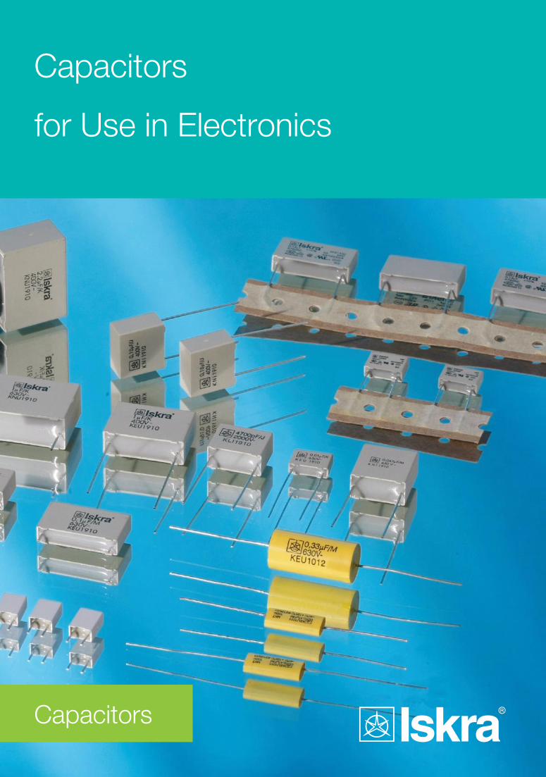
Capacitors
for Use in Electronics
Capacitors

3
Type Construction of capacitors Class Page
KFU polyester capacitors (KT) 13
KEU metallized polyester capacitors (MKT) 16
KLI polypropylene capacitors (KP) 24
KNI metallized polypropylene capacitors (MKP) 29
KNU metallized polypropylene capacitors (MKP) 36
Contents
General information on Iskra Capacitors for use in electronics
4
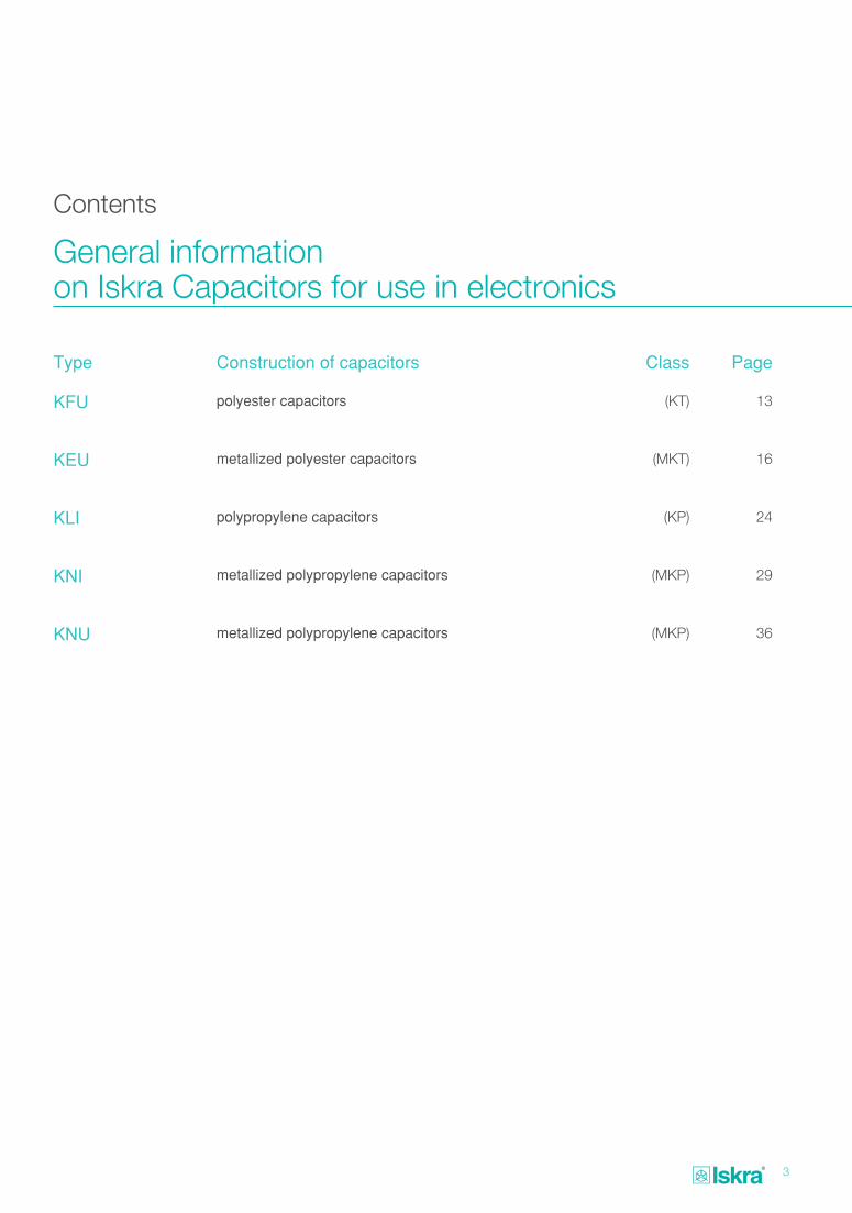
Type Version Pitch (mm) Dielectric Capacitence range Rated voltage Page
KFU1910 10; 15; 22,5; 27,5Polyester film
(KT)
0,022 μF — 1 μF0,015 μF — 0,47 μF4700 pF — 0,33 μF1000 pF — 0,22 μF1000 pF — 0,068 μF
100 V DC250 V DC400 V DC630 V DC1000 V DC
14
KEU1930
KEU1930 taped
7,5Metallized
polyester film (MKT)
0,068 μF — 1 μF 0,033 μF — 0,33 μF 0,01 μF — 0,15 μF
4700 pF — 0,033 μF 1000 pF — 0,015 μF
63 V DC100 V DC250 V DC400 V DC630 V DC
17
KEU1910 10; 15; 22,5; 27,5Metallized
polyester film (MKT)
0,22 μF — 22 μF 0,068 μF — 10 μF 0,033 μF — 10 μF 0,01 μF — 4,7 μF 4700 pF — 1,5 μF 1000 pF — 0,68 μF
63 V DC 100 V DC250 V DC400 V DC630 V DC1000 V DC
19
KEU1012
axial leadsMetallized
polyester film (MKT)
0,15 μF — 10 μF 0,068 μF — 10 μF 0,047 μF — 10 μF 0,01 μF — 3,3μF 1000 pF — 1μF
1000 pF — 0,47 μF
63 V DC100 V DC250 V DC400 V DC630 V DC1000 V DC
22
KLI1910 7,5;10;
15; 22,5; 27,5
Polypropylene film(KP)
6800 pF — 0,15 μF3300 pF — 0,1 μF
2200 pF — 0,047 μF1000 pF — 0,047 μF 100 pF — 0,22 μF 1000 pF — 0,22 μF 1000 pF — 0,1 μF
1000 pF — 0,047 μF
100 V DC160 V DC250 V DC400 V DC630V DC
1000 V DC1600 V DC2000 V DC
25
KNI1910
7,5; 10; 15; 22,5
Metallized polypropylene
film(MKP)
680 pF — 2,2 μF680 pF — 1,8 μF680 pF — 0,39 μF3300 pF — 0,33 μF1000 pF — 0,15 μF1000 pF — 0,1 μF
250 V DC400 V DC 630 V DC1000 V DC1600 V DC2000 V DC
30
KNU1910
10; 15; 22,5; 27,5
Metallized polypropylene
film(MKP)
0,022 μF — 6,8 μF 0,01 μF — 2,2 μF 4700 pF — 1 μF 0,01 μF — 1 μF
1000 pF — 0,33 μF
250 V DC400 V DC630 V DC1000 V DC1600 V DC
37
Contents
5
General technical data
ISKRA capacitors for use in electronics are made of dielectric materials as follow: - polypropylene film - polyester
(polyethyleneterephtalate).
Survey of specific properties of individual dielectrics and use:
Polyester (polyethylenete-rephtalate) film
Dielectric constant (25 °C/1 kHz): εr = 3,25; ASTM D 150-65T
Dielectric loss (25 °C/60 Hz): tanδ ≤ 20,10-4 C; ASTM D 150-65T
Dielectric strength (25 °C/60 Hz): 295 kV/mm; ASTM D 149-64,
ASTM D 2305-67
Temperature coefficient of capacitance: TC ≈ + 500, 10-6 C/°C
Temperature range max.: + 125 °C
Water absorption (sink for 24 h): 0,8 % max.; ASTM D 570-63
Dielectric absorption: 0,2 to 0,8 %
Polyester capacitors are used mainly in electronic devices where special characteristics of electrical parameters are not required and where wider temperature range is required. Mainly they are used as conjuctive or block capacitors.
Polypropylene film
Dielectric constant (25 °C/1 kHz): εr = 2,2; ASTM D 150
Dielectric loss (25 °C/1 kHz): tanδ ≤ 5,10-4 C; ASTM D 150
Dielectric strength (25 °C/1 kHz): 300 to 380 kV/mm; ASTM D 149
Temperature coefficient of capacitance: (- 100 ≤ TC ≤ -300) ,10-6/°C
Temperature range max.: + 100 °C
Water absorption:< 0,05 %; ASTM D 202
Dielectric absorption: 0,03 %
Polypropylene capacitors are used mainly in electronic circuits, where following requirements appear:
- small dielectric losses
- high insulation resistance
- negative and defined temperature coefficient (temperature compensation at oscillating circles with ferrite coil)
- high pulse loading
- loading with AC voltage.
Designation of dielectric in type code of capacitors
Type code is composed by three letters and four figures:
K X X Y Y Y Y
↓ ↓ ↓ ↓ ↓ ↓ ↓
1 2 3 4 5 6 7
1st Letter, “K” means capacitor
2nd Letter tells the type of dielectric (special for metallized version)
3rd Letter tells the purpose of use
4th, 5th, 6th, 7th Figure describes construction and design of capacitor and leads
Survey of letter used for single kinds of dielectric:
F - polyester film
E - metallized polyester film
L - polypropylene film
N - metallized polypropylene film
Electrical characteristics
1. Rated capacitance
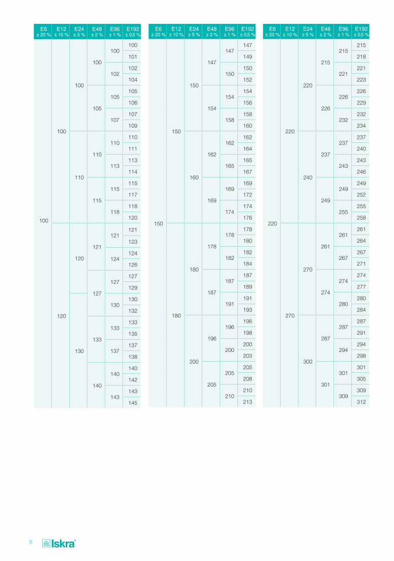
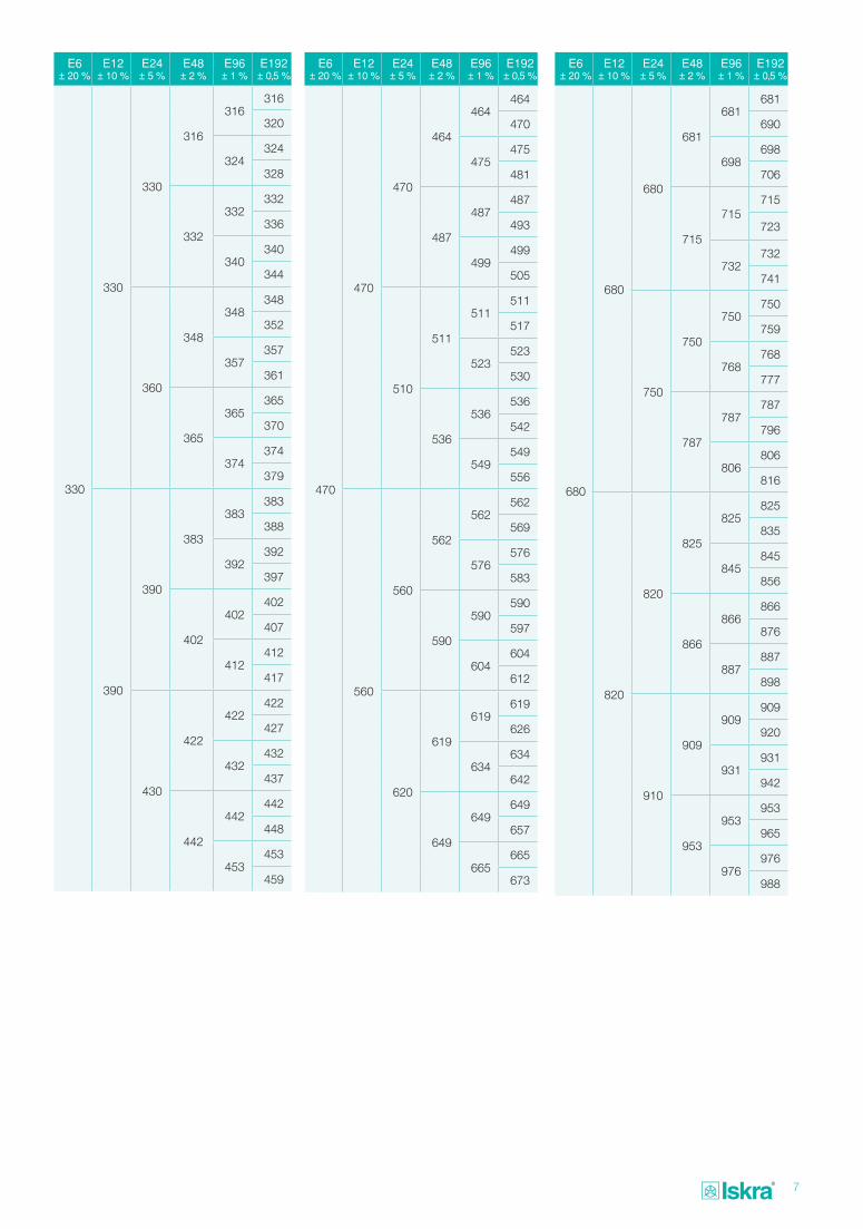
Rated capacitance CR values are available according to E-ranges. Available E-ranges (E6, E12, E24, E48, E96, on request E192) are stated at type descriptions in catalogue. The values from range E6 are privileged.
The E-ranges are put down in accordance to IEC-publ. 60063 and DIN 41426.
Required values from E-range are all values from table below, multiplied by positive or negative whole number power exponent of the number 10.
6
E6± 20 %
E12± 10 %
E24± 5 %
E48± 2 %
E96± 1 %
E192± 0,5 %
150
150
150
147
147147
149
150150
152
154
154154
156
158158
160
160
162
162162
164
165165
167
169
169169
172
174174
176
180
180
178
178178
180
182182
184
187
187187
189
191191
193
200
196
196196
198
200200
203
205
205205
208
210210
213
E6± 20 %
E12± 10 %
E24± 5 %
E48± 2 %
E96± 1 %
E192± 0,5 %
220
220
220
215
215215
218
221221
223
226
226226
229
232232
234
240
237
237237
240
243243
246
249
249249
252
255255
258
270
270
261
261261
264
267267
271
274
274274
277
280280
284
300
287
287287
291
294294
298
301
301301
305
309309
312
E6± 20 %
E12± 10 %
E24± 5 %
E48± 2 %
E96± 1 %
E192± 0,5 %
100
100
100
100
100100
101
102102
104
105
105105
106
107107
109
110
110
110110
111
113113
114
115
115115
117
118118
120
120
120
121
121121
123
124124
126
127
127127
129
130
130130
132
133
133133
135
137137
138
140
140140
142
143143
145
7
E6± 20 %
E12± 10 %
E24± 5 %
E48± 2 %
E96± 1 %
E192± 0,5 %
330
330
330
316
316316
320
324324
328
332
332332
336
340340
344
360
348
348348
352
357357
361
365
365365
370
374374
379
390
390
383
383383
388
392392
397
402
402402
407
412412
417
430
422
422422
427
432432
437
442
442442
448
453453
459
E6± 20 %
E12± 10 %
E24± 5 %
E48± 2 %
E96± 1 %
E192± 0,5 %
470
470
470
464
464464
470
475475
481
487
487487
493
499499
505
510
511
511511
517
523523
530
536
536536
542
549549
556
560
560
562
562562
569
576576
583
590
590590
597
604604
612
620
619
619619
626
634634
642
649
649649
657
665665
673
E6± 20 %
E12± 10 %
E24± 5 %
E48± 2 %
E96± 1 %
E192± 0,5 %
680
680
680
681
681681
690
698698
706
715
715715
723
732732
741
750
750
750750
759
768768
777
787
787787
796
806806
816
820
820
825
825825
835
845845
856
866
866866
876
887887
898
910
909
909909
920
931931
942
953
953953
965
976976
988
8
2. Tolerance of rated capacitance
Standard tolerances and belonging codes for marking tolerances of rated capacitances are as follow:
Tolerance ± 20 % ± 10 % ± 5 % (± 2,5 %) ± 2 % (±1,25 %) ± 1 % ± 0,5 %
Code M K J (H) G (E) F D
The narrowest possible tolerance is ± 1 pF (Z).
Available tolerances of rated capacitances are stated at type descriptions in catalogue.
3. Temperature dependence of capacitance
Temperature coefficient TC is defined for temperature range ϑ1…ϑ2 according to DIN 41380 as follows:
C2 - C1TC = ——————
C3 (ϑ2 - ϑ1)
C1 - capacitance at temperature ϑ1
C2 - capacitance at temperature ϑ2
C3 - capacitance at temperature (25 ± 10) °C
Temperature coefficient for single type of capacitors is given in 10-6/°C.
4. Rated voltage UR
The rated voltage UR is the maximum direct voltage which may be applied continuously to the terminals of a capacitor at any temperature between the lower category temperature and the rated temperature.
5. Category voltage UC
Category voltage UC is the maximum direct voltage which may be applied to the terminals of a capacitor at its upper category temperature. Adequate reducing of voltage for temperature range between upper rated temperature and category temperature is given at single types of capacitors in catalogue.
6. Alternating voltage loading
Allowed alternating voltage loading for single types is limited to frequency 50 to 60 Hz. The sum of applied alternating voltage (amplitude) and direct voltage to the terminals of a capacitor must not exceed category voltage UC. In general mica and plastic foil capacitors are not suitable for connection to network, exept special versions of capacitors, which are suitable also for such purposes.
7. Allowed self-heating
because of alternating voltage loading
If capacitors are loaded with alternating voltages of higher frequences with sinusoidal or unsinusoidal shape of alternating voltage, than self-heating and pulse loading is to consider.
Self heating of capacitor (Δϑ) is in operating of capacitor conditioned by belonging power loss (Pi) and outer surface of capacitor (S), and is calculated by the following from:
Pi (mW)Δϑ(K) = —————
S(cm2) β
where the base for termoplastic case is used
mWβ = 1 (———)
K·cm2
Power loss of capacitor (Pi) at loading with sinusoidal voltage of higher frequences is calculated as follows:
Pi = U2ef ·2 π ·f ·C ·tanδ(f)
where:
C = capacitance in F Uef = effective voltage in Vf = frequence in Hz tanδ(f) = loss factor at frequence fPi = power loss in W
At un-sinusoidal alternating voltage it is to be dismantled according to Fourier’s analysis to sinusoidal voltages and calculated the power loss as a sum of single partial sinusoidal power losses. For carrying-out the Fourier’s analysis the voltage-time diagram is needed.
The sum of temperatures because of self-heating and temperature of surroundings of capacitor may be equal or lower than permitted category temperature with considering the category voltage UC.
8. Pulse loading
The capacitors charged with un-sinusoidal voltage pulses with quick rise (high du /dt) will be loaded with high current pulses. Because of overloading of internal contacts and connections in capacitor the current must be limited, The boundary current for single types of capacitors depend on:
- amplitude and shape of pulse
- rated voltage of capacitor
- capacitance
- geometrical shape of capacitor.
At the repeating pulses the current loading will be limited by self-heating, surrounding temperature and cooling.
The limit of allowed current loading is given with allowed voltage rise in time (du/dt) in V/μs (volts per microsecond)
duImax = CR ——
dt
CR = rated capacitance in μFdu/dt = allowed pulse loading
in V/μs
9
At single types of capacitors the data of allowed pulse loading is valuable for unlimited number of pulses (charging and discharging of capacitors) up to rated voltage Un. Minimum resistance in series with capacitor is then:
URR = ————— CR · du/dt
where:
UR = rated voltage of the capacitor in V
CR = rated capacitance in μF
R = min. series resistance in Ohm
At the pulses of lower voltage than rated voltage the given values of allowed pulse loading are to multiply with the relation factor rated voltage/pulse voltage.
If the demanded pulse loading of the capacitor comply with the requests in certain case, the control is needed to be sure that power loss is not exceeded, resp. self-heating is in area of allowed pulse loading max. 15 °C. In critical cases the capacitor surface temperature is to measure and temperature fall of 5 °C inside capacitor is to consider.
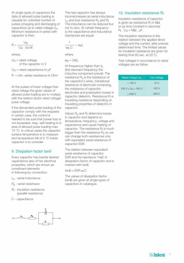
9. Disipation factor tanδEvery capacitor has beside desired capacitance also of her electrical properties, which are shown as constituent elements in following by connection:
Ls - serial inductance
Rs - serial resistnace
Ri - insulation resistance (parallel resistance)
C - capacitance
The real capacitor has always incorrectnesses as serial inductance Ls and loss resistance Rs and Ri. The inductance can be reduced but not to zero. At certain frequency f0 the capacitance and inductance reactances are equal:
1——— = ω0L ω0 C
where
ω0 = 2πf0
At frequencys higher than f0 (the resonant frequency) the inductive component prevail. The resistance Rs is the resistance of the capacitor’s wires, transitional resistance of electrode contacting, the resistance of capacitor electrodes and polarisation losses in capacitor dielectric. Resistance Ri is insulating resistance depending on insulating properties of dielectric in capacitor.
Values Rs and Ri determine losses in capacitor and depend on temperature, frequency, voltage and capacitance and cause heating of capacitor. The resistance Ri is much bigger then the resistance Rs so we can change both resistances only with equivalent serial resistance of capacitor ESR.
The relation between equivalent serial resistance of capacitor ESR and his reactance 1/ωC is dissipation factor of capacitor and is marked with tanδ.
tanδ = ESR.ω.C
The values of dissipation factor (tanδ) are given at single types of capacitors in catalogue.
10. Insulation resistance Ri
Insulation resistance of capacitor is given as resistance Ri in MΩ or as time constant in seconds Ri . CR = MΩ . μF.
The insulation resistance is the relation between the applied direct voltage and the current, after precise determined time. The limited values for insulation resistance are given for testing time 60 sec. at 20 ˚C.
Test voltages in accordance to rated voltages are as follow:
Rated voltage UR Test voltage
< 100 V 10 V
100 V ≤ UR < 500 V 100 V
≥ 500 V 500 V
10
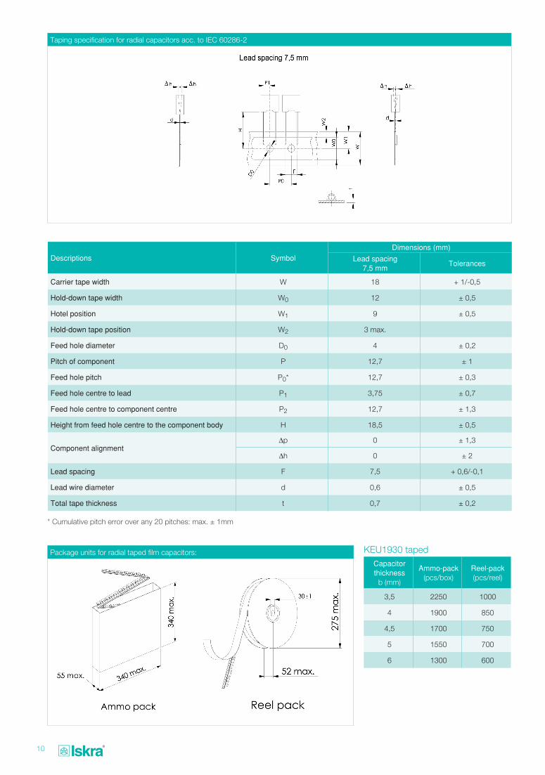
Descriptions SymbolDimensions (mm)
Lead spacing7,5 mm
Tolerances
Carrier tape width W 18 + 1/-0,5
Hold-down tape width W0 12 ± 0,5
Hotel position W1 9 ± 0,5
Hold-down tape position W2 3 max.
Feed hole diameter D0 4 ± 0,2
Pitch of component P 12,7 ± 1
Feed hole pitch P0* 12,7 ± 0,3
Feed hole centre to lead P1 3,75 ± 0,7
Feed hole centre to component centre P2 12,7 ± 1,3
Height from feed hole centre to the component body H 18,5 ± 0,5
Component alignment Δp 0 ± 1,3
Δh 0 ± 2
Lead spacing F 7,5 + 0,6/-0,1
Lead wire diameter d 0,6 ± 0,5
Total tape thickness t 0,7 ± 0,2
Capacitor thickness
b (mm)
Ammo-pack(pcs/box)
Reel-pack(pcs/reel)
3,5 2250 1000
4 1900 850
4,5 1700 750
5 1550 700
6 1300 600
* Cumulative pitch error over any 20 pitches: max. ± 1mm
Package units for radial taped film capacitors:
Taping specification for radial capacitors acc. to IEC 60286-2
KEU1930 taped
11
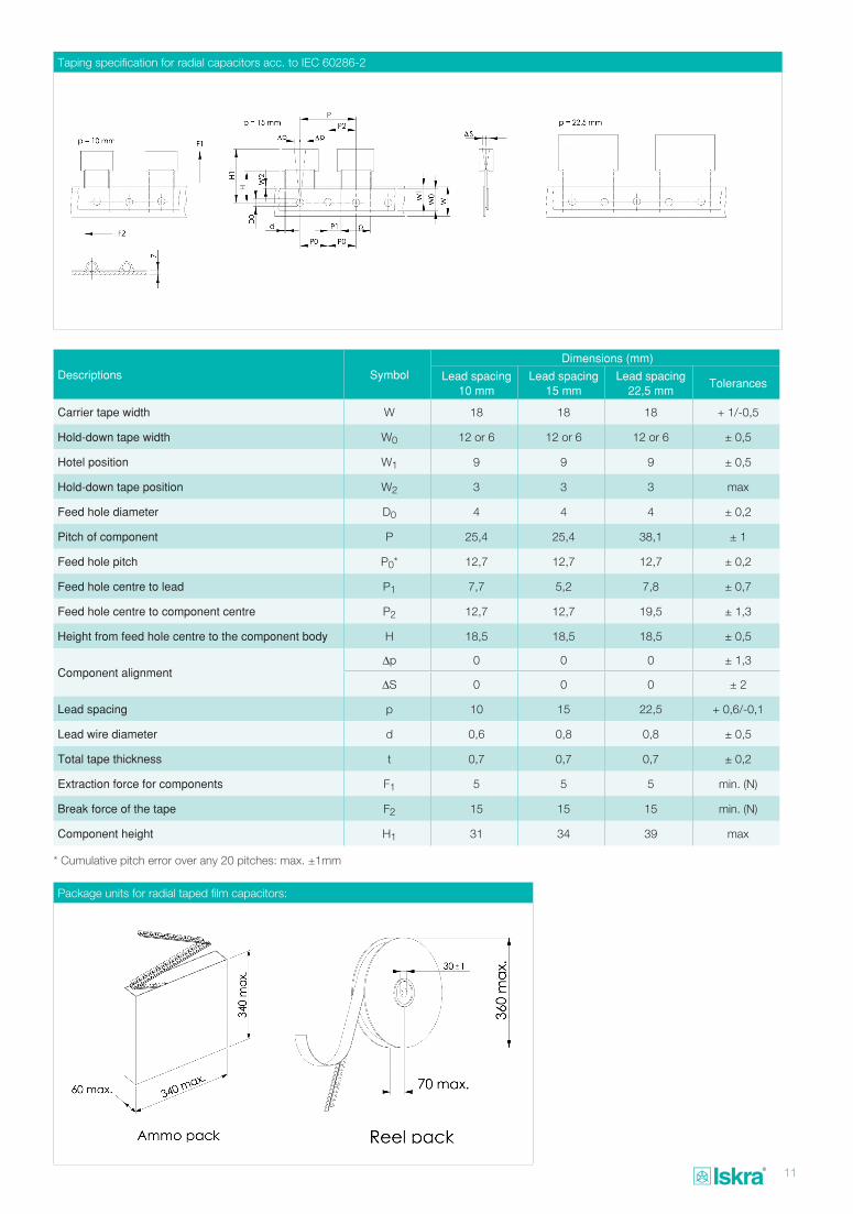
Descriptions SymbolDimensions (mm)
Lead spacing 10 mm
Lead spacing 15 mm
Lead spacing22,5 mm
Tolerances
Carrier tape width W 18 18 18 + 1/-0,5
Hold-down tape width W0 12 or 6 12 or 6 12 or 6 ± 0,5
Hotel position W1 9 9 9 ± 0,5
Hold-down tape position W2 3 3 3 max
Feed hole diameter D0 4 4 4 ± 0,2
Pitch of component P 25,4 25,4 38,1 ± 1
Feed hole pitch P0* 12,7 12,7 12,7 ± 0,2
Feed hole centre to lead P1 7,7 5,2 7,8 ± 0,7
Feed hole centre to component centre P2 12,7 12,7 19,5 ± 1,3
Height from feed hole centre to the component body H 18,5 18,5 18,5 ± 0,5
Component alignment Δp 0 0 0 ± 1,3
ΔS 0 0 0 ± 2
Lead spacing p 10 15 22,5 + 0,6/-0,1
Lead wire diameter d 0,6 0,8 0,8 ± 0,5
Total tape thickness t 0,7 0,7 0,7 ± 0,2
Extraction force for components F1 5 5 5 min. (N)
Break force of the tape F2 15 15 15 min. (N)
Component height H1 31 34 39 max
* Cumulative pitch error over any 20 pitches: max. ±1mm
Package units for radial taped film capacitors:
Taping specification for radial capacitors acc. to IEC 60286-2
12
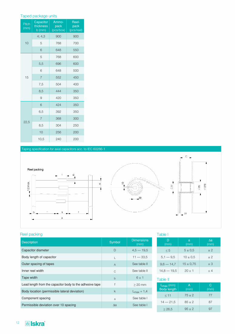
Pitch(mm)
Capacitor thickness
b (mm)
Ammo-pack
(pcs/box)
Reel-pack
(pcs/reel)
10
4; 4,3 900 900
5 768 700
6 648 550
15
5 768 600
5,5 696 600
6 648 500
7 552 450
7,5 504 400
8,5 444 350
9 420 350
22,5
6 424 350
6,5 392 350
7 368 300
8,5 304 250
10 256 200
10,5 240 200
Taped package units
Lmax (mm)Body length
A(mm)
C(mm)
≤ 11 75 ± 2 77
14 — 21,5 85 ± 2 87
≥ 26,5 95 ± 2 97
Table II
D(mm)
a(mm)
Δa(mm)
≤ 5 5 ± 0,5 ± 2
5,1 — 9,5 10 ± 0,5 ± 2
9,6 — 14,7 15 ± 0,75 ± 3
14,8 — 19,5 20 ± 1 ± 4
Table I
Taping specification for axial capacitors acc. to IEC 60286-1
Reel packing
Description SymbolDimensions
(mm)
Capacitor diameter D 4,5 — 19,5
Body length of capacitor L 11 — 33,5
Outer spacing of tapes A See table II
Inner reel width C See table II
Tape width b 6 ± 1
Lead length from the capacitor body to the adhesive tape f ≥ 20 mm
Body location (permissible lateral deviation) k Lmax + 1,4
Component spacing a See table I
Permissible deviation over 10 spacing Δa See table I
13
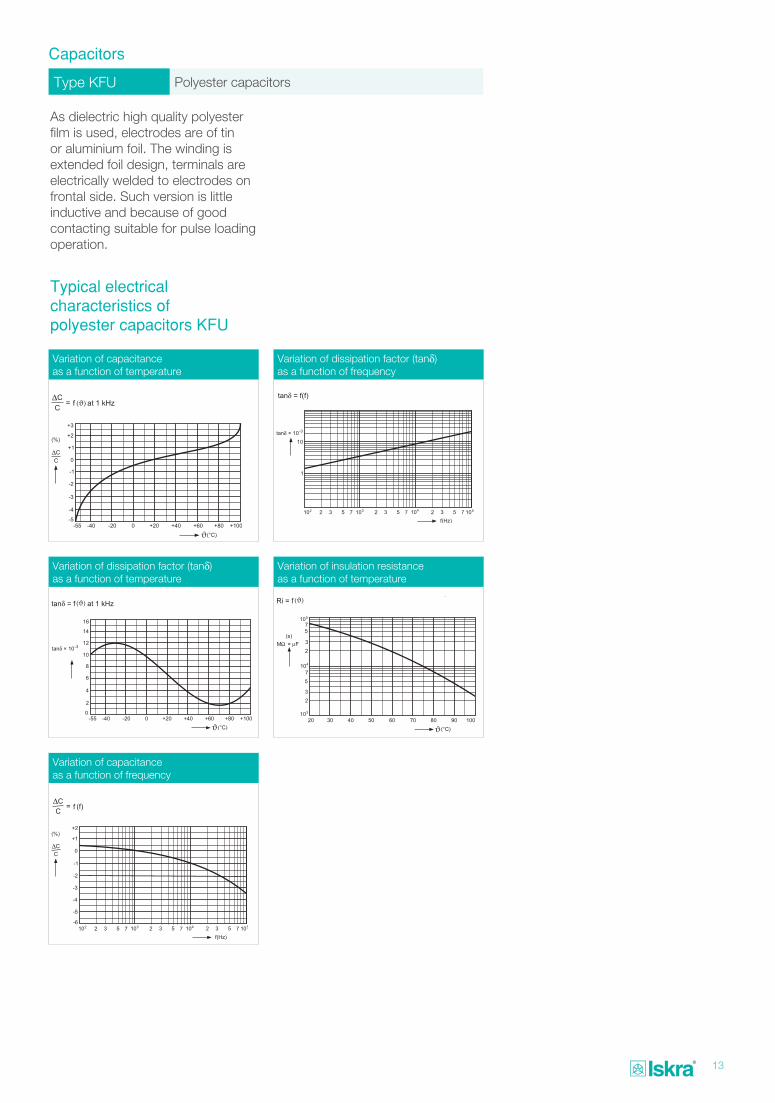
Type KFU Polyester capacitors
Capacitors
As dielectric high quality polyester film is used, electrodes are of tin or aluminium foil. The winding is extended foil design, terminals are electrically welded to electrodes on frontal side. Such version is little inductive and because of good contacting suitable for pulse loading operation.
Typical electrical characteristics of polyester capacitors KFU
Variation of capacitance as a function of temperature
Variation of dissipation factor (tanδ) as a function of temperature
Variation of capacitance as a function of frequency
Variation of dissipation factor (tanδ) as a function of frequency
Variation of insulation resistance as a function of temperature
ϑ
ϑ ϑ
14
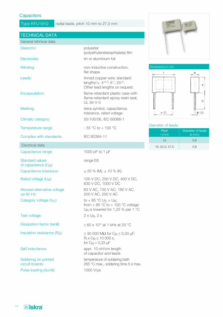
Type KFU1910 radial leads, pitch 10 mm to 27,5 mm
Capacitors
TECHNICAL DATA
General tehnical data
Dielectric: polyester (polyethyleneterephtalate) film
Electrodes: tin or aluminium foil
Winding: non-inductive construction, flat shape
Leads: tinned copper wire; standard lengths l1: 4±0,5; 6-1; 25±5. Other lead lengths on request.
Encapsulation: flame-retardant plastic case with flame-retardant epoxy resin seal, UL 94 V-0
Marking: Iskra symbol, capacitance, tolerance, rated voltage
Climatic category: 55/100/56, IEC 60068-1
Temperature range: - 55 °C to + 100 °C
Complies with standards: IEC 60384-11
Electrical data
Capacitance range: 1000 pF to 1 μF
Standard values of capacitance (CR):
range E6
Capacitance tolerance: ± 20 % (M), ± 10 % (K)
Rated voltage (UR): 100 V DC, 250 V DC, 400 V DC, 630 V DC, 1000 V DC
Allowed alternative voltage up 60 Hz:
63 V AC, 100 V AC, 160 V AC, 200 V AC, 250 V AC
Category voltage (UC): to + 85 °C UC = UR; from + 85 °C to + 100 °C voltage UR is lowered for 1,25 % per 1 °C
Test voltage: 2 x UR, 2 s
Dissipation factor (tanδ): ≤ 60 x 10-4 at 1 kHz at 20 °C
Insulation resistance (RR): ≥ 30 000 MΩ for CR ≤ 0,33 μF; Ri x CR ≥ 10 000 s, for CR > 0,33 μF
Self inductance: appr. 10 nH/cm length of capacitor and leads
Soldering on printed circuit boards:
temperature of soldering bath 265 °C max., soldering time 5 s max.
Pulse loading (du/dt): 1000 V/μs
Dimensions in mm
Pitchr (mm)
Diameter of leadsø (mm)
10 0,6
15; 22,5; 27,5 0,8
Diameter of leads:
15
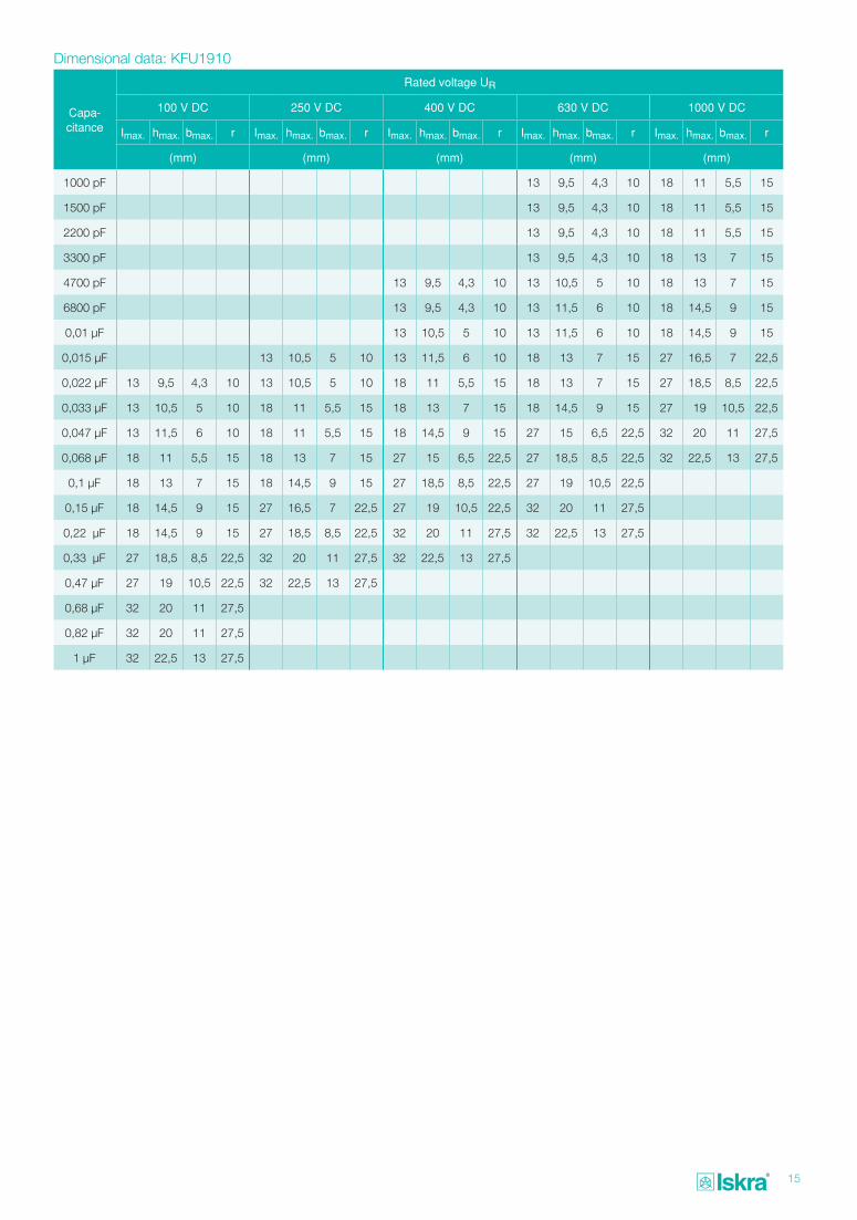
Capa- citance
Rated voltage UR
100 V DC 250 V DC 400 V DC 630 V DC 1000 V DC
Imax. hmax. bmax. r Imax. hmax. bmax. r Imax. hmax. bmax. r Imax. hmax. bmax. r Imax. hmax. bmax. r
(mm) (mm) (mm) (mm) (mm)
1000 pF 13 9,5 4,3 10 18 11 5,5 15
1500 pF 13 9,5 4,3 10 18 11 5,5 15
2200 pF 13 9,5 4,3 10 18 11 5,5 15
3300 pF 13 9,5 4,3 10 18 13 7 15
4700 pF 13 9,5 4,3 10 13 10,5 5 10 18 13 7 15
6800 pF 13 9,5 4,3 10 13 11,5 6 10 18 14,5 9 15
0,01 μF 13 10,5 5 10 13 11,5 6 10 18 14,5 9 15
0,015 μF 13 10,5 5 10 13 11,5 6 10 18 13 7 15 27 16,5 7 22,5
0,022 μF 13 9,5 4,3 10 13 10,5 5 10 18 11 5,5 15 18 13 7 15 27 18,5 8,5 22,5
0,033 μF 13 10,5 5 10 18 11 5,5 15 18 13 7 15 18 14,5 9 15 27 19 10,5 22,5
0,047 μF 13 11,5 6 10 18 11 5,5 15 18 14,5 9 15 27 15 6,5 22,5 32 20 11 27,5
0,068 μF 18 11 5,5 15 18 13 7 15 27 15 6,5 22,5 27 18,5 8,5 22,5 32 22,5 13 27,5
0,1 μF 18 13 7 15 18 14,5 9 15 27 18,5 8,5 22,5 27 19 10,5 22,5
0,15 μF 18 14,5 9 15 27 16,5 7 22,5 27 19 10,5 22,5 32 20 11 27,5
0,22 μF 18 14,5 9 15 27 18,5 8,5 22,5 32 20 11 27,5 32 22,5 13 27,5
0,33 μF 27 18,5 8,5 22,5 32 20 11 27,5 32 22,5 13 27,5
0,47 μF 27 19 10,5 22,5 32 22,5 13 27,5
0,68 μF 32 20 11 27,5
0,82 μF 32 20 11 27,5
1 μF 32 22,5 13 27,5
Dimensional data: KFU1910
16
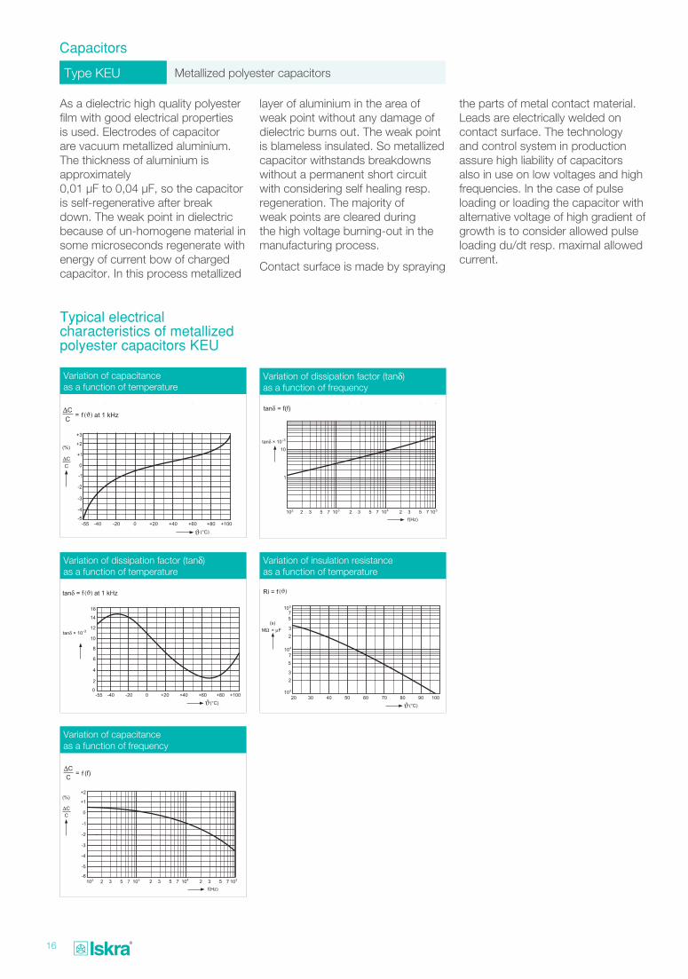
Type KEU Metallized polyester capacitors
Capacitors
As a dielectric high quality polyester film with good electrical properties is used. Electrodes of capacitor are vacuum metallized aluminium. The thickness of aluminium is approximately 0,01 μF to 0,04 μF, so the capacitor is self-regenerative after break down. The weak point in dielectric because of un-homogene material in some microseconds regenerate with energy of current bow of charged capacitor. In this process metallized
Typical electrical characteristics of metallized polyester capacitors KEU
layer of aluminium in the area of weak point without any damage of dielectric burns out. The weak point is blameless insulated. So metallized capacitor withstands breakdowns without a permanent short circuit with considering self healing resp. regeneration. The majority of weak points are cleared during the high voltage burning-out in the manufacturing process.
Contact surface is made by spraying
the parts of metal contact material. Leads are electrically welded on contact surface. The technology and control system in production assure high liability of capacitors also in use on low voltages and high frequencies. In the case of pulse loading or loading the capacitor with alternative voltage of high gradient of growth is to consider allowed pulse loading du/dt resp. maximal allowed current.
Variation of dissipation factor (tanδ) as a function of frequency
Variation of capacitance as a function of temperature
ϑ
Variation of dissipation factor (tanδ) as a function of temperature
ϑ
Variation of capacitance as a function of frequency
Variation of insulation resistance as a function of temperature
ϑ
17
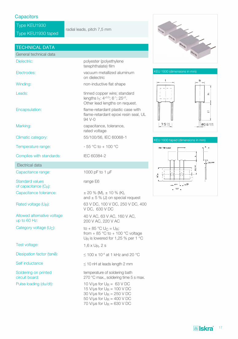
Type KEU1930radial leads, pitch 7,5 mm
Type KEU1930 taped
Capacitors
TECHNICAL DATA
General technical data
Dielectric: polyester (polyethylene terephthalate) film
Electrodes: vacuum metallized aluminum on dielectric
Winding: non-inductive flat shape
Leads: tinned copper wire; standard lengths l1: 4±0,5; 6-1; 25±5. Other lead lengths on request.
Encapsulation: flame-retardant plastic case with flame-retardant epoxi resin seal, UL 94 V-0
Marking: capacitance, tolerance, rated voltage
Climatic category: 55/100/56, IEC 60068-1
Temperature range: - 55 °C to + 100 °C
Complies with standards: IEC 60384-2
Electrical data
Capacitance range: 1000 pF to 1 μF
Standard values of capacitance (CR):
range E6
Capacitance tolerance: ± 20 % (M), ± 10 % (K), and ± 5 % (J) on special request
Rated voltage (UR): 63 V DC, 100 V DC, 250 V DC, 400 V DC, 630 V DC
Allowed alternative voltage up to 60 Hz:
40 V AC, 63 V AC, 160 V AC, 200 V AC, 220 V AC
Category voltage (UC): to + 85 °C UC = UR; from + 85 °C to + 100 °C voltage UR is lowered for 1,25 % per 1 °C
Test voltage: 1,6 x UR, 2 s
Dissipation factor (tanδ): ≤ 100 x 10-4 at 1 kHz and 20 °C
Self inductance ≤ 10 nH at leads length 2 mm
Soldering on printed circuit board:
temperature of soldering bath 270 °C max., soldering time 5 s max.
Pulse loading (du/dt): 10 V/μs for UR = 63 V DC15 V/μs for UR = 100 V DC30 V/μs for UR = 250 V DC50 V/μs for UR = 400 V DC70 V/μs for UR = 630 V DC
KEU 1930 (dimensions in mm)
KEU 1930 taped (dimensions in mm)
18
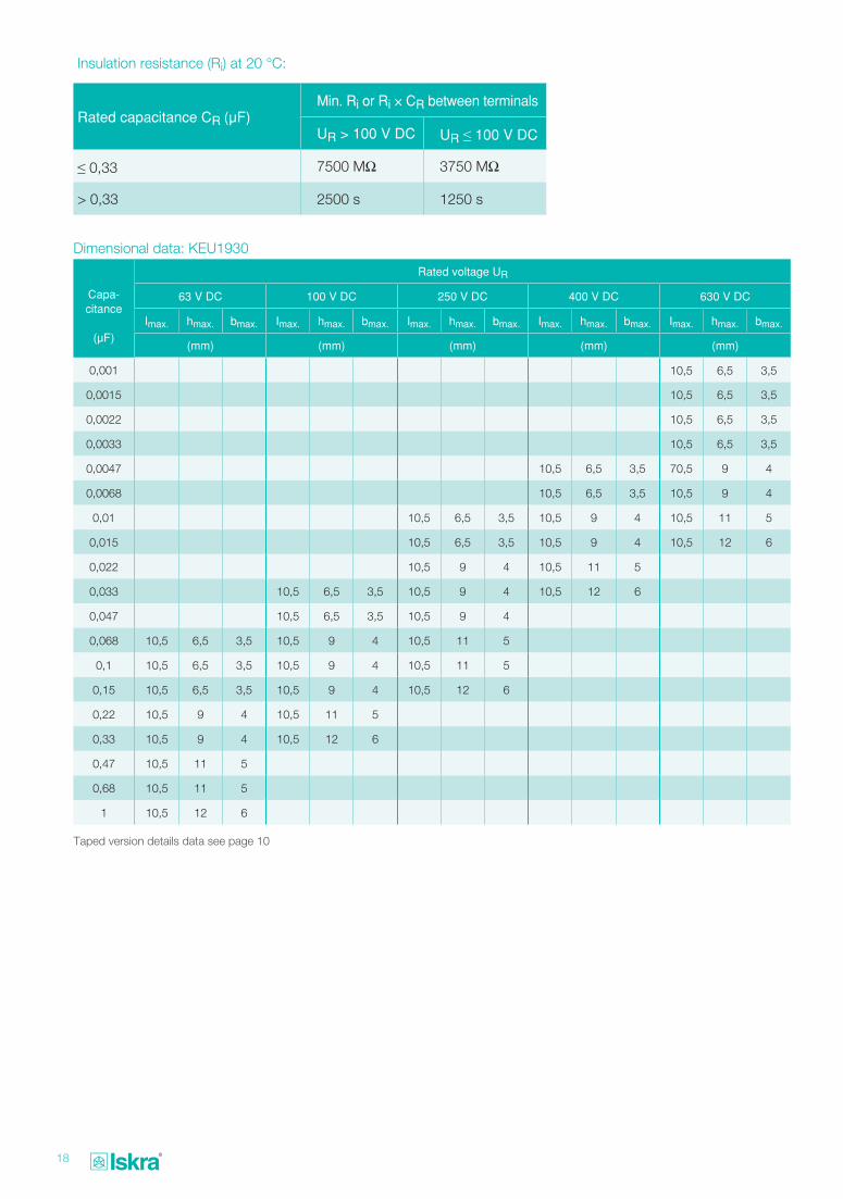
Insulation resistance (Ri) at 20 °C:
Rated capacitance CR (μF)Min. Ri or Ri × CR between terminals
UR > 100 V DC UR ≤ 100 V DC
≤ 0,33 7500 MΩ 3750 MΩ
> 0,33 2500 s 1250 s
Capa- citance
(μF)
Rated voltage UR
63 V DC 100 V DC 250 V DC 400 V DC 630 V DC
Imax. hmax. bmax. Imax. hmax. bmax. Imax. hmax. bmax. Imax. hmax. bmax. Imax. hmax. bmax.
(mm) (mm) (mm) (mm) (mm)
0,001 10,5 6,5 3,5
0,0015 10,5 6,5 3,5
0,0022 10,5 6,5 3,5
0,0033 10,5 6,5 3,5
0,0047 10,5 6,5 3,5 70,5 9 4
0,0068 10,5 6,5 3,5 10,5 9 4
0,01 10,5 6,5 3,5 10,5 9 4 10,5 11 5
0,015 10,5 6,5 3,5 10,5 9 4 10,5 12 6
0,022 10,5 9 4 10,5 11 5
0,033 10,5 6,5 3,5 10,5 9 4 10,5 12 6
0,047 10,5 6,5 3,5 10,5 9 4
0,068 10,5 6,5 3,5 10,5 9 4 10,5 11 5
0,1 10,5 6,5 3,5 10,5 9 4 10,5 11 5
0,15 10,5 6,5 3,5 10,5 9 4 10,5 12 6
0,22 10,5 9 4 10,5 11 5
0,33 10,5 9 4 10,5 12 6
0,47 10,5 11 5
0,68 10,5 11 5
1 10,5 12 6
Dimensional data: KEU1930
Taped version details data see page 10
19
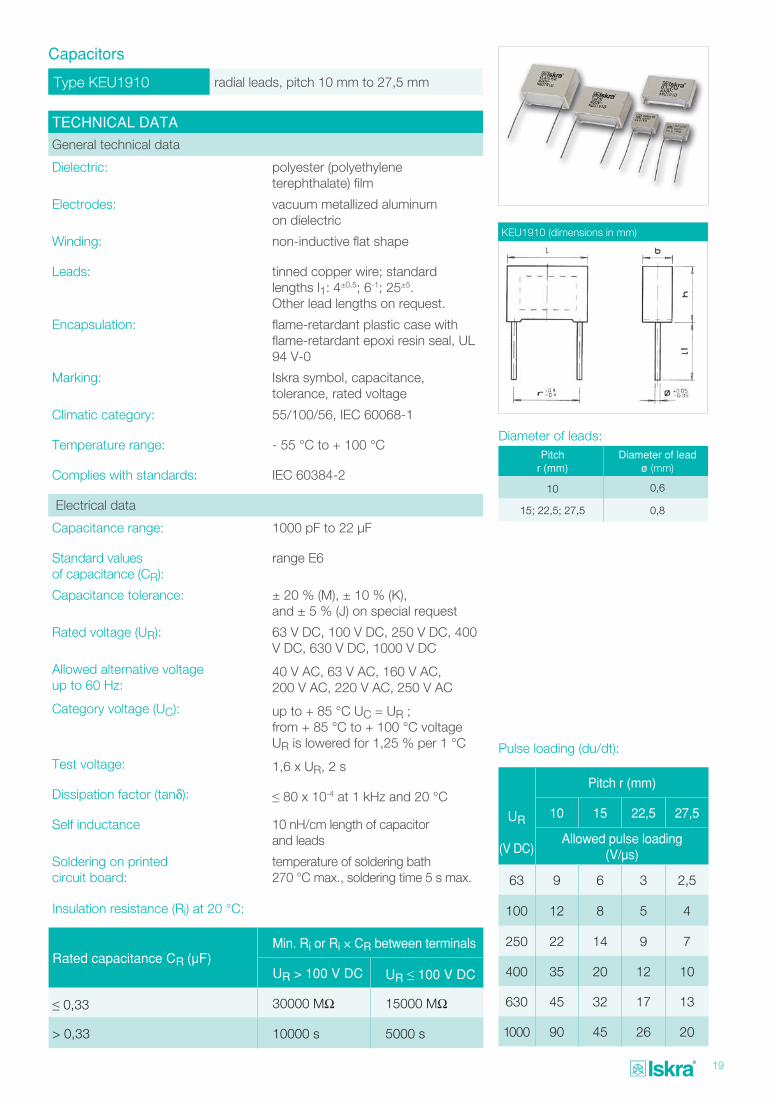
Type KEU1910 radial leads, pitch 10 mm to 27,5 mm
Capacitors
TECHNICAL DATA
General technical data
Dielectric: polyester (polyethylene terephthalate) film
Electrodes: vacuum metallized aluminum on dielectric
Winding: non-inductive flat shape
Leads: tinned copper wire; standard lengths l1: 4±0,5; 6-1; 25±5. Other lead lengths on request.
Encapsulation: flame-retardant plastic case with flame-retardant epoxi resin seal, UL 94 V-0
Marking: Iskra symbol, capacitance, tolerance, rated voltage
Climatic category: 55/100/56, IEC 60068-1
Temperature range: - 55 °C to + 100 °C
Complies with standards: IEC 60384-2
Electrical data
Capacitance range: 1000 pF to 22 μF
Standard values of capacitance (CR):
range E6
Capacitance tolerance: ± 20 % (M), ± 10 % (K), and ± 5 % (J) on special request
Rated voltage (UR): 63 V DC, 100 V DC, 250 V DC, 400 V DC, 630 V DC, 1000 V DC
Allowed alternative voltage up to 60 Hz:
40 V AC, 63 V AC, 160 V AC, 200 V AC, 220 V AC, 250 V AC
Category voltage (UC): up to + 85 °C UC = UR ; from + 85 °C to + 100 °C voltage UR is lowered for 1,25 % per 1 °C
Test voltage: 1,6 x UR, 2 s
Dissipation factor (tanδ): ≤ 80 x 10-4 at 1 kHz and 20 °C
Self inductance 10 nH/cm length of capacitor and leads
Soldering on printed circuit board:
temperature of soldering bath 270 °C max., soldering time 5 s max.
KEU1910 (dimensions in mm)
Insulation resistance (Ri) at 20 °C:
Rated capacitance CR (μF)Min. Ri or Ri × CR between terminals
UR > 100 V DC UR ≤ 100 V DC
≤ 0,33 30000 MΩ 15000 MΩ
> 0,33 10000 s 5000 s
Pulse loading (du/dt):
UR
(V DC)
Pitch r (mm)
10 15 22,5 27,5
Allowed pulse loading (V/μs)
63 9 6 3 2,5
100 12 8 5 4
250 22 14 9 7
400 35 20 12 10
630 45 32 17 13
1000 90 45 26 20
Pitch r (mm)
Diameter of lead ø (mm)
10 0,6
15; 22,5; 27,5 0,8
Diameter of leads:
20
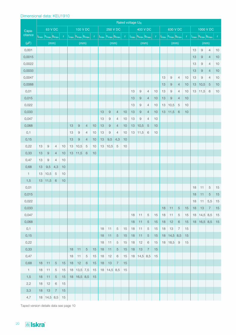
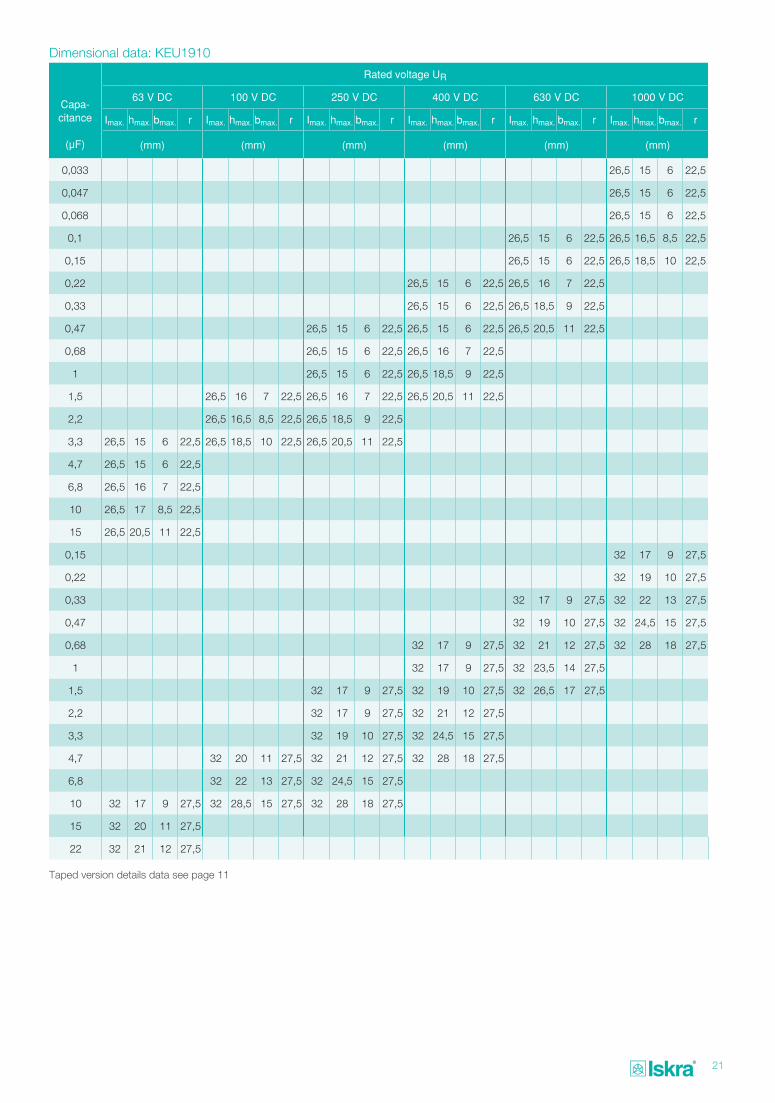
Dimensional data: KEU1910
Taped version details data see page 10
Capa- citance
(μF)
Rated voltage UR
63 V DC 100 V DC 250 V DC 400 V DC 630 V DC 1000 V DC
Imax. hmax. bmax. r Imax. hmax. bmax. r Imax. hmax. bmax. r Imax. hmax. bmax. r Imax. hmax. bmax. r Imax. hmax. bmax. r
(mm) (mm) (mm) (mm) (mm) (mm)
0,001 13 9 4 10
0,0015 13 9 4 10
0,0022 13 9 4 10
0,0033 13 9 4 10
0,0047 13 9 4 10 13 9 4 10
0,0068 13 9 4 10 13 10,5 5 10
0,01 13 9 4 10 13 9 4 10 13 11,5 6 10
0,015 13 9 4 10 13 9 4 10
0,022 13 9 4 10 13 10,5 5 10
0,033 13 9 4 10 13 9 4 10 13 11,5 6 10
0,047 13 9 4 10 13 9 4 10
0,068 13 9 4 10 13 9 4 10 13 10,5 5 10
0,1 13 9 4 10 13 9 4 10 13 11,5 6 10
0,15 13 9 4 10 13 9,5 4,3 10
0,22 13 9 4 10 13 10,5 5 10 13 10,5 5 10
0,33 13 9 4 10 13 11,5 6 10
0,47 13 9 4 10
0,68 13 9,5 4,3 10
1 13 10,5 5 10
1,5 13 11,5 6 10
0,01 18 11 5 15
0,015 18 11 5 15
0,022 18 11 5,5 15
0,033 18 11 5 15 18 13 7 15
0,047 18 11 5 15 18 11 5 15 18 14,5 8,5 15
0,068 18 11 5 15 18 12 6 15 18 16,5 8,5 15
0,1 18 11 5 15 18 11 5 15 18 13 7 15
0,15 18 11 5 15 18 11 5 15 18 14,5 8,5 15
0,22 18 11 5 15 18 12 6 15 18 18,5 9 15
0,33 18 11 5 15 18 11 5 15 18 13 7 15
0,47 18 11 5 15 18 12 6 15 18 14,5 8,5 15
0,68 18 11 5 15 18 12 6 15 18 13 7 15
1 18 11 5 15 18 13,5 7,5 15 18 14,5 8,5 15
1,5 18 11 5 15 18 16,5 8,5 15
2,2 18 12 6 15
3,3 18 13 7 15
4,7 18 14,5 8,5 15
21
Dimensional data: KEU1910
Capa- citance
(μF)
Rated voltage UR
63 V DC 100 V DC 250 V DC 400 V DC 630 V DC 1000 V DC
Imax. hmax. bmax. r Imax. hmax. bmax. r Imax. hmax. bmax. r Imax. hmax. bmax. r Imax. hmax. bmax. r Imax. hmax. bmax. r
(mm) (mm) (mm) (mm) (mm) (mm)
0,033 26,5 15 6 22,5
0,047 26,5 15 6 22,5
0,068 26,5 15 6 22,5
0,1 26,5 15 6 22,5 26,5 16,5 8,5 22,5
0,15 26,5 15 6 22,5 26,5 18,5 10 22,5
0,22 26,5 15 6 22,5 26,5 16 7 22,5
0,33 26,5 15 6 22,5 26,5 18,5 9 22,5
0,47 26,5 15 6 22,5 26,5 15 6 22,5 26,5 20,5 11 22,5
0,68 26,5 15 6 22,5 26,5 16 7 22,5
1 26,5 15 6 22,5 26,5 18,5 9 22,5
1,5 26,5 16 7 22,5 26,5 16 7 22,5 26,5 20,5 11 22,5
2,2 26,5 16,5 8,5 22,5 26,5 18,5 9 22,5
3,3 26,5 15 6 22,5 26,5 18,5 10 22,5 26,5 20,5 11 22,5
4,7 26,5 15 6 22,5
6,8 26,5 16 7 22,5
10 26,5 17 8,5 22,5
15 26,5 20,5 11 22,5
0,15 32 17 9 27,5
0,22 32 19 10 27,5
0,33 32 17 9 27,5 32 22 13 27,5
0,47 32 19 10 27,5 32 24,5 15 27,5
0,68 32 17 9 27,5 32 21 12 27,5 32 28 18 27,5
1 32 17 9 27,5 32 23,5 14 27,5
1,5 32 17 9 27,5 32 19 10 27,5 32 26,5 17 27,5
2,2 32 17 9 27,5 32 21 12 27,5
3,3 32 19 10 27,5 32 24,5 15 27,5
4,7 32 20 11 27,5 32 21 12 27,5 32 28 18 27,5
6,8 32 22 13 27,5 32 24,5 15 27,5
10 32 17 9 27,5 32 28,5 15 27,5 32 28 18 27,5
15 32 20 11 27,5
22 32 21 12 27,5
Taped version details data see page 11
22
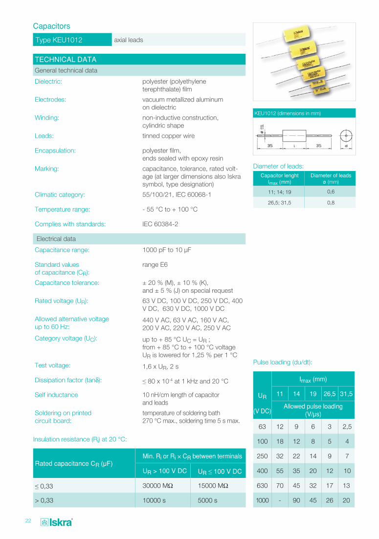
Type KEU1012 axial leads
Capacitors
TECHNICAL DATA
General technical data
Dielectric: polyester (polyethylene terephthalate) film
Electrodes: vacuum metallized aluminum on dielectric
Winding: non-inductive construction, cylindric shape
Leads: tinned copper wire
Encapsulation: polyester film, ends sealed with epoxy resin
Marking: capacitance, tolerance, rated volt-age (at larger dimensions also Iskra symbol, type designation)
Climatic category: 55/100/21, IEC 60068-1
Temperature range: - 55 °C to + 100 °C
Complies with standards: IEC 60384-2
Electrical data
Capacitance range: 1000 pF to 10 μF
Standard values of capacitance (CR):
range E6
Capacitance tolerance: ± 20 % (M), ± 10 % (K), and ± 5 % (J) on special request
Rated voltage (UR): 63 V DC, 100 V DC, 250 V DC, 400 V DC, 630 V DC, 1000 V DC
Allowed alternative voltage up to 60 Hz:
440 V AC, 63 V AC, 160 V AC, 200 V AC, 220 V AC, 250 V AC
Category voltage (UC): up to + 85 °C UC = UR ; from + 85 °C to + 100 °C voltage UR is lowered for 1,25 % per 1 °C
Test voltage: 1,6 x UR, 2 s
Dissipation factor (tanδ): ≤ 80 x 10-4 at 1 kHz and 20 °C
Self inductance 10 nH/cm length of capacitor and leads
Soldering on printed circuit board:
temperature of soldering bath 270 °C max., soldering time 5 s max.
KEU1012 (dimensions in mm)
Insulation resistance (Ri) at 20 °C:
Rated capacitance CR (μF)Min. Ri or Ri × CR between terminals
UR > 100 V DC UR ≤ 100 V DC
≤ 0,33 30000 MΩ 15000 MΩ
> 0,33 10000 s 5000 s
Pulse loading (du/dt):
UR
(V DC)
Imax (mm)
11 14 19 26,5 31,5
Allowed pulse loading (V/μs)
63 12 9 6 3 2,5
100 18 12 8 5 4
250 32 22 14 9 7
400 55 35 20 12 10
630 70 45 32 17 13
1000 - 90 45 26 20
Capacitor lenghtImax (mm)
Diameter of leads ø (mm)
11; 14; 19 0,6
26,5; 31,5 0,8
Diameter of leads:
23
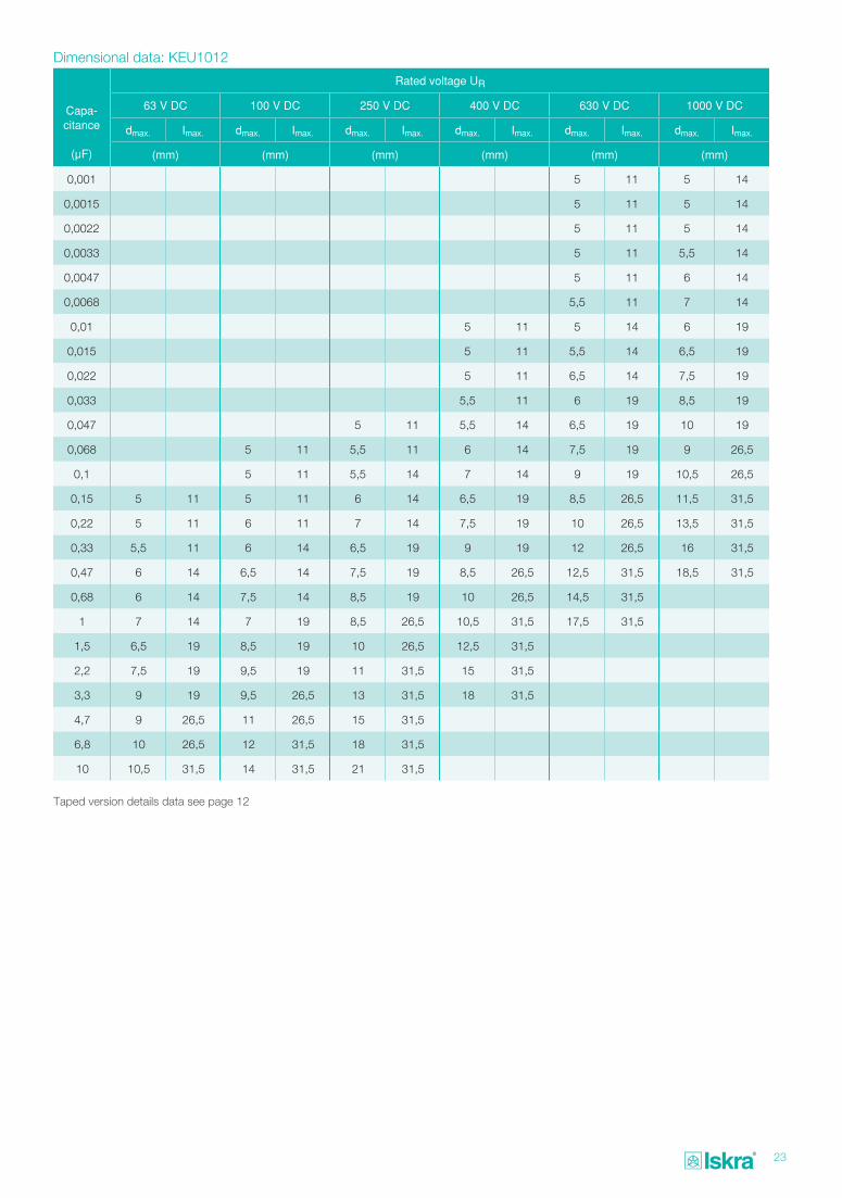
Dimensional data: KEU1012
Capa- citance
(μF)
Rated voltage UR
63 V DC 100 V DC 250 V DC 400 V DC 630 V DC 1000 V DC
dmax. Imax. dmax. Imax. dmax. Imax. dmax. Imax. dmax. Imax. dmax. Imax.
(mm) (mm) (mm) (mm) (mm) (mm)
0,001 5 11 5 14
0,0015 5 11 5 14
0,0022 5 11 5 14
0,0033 5 11 5,5 14
0,0047 5 11 6 14
0,0068 5,5 11 7 14
0,01 5 11 5 14 6 19
0,015 5 11 5,5 14 6,5 19
0,022 5 11 6,5 14 7,5 19
0,033 5,5 11 6 19 8,5 19
0,047 5 11 5,5 14 6,5 19 10 19
0,068 5 11 5,5 11 6 14 7,5 19 9 26,5
0,1 5 11 5,5 14 7 14 9 19 10,5 26,5
0,15 5 11 5 11 6 14 6,5 19 8,5 26,5 11,5 31,5
0,22 5 11 6 11 7 14 7,5 19 10 26,5 13,5 31,5
0,33 5,5 11 6 14 6,5 19 9 19 12 26,5 16 31,5
0,47 6 14 6,5 14 7,5 19 8,5 26,5 12,5 31,5 18,5 31,5
0,68 6 14 7,5 14 8,5 19 10 26,5 14,5 31,5
1 7 14 7 19 8,5 26,5 10,5 31,5 17,5 31,5
1,5 6,5 19 8,5 19 10 26,5 12,5 31,5
2,2 7,5 19 9,5 19 11 31,5 15 31,5
3,3 9 19 9,5 26,5 13 31,5 18 31,5
4,7 9 26,5 11 26,5 15 31,5
6,8 10 26,5 12 31,5 18 31,5
10 10,5 31,5 14 31,5 21 31,5
Taped version details data see page 12
24
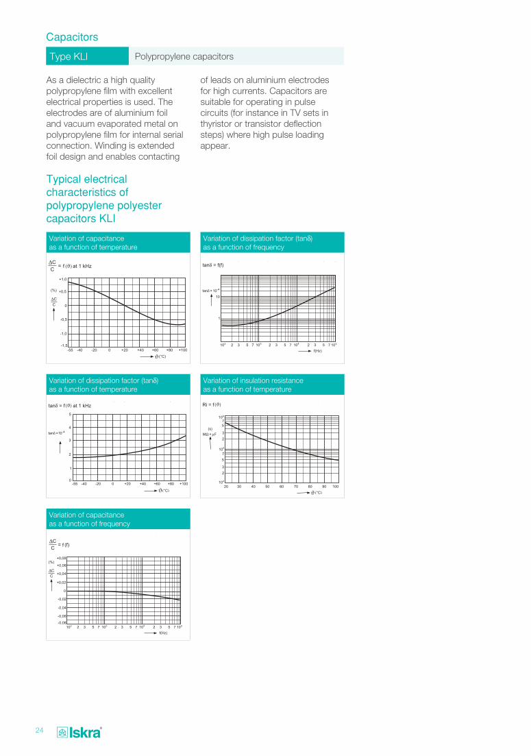
Type KLI Polypropylene capacitors
Capacitors
As a dielectric a high quality polypropylene film with excellent electrical properties is used. The electrodes are of aluminium foil and vacuum evaporated metal on polypropylene film for internal serial connection. Winding is extended foil design and enables contacting
Typical electrical characteristics of polypropylene polyester capacitors KLI
of leads on aluminium electrodes for high currents. Capacitors are suitable for operating in pulse circuits (for instance in TV sets in thyristor or transistor deflection steps) where high pulse loading appear.
Variation of capacitance as a function of temperature
Variation of dissipation factor (tanδ) as a function of temperature
Variation of capacitance as a function of frequency
Variation of dissipation factor (tanδ) as a function of frequency
Variation of insulation resistance as a function of temperature
ϑϑ
ϑ
25
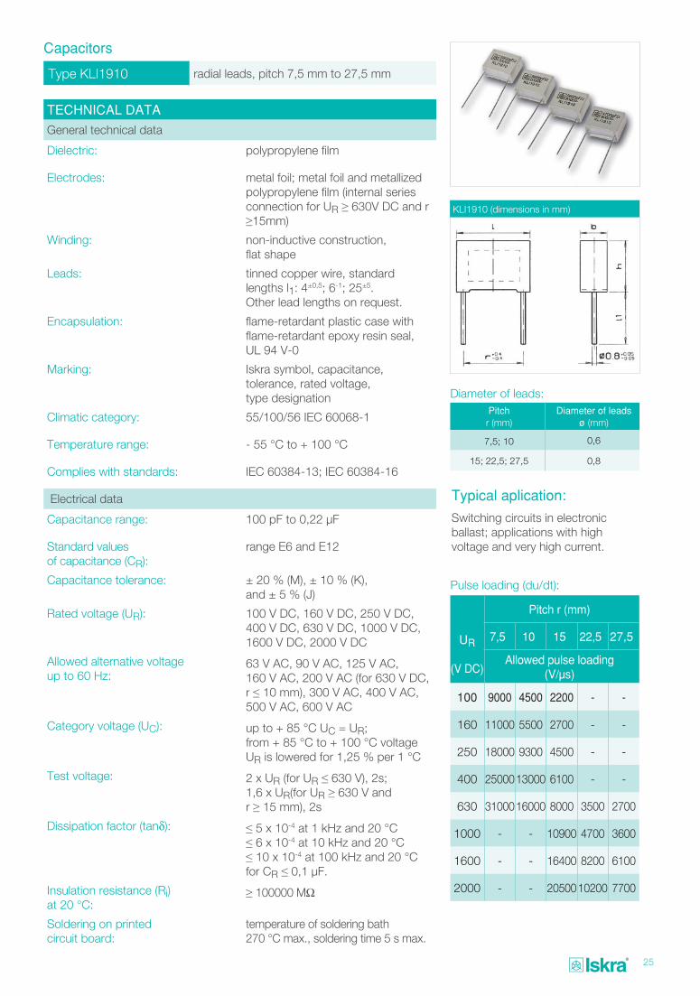
Type KLI1910 radial leads, pitch 7,5 mm to 27,5 mm
Capacitors
TECHNICAL DATA
General technical data
Dielectric: polypropylene film
Electrodes: metal foil; metal foil and metallized polypropylene film (internal series connection for UR ≥ 630V DC and r ≥15mm)
Winding: non-inductive construction, flat shape
Leads: tinned copper wire, standard lengths l1: 4±0,5; 6-1; 25±5. Other lead lengths on request.
Encapsulation: flame-retardant plastic case with flame-retardant epoxy resin seal, UL 94 V-0
Marking: Iskra symbol, capacitance, tolerance, rated voltage, type designation
Climatic category: 55/100/56 IEC 60068-1
Temperature range: - 55 °C to + 100 °C
Complies with standards: IEC 60384-13; IEC 60384-16
Electrical data
Capacitance range: 100 pF to 0,22 μF
Standard values of capacitance (CR):
range E6 and E12
Capacitance tolerance: ± 20 % (M), ± 10 % (K), and ± 5 % (J)
Rated voltage (UR): 100 V DC, 160 V DC, 250 V DC, 400 V DC, 630 V DC, 1000 V DC, 1600 V DC, 2000 V DC
Allowed alternative voltage up to 60 Hz:
63 V AC, 90 V AC, 125 V AC, 160 V AC, 200 V AC (for 630 V DC, r ≤ 10 mm), 300 V AC, 400 V AC, 500 V AC, 600 V AC
Category voltage (UC): up to + 85 °C UC = UR; from + 85 °C to + 100 °C voltage UR is lowered for 1,25 % per 1 °C
Test voltage: 2 x UR (for UR ≤ 630 V), 2s;1,6 x UR(for UR ≥ 630 V and r ≥ 15 mm), 2s
Dissipation factor (tanδ): ≤ 5 x 10⁻⁴ at 1 kHz and 20 °C≤ 6 x 10⁻⁴ at 10 kHz and 20 °C≤ 10 x 10-4 at 100 kHz and 20 °C for CR ≤ 0,1 μF.
Insulation resistance (Ri) at 20 °C:
≥ 100000 MΩ
Soldering on printed circuit board:
temperature of soldering bath 270 °C max., soldering time 5 s max.
KLI1910 (dimensions in mm)
Pulse loading (du/dt):
UR
(V DC)
Pitch r (mm)
7,5 10 15 22,5 27,5
Allowed pulse loading (V/μs)
100 9000 4500 2200 - -
160 11000 5500 2700 - -
250 18000 9300 4500 - -
400 2500013000 6100 - -
630 3100016000 8000 3500 2700
1000 - - 10900 4700 3600
1600 - - 16400 8200 6100
2000 - - 2050010200 7700
Pitch r (mm)
Diameter of leads ø (mm)
7,5; 10 0,6
15; 22,5; 27,5 0,8
Diameter of leads:
Typical aplication:
Switching circuits in electronic ballast; applications with high voltage and very high current.
26
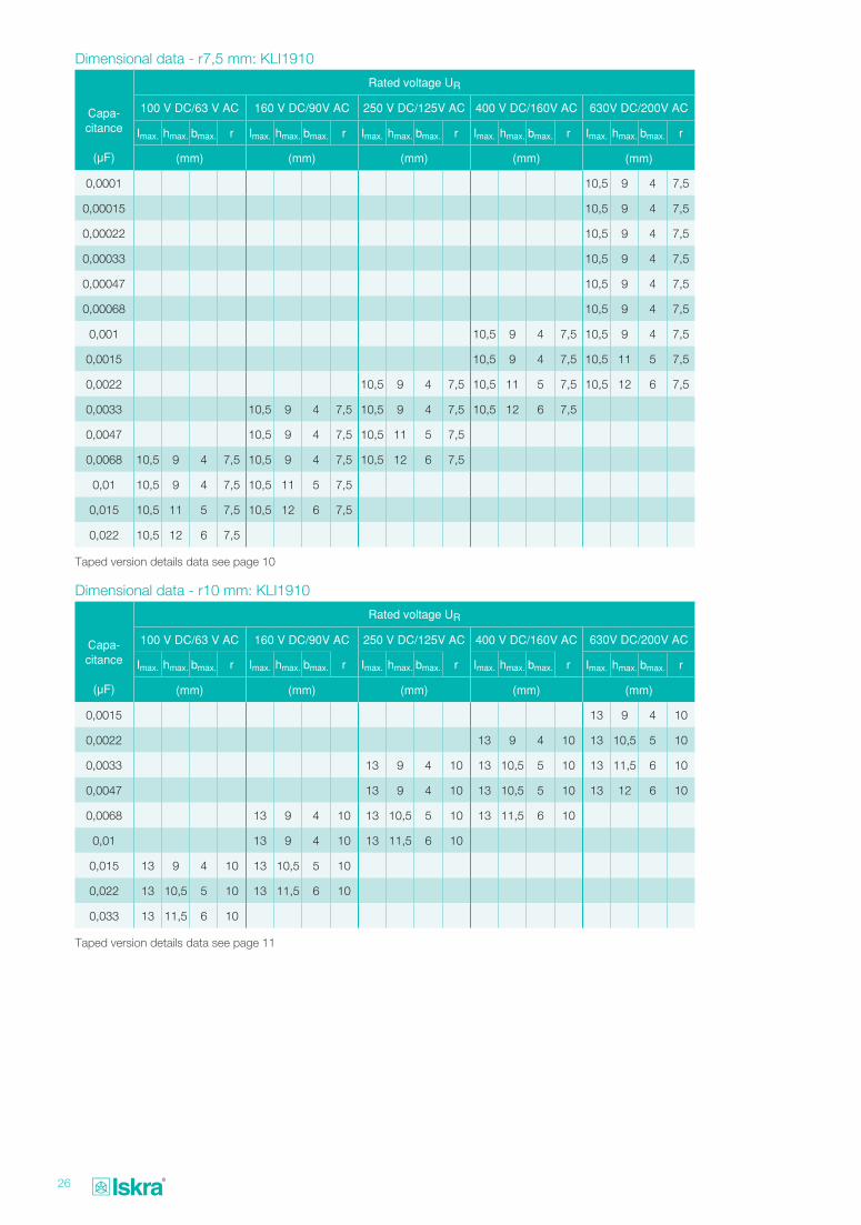
Dimensional data - r7,5 mm: KLI1910
Dimensional data - r10 mm: KLI1910
Capa- citance
(μF)
Rated voltage UR
100 V DC/63 V AC 160 V DC/90V AC 250 V DC/125V AC 400 V DC/160V AC 630V DC/200V AC
Imax. hmax. bmax. r Imax. hmax. bmax. r Imax. hmax. bmax. r Imax. hmax. bmax. r Imax. hmax. bmax. r
(mm) (mm) (mm) (mm) (mm)
0,0001 10,5 9 4 7,5
0,00015 10,5 9 4 7,5
0,00022 10,5 9 4 7,5
0,00033 10,5 9 4 7,5
0,00047 10,5 9 4 7,5
0,00068 10,5 9 4 7,5
0,001 10,5 9 4 7,5 10,5 9 4 7,5
0,0015 10,5 9 4 7,5 10,5 11 5 7,5
0,0022 10,5 9 4 7,5 10,5 11 5 7,5 10,5 12 6 7,5
0,0033 10,5 9 4 7,5 10,5 9 4 7,5 10,5 12 6 7,5
0,0047 10,5 9 4 7,5 10,5 11 5 7,5
0,0068 10,5 9 4 7,5 10,5 9 4 7,5 10,5 12 6 7,5
0,01 10,5 9 4 7,5 10,5 11 5 7,5
0,015 10,5 11 5 7,5 10,5 12 6 7,5
0,022 10,5 12 6 7,5
Capa- citance
(μF)
Rated voltage UR
100 V DC/63 V AC 160 V DC/90V AC 250 V DC/125V AC 400 V DC/160V AC 630V DC/200V AC
Imax. hmax. bmax. r Imax. hmax. bmax. r Imax. hmax. bmax. r Imax. hmax. bmax. r Imax. hmax. bmax. r
(mm) (mm) (mm) (mm) (mm)
0,0015 13 9 4 10
0,0022 13 9 4 10 13 10,5 5 10
0,0033 13 9 4 10 13 10,5 5 10 13 11,5 6 10
0,0047 13 9 4 10 13 10,5 5 10 13 12 6 10
0,0068 13 9 4 10 13 10,5 5 10 13 11,5 6 10
0,01 13 9 4 10 13 11,5 6 10
0,015 13 9 4 10 13 10,5 5 10
0,022 13 10,5 5 10 13 11,5 6 10
0,033 13 11,5 6 10
Taped version details data see page 10
Taped version details data see page 11
27
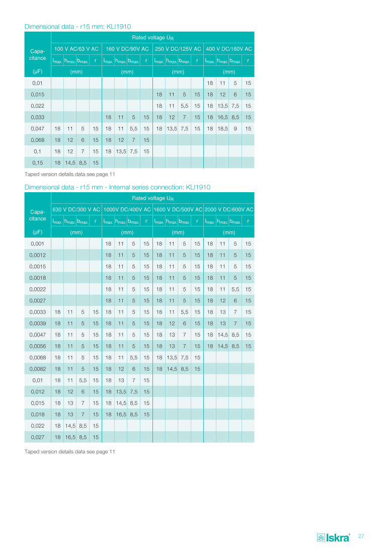
Dimensional data - r15 mm: KLI1910
Dimensional data - r15 mm - Internal series connection: KLI1910
Capa- citance
(μF)
Rated voltage UR
100 V AC/63 V AC 160 V DC/90V AC 250 V DC/125V AC 400 V DC/160V AC
Imax. hmax. bmax. r Imax. hmax. bmax. r Imax. hmax. bmax. r Imax. hmax. bmax. r
(mm) (mm) (mm) (mm)
0,01 18 11 5 15
0,015 18 11 5 15 18 12 6 15
0,022 18 11 5,5 15 18 13,5 7,5 15
0,033 18 11 5 15 18 12 7 15 18 16,5 8,5 15
0,047 18 11 5 15 18 11 5,5 15 18 13,5 7,5 15 18 18,5 9 15
0,068 18 12 6 15 18 12 7 15
0,1 18 12 7 15 18 13,5 7,5 15
0,15 18 14,5 8,5 15
Capa- citance
(μF)
Rated voltage UR
630 V DC/300 V AC 1000V DC/400V AC 1600 V DC/500V AC 2000 V DC/600V AC
Imax. hmax. bmax. r Imax. hmax. bmax. r Imax. hmax. bmax. r Imax. hmax. bmax. r
(mm) (mm) (mm) (mm)
0,001 18 11 5 15 18 11 5 15 18 11 5 15
0,0012 18 11 5 15 18 11 5 15 18 11 5 15
0,0015 18 11 5 15 18 11 5 15 18 11 5 15
0,0018 18 11 5 15 18 11 5 15 18 11 5 15
0,0022 18 11 5 15 18 11 5 15 18 11 5,5 15
0,0027 18 11 5 15 18 11 5 15 18 12 6 15
0,0033 18 11 5 15 18 11 5 15 18 11 5,5 15 18 13 7 15
0,0039 18 11 5 15 18 11 5 15 18 12 6 15 18 13 7 15
0,0047 18 11 5 15 18 11 5 15 18 13 7 15 18 14,5 8,5 15
0,0056 18 11 5 15 18 11 5 15 18 13 7 15 18 14,5 8,5 15
0,0068 18 11 5 15 18 11 5,5 15 18 13,5 7,5 15
0,0082 18 11 5 15 18 12 6 15 18 14,5 8,5 15
0,01 18 11 5,5 15 18 13 7 15
0,012 18 12 6 15 18 13,5 7,5 15
0,015 18 13 7 15 18 14,5 8,5 15
0,018 18 13 7 15 18 16,5 8,5 15
0,022 18 14,5 8,5 15
0,027 18 16,5 8,5 15
Taped version details data see page 11
Taped version details data see page 11
28
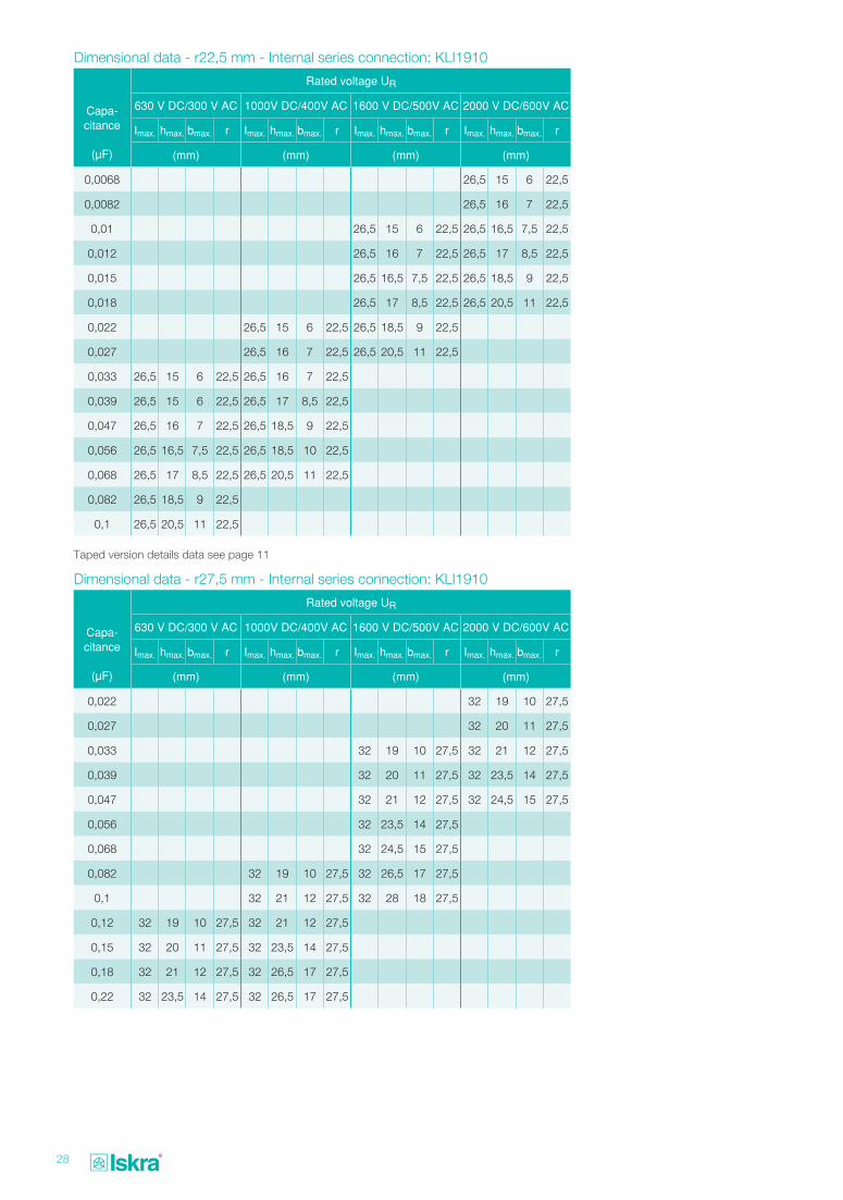
Dimensional data - r22,5 mm - Internal series connection: KLI1910
Dimensional data - r27,5 mm - Internal series connection: KLI1910
Capa- citance
(μF)
Rated voltage UR
630 V DC/300 V AC 1000V DC/400V AC 1600 V DC/500V AC 2000 V DC/600V AC
Imax. hmax. bmax. r Imax. hmax. bmax. r Imax. hmax. bmax. r Imax. hmax. bmax. r
(mm) (mm) (mm) (mm)
0,0068 26,5 15 6 22,5
0,0082 26,5 16 7 22,5
0,01 26,5 15 6 22,5 26,5 16,5 7,5 22,5
0,012 26,5 16 7 22,5 26,5 17 8,5 22,5
0,015 26,5 16,5 7,5 22,5 26,5 18,5 9 22,5
0,018 26,5 17 8,5 22,5 26,5 20,5 11 22,5
0,022 26,5 15 6 22,5 26,5 18,5 9 22,5
0,027 26,5 16 7 22,5 26,5 20,5 11 22,5
0,033 26,5 15 6 22,5 26,5 16 7 22,5
0,039 26,5 15 6 22,5 26,5 17 8,5 22,5
0,047 26,5 16 7 22,5 26,5 18,5 9 22,5
0,056 26,5 16,5 7,5 22,5 26,5 18,5 10 22,5
0,068 26,5 17 8,5 22,5 26,5 20,5 11 22,5
0,082 26,5 18,5 9 22,5
0,1 26,5 20,5 11 22,5
Capa- citance
(μF)
Rated voltage UR
630 V DC/300 V AC 1000V DC/400V AC 1600 V DC/500V AC 2000 V DC/600V AC
Imax. hmax. bmax. r Imax. hmax. bmax. r Imax. hmax. bmax. r Imax. hmax. bmax. r
(mm) (mm) (mm) (mm)
0,022 32 19 10 27,5
0,027 32 20 11 27,5
0,033 32 19 10 27,5 32 21 12 27,5
0,039 32 20 11 27,5 32 23,5 14 27,5
0,047 32 21 12 27,5 32 24,5 15 27,5
0,056 32 23,5 14 27,5
0,068 32 24,5 15 27,5
0,082 32 19 10 27,5 32 26,5 17 27,5
0,1 32 21 12 27,5 32 28 18 27,5
0,12 32 19 10 27,5 32 21 12 27,5
0,15 32 20 11 27,5 32 23,5 14 27,5
0,18 32 21 12 27,5 32 26,5 17 27,5
0,22 32 23,5 14 27,5 32 26,5 17 27,5
Taped version details data see page 11
29
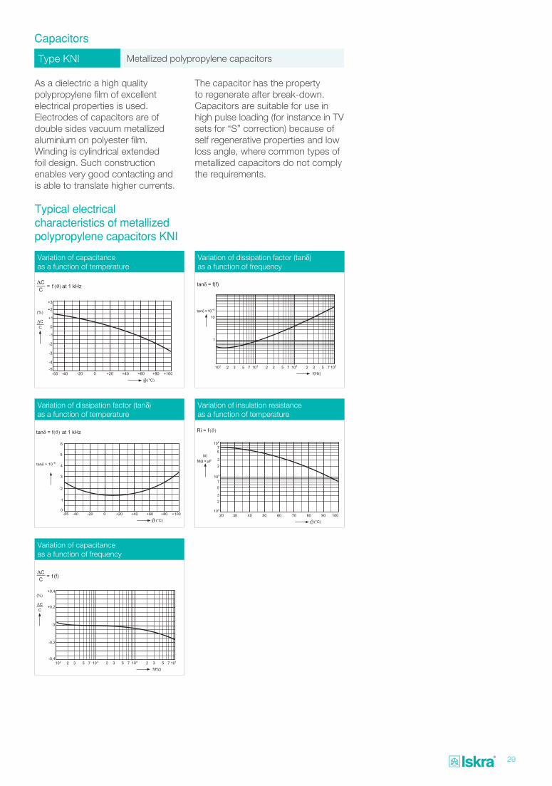
Type KNI Metallized polypropylene capacitors
Capacitors
As a dielectric a high quality polypropylene film of excellent electrical properties is used. Electrodes of capacitors are of double sides vacuum metallized aluminium on polyester film. Winding is cylindrical extended foil design. Such construction enables very good contacting and is able to translate higher currents.
Typical electrical characteristics of metallized polypropylene capacitors KNI
The capacitor has the property to regenerate after break-down. Capacitors are suitable for use in high pulse loading (for instance in TV sets for “S” correction) because of self regenerative properties and low loss angle, where common types of metallized capacitors do not comply the requirements.
Variation of capacitance as a function of temperature
Variation of dissipation factor (tanδ) as a function of temperature
Variation of capacitance as a function of frequency
Variation of dissipation factor (tanδ) as a function of frequency
Variation of insulation resistance as a function of temperature
ϑ
ϑ ϑ
30
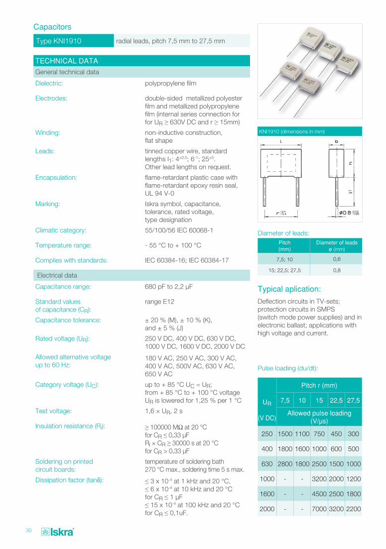
Type KNI1910 radial leads, pitch 7,5 mm to 27,5 mm
Capacitors
TECHNICAL DATA
General technical data
Dielectric: polypropylene film
Electrodes: double-sided metallized polyester film and metallized polypropylene film (internal series connection for for UR ≥ 630V DC and r ≥ 15mm)
Winding: non-inductive construction, flat shape
Leads: tinned copper wire, standard lengths l1: 4±0,5; 6-1; 25±5. Other lead lengths on request.
Encapsulation: flame-retardant plastic case with flame-retardant epoxy resin seal, UL 94 V-0
Marking: Iskra symbol, capacitance, tolerance, rated voltage, type designation
Climatic category: 55/100/56 IEC 60068-1
Temperature range: - 55 °C to + 100 °C
Complies with standards: IEC 60384-16; IEC 60384-17
Electrical data
Capacitance range: 680 pF to 2,2 μF
Standard values of capacitance (CR):
range E12
Capacitance tolerance: ± 20 % (M), ± 10 % (K), and ± 5 % (J)
Rated voltage (UR): 250 V DC, 400 V DC, 630 V DC, 1000 V DC, 1600 V DC, 2000 V DC
Allowed alternative voltage up to 60 Hz:
180 V AC, 250 V AC, 300 V AC, 400 V AC, 500V AC, 630 V AC, 650 V AC
Category voltage (UC): up to + 85 °C UC = UR; from + 85 °C to + 100 °C voltage UR is lowered for 1,25 % per 1 °C
Test voltage: 1,6 × UR, 2 s
Insulation resistance (Ri): ≥ 100000 MΩ at 20 °C for CR ≤ 0,33 μFRi × CR ≥ 30000 s at 20 °C for CR > 0,33 μF
Soldering on printed circuit boards:
temperature of soldering bath 270 °C max., soldering time 5 s max.
Dissipation factor (tanδ): ≤ 3 x 10⁻⁴ at 1 kHz and 20 °C, ≤ 6 x 10⁻⁴ at 10 kHz and 20 °C for CR ≤ 1 μF≤ 15 x 10-4 at 100 kHz and 20 °C for CR ≤ 0,1uF.
KNI1910 (dimensions in mm)
Pulse loading (du/dt):
UR
(V DC)
Pitch r (mm)
7,5 10 15 22,5 27,5
Allowed pulse loading (V/μs)
250 1500 1100 750 450 300
400 1800 1600 1000 600 500
630 2800 1800 2500 1500 1000
1000 - - 3200 2000 1200
1600 - - 4500 2500 1800
2000 - - 7000 3200 2200
Pitch(mm)
Diameter of leads ø (mm)
7,5; 10 0,6
15; 22,5; 27,5 0,8
Diameter of leads:
Typical aplication:
Deflection circuits in TV-sets; protection circuits in SMPS (switch mode power supplies) and in electronic ballast; applications with high voltage and current.
31
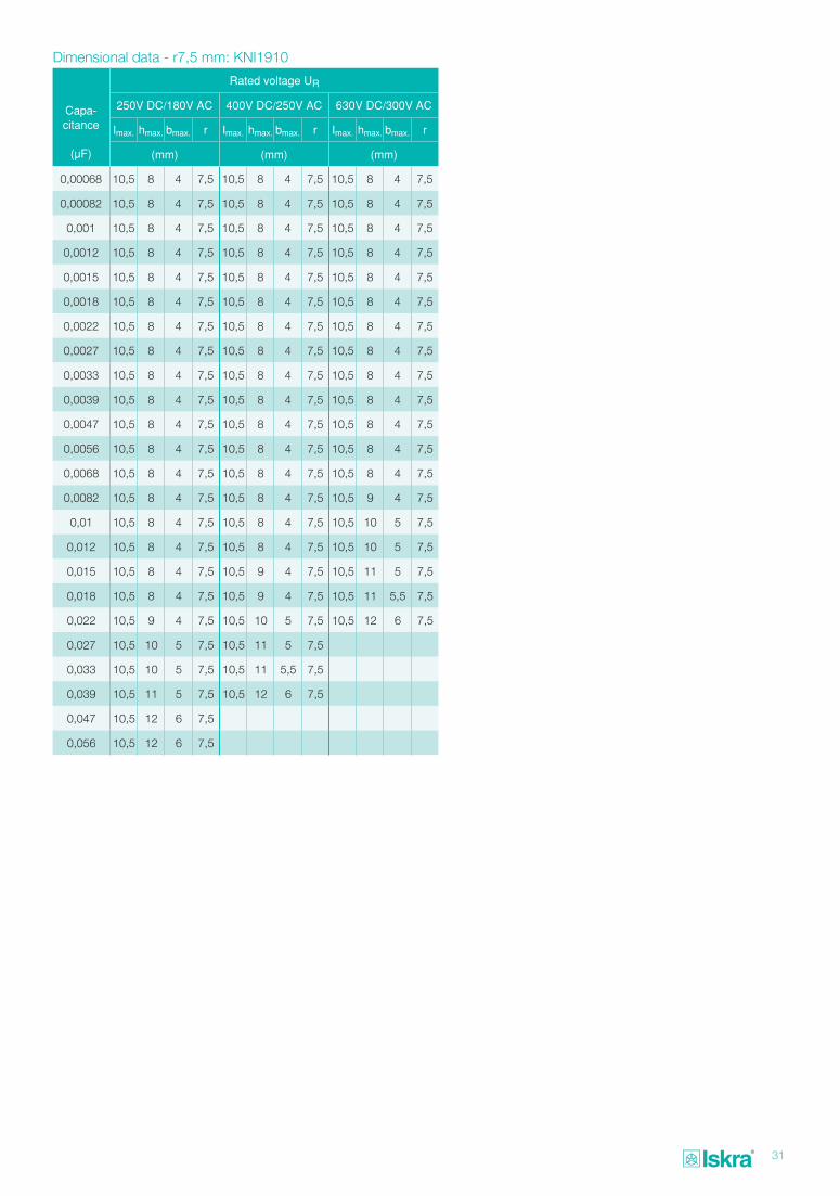
Dimensional data - r7,5 mm: KNI1910
Capa- citance
(μF)
Rated voltage UR
250V DC/180V AC 400V DC/250V AC 630V DC/300V AC
Imax. hmax. bmax. r Imax. hmax. bmax. r Imax. hmax. bmax. r
(mm) (mm) (mm)
0,00068 10,5 8 4 7,5 10,5 8 4 7,5 10,5 8 4 7,5
0,00082 10,5 8 4 7,5 10,5 8 4 7,5 10,5 8 4 7,5
0,001 10,5 8 4 7,5 10,5 8 4 7,5 10,5 8 4 7,5
0,0012 10,5 8 4 7,5 10,5 8 4 7,5 10,5 8 4 7,5
0,0015 10,5 8 4 7,5 10,5 8 4 7,5 10,5 8 4 7,5
0,0018 10,5 8 4 7,5 10,5 8 4 7,5 10,5 8 4 7,5
0,0022 10,5 8 4 7,5 10,5 8 4 7,5 10,5 8 4 7,5
0,0027 10,5 8 4 7,5 10,5 8 4 7,5 10,5 8 4 7,5
0,0033 10,5 8 4 7,5 10,5 8 4 7,5 10,5 8 4 7,5
0,0039 10,5 8 4 7,5 10,5 8 4 7,5 10,5 8 4 7,5
0,0047 10,5 8 4 7,5 10,5 8 4 7,5 10,5 8 4 7,5
0,0056 10,5 8 4 7,5 10,5 8 4 7,5 10,5 8 4 7,5
0,0068 10,5 8 4 7,5 10,5 8 4 7,5 10,5 8 4 7,5
0,0082 10,5 8 4 7,5 10,5 8 4 7,5 10,5 9 4 7,5
0,01 10,5 8 4 7,5 10,5 8 4 7,5 10,5 10 5 7,5
0,012 10,5 8 4 7,5 10,5 8 4 7,5 10,5 10 5 7,5
0,015 10,5 8 4 7,5 10,5 9 4 7,5 10,5 11 5 7,5
0,018 10,5 8 4 7,5 10,5 9 4 7,5 10,5 11 5,5 7,5
0,022 10,5 9 4 7,5 10,5 10 5 7,5 10,5 12 6 7,5
0,027 10,5 10 5 7,5 10,5 11 5 7,5
0,033 10,5 10 5 7,5 10,5 11 5,5 7,5
0,039 10,5 11 5 7,5 10,5 12 6 7,5
0,047 10,5 12 6 7,5
0,056 10,5 12 6 7,5
32
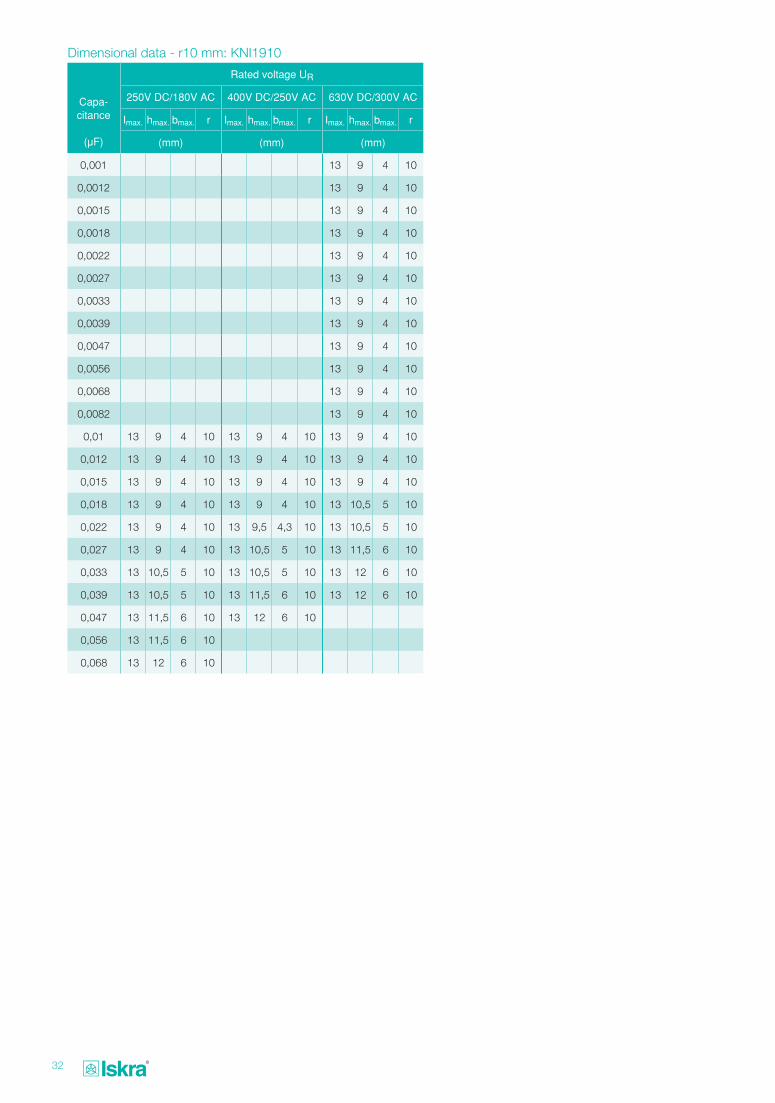
Dimensional data - r10 mm: KNI1910
Capa- citance
(μF)
Rated voltage UR
250V DC/180V AC 400V DC/250V AC 630V DC/300V AC
Imax. hmax. bmax. r Imax. hmax. bmax. r Imax. hmax. bmax. r
(mm) (mm) (mm)
0,001 13 9 4 10
0,0012 13 9 4 10
0,0015 13 9 4 10
0,0018 13 9 4 10
0,0022 13 9 4 10
0,0027 13 9 4 10
0,0033 13 9 4 10
0,0039 13 9 4 10
0,0047 13 9 4 10
0,0056 13 9 4 10
0,0068 13 9 4 10
0,0082 13 9 4 10
0,01 13 9 4 10 13 9 4 10 13 9 4 10
0,012 13 9 4 10 13 9 4 10 13 9 4 10
0,015 13 9 4 10 13 9 4 10 13 9 4 10
0,018 13 9 4 10 13 9 4 10 13 10,5 5 10
0,022 13 9 4 10 13 9,5 4,3 10 13 10,5 5 10
0,027 13 9 4 10 13 10,5 5 10 13 11,5 6 10
0,033 13 10,5 5 10 13 10,5 5 10 13 12 6 10
0,039 13 10,5 5 10 13 11,5 6 10 13 12 6 10
0,047 13 11,5 6 10 13 12 6 10
0,056 13 11,5 6 10
0,068 13 12 6 10
33
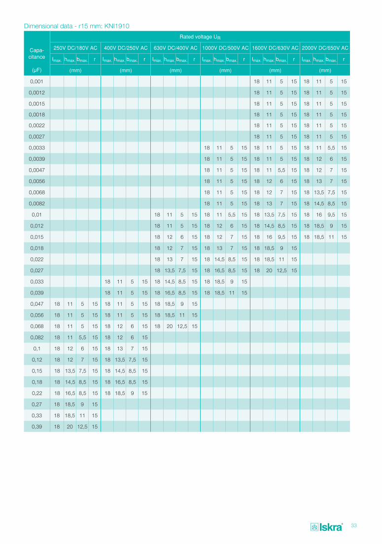
Dimensional data - r15 mm: KNI1910
Capa- citance
(μF)
Rated voltage UR
250V DC/180V AC 400V DC/250V AC 630V DC/400V AC 1000V DC/500V AC 1600V DC/630V AC 2000V DC/650V AC
Imax. hmax. bmax. r Imax. hmax. bmax. r Imax. hmax. bmax. r Imax. hmax. bmax. r Imax. hmax. bmax. r Imax. hmax. bmax. r
(mm) (mm) (mm) (mm) (mm) (mm)
0,001 18 11 5 15 18 11 5 15
0,0012 18 11 5 15 18 11 5 15
0,0015 18 11 5 15 18 11 5 15
0,0018 18 11 5 15 18 11 5 15
0,0022 18 11 5 15 18 11 5 15
0,0027 18 11 5 15 18 11 5 15
0,0033 18 11 5 15 18 11 5 15 18 11 5,5 15
0,0039 18 11 5 15 18 11 5 15 18 12 6 15
0,0047 18 11 5 15 18 11 5,5 15 18 12 7 15
0,0056 18 11 5 15 18 12 6 15 18 13 7 15
0,0068 18 11 5 15 18 12 7 15 18 13,5 7,5 15
0,0082 18 11 5 15 18 13 7 15 18 14,5 8,5 15
0,01 18 11 5 15 18 11 5,5 15 18 13,5 7,5 15 18 16 9,5 15
0,012 18 11 5 15 18 12 6 15 18 14,5 8,5 15 18 18,5 9 15
0,015 18 12 6 15 18 12 7 15 18 16 9,5 15 18 18,5 11 15
0,018 18 12 7 15 18 13 7 15 18 18,5 9 15
0,022 18 13 7 15 18 14,5 8,5 15 18 18,5 11 15
0,027 18 13,5 7,5 15 18 16,5 8,5 15 18 20 12,5 15
0,033 18 11 5 15 18 14,5 8,5 15 18 18,5 9 15
0,039 18 11 5 15 18 16,5 8,5 15 18 18,5 11 15
0,047 18 11 5 15 18 11 5 15 18 18,5 9 15
0,056 18 11 5 15 18 11 5 15 18 18,5 11 15
0,068 18 11 5 15 18 12 6 15 18 20 12,5 15
0,082 18 11 5,5 15 18 12 6 15
0,1 18 12 6 15 18 13 7 15
0,12 18 12 7 15 18 13,5 7,5 15
0,15 18 13,5 7,5 15 18 14,5 8,5 15
0,18 18 14,5 8,5 15 18 16,5 8,5 15
0,22 18 16,5 8,5 15 18 18,5 9 15
0,27 18 18,5 9 15
0,33 18 18,5 11 15
0,39 18 20 12,5 15
34
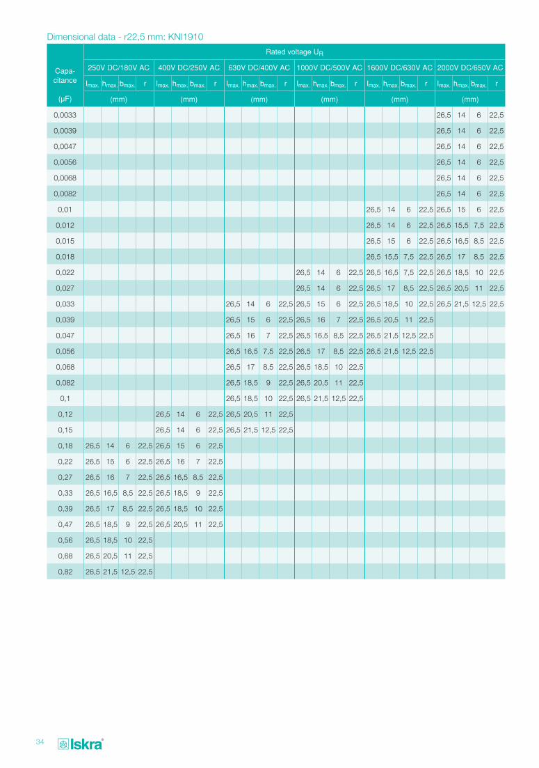
Dimensional data - r22,5 mm: KNI1910
Capa- citance
(μF)
Rated voltage UR
250V DC/180V AC 400V DC/250V AC 630V DC/400V AC 1000V DC/500V AC 1600V DC/630V AC 2000V DC/650V AC
Imax. hmax. bmax. r Imax. hmax. bmax. r Imax. hmax. bmax. r Imax. hmax. bmax. r Imax. hmax. bmax. r Imax. hmax. bmax. r
(mm) (mm) (mm) (mm) (mm) (mm)
0,0033 26,5 14 6 22,5
0,0039 26,5 14 6 22,5
0,0047 26,5 14 6 22,5
0,0056 26,5 14 6 22,5
0,0068 26,5 14 6 22,5
0,0082 26,5 14 6 22,5
0,01 26,5 14 6 22,5 26,5 15 6 22,5
0,012 26,5 14 6 22,5 26,5 15,5 7,5 22,5
0,015 26,5 15 6 22,5 26,5 16,5 8,5 22,5
0,018 26,5 15,5 7,5 22,5 26,5 17 8,5 22,5
0,022 26,5 14 6 22,5 26,5 16,5 7,5 22,5 26,5 18,5 10 22,5
0,027 26,5 14 6 22,5 26,5 17 8,5 22,5 26,5 20,5 11 22,5
0,033 26,5 14 6 22,5 26,5 15 6 22,5 26,5 18,5 10 22,5 26,5 21,5 12,5 22,5
0,039 26,5 15 6 22,5 26,5 16 7 22,5 26,5 20,5 11 22,5
0,047 26,5 16 7 22,5 26,5 16,5 8,5 22,5 26,5 21,5 12,5 22,5
0,056 26,5 16,5 7,5 22,5 26,5 17 8,5 22,5 26,5 21,5 12,5 22,5
0,068 26,5 17 8,5 22,5 26,5 18,5 10 22,5
0,082 26,5 18,5 9 22,5 26,5 20,5 11 22,5
0,1 26,5 18,5 10 22,5 26,5 21,5 12,5 22,5
0,12 26,5 14 6 22,5 26,5 20,5 11 22,5
0,15 26,5 14 6 22,5 26,5 21,5 12,5 22,5
0,18 26,5 14 6 22,5 26,5 15 6 22,5
0,22 26,5 15 6 22,5 26,5 16 7 22,5
0,27 26,5 16 7 22,5 26,5 16,5 8,5 22,5
0,33 26,5 16,5 8,5 22,5 26,5 18,5 9 22,5
0,39 26,5 17 8,5 22,5 26,5 18,5 10 22,5
0,47 26,5 18,5 9 22,5 26,5 20,5 11 22,5
0,56 26,5 18,5 10 22,5
0,68 26,5 20,5 11 22,5
0,82 26,5 21,5 12,5 22,5
35
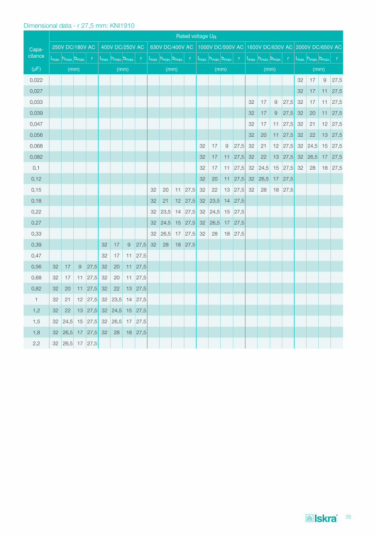
Dimensional data - r 27,5 mm: KNI1910
Capa- citance
(μF)
Rated voltage UR
250V DC/180V AC 400V DC/250V AC 630V DC/400V AC 1000V DC/500V AC 1600V DC/630V AC 2000V DC/650V AC
Imax. hmax. bmax. r Imax. hmax. bmax. r Imax. hmax. bmax. r Imax. hmax. bmax. r Imax. hmax. bmax. r Imax. hmax. bmax. r
(mm) (mm) (mm) (mm) (mm) (mm)
0,022 32 17 9 27,5
0,027 32 17 11 27,5
0,033 32 17 9 27,5 32 17 11 27,5
0,039 32 17 9 27,5 32 20 11 27,5
0,047 32 17 11 27,5 32 21 12 27,5
0,056 32 20 11 27,5 32 22 13 27,5
0,068 32 17 9 27,5 32 21 12 27,5 32 24,5 15 27,5
0,082 32 17 11 27,5 32 22 13 27,5 32 26,5 17 27,5
0,1 32 17 11 27,5 32 24,5 15 27,5 32 28 18 27,5
0,12 32 20 11 27,5 32 26,5 17 27,5
0,15 32 20 11 27,5 32 22 13 27,5 32 28 18 27,5
0,18 32 21 12 27,5 32 23,5 14 27,5
0,22 32 23,5 14 27,5 32 24,5 15 27,5
0,27 32 24,5 15 27,5 32 26,5 17 27,5
0,33 32 26,5 17 27,5 32 28 18 27,5
0,39 32 17 9 27,5 32 28 18 27,5
0,47 32 17 11 27,5
0,56 32 17 9 27,5 32 20 11 27,5
0,68 32 17 11 27,5 32 20 11 27,5
0,82 32 20 11 27,5 32 22 13 27,5
1 32 21 12 27,5 32 23,5 14 27,5
1,2 32 22 13 27,5 32 24,5 15 27,5
1,5 32 24,5 15 27,5 32 26,5 17 27,5
1,8 32 26,5 17 27,5 32 28 18 27,5
2,2 32 26,5 17 27,5
36
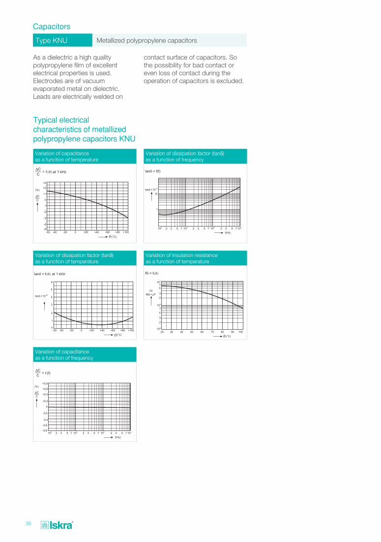
Type KNU Metallized polypropylene capacitors
Capacitors
As a dielectric a high quality polypropylene film of excellent electrical properties is used. Electrodes are of vacuum evaporated metal on dielectric. Leads are electrically welded on
Typical electrical characteristics of metallized polypropylene capacitors KNU
contact surface of capacitors. So the possibility for bad contact or even loss of contact during the operation of capacitors is excluded.
Variation of capacitance as a function of temperature
Variation of dissipation factor (tanδ) as a function of temperature
Variation of capacitance as a function of frequency
Variation of dissipation factor (tanδ) as a function of frequency
Variation of insulation resistance as a function of temperature
ϑϑ
ϑ
37
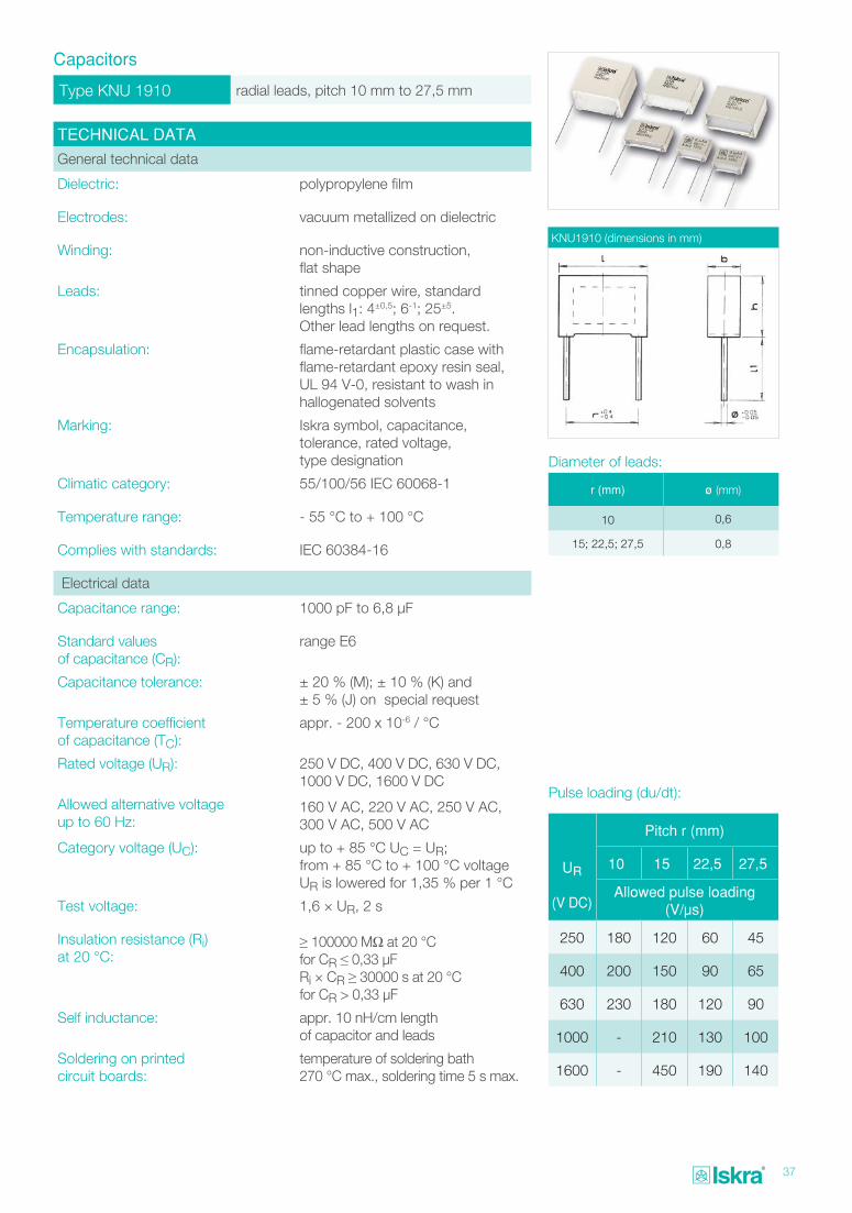
Type KNU 1910 radial leads, pitch 10 mm to 27,5 mm
Capacitors
TECHNICAL DATA
General technical data
Dielectric: polypropylene film
Electrodes: vacuum metallized on dielectric
Winding: non-inductive construction, flat shape
Leads: tinned copper wire, standard lengths l1: 4±0,5; 6-1; 25±5. Other lead lengths on request.
Encapsulation: flame-retardant plastic case with flame-retardant epoxy resin seal, UL 94 V-0, resistant to wash in hallogenated solvents
Marking: Iskra symbol, capacitance, tolerance, rated voltage, type designation
Climatic category: 55/100/56 IEC 60068-1
Temperature range: - 55 °C to + 100 °C
Complies with standards: IEC 60384-16
Electrical data
Capacitance range: 1000 pF to 6,8 μF
Standard values of capacitance (CR):
range E6
Capacitance tolerance: ± 20 % (M); ± 10 % (K) and ± 5 % (J) on special request
Temperature coefficient of capacitance (TC):
appr. - 200 x 10-6 / °C
Rated voltage (UR): 250 V DC, 400 V DC, 630 V DC, 1000 V DC, 1600 V DC
Allowed alternative voltage up to 60 Hz:
160 V AC, 220 V AC, 250 V AC, 300 V AC, 500 V AC
Category voltage (UC): up to + 85 °C UC = UR; from + 85 °C to + 100 °C voltage UR is lowered for 1,35 % per 1 °C
Test voltage: 1,6 × UR, 2 s
Insulation resistance (Ri) at 20 °C:
≥ 100000 MΩ at 20 °C for CR ≤ 0,33 μFRi × CR ≥ 30000 s at 20 °C for CR > 0,33 μF
Self inductance: appr. 10 nH/cm length of capacitor and leads
Soldering on printed circuit boards:
temperature of soldering bath 270 °C max., soldering time 5 s max.
KNU1910 (dimensions in mm)
Pulse loading (du/dt):
UR
(V DC)
Pitch r (mm)
10 15 22,5 27,5
Allowed pulse loading (V/μs)
250 180 120 60 45
400 200 150 90 65
630 230 180 120 90
1000 - 210 130 100
1600 - 450 190 140
r (mm) ø (mm)
10 0,6
15; 22,5; 27,5 0,8
Diameter of leads:
38
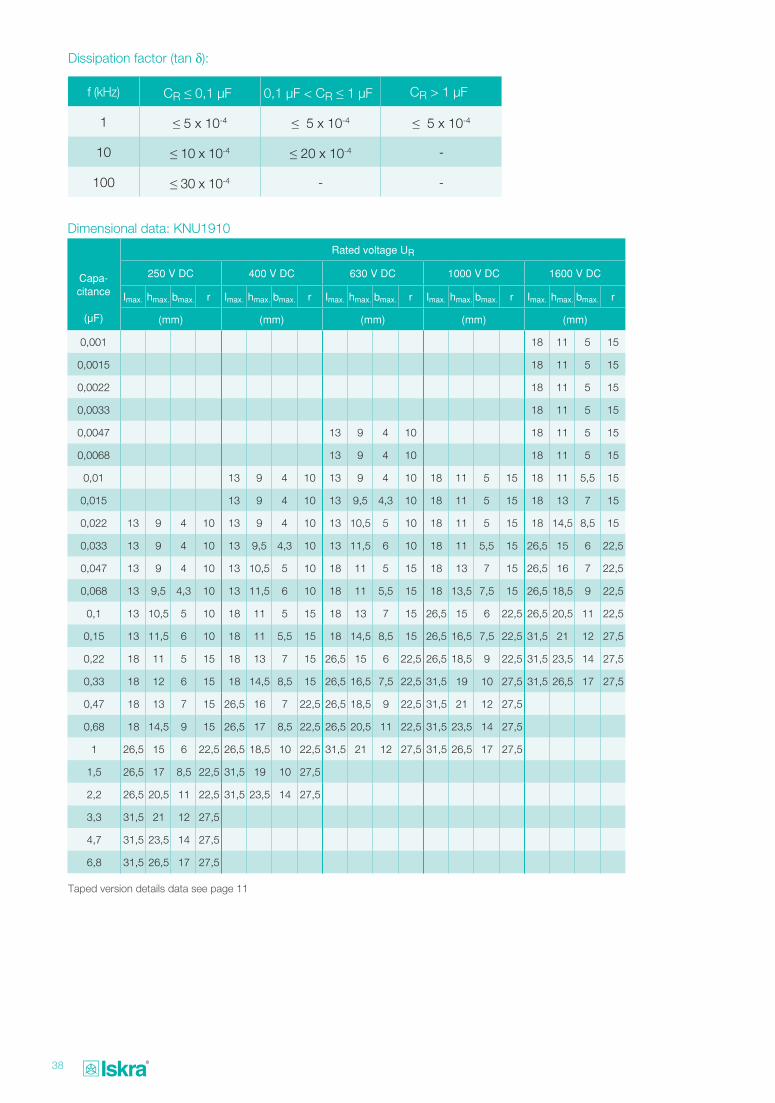
Dissipation factor (tan δ):
f (kHz) CR ≤ 0,1 μF 0,1 μF < CR ≤ 1 μF CR > 1 μF
1 ≤ 5 x 10⁻⁴ ≤ 5 x 10⁻⁴ ≤ 5 x 10⁻⁴
10 ≤ 10 x 10-4 ≤ 20 x 10-4 -
100 ≤ 30 x 10-4 - -
Dimensional data: KNU1910
Capa- citance
(μF)
Rated voltage UR
250 V DC 400 V DC 630 V DC 1000 V DC 1600 V DC
Imax. hmax. bmax. r Imax. hmax. bmax. r Imax. hmax. bmax. r Imax. hmax. bmax. r Imax. hmax. bmax. r
(mm) (mm) (mm) (mm) (mm)
0,001 18 11 5 15
0,0015 18 11 5 15
0,0022 18 11 5 15
0,0033 18 11 5 15
0,0047 13 9 4 10 18 11 5 15
0,0068 13 9 4 10 18 11 5 15
0,01 13 9 4 10 13 9 4 10 18 11 5 15 18 11 5,5 15
0,015 13 9 4 10 13 9,5 4,3 10 18 11 5 15 18 13 7 15
0,022 13 9 4 10 13 9 4 10 13 10,5 5 10 18 11 5 15 18 14,5 8,5 15
0,033 13 9 4 10 13 9,5 4,3 10 13 11,5 6 10 18 11 5,5 15 26,5 15 6 22,5
0,047 13 9 4 10 13 10,5 5 10 18 11 5 15 18 13 7 15 26,5 16 7 22,5
0,068 13 9,5 4,3 10 13 11,5 6 10 18 11 5,5 15 18 13,5 7,5 15 26,5 18,5 9 22,5
0,1 13 10,5 5 10 18 11 5 15 18 13 7 15 26,5 15 6 22,5 26,5 20,5 11 22,5
0,15 13 11,5 6 10 18 11 5,5 15 18 14,5 8,5 15 26,5 16,5 7,5 22,5 31,5 21 12 27,5
0,22 18 11 5 15 18 13 7 15 26,5 15 6 22,5 26,5 18,5 9 22,5 31,5 23,5 14 27,5
0,33 18 12 6 15 18 14,5 8,5 15 26,5 16,5 7,5 22,5 31,5 19 10 27,5 31,5 26,5 17 27,5
0,47 18 13 7 15 26,5 16 7 22,5 26,5 18,5 9 22,5 31,5 21 12 27,5
0,68 18 14,5 9 15 26,5 17 8,5 22,5 26,5 20,5 11 22,5 31,5 23,5 14 27,5
1 26,5 15 6 22,5 26,5 18,5 10 22,5 31,5 21 12 27,5 31,5 26,5 17 27,5
1,5 26,5 17 8,5 22,5 31,5 19 10 27,5
2,2 26,5 20,5 11 22,5 31,5 23,5 14 27,5
3,3 31,5 21 12 27,5
4,7 31,5 23,5 14 27,5
6,8 31,5 26,5 17 27,5
Taped version details data see page 11

Concept, design and production: Poanta, d.o.o. [email protected]
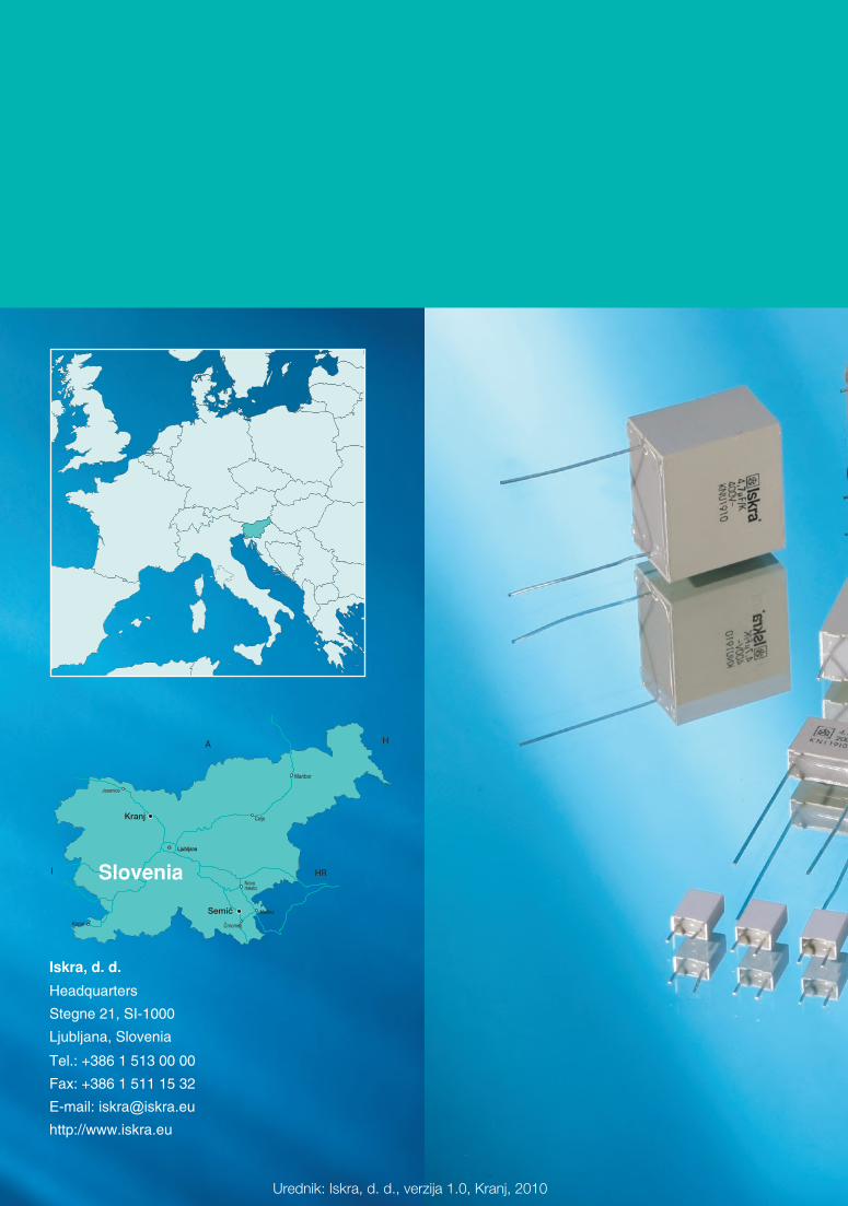
Iskra, d. d. Headquarters
Stegne 21, SI-1000
Ljubljana, Slovenia
Tel.: +386 1 513 00 00
Fax: +386 1 511 15 32
E-mail: [email protected]
http://www.iskra.eu
Urednik: Iskra, d. d., verzija 1.0, Kranj, 2010
Ljubljana
HA
INovo mesto
Metlika
Crnomelj
Maribor
Jesenice
Koper
HR
Celje
Slovenia
SemiË
Kranj


![Flexión de los temas consonánticos - Universidad de … 21.pdfz< adjetivo *γυναικός: Szemerényi (1960) [Chantraine, Dictionnaire…243] z< vocativo γύναι+ alargamiento](https://static.fdocument.org/doc/165x107/5ae5310a7f8b9a3d3b8b8bb8/flexin-de-los-temas-consonnticos-universidad-de-21pdfz-adjetivo-.jpg)