Bending Stresses Due to Stationary Loads
15
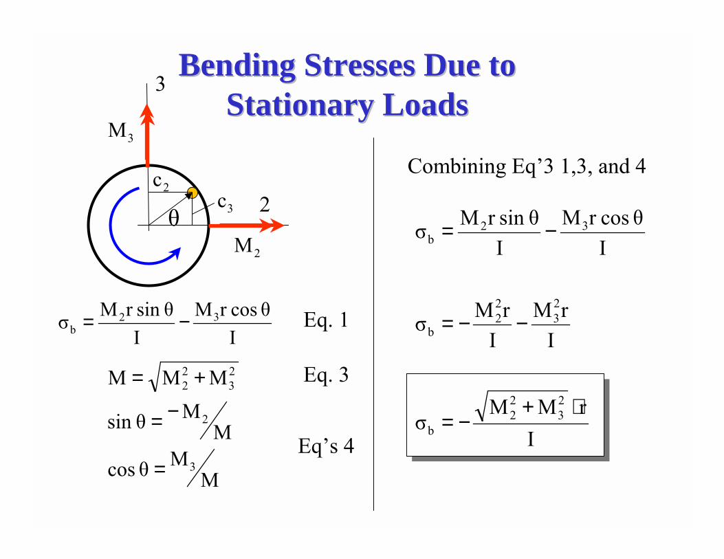
Bending Stresses Due to Bending Stresses Due to Stationary Loads Stationary Loads 2 M 3 M θ 3 2 2 c 3 c I θ cos r M I θ sin r M σ 3 2 b − = Eq. 1 M M θ cos M M θ sin M M M 3 2 2 3 2 2 = − = + = Eq. 3 Eqs 4 Combining Eq3 1,3, and 4 I r M M σ I r M I r M σ I θ cos r M I θ sin r M σ 2 3 2 2 b 2 3 2 2 b 3 2 b ⋅ + − = − − = − =
Transcript of Bending Stresses Due to Stationary Loads
Bending Stresses Due to Bending Stresses Due to Stationary LoadsStationary Loads
2M
3M
θ
3
22c
3c
Iθ cosr M
Iθsin r Mσ 32
b −= Eq. 1
MMθ cos
MMθsin
MMM
3
2
23
22
=
−=
+= Eq. 3
Eq�s 4
Combining Eq�3 1,3, and 4
IrMM
σ
IrM
IrMσ
Iθ cosr M
Iθsin r Mσ
23
22
b
23
22
b
32b
⋅+−=
−−=
−=
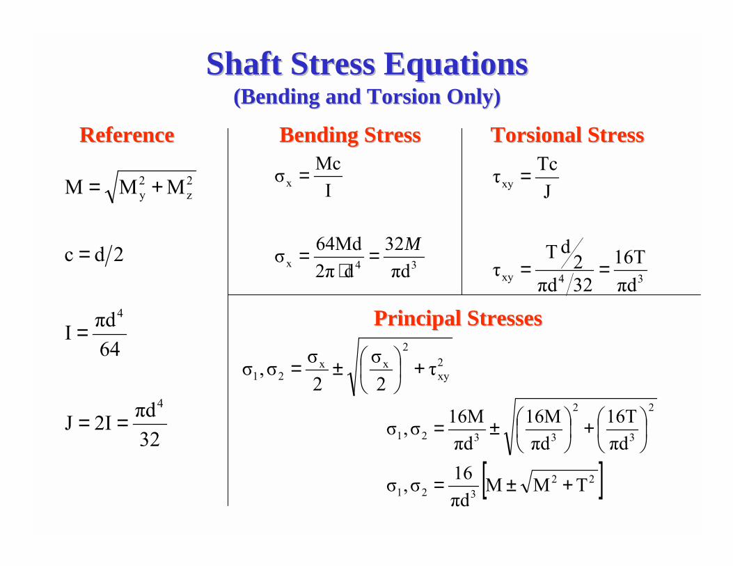
Shaft Stress EquationsShaft Stress Equations(Bending and Torsion Only)(Bending and Torsion Only)
34x
x
πd32
d2π64Mdσ
IMcσ
M=⋅
=
=
32πd2IJ
64πdI
2dc
MMM
4
4
2z
2y
==
=
=
+=
34xy
xy
πd16T
32πd2
dTτ
JTcτ
==
=
Bending StressBending Stress Torsional Torsional StressStressReferenceReference
Principal StressesPrincipal Stresses
2xy
2xx
21 τ2σ
2σσ,σ +�
�
���
�±=
[ ]22321
2
3
2
3321
TMMπd16σ,σ
πd16T
πd16M
πd16Mσ,σ
+±=
��
���
�+��
���
�±=
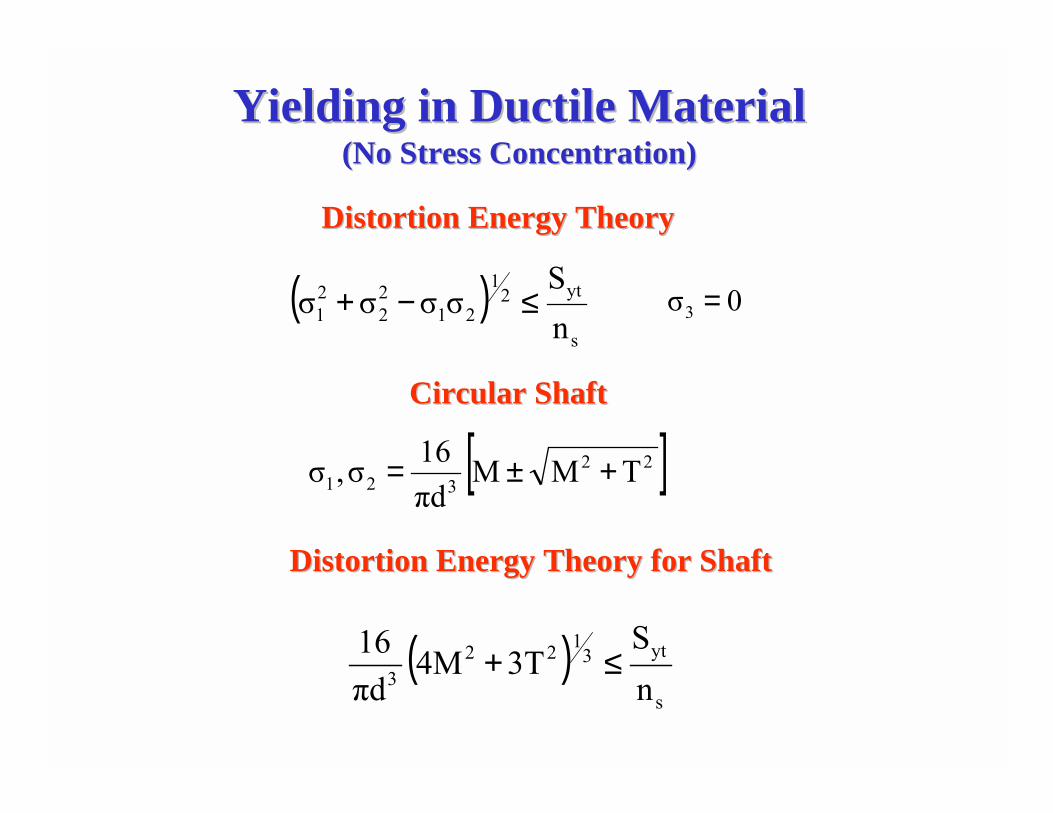
Yielding in Ductile MaterialYielding in Ductile Material(No Stress Concentration)(No Stress Concentration)
( )s
yt21
2122
21 n
Sσσσσ ≤−+
Distortion Energy TheoryDistortion Energy Theory
0σ3 =
[ ]22321 TMM
πd16σ,σ +±=
Circular ShaftCircular Shaft
Distortion Energy Theory for ShaftDistortion Energy Theory for Shaft
( )s
yt3122
3 nS
3T4Mπd16 ≤+
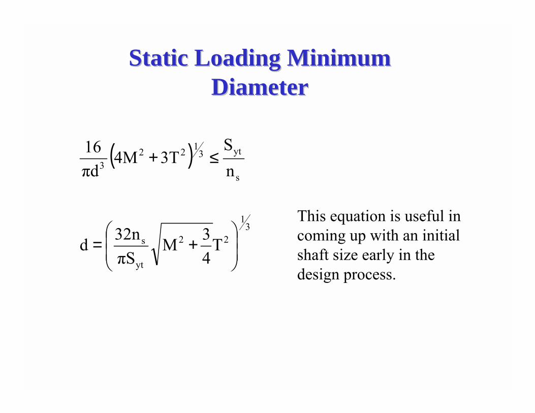
Static Loading Minimum Static Loading Minimum DiameterDiameter
( )
31
22
yt
s
s
yt3122
3
T43M
πS32nd
nS
3T4Mπd16
��
�
�
��
�
�+=
≤+
This equation is useful in coming up with an initial shaft size early in the design process.
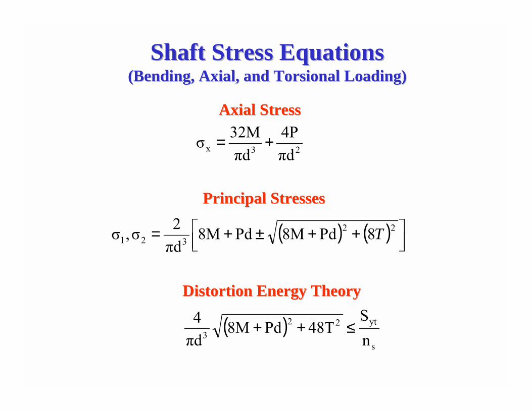
Shaft Stress EquationsShaft Stress Equations(Bending, Axial, and (Bending, Axial, and Torsional Torsional Loading)Loading)
( ) ( )
( )s
yt223
22321
23x
nS
48TPd8Mπd4
8Pd8MPd8Mπd2σ,σ
πd4P
πd32Mσ
≤++
���
��� ++±+=
+=
T
Axial StressAxial Stress
Principal StressesPrincipal Stresses
Distortion Energy TheoryDistortion Energy Theory
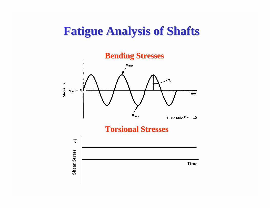
Fatigue Analysis of ShaftsFatigue Analysis of Shafts
Time
τ
Shea
r St
ress
Bending StressesBending Stresses
Torsional Torsional StressesStresses
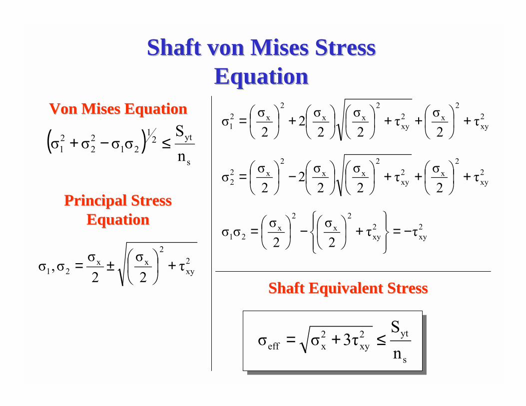
Shaft von Shaft von Mises Mises Stress Stress EquationEquation
( )s
yt21
2122
21 n
Sσσσσ ≤−+
2xy
2xx
21 τ2σ
2σσ,σ +�
�
���
�±=
2xy
2x2
xy
2xx
2x2
1 τ2στ
2σ
2σ2
2σσ +�
�
���
�++��
���
���
���
�+��
���
�=
2xy
2x2
xy
2xx
2x2
2 τ2στ
2σ
2σ2
2σσ +�
�
���
�++��
���
���
���
�−��
���
�=
2xy
2xy
2x
2x
21 ττ2σ
2σσσ −=
��
���
��
���
+�
��
−�
��
=
Von Von Mises Mises EquationEquation
Principal Stress Principal Stress EquationEquation
s
yt2xy
2xeff n
S3τσσ ≤+=
Shaft Equivalent StressShaft Equivalent Stress
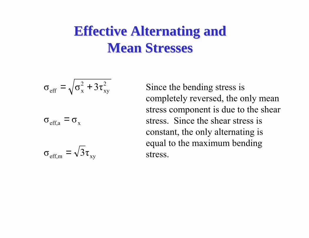
Effective Alternating and Effective Alternating and Mean StressesMean Stresses
xymeff,
xaeff,
2xy
2xeff
τ3σ
σσ
3τσσ
=
=
+= Since the bending stress is completely reversed, the only mean stress component is due to the shear stress. Since the shear stress is constant, the only alternating is equal to the maximum bending stress.
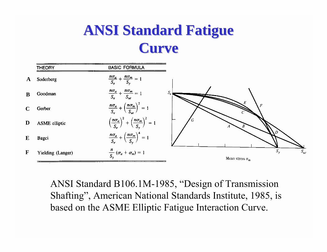
ANSI Standard Fatigue ANSI Standard Fatigue CurveCurve
A
D
B
C
E
F
ANSI Standard B106.1M-1985, �Design of Transmission Shafting�, American National Standards Institute, 1985, is based on the ASME Elliptic Fatigue Interaction Curve.
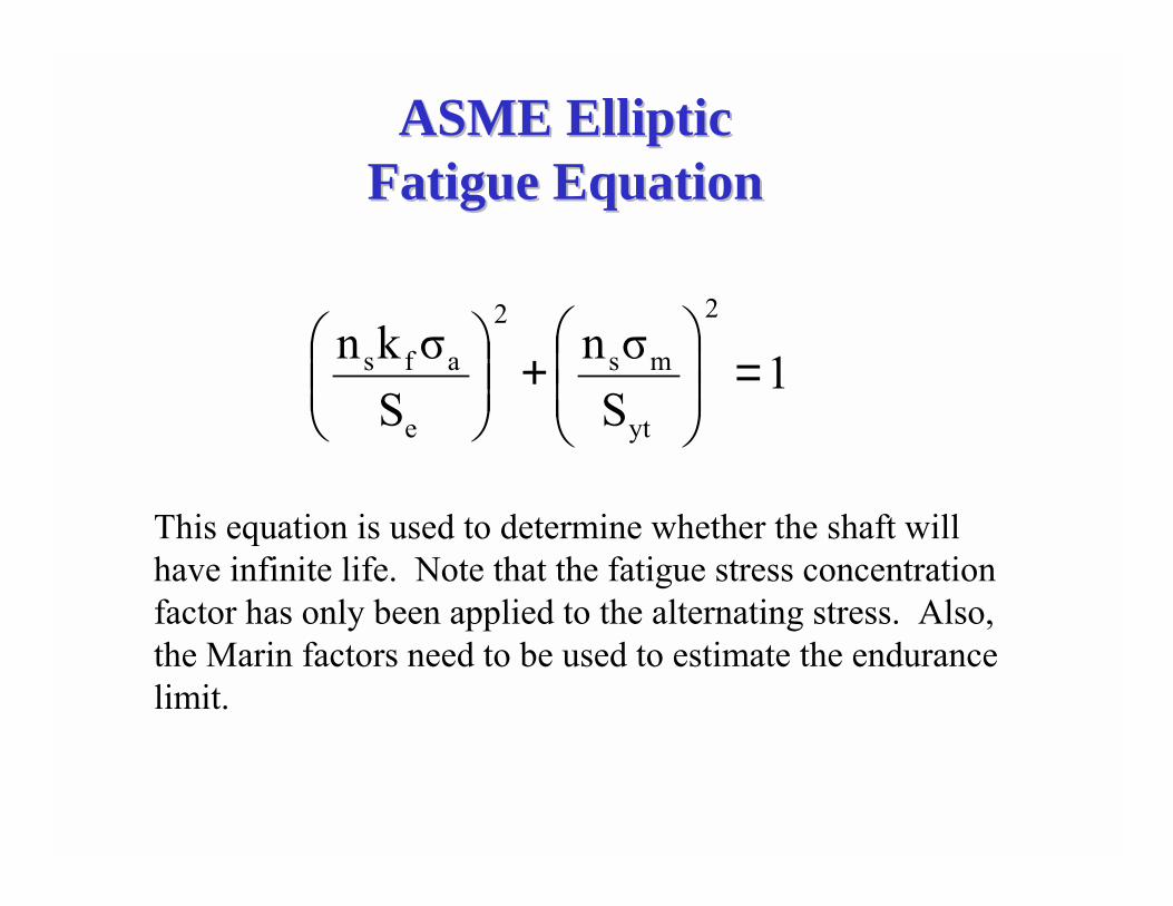
ASME Elliptic ASME Elliptic Fatigue EquationFatigue Equation
1Sσn
Sσkn
2
yt
ms
2
e
afs =��
�
�
��
�
�+��
�
����
�
This equation is used to determine whether the shaft will have infinite life. Note that the fatigue stress concentration factor has only been applied to the alternating stress. Also, the Marin factors need to be used to estimate the endurance limit.
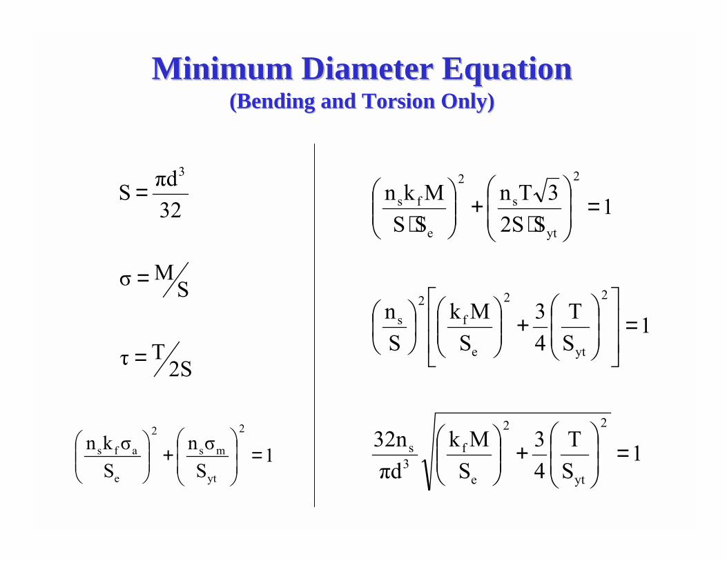
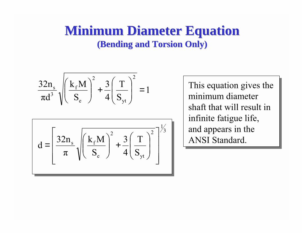
Minimum Diameter EquationMinimum Diameter Equation(Bending and Torsion Only)(Bending and Torsion Only)
2STτ
SMσ
32πdS
3
=
=
=
1ST
43
SMk
πd32n
1ST
43
SMk
Sn
1S2S
3TnSSMkn
2
yt
2
e
f3s
2
yt
2
e
f2
s
2
yt
s
2
e
fs
=��
�
�
��
�
�+��
�
����
�
=��
�
�
�
��
�
�
��
�
�+��
�
����
���
���
�
=��
�
�
��
�
�
⋅+��
�
����
�
⋅
1Sσn
Sσkn
2
yt
ms
2
e
afs =��
�
�
��
�
�+��
�
����
�
Minimum Diameter EquationMinimum Diameter Equation(Bending and Torsion Only)(Bending and Torsion Only)
31
2
yt
2
e
fs
2
yt
2
e
f3s
ST
43
SMk
π32nd
1ST
43
SMk
πd32n
���
�
�
���
�
�
��
�
�
�+��
�
�
�=
=��
�
�
�+��
�
�
� This equation gives the minimum diameter shaft that will result in infinite fatigue life, and appears in the ANSI Standard.
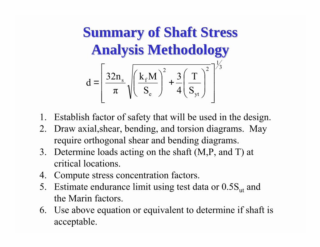
Summary of Shaft Stress Summary of Shaft Stress Analysis MethodologyAnalysis Methodology
31
2
yt
2
e
fs
ST
43
SMk
π32nd
���
�
�
���
�
�
��
�
�
�+��
�
�
�=
1. Establish factor of safety that will be used in the design.2. Draw axial,shear, bending, and torsion diagrams. May
require orthogonal shear and bending diagrams.3. Determine loads acting on the shaft (M,P, and T) at
critical locations.4. Compute stress concentration factors.5. Estimate endurance limit using test data or 0.5Sut and
the Marin factors.6. Use above equation or equivalent to determine if shaft is
acceptable.
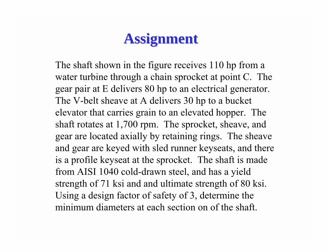
AssignmentAssignment
The shaft shown in the figure receives 110 hp from a water turbine through a chain sprocket at point C. The gear pair at E delivers 80 hp to an electrical generator. The V-belt sheave at A delivers 30 hp to a bucket elevator that carries grain to an elevated hopper. The shaft rotates at 1,700 rpm. The sprocket, sheave, and gear are located axially by retaining rings. The sheave and gear are keyed with sled runner keyseats, and there is a profile keyseat at the sprocket. The shaft is made from AISI 1040 cold-drawn steel, and has a yield strength of 71 ksi and and ultimate strength of 80 ksi. Using a design factor of safety of 3, determine the minimum diameters at each section on of the shaft.
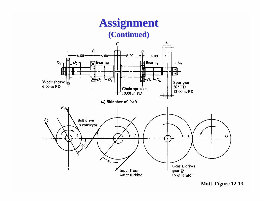
AssignmentAssignment(Continued)(Continued)
Mott, Figure 12-13