BE -6 BODY ELECTRICAL SYSTEM AUDIO S YSTEM€¦ · be -6 body electrical system audio s ystem...
43
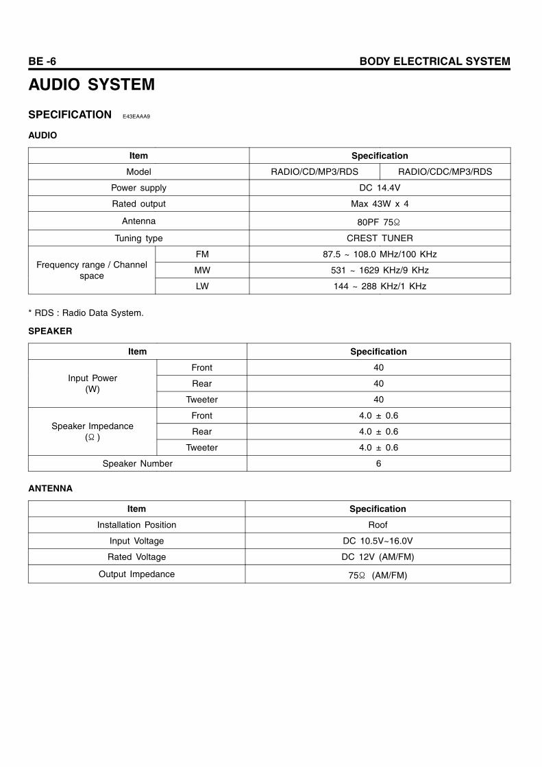
BE -6 BODY ELECTRICAL SYSTEM AUDIO SYSTEM SPECIFICATION E43EAAA9 AUDIO Item Specification Model RADIO/CD/MP3/RDS RADIO/CDC/MP3/RDS Power supply DC 14.4V Rated output Max 43W x 4 Antenna 80PF 75Ω Tuning type CREST TUNER FM 87.5 ~ 108.0 MHz/100 KHz MW 531 ~ 1629 KHz/9 KHz Frequency range / Channel space LW 144 ~ 288 KHz/1 KHz * RDS : Radio Data System. SPEAKER Item Specification Front 40 Rear 40 Input Power (W) Tweeter 40 Front 4.0 ± 0.6 Rear 4.0 ± 0.6 Speaker Impedance (Ω ) Tweeter 4.0 ± 0.6 Speaker Number 6 ANTENNA Item Specification Installation Position Roof Input Voltage DC 10.5V~16.0V Rated Voltage DC 12V (AM/FM) Output Impedance 75Ω (AM/FM)
Transcript of BE -6 BODY ELECTRICAL SYSTEM AUDIO S YSTEM€¦ · be -6 body electrical system audio s ystem...
BE -6 BODY ELECTRICAL SYSTEM
AUDIO SYSTEM
SPECIFICATION E43EAAA9
AUDIO
Item Specification
Model RADIO/CD/MP3/RDS RADIO/CDC/MP3/RDS
Power supply DC 14.4V
Rated output Max 43W x 4
Antenna 80PF 75Ω
Tuning type CREST TUNER
FM 87.5 ~ 108.0 MHz/100 KHz
MW 531 ~ 1629 KHz/9 KHzFrequency range / Channel
spaceLW 144 ~ 288 KHz/1 KHz
* RDS : Radio Data System.
SPEAKER
Item Specification
Front 40
Rear 40Input Power
(W)Tweeter 40
Front 4.0 ± 0.6
Rear 4.0 ± 0.6Speaker Impedance
(Ω )Tweeter 4.0 ± 0.6
Speaker Number 6
ANTENNA
Item Specification
Installation Position Roof
Input Voltage DC 10.5V~16.0V
Rated Voltage DC 12V (AM/FM)
Output Impedance 75Ω (AM/FM)
AUDIO SYSTEM BE -7
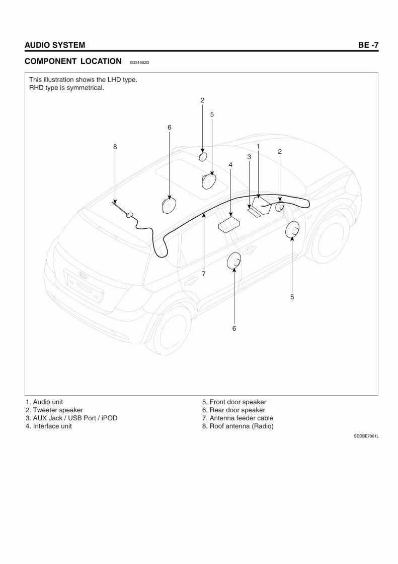
COMPONENT LOCATION ED31662D
5
1
43
2
2
6
8
5
6
7
1. Audio unit2. Tweeter speaker3. AUX Jack / USB Port / iPOD4. Interface unit
5. Front door speaker6. Rear door speaker7. Antenna feeder cable8. Roof antenna (Radio)
This illustration shows the LHD type.RHD type is symmetrical.
SEDBE7001L
BE -8 BODY ELECTRICAL SYSTEM
AUDIO UNIT
COMPONENTS EF07D72E
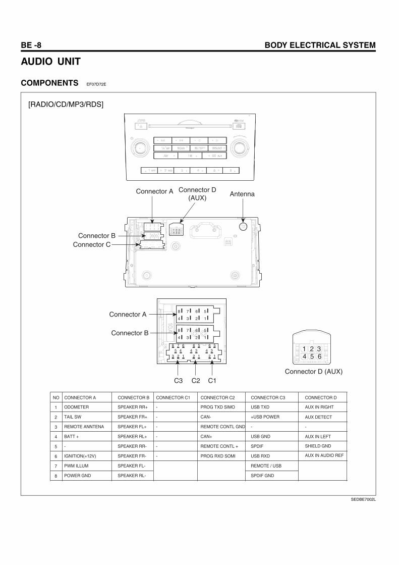
[RADIO/CD/MP3/RDS]
Connector A Connector D(AUX)
Connector D (AUX)
Connector BConnector C
Connector A
C1C2C3
Connector B
Antenna
4 3 2 1
8
1 2 3654
7 6 5
4 3 2 1
8
8 7 6 6 5 6 5
3 2 1 2 1 2 1
5 4 4 3 4 3
7 6 5
NO CONNECTOR A CONNECTOR B CONNECTOR C1 CONNECTOR C2 CONNECTOR C3 CONNECTOR D
AUX IN RIGHT
AUX DETECT
-
AUX IN LEFT
SHIELD GND
AUX IN AUDIO REF
1 ODOMETER SPEAKER RR+ - PROG TXD SIMO
2 TAIL SW SPEAKER FR+ - CAN-
3 REMOTE ANNTENA SPEAKER FL+ -
USB TXD
+USB POWER
REMOTE CONTL GND
4 BATT + SPEAKER RL+ - CAN+
5 - SPEAKER RR- - REMOTE CONTL +
6 IGNITION(+12V) SPEAKER FR- - PROG RXD SOMI
7 PWM ILLUM SPEAKER FL-
8 POWER GND SPEAKER RL-
-
USB GND
SPDIF
USB RXD
REMOTE / USB
SPDIF GND
1 2 3654
SEDBE7002L
AUDIO SYSTEM BE -9
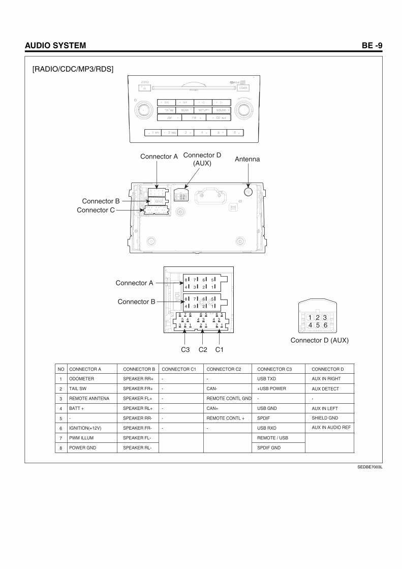
[RADIO/CDC/MP3/RDS]
Connector A
Connector BConnector C
Antenna
Connector A
C1C2C3
Connector B
4 3 2 1
8 7 6 5
4 3 2 1
8
8 7 6 6 5 6 5
3 2 1 2 1 2 1
5 4 4 3 4 3
7 6 5
Connector D(AUX)
2 365
Connector D (AUX)
1 2 3654
NO CONNECTOR A CONNECTOR B CONNECTOR C1 CONNECTOR C2 CONNECTOR C3 CONNECTOR D
AUX IN RIGHT
AUX DETECT
-
AUX IN LEFT
SHIELD GND
AUX IN AUDIO REF
1 ODOMETER SPEAKER RR+ - -
2 TAIL SW SPEAKER FR+ - CAN-
3 REMOTE ANNTENA SPEAKER FL+ -
USB TXD
+USB POWER
REMOTE CONTL GND
4 BATT + SPEAKER RL+ - CAN+
5 - SPEAKER RR- - REMOTE CONTL +
6 IGNITION(+12V) SPEAKER FR- - -
7 PWM ILLUM SPEAKER FL-
8 POWER GND SPEAKER RL-
-
USB GND
SPDIF
USB RXD
REMOTE / USB
SPDIF GND
SEDBE7003L
BE -10 BODY ELECTRICAL SYSTEM
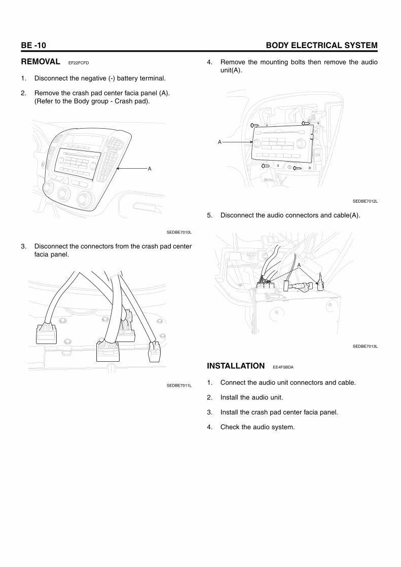
REMOVAL EF22FCFD
1. Disconnect the negative (-) battery terminal.
2. Remove the crash pad center facia panel (A).(Refer to the Body group - Crash pad).
A
SEDBE7010L
3. Disconnect the connectors from the crash pad centerfacia panel.
SEDBE7011L
4. Remove the mounting bolts then remove the audiounit(A).
A
SEDBE7012L
5. Disconnect the audio connectors and cable(A).
A
SEDBE7013L
INSTALLATION EE4F5BDA
1. Connect the audio unit connectors and cable.
2. Install the audio unit.
3. Install the crash pad center facia panel.
4. Check the audio system.
AUDIO SYSTEM BE -11
SPEAKERS
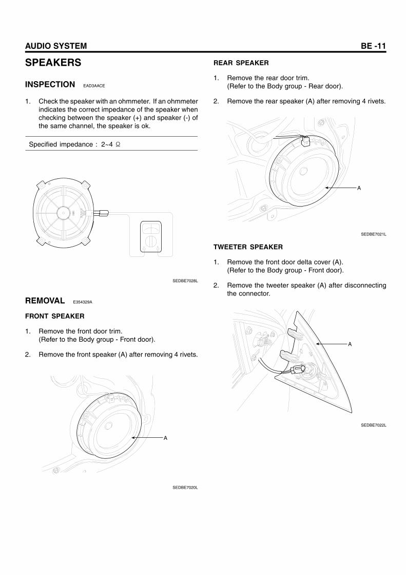
INSPECTION EAD3AACE
1. Check the speaker with an ohmmeter. If an ohmmeterindicates the correct impedance of the speaker whenchecking between the speaker (+) and speaker (-) ofthe same channel, the speaker is ok.
Specified impedance : 2~4 Ω
SEDBE7028L
REMOVAL E354329A
FRONT SPEAKER
1. Remove the front door trim.(Refer to the Body group - Front door).
2. Remove the front speaker (A) after removing 4 rivets.
A
SEDBE7020L
REAR SPEAKER
1. Remove the rear door trim.(Refer to the Body group - Rear door).
2. Remove the rear speaker (A) after removing 4 rivets.
A
SEDBE7021L
TWEETER SPEAKER
1. Remove the front door delta cover (A).(Refer to the Body group - Front door).
2. Remove the tweeter speaker (A) after disconnectingthe connector.
A
SEDBE7022L
BE -12 BODY ELECTRICAL SYSTEM
INSTALLATION EE091CFD
FRONT SPEAKER
1. Install the front speaker.
2. Install the front door trim.
REAR SPEAKER
1. Install the rear speaker.
2. Install the rear door trim.
TWEETER SPEAKER
1. Install the tweeter speaker after connecting thetweeter speaker connector.
2. Install the front door delta cover.
AUDIO SYSTEM BE -13
ANTENNA
INSPECTION E2A6BE3D
ANTENNA CABLE
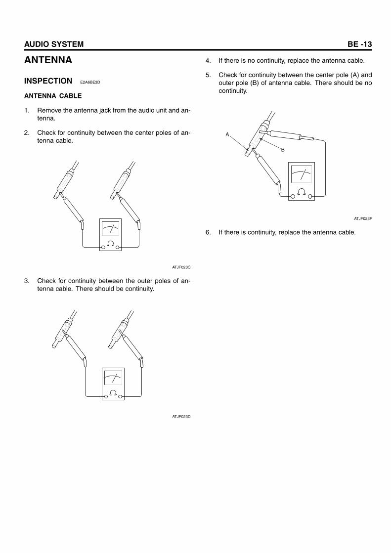
1. Remove the antenna jack from the audio unit and an-tenna.
2. Check for continuity between the center poles of an-tenna cable.
ATJF023C
3. Check for continuity between the outer poles of an-tenna cable. There should be continuity.
ATJF023D
4. If there is no continuity, replace the antenna cable.
5. Check for continuity between the center pole (A) andouter pole (B) of antenna cable. There should be nocontinuity.
A
B
ATJF023F
6. If there is continuity, replace the antenna cable.
BE -14 BODY ELECTRICAL SYSTEM
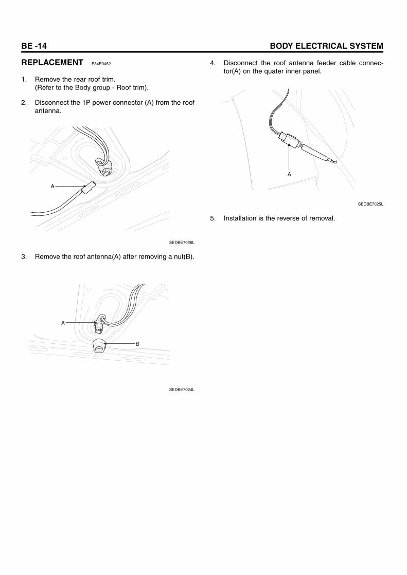
REPLACEMENT E84E0452
1. Remove the rear roof trim.(Refer to the Body group - Roof trim).
2. Disconnect the 1P power connector (A) from the roofantenna.
A
SEDBE7026L
3. Remove the roof antenna(A) after removing a nut(B).
A
B
SEDBE7024L
4. Disconnect the roof antenna feeder cable connec-tor(A) on the quater inner panel.
A
SEDBE7025L
5. Installation is the reverse of removal.
AUDIO SYSTEM BE -15
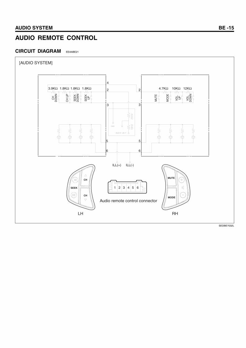
AUDIO REMOTE CONTROL
CIRCUIT DIAGRAM EEAABE21C
HD
OW
N
SE
EK
DO
WN
SE
EK
UP
MU
TE
MO
DE
VOL.
UP
VOL.
DO
WN
CH
UP
3.9KΩ 1.8KΩ 1.8KΩ 1.8KΩ
ILL(+) ILL(-)
4.7KΩ 10KΩ 12KΩ
4
2 2
3
5
6
5
6
3
Audio remote control connector
1 2 3 4 5 6
[AUDIO SYSTEM]
LH RH
CH
SEEK
CH
MUTE
MODE
SEDBE7032L
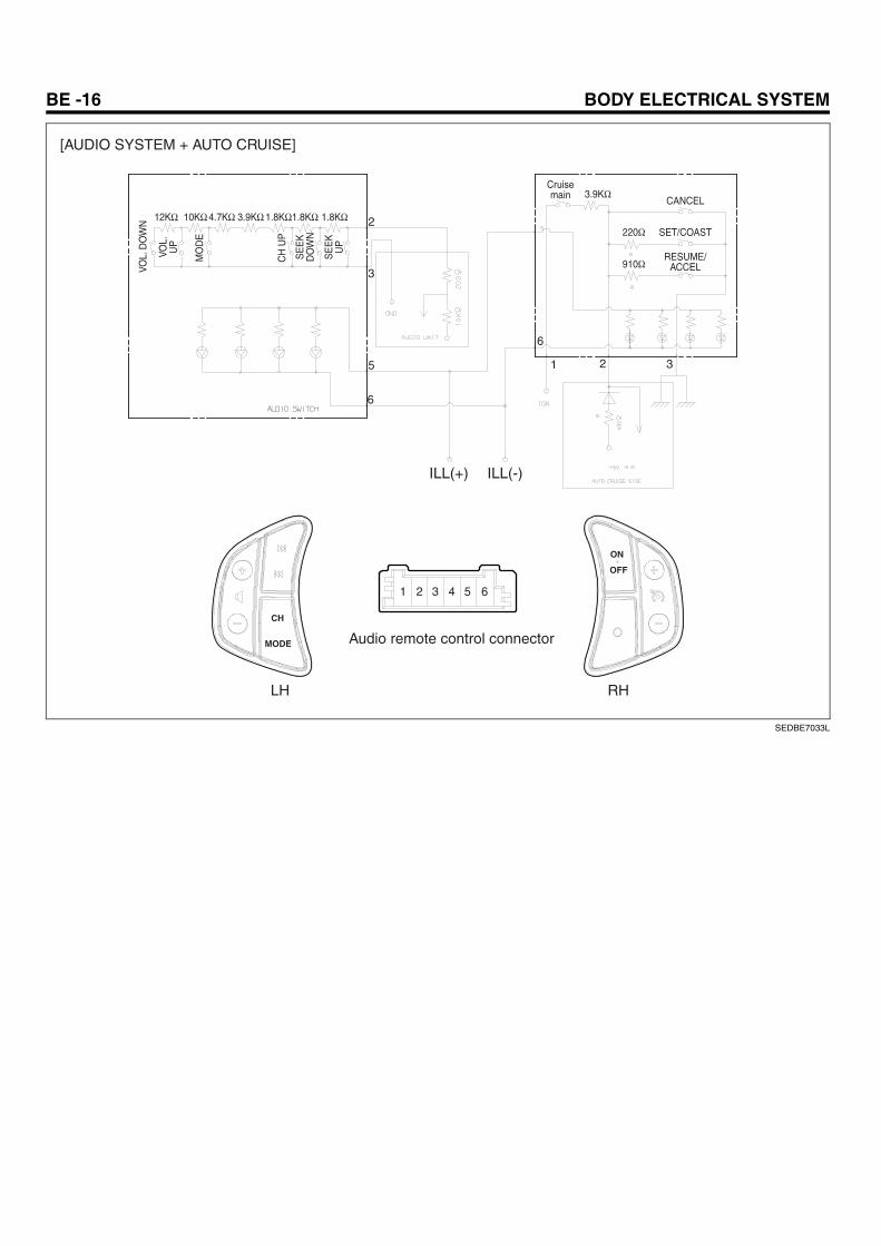
BE -16 BODY ELECTRICAL SYSTEM
VOL.
UP
SE
EK
DO
WN
SE
EK
UP
Cruisemain CANCEL
SET/COAST
RESUME/ACCEL
MO
DE
CH
UP
VOL.
DO
WN
12KΩ 10KΩ 4.7KΩ 3.9KΩ 1.8KΩ1.8KΩ 1.8KΩ
3.9KΩ
220Ω
910Ω
Audio remote control connector
1 2 3 4 5 6
[AUDIO SYSTEM + AUTO CRUISE]
LH RH
ILL(+) ILL(-)
2
3
5
6
1 2 3
6
ON
OFF
CH
MODE
SEDBE7033L
AUDIO SYSTEM BE -17
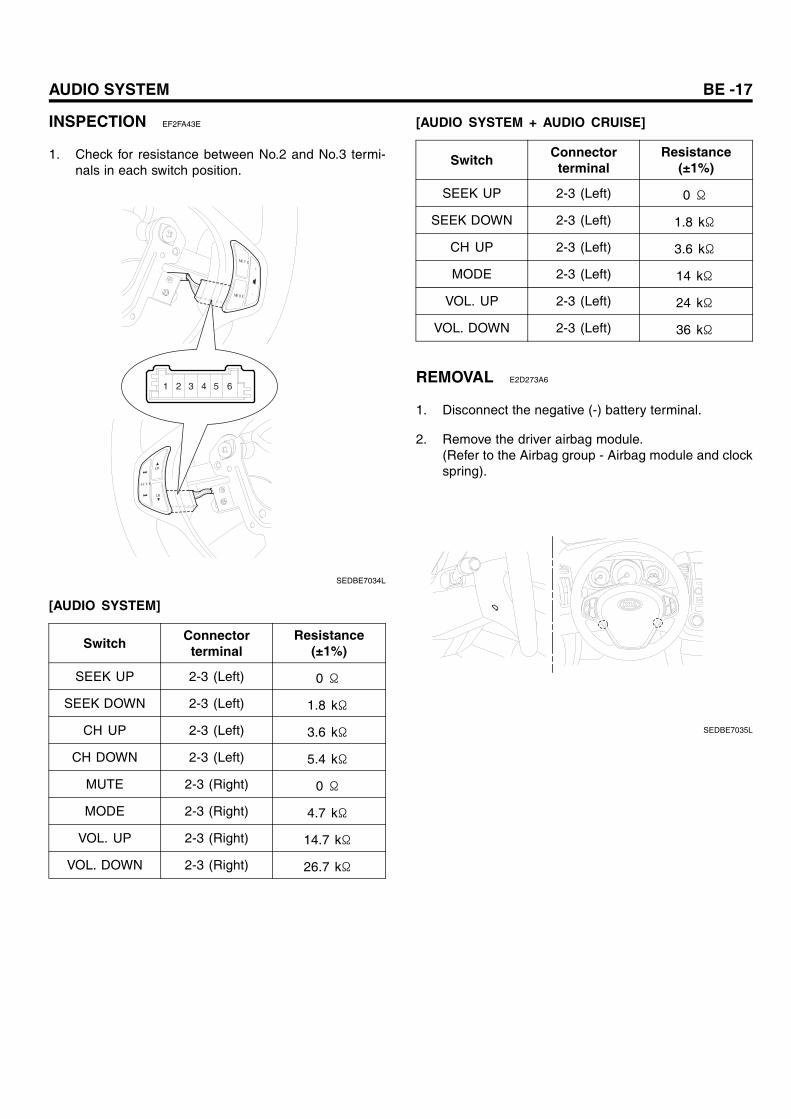
INSPECTION EF2FA43E
1. Check for resistance between No.2 and No.3 termi-nals in each switch position.
MUTE
MODE
CH
CH
SEEK
1 2 3 4 5 6
SEDBE7034L
[AUDIO SYSTEM]
SwitchConnector
terminalResistance
(±1%)
SEEK UP 2-3 (Left) 0 Ω
SEEK DOWN 2-3 (Left) 1.8 kΩ
CH UP 2-3 (Left) 3.6 kΩ
CH DOWN 2-3 (Left) 5.4 kΩ
MUTE 2-3 (Right) 0 Ω
MODE 2-3 (Right) 4.7 kΩ
VOL. UP 2-3 (Right) 14.7 kΩ
VOL. DOWN 2-3 (Right) 26.7 kΩ
[AUDIO SYSTEM + AUDIO CRUISE]
SwitchConnector
terminalResistance
(±1%)
SEEK UP 2-3 (Left) 0 Ω
SEEK DOWN 2-3 (Left) 1.8 kΩ
CH UP 2-3 (Left) 3.6 kΩ
MODE 2-3 (Left) 14 kΩ
VOL. UP 2-3 (Left) 24 kΩ
VOL. DOWN 2-3 (Left) 36 kΩ
REMOVAL E2D273A6
1. Disconnect the negative (-) battery terminal.
2. Remove the driver airbag module.(Refer to the Airbag group - Airbag module and clockspring).
SEDBE7035L
BE -18 BODY ELECTRICAL SYSTEM
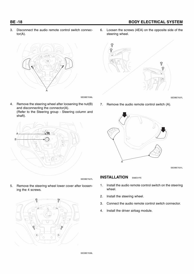
3. Disconnect the audio remote control switch connec-tor(A).
A
SEDBE7036L
4. Remove the steering wheel after loosening the nut(B)and disconnecting the connector(A).(Refer to the Steering group - Steering column andshaft).
A
B
SEDBE7027L
5. Remove the steering wheel lower cover after loosen-ing the 4 screws.
SEDBE7039L
6. Loosen the screws (4EA) on the opposite side of thesteering wheel.
SEDBE7037L
7. Remove the audio remote control switch (A).
MUTE
MODE
SEEKCH
CH
A
SEDBE7031L
INSTALLATION E66E01FE
1. Install the audio remote control switch on the steeringwheel.
2. Install the steering wheel.
3. Connect the audio remote control switch connector.
4. Install the driver airbag module.
AUDIO SYSTEM BE -19
AUX(AUXILIARY)
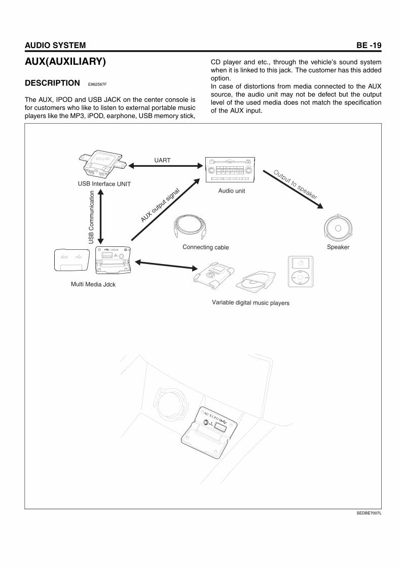
DESCRIPTION E962567F
The AUX, IPOD and USB JACK on the center console isfor customers who like to listen to external portable musicplayers like the MP3, iPOD, earphone, USB memory stick,
CD player and etc., through the vehicle’s sound systemwhen it is linked to this jack. The customer has this addedoption.In case of distortions from media connected to the AUXsource, the audio unit may not be defect but the outputlevel of the used media does not match the specificationof the AUX input.
AUX output signal Audio unit
Connecting cable Speaker
USB Interface UNIT
UART
US
B C
omm
unic
atio
n
Multi Media Jdck
Variable digital music players
AUX IPOD
IPOD AUX
SEDBE7007L
BE -20 BODY ELECTRICAL SYSTEM
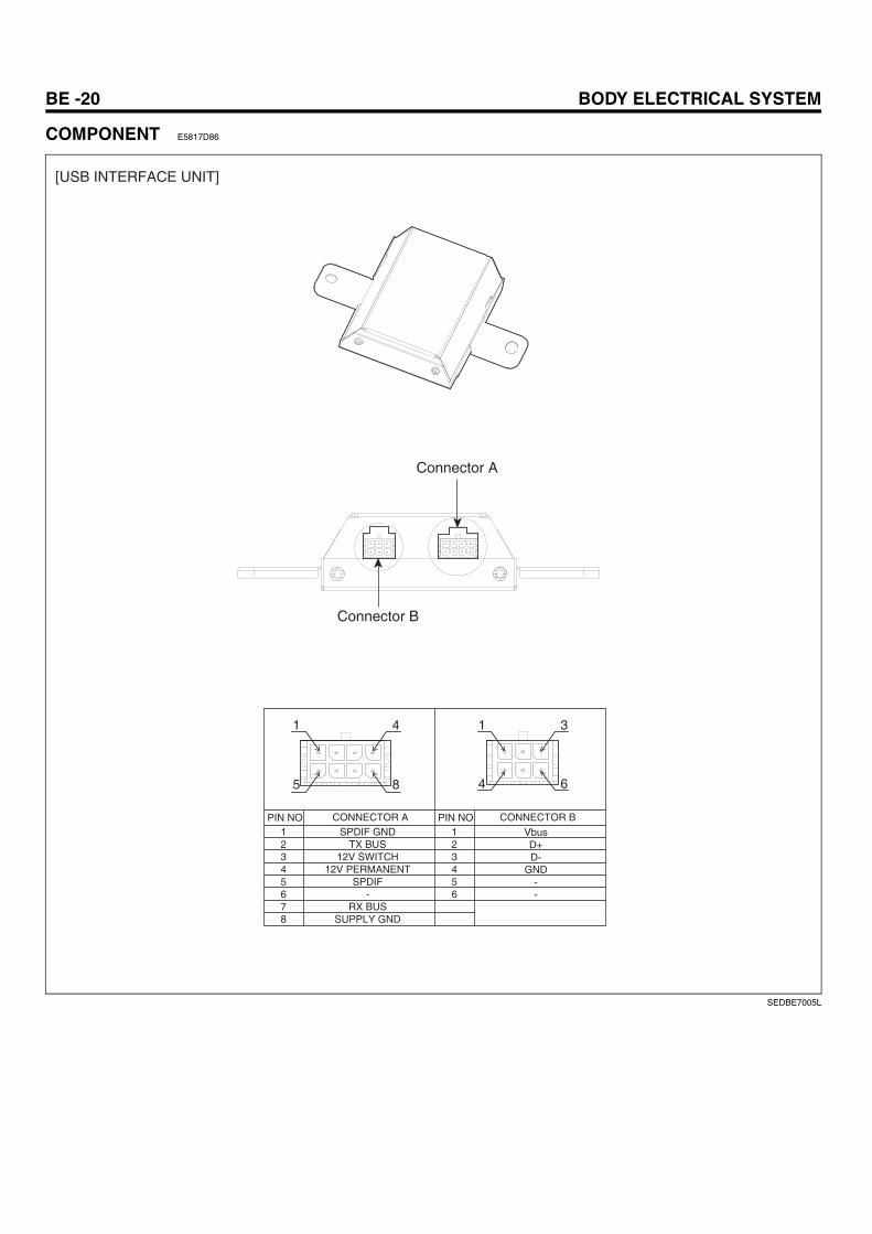
COMPONENT E5817D86
SPDIF GNDTX BUS
12V SWITCH12V PERMANENT
SPDIF-
RX BUSSUPPLY GND
12345678
123456
VbusD+D-
GND--
CONNECTOR APIN NO PIN NO CONNECTOR B
[USB INTERFACE UNIT]
Connector A
Connector B
1 4
5 8
1 3
4 6
SEDBE7005L
AUDIO SYSTEM BE -21
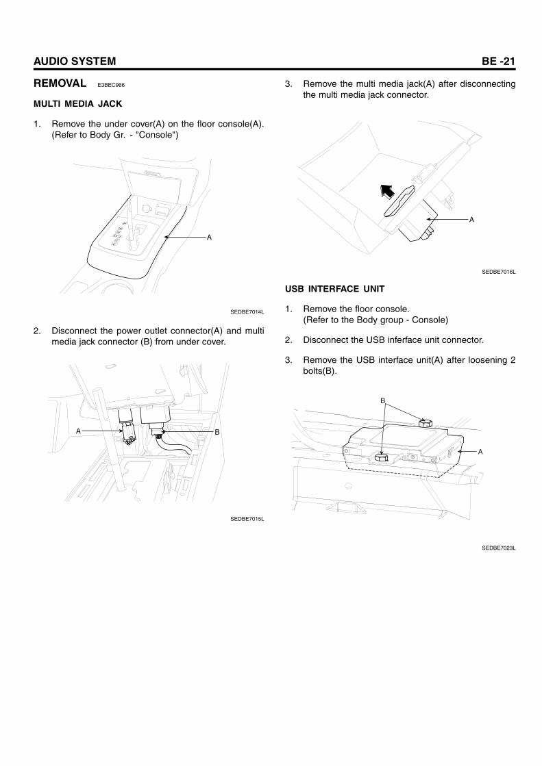
REMOVAL E3BEC966
MULTI MEDIA JACK
1. Remove the under cover(A) on the floor console(A).(Refer to Body Gr. - "Console")
P
R
ND 3
2L
A
SEDBE7014L
2. Disconnect the power outlet connector(A) and multimedia jack connector (B) from under cover.
BA
SEDBE7015L
3. Remove the multi media jack(A) after disconnectingthe multi media jack connector.
A
SEDBE7016L
USB INTERFACE UNIT
1. Remove the floor console.(Refer to the Body group - Console)
2. Disconnect the USB inferface unit connector.
3. Remove the USB interface unit(A) after loosening 2bolts(B).
A
B
SEDBE7023L
BE -22 BODY ELECTRICAL SYSTEM
INSTALLATION EE6F198A
MULTI MEDIA JACK
1. Install the multi media jack.
2. Connect the multi media jack connector.
3. Install the under cover to the floor console.
USB INTERFACE UNIT
1. Install the USB interface unit.
2. Connect the USB interface unit connector.
3. Install the floor console.
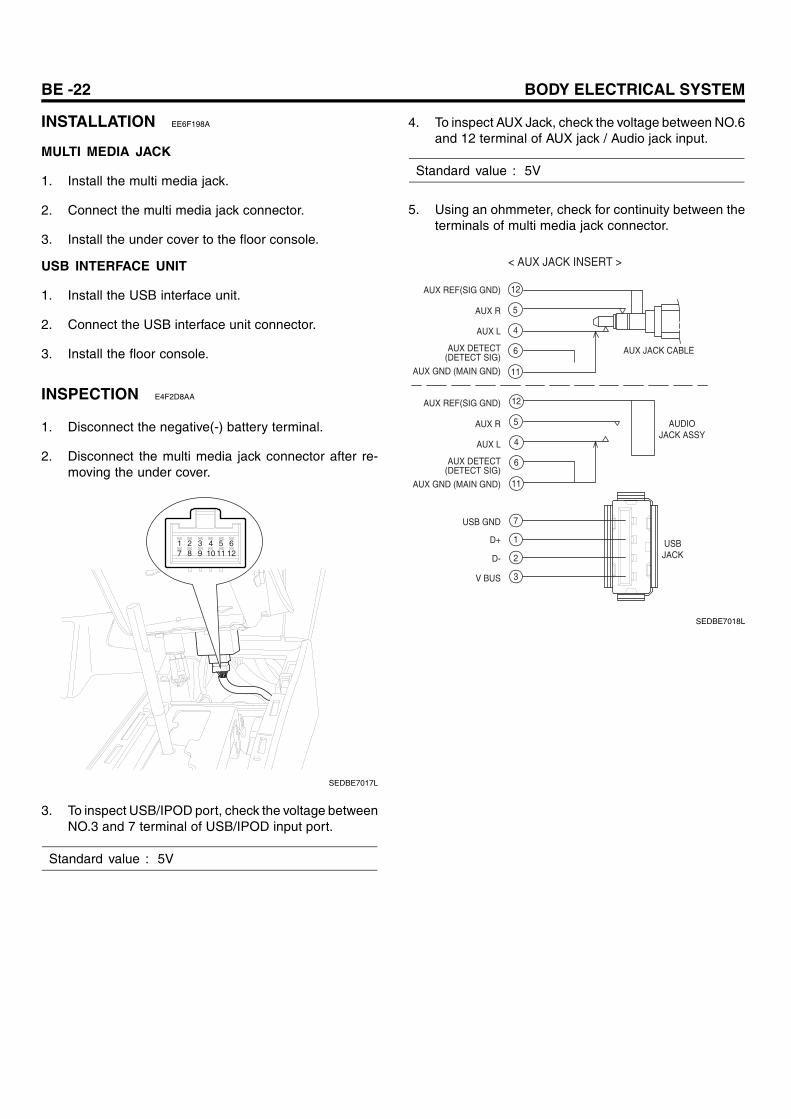
INSPECTION E4F2D8AA
1. Disconnect the negative(-) battery terminal.
2. Disconnect the multi media jack connector after re-moving the under cover.
1 2 3 4 5 67 8 9 10 11 12
SEDBE7017L
3. To inspect USB/IPOD port, check the voltage betweenNO.3 and 7 terminal of USB/IPOD input port.
Standard value : 5V
4. To inspect AUX Jack, check the voltage between NO.6and 12 terminal of AUX jack / Audio jack input.
Standard value : 5V
5. Using an ohmmeter, check for continuity between theterminals of multi media jack connector.
AUDIOJACK ASSY
AUX JACK CABLE
< AUX JACK INSERT >
AUX REF(SIG GND)
AUX R
AUX L
AUX DETECT(DETECT SIG)
AUX GND (MAIN GND)
AUX REF(SIG GND)
AUX R
AUX L
AUX DETECT(DETECT SIG)
AUX GND (MAIN GND)
USB GND
V BUS
D-
D+
12
4
5
6
11
12
4
5
6
11
7
1
2
3
USBJACK
SEDBE7018L
AUDIO SYSTEM BE -23
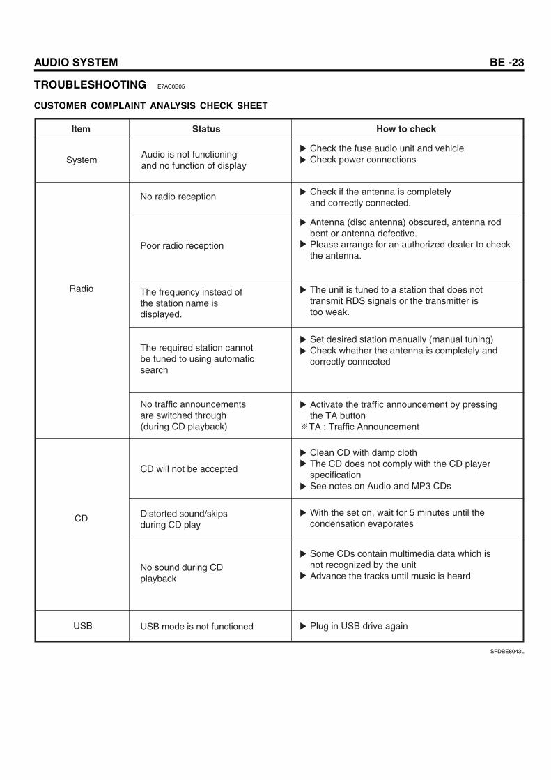
TROUBLESHOOTING E7AC0B05
CUSTOMER COMPLAINT ANALYSIS CHECK SHEET
Item Status How to check
SystemAudio is not functioning and no function of display
No radio reception
Poor radio reception
The frequency instead ofthe station name isdisplayed.
The required station cannot be tuned to using automaticsearch
No traffic announcementsare switched through(during CD playback)
CD will not be accepted
Distorted sound/skipsduring CD play
No sound during CDplayback
USB mode is not functioned
Radio
CD
USB
Check the fuse audio unit and vehicle Check power connections
Set desired station manually (manual tuning) Check whether the antenna is completely and correctly connected
Clean CD with damp cloth The CD does not comply with the CD player specification See notes on Audio and MP3 CDs
With the set on, wait for 5 minutes until the condensation evaporates
Some CDs contain multimedia data which is not recognized by the unit Advance the tracks until music is heard
Plug in USB drive again
Antenna (disc antenna) obscured, antenna rod bent or antenna defective. Please arrange for an authorized dealer to check the antenna.
Check if the antenna is completely and correctly connected.
The unit is tuned to a station that does not transmit RDS signals or the transmitter is too weak.
Activate the traffic announcement by pressing the TA button
TA : Traffic Announcement
SFDBE8043L
BE -24 BODY ELECTRICAL SYSTEM
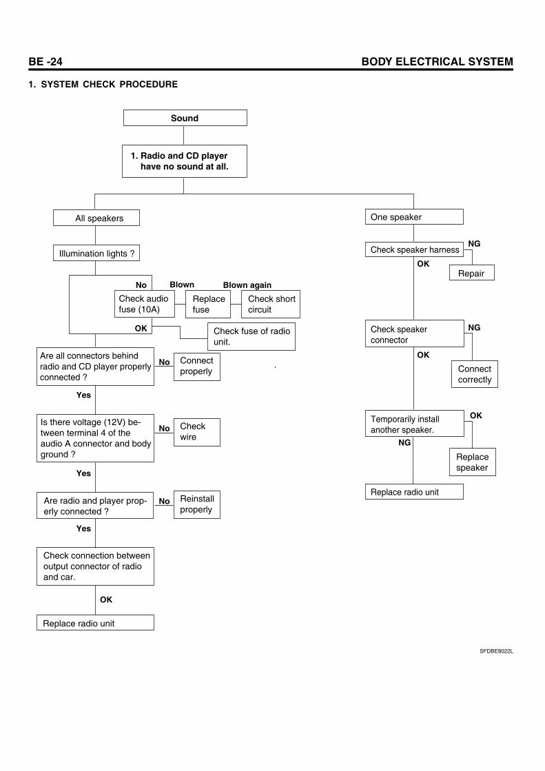
1. SYSTEM CHECK PROCEDURE
Sound
1. Radio and CD player have no sound at all.
All speakers
Illumination lights ?
Check audiofuse (10A)
Are all connectors behindradio and CD player properlyconnected ?
Is there voltage (12V) be-tween terminal 4 of theaudio A connector and body ground ?
Are radio and player prop-erly connected ?
Check connection betweenoutput connector of radio and car.
Replace radio unit
Connectproperly
Checkwire
Reinstallproperly
Replacefuse
Check shortcircuit
Check fuse of radiounit.
No
Yes
Yes
Yes
No
No
No
Blown Blown again
One speaker
Check speaker harness
Replace radio unit
Check speakerconnector
Temporarily installanother speaker.
Repair
Connectcorrectly
Replacespeaker
OK
OK
OK
OK
OK
NG
NG
NG
SFDBE8022L
AUDIO SYSTEM BE -25
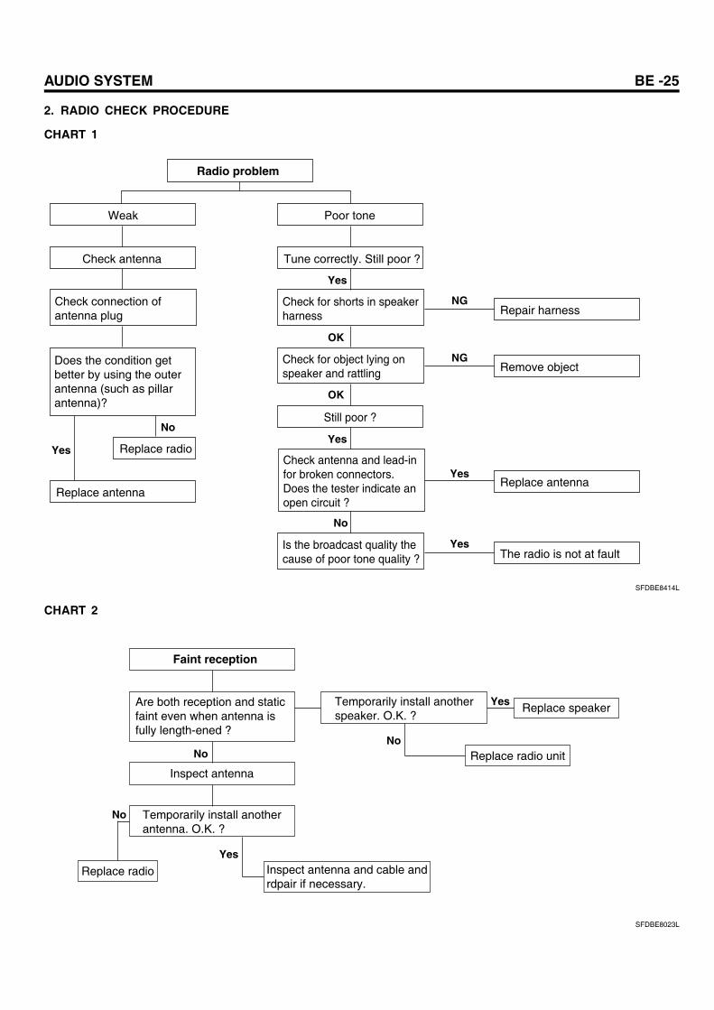
2. RADIO CHECK PROCEDURE
CHART 1
Radio problem
Weak Poor tone
Tune correctly. Still poor ?
Check for shorts in speakerharness
Check for object lying onspeaker and rattling
Still poor ?
Check antenna and lead-infor broken connectors.Does the tester indicate anopen circuit ?
Is the broadcast quality thecause of poor tone quality ?
Repair harness
Remove object
Replace antennaYes
YesThe radio is not at fault
Check antenna
Check connection ofantenna plug
Does the condition getbetter by using the outerantenna (such as pillarantenna)?
Replace antenna
Replace radio
No
Yes
Yes
OK
OK
Yes
No
NG
NG
SFDBE8414L
CHART 2
Faint reception
Are both reception and static faint even when antenna is fully length-ened ?
Temporarily install anotherspeaker. O.K. ?
Replace speaker
Replace radio unit
Yes
No
Inspect antenna
Temporarily install anotherantenna. O.K. ?
Inspect antenna and cable andrdpair if necessary.
Yes
No
No
Replace radio
SFDBE8023L
BE -26 BODY ELECTRICAL SYSTEM
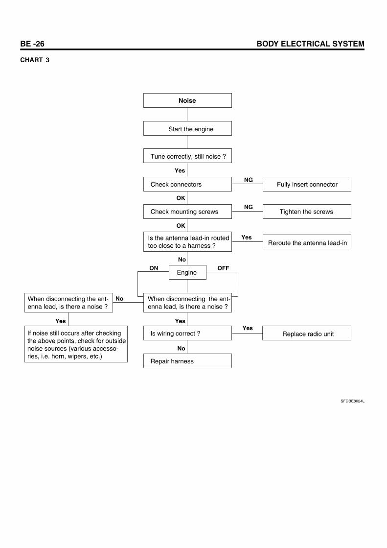
CHART 3
Noise
Start the engine
Tune correctly, still noise ?
Check connectors
Check mounting screws
Is the antenna lead-in routedtoo close to a harness ?
Engine
When disconnecting the ant-enna lead, is there a noise ?
Is wiring correct ?
Repair harness
Fully insert connector
Tighten the screws
Reroute the antenna lead-in
Replace radio unit
When disconnecting the ant-enna lead, is there a noise ?
If noise still occurs after checkingthe above points, check for outsidenoise sources (various accesso-ries, i.e. horn, wipers, etc.)
Yes
Yes
Yes
NoON OFF
No
Yes
No
Yes
NG
NG
OK
OK
SFDBE8024L
AUDIO SYSTEM BE -27
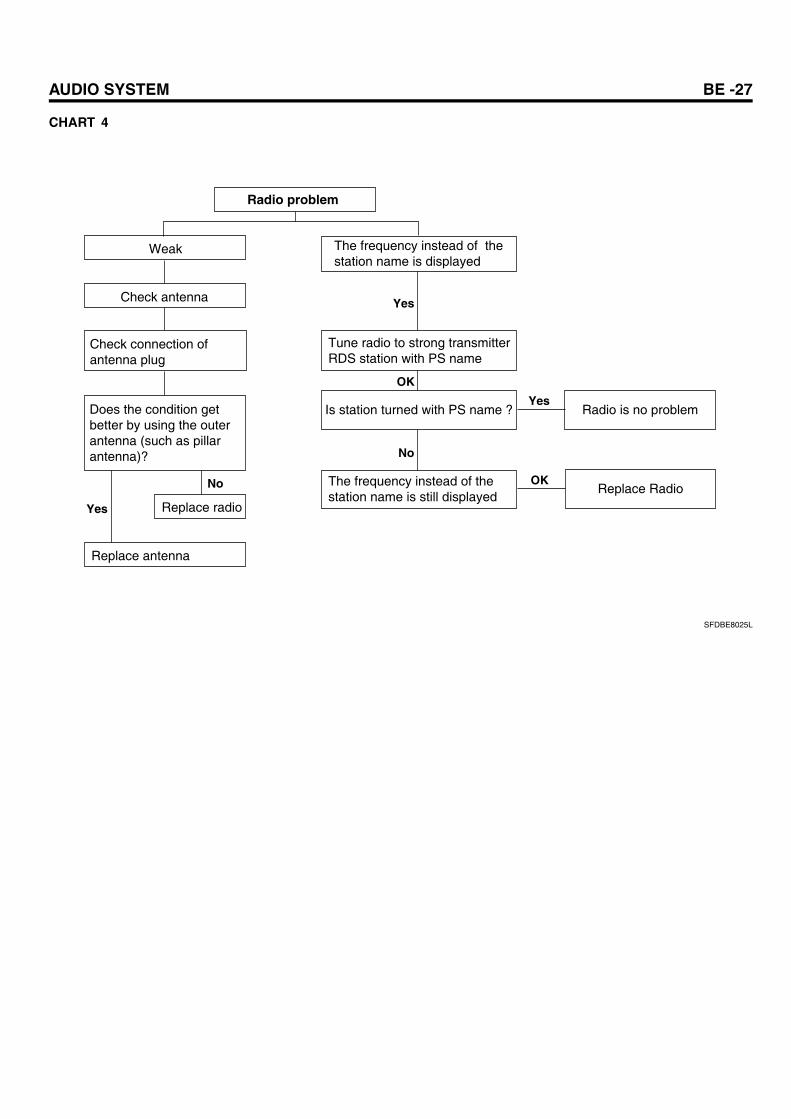
CHART 4
Radio problem
Weak The frequency instead of thestation name is displayed
Tune radio to strong transmitterRDS station with PS name
The frequency instead of thestation name is still displayed
Is station turned with PS name ? Radio is no problem
Check antenna
Check connection ofantenna plug
Replace Radio
Does the condition getbetter by using the outerantenna (such as pillarantenna)?
Replace antenna
Replace radio
No
No
OK
OK
Yes
Yes
Yes
SFDBE8025L
BE -28 BODY ELECTRICAL SYSTEM
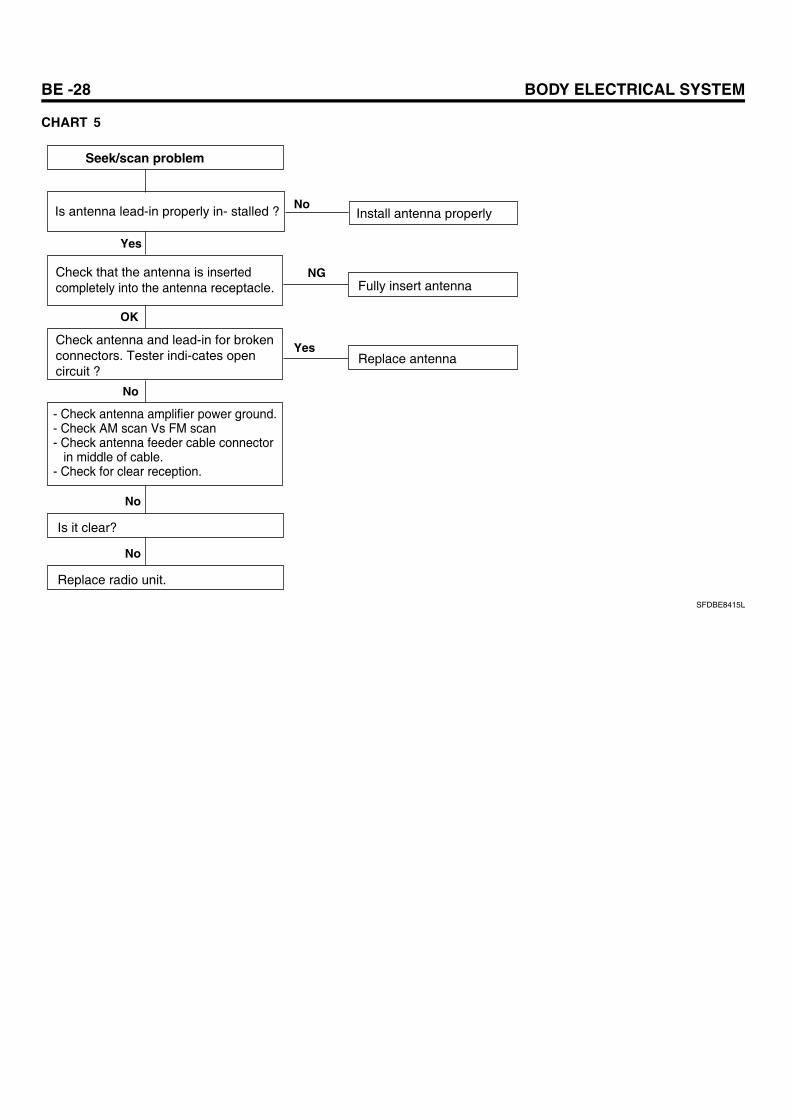
CHART 5
Seek/scan problem
Is antenna lead-in properly in- stalled ?
Check that the antenna is inserted completely into the antenna receptacle.
Check antenna and lead-in for broken connectors. Tester indi-cates open circuit ?
Install antenna properly
Fully insert antenna
Replace antenna
Yes
No
Yes
- Check antenna amplifier power ground.- Check AM scan Vs FM scan- Check antenna feeder cable connector in middle of cable.- Check for clear reception.
Is it clear?
No
No
Replace radio unit.
No
NG
OK
SFDBE8415L
AUDIO SYSTEM BE -29
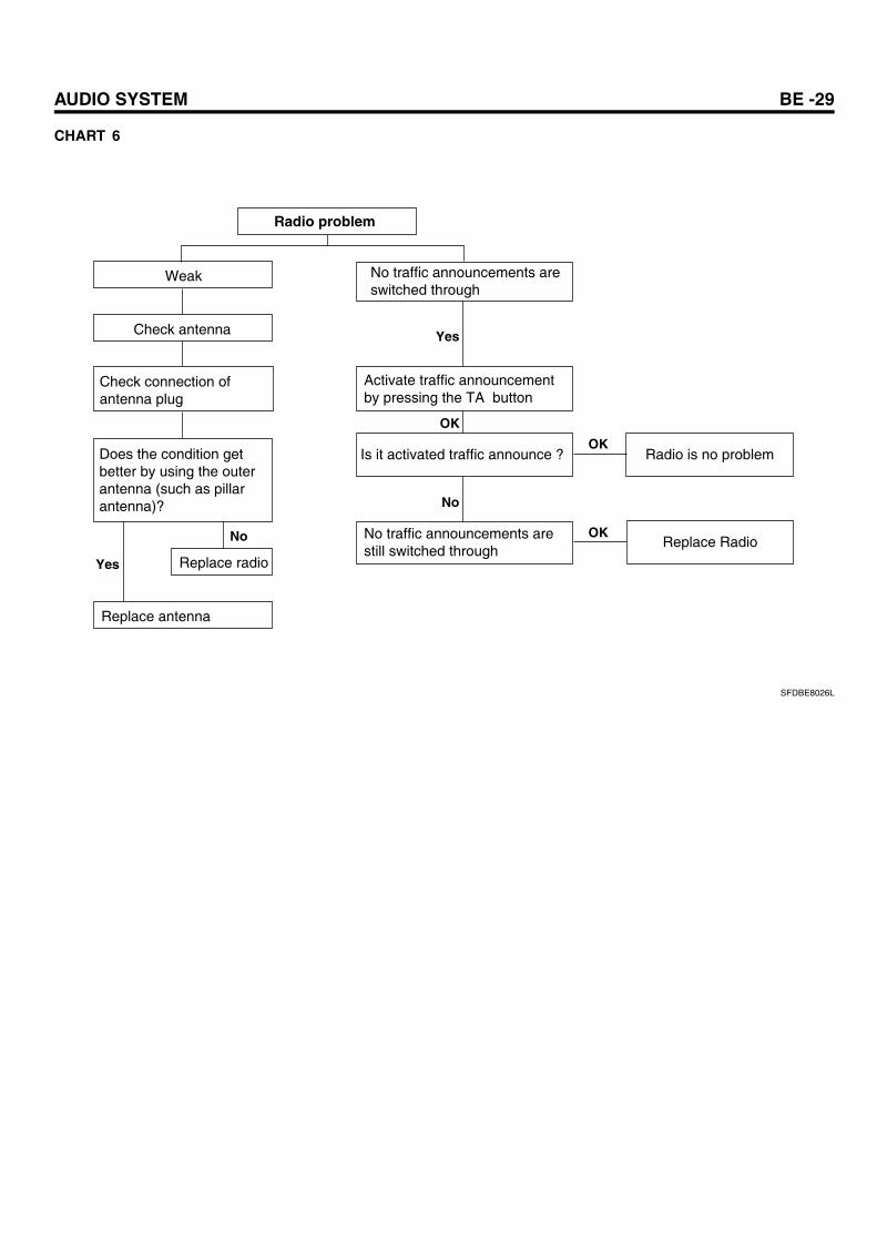
CHART 6
Radio problem
Weak No traffic announcements areswitched through
Activate traffic announcementby pressing the TA button
No traffic announcements arestill switched through
Is it activated traffic announce ? Radio is no problem
Check antenna
Check connection ofantenna plug
Replace Radio
Does the condition getbetter by using the outerantenna (such as pillarantenna)?
Replace antenna
Replace radio
No
No
OK
OK
OK
Yes
Yes
SFDBE8026L
BE -30 BODY ELECTRICAL SYSTEM
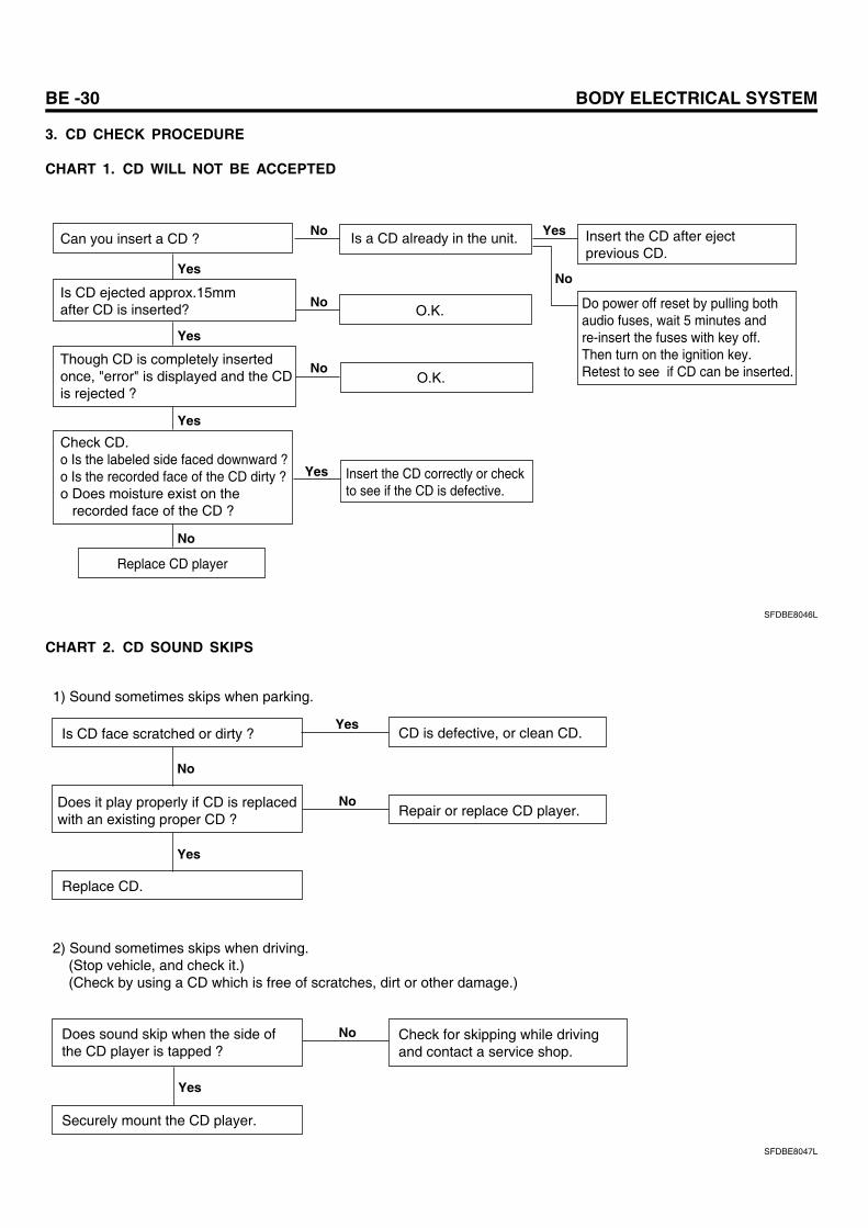
3. CD CHECK PROCEDURE
CHART 1. CD WILL NOT BE ACCEPTED
Can you insert a CD ?
Is CD ejected approx.15mm after CD is inserted?
Though CD is completely insertedonce, "error" is displayed and the CDis rejected ?
Check CD.o Is the labeled side faced downward ?o Is the recorded face of the CD dirty ?o Does moisture exist on the recorded face of the CD ?
Replace CD player
Is a CD already in the unit.
O.K.
O.K.
Insert the CD correctly or checkto see if the CD is defective.
Yes
Yes
Yes
Yes
No
No Insert the CD after eject previous CD.
Yes
Do power off reset by pulling bothaudio fuses, wait 5 minutes andre-insert the fuses with key off.Then turn on the ignition key. Retest to see if CD can be inserted.
No
No
No
SFDBE8046L
CHART 2. CD SOUND SKIPS
CD is defective, or clean CD.Is CD face scratched or dirty ?
No
1) Sound sometimes skips when parking.
Does it play properly if CD is replacedwith an existing proper CD ?
Yes
Replace CD.
No
Yes
Repair or replace CD player.
2) Sound sometimes skips when driving. (Stop vehicle, and check it.) (Check by using a CD which is free of scratches, dirt or other damage.)
Does sound skip when the side of the CD player is tapped ?
Yes
No Check for skipping while driving and contact a service shop.
Securely mount the CD player.
SFDBE8047L
AUDIO SYSTEM BE -31
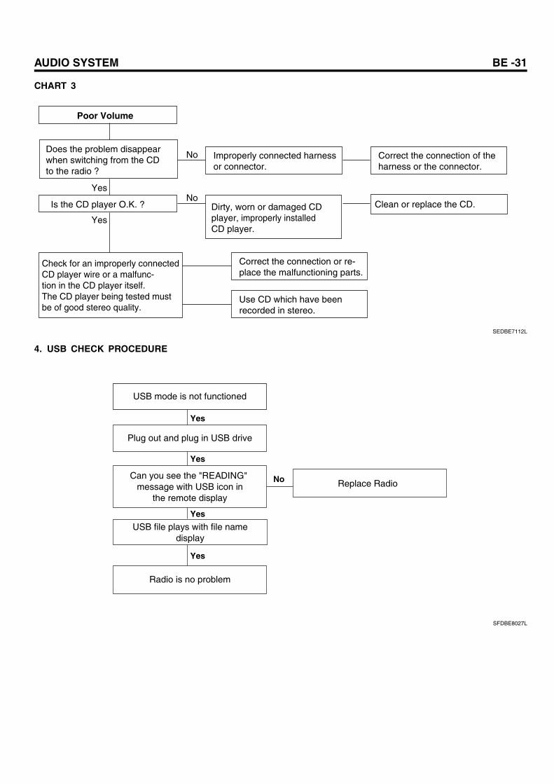
CHART 3
Poor Volume
Does the problem disappearwhen switching from the CDto the radio ?
Is the CD player O.K. ?
Check for an improperly connected CD player wire or a malfunc-tion in the CD player itself.The CD player being tested mustbe of good stereo quality.
Improperly connected harnessor connector.
Correct the connection of theharness or the connector.
Clean or replace the CD.Dirty, worn or damaged CDplayer, improperly installedCD player.
Correct the connection or re-place the malfunctioning parts.
Use CD which have beenrecorded in stereo.
Yes
Yes
No
No
SEDBE7112L
4. USB CHECK PROCEDURE
USB mode is not functioned
USB file plays with file namedisplay
Yes
Yes
Yes
Yes
Plug out and plug in USB drive
Can you see the "READING" message with USB icon in
the remote display
Radio is no problem
Replace RadioNo
SFDBE8027L
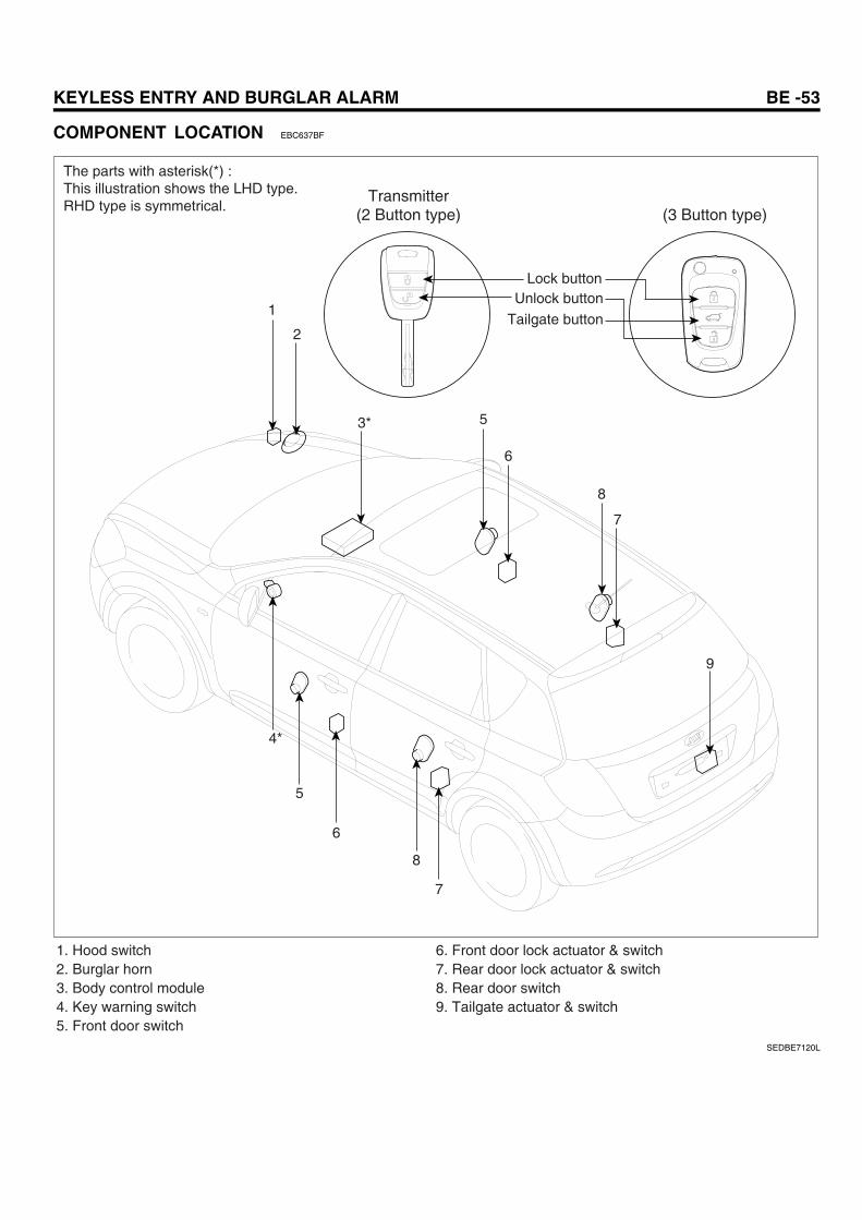
KEYLESS ENTRY AND BURGLAR ALARM BE -53
COMPONENT LOCATION EBC637BF
2
5
6
8
7
5
6
8
7
1
3*
4*
9
Transmitter(2 Button type) (3 Button type)
Lock buttonUnlock button
Tailgate button
1. Hood switch2. Burglar horn3. Body control module4. Key warning switch5. Front door switch
6. Front door lock actuator & switch 7. Rear door lock actuator & switch 8. Rear door switch 9. Tailgate actuator & switch
The parts with asterisk(*) :This illustration shows the LHD type.RHD type is symmetrical.
SEDBE7120L
BE -76 BODY ELECTRICAL SYSTEM
TRANSMITTER
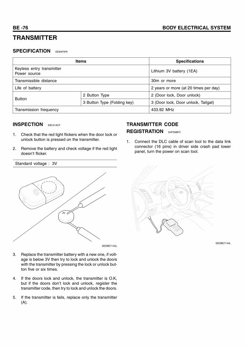
SPECIFICATION EE9AF5FA
Items Specifications
Keyless entry transmitterPower source
Lithium 3V battery (1EA)
Transmissible distance 30m or more
Life of battery 2 years or more (at 20 times per day)
2 Button Type 2 (Door lock, Door unlock)Button
3 Button Type (Folding key) 3 (Door lock, Door unlock, Tailgat)
Transmission frequency 433.92 MHz
INSPECTION E8C31ACF
1. Check that the red light flickers when the door lock orunlock button is pressed on the transmitter.
2. Remove the battery and check voltage if the red lightdoesn’t flicker.
Standard voltage : 3V
SEDBE7142L
3. Replace the transmitter battery with a new one, if volt-age is below 3V then try to lock and unlock the doorswith the transmitter by pressing the lock or unlock but-ton five or six times.
4. If the doors lock and unlock, the transmitter is O.K,but if the doors don’t lock and unlock, register thetransmitter code, then try to lock and unlock the doors.
5. If the transmitter is fails, replace only the transmitter(A).
TRANSMITTER CODEREGISTRATION E4FD6BFC
1. Connect the DLC cable of scan tool to the data linkconnector (16 pins) in driver side crash pad lowerpanel, turn the power on scan tool.
SEDBE7144L
IMMOBILIZER CONTROL SYSTEM BE -225
IMMOBILIZER CONTROLSYSTEM
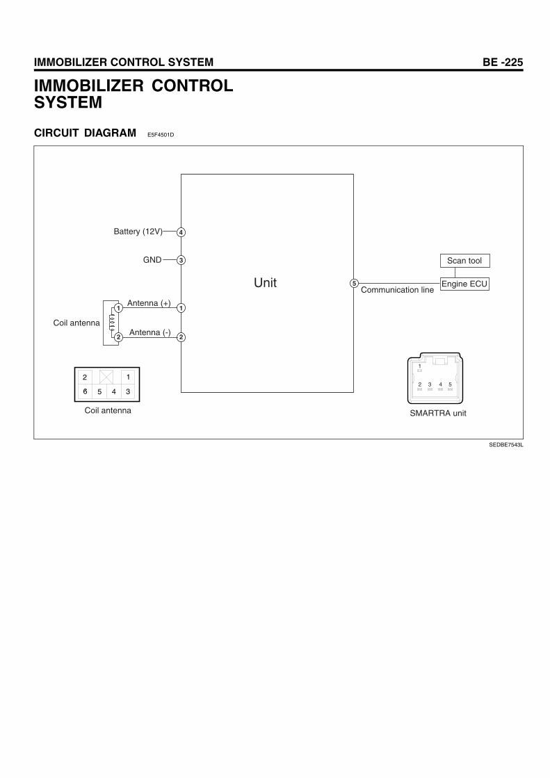
CIRCUIT DIAGRAM E5F4501D
Battery (12V)
GND
Antenna (+)
Coil antennaAntenna (-)
Communication lineUnit Engine ECU
2 1
6 5 4 3
Coil antenna SMARTRA unit
Scan tool
5
4
3
1
2
1
2
1
2 3 4 5
SEDBE7543L
BE -226 BODY ELECTRICAL SYSTEM
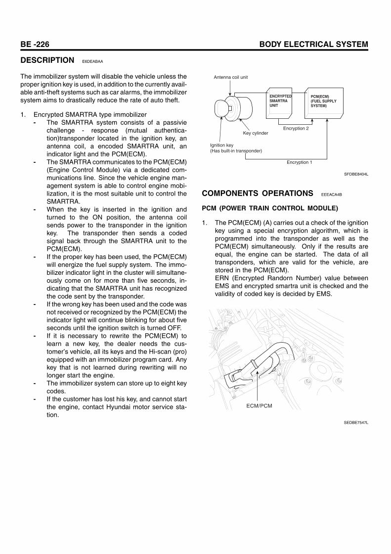
DESCRIPTION E6DEABAA
The immobilizer system will disable the vehicle unless theproper ignition key is used, in addition to the currently avail-able anti-theft systems such as car alarms, the immobilizersystem aims to drastically reduce the rate of auto theft.
1. Encrypted SMARTRA type immobilizer- The SMARTRA system consists of a passivie
challenge - response (mutual authentica-tion)transponder located in the ignition key, anantenna coil, a encoded SMARTRA unit, anindicator light and the PCM(ECM).
- The SMARTRA communicates to the PCM(ECM)(Engine Control Module) via a dedicated com-munications line. Since the vehicle engine man-agement system is able to control engine mobi-lization, it is the most suitable unit to control theSMARTRA.
- When the key is inserted in the ignition andturned to the ON position, the antenna coilsends power to the transponder in the ignitionkey. The transponder then sends a codedsignal back through the SMARTRA unit to thePCM(ECM).
- If the proper key has been used, the PCM(ECM)will energize the fuel supply system. The immo-bilizer indicator light in the cluster will simultane-ously come on for more than five seconds, in-dicating that the SMARTRA unit has recognizedthe code sent by the transponder.
- If the wrong key has been used and the code wasnot received or recognized by the PCM(ECM) theindicator light will continue blinking for about fiveseconds until the ignition switch is turned OFF.
- If it is necessary to rewrite the PCM(ECM) tolearn a new key, the dealer needs the cus-tomer’s vehicle, all its keys and the Hi-scan (pro)equipped with an immobilizer program card. Anykey that is not learned during rewriting will nolonger start the engine.
- The immobilizer system can store up to eight keycodes.
- If the customer has lost his key, and cannot startthe engine, contact Hyundai motor service sta-tion.
Antenna coil unit
Ignition key(Has built-in transponder)
Key cylinderEncryption 2
Encryption 1
ENCRYPTEDSMARTRAUNIT
PCM(ECM)(FUEL SUPPLYSYSTEM)
SFDBE8404L
COMPONENTS OPERATIONS EEEACA4B
PCM (POWER TRAIN CONTROL MODULE)
1. The PCM(ECM) (A) carries out a check of the ignitionkey using a special encryption algorithm, which isprogrammed into the transponder as well as thePCM(ECM) simultaneously. Only if the results areequal, the engine can be started. The data of alltransponders, which are valid for the vehicle, arestored in the PCM(ECM).ERN (Encrypted Randorn Number) value betweenEMS and encrypted smartra unit is checked and thevalidity of coded key is decided by EMS.
ECM/PCM
SEDBE7547L
IMMOBILIZER CONTROL SYSTEM BE -227
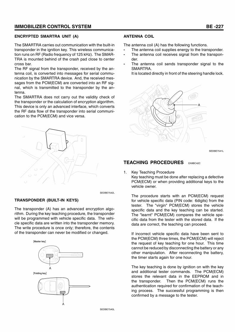
ENCRYPTED SMARTRA UNIT (A)
The SMARTRA carries out communication with the built-intransponder in the ignition key. This wireless communica-tion runs on RF (Radio frequency of 125 kHz). The SMAR-TRA is mounted behind of the crash pad close to centercross bar.The RF signal from the transponder, received by the an-tenna coil, is converted into messages for serial commu-nication by the SMARTRA device. And, the received mes-sages from the PCM(ECM) are converted into an RF sig-nal, which is transmitted to the transponder by the an-tenna.The SMARTRA does not carry out the validity check ofthe transponder or the calculation of encryption algorithm.This device is only an advanced interface, which convertsthe RF data flow of the transponder into serial communi-cation to the PCM(ECM) and vice versa.
SEDBE7542L
TRANSPONDER (BUILT-IN KEYS)
The transponder (A) has an advanced encryption algo-rithm. During the key teaching procedure, the transponderwill be programmed with vehicle specific data. The vehi-cle specific data are written into the transponder memory.The write procedure is once only; therefore, the contentsof the transponder can never be modified or changed.
A
[Master key]
[Folding key]
A
SEDBE7540L
ANTENNA COIL
The antenna coil (A) has the following functions.- The antenna coil supplies energy to the transponder.- The antenna coil receives signal from the transpon-
der.- The antenna coil sends transponder signal to the
SMARTRA.It is located directly in front of the steering handle lock.
A
SEDBE7541L
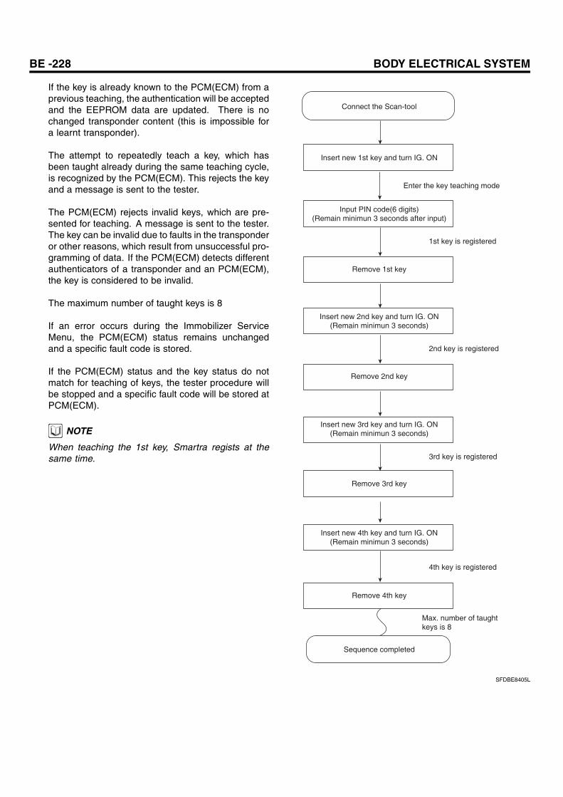
TEACHING PROCEDURES EA9BC42C
1. Key Teaching ProcedureKey teaching must be done after replacing a defectivePCM(ECM) or when providing additional keys to thevehicle owner.
The procedure starts with an PCM(ECM) requestfor vehicle specific data (PIN code: 6digits) from thetester. The "virgin" PCM(ECM) stores the vehiclespecific data and the key teaching can be started.The "learnt" PCM(ECM) compares the vehicle spe-cific data from the tester with the stored data. If thedata are correct, the teaching can proceed.
If incorrect vehicle specific data have been sent tothe PCM(ECM) three times, the PCM(ECM) will rejectthe request of key teaching for one hour. This timecannot be reduced by disconnecting the battery or anyother manipulation. After reconnecting the battery,the timer starts again for one hour.
The key teaching is done by ignition on with the keyand additional tester commands. The PCM(ECM)stores the relevant data in the EEPROM and inthe transponder. Then the PCM(ECM) runs theauthentication required for confirmation of the teach-ing process. The successful programming is thenconfirmed by a message to the tester.
BE -228 BODY ELECTRICAL SYSTEM
If the key is already known to the PCM(ECM) from aprevious teaching, the authentication will be acceptedand the EEPROM data are updated. There is nochanged transponder content (this is impossible fora learnt transponder).
The attempt to repeatedly teach a key, which hasbeen taught already during the same teaching cycle,is recognized by the PCM(ECM). This rejects the keyand a message is sent to the tester.
The PCM(ECM) rejects invalid keys, which are pre-sented for teaching. A message is sent to the tester.The key can be invalid due to faults in the transponderor other reasons, which result from unsuccessful pro-gramming of data. If the PCM(ECM) detects differentauthenticators of a transponder and an PCM(ECM),the key is considered to be invalid.
The maximum number of taught keys is 8
If an error occurs during the Immobilizer ServiceMenu, the PCM(ECM) status remains unchangedand a specific fault code is stored.
If the PCM(ECM) status and the key status do notmatch for teaching of keys, the tester procedure willbe stopped and a specific fault code will be stored atPCM(ECM).
NOTE
When teaching the 1st key, Smartra regists at thesame time.
Connect the Scan-tool
Insert new 1st key and turn IG. ON
Input PIN code(6 digits)(Remain minimun 3 seconds after input)
Insert new 3rd key and turn IG. ON(Remain minimun 3 seconds)
Remove 1st key
Remove 2nd key
Insert new 4th key and turn IG. ON(Remain minimun 3 seconds)
Remove 3rd key
Enter the key teaching mode
1st key is registered
2nd key is registered
3rd key is registered
4th key is registered
Max. number of taughtkeys is 8
Remove 4th key
Sequence completed
Insert new 2nd key and turn IG. ON(Remain minimun 3 seconds)
SFDBE8405L
IMMOBILIZER CONTROL SYSTEM BE -229
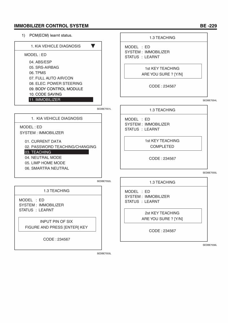
1) PCM(ECM) learnt status.
1. KIA VEHICLE DIAGNOSIS
MODEL : ED
04. ABS/ESP05. SRS-AIRBAG06. TPMS07. FULL AUTO AIR/CON08. ELEC. POWER STEERING09. BODY CONTROL MODULE10. CODE SAVING11. IMMOBILIZER
SEDBE7551L
1. KIA VEHICLE DIAGNOSIS
MODEL : ED
SYSTEM : IMMOBILIZER
01. CURRENT DATA02. PASSWORD TEACHING/CHANGING03. TEACHING04. NEUTRAL MODE05. LIMP HOME MODE06. SMARTRA NEUTRAL
SEDBE7552L
1.3 TEACHING
INPUT PIN OF SIX
FIGURE AND PRESS [ENTER] KEY
CODE : 234567
MODEL : EDSYSTEM : IMMOBILIZERSTATUS : LEARNT
SEDBE7553L
1.3 TEACHING
1st KEY TEACHING
ARE YOU SURE ? [Y/N]
CODE : 234567
MODEL : EDSYSTEM : IMMOBILIZERSTATUS : LEARNT
SEDBE7554L
1.3 TEACHING
1st KEY TEACHING
COMPLETED
CODE : 234567
MODEL : EDSYSTEM : IMMOBILIZERSTATUS : LEARNT
SEDBE7555L
1.3 TEACHING
2st KEY TEACHING
ARE YOU SURE ? [Y/N]
CODE : 234567
MODEL : EDSYSTEM : IMMOBILIZERSTATUS : LEARNT
SEDBE7556L
BE -230 BODY ELECTRICAL SYSTEM
1.3 TEACHING
2st KEY TEACHING
COMPLETED
CODE : 234567
MODEL : EDSYSTEM : IMMOBILIZERSTATUS : LEARNT
SEDBE7557L
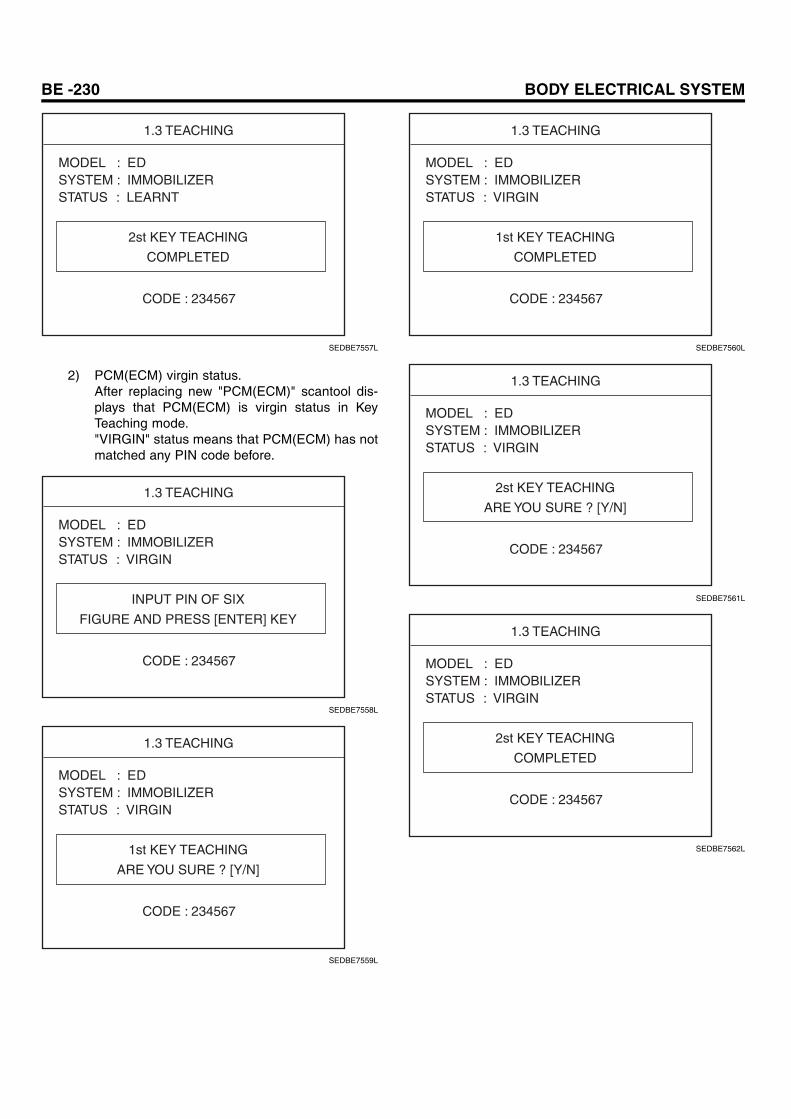
2) PCM(ECM) virgin status.After replacing new "PCM(ECM)" scantool dis-plays that PCM(ECM) is virgin status in KeyTeaching mode."VIRGIN" status means that PCM(ECM) has notmatched any PIN code before.
1.3 TEACHING
INPUT PIN OF SIX
FIGURE AND PRESS [ENTER] KEY
CODE : 234567
MODEL : EDSYSTEM : IMMOBILIZERSTATUS : VIRGIN
SEDBE7558L
1.3 TEACHING
1st KEY TEACHING
ARE YOU SURE ? [Y/N]
CODE : 234567
MODEL : EDSYSTEM : IMMOBILIZERSTATUS : VIRGIN
SEDBE7559L
1.3 TEACHING
1st KEY TEACHING
COMPLETED
CODE : 234567
MODEL : EDSYSTEM : IMMOBILIZERSTATUS : VIRGIN
SEDBE7560L
1.3 TEACHING
2st KEY TEACHING
ARE YOU SURE ? [Y/N]
CODE : 234567
MODEL : EDSYSTEM : IMMOBILIZERSTATUS : VIRGIN
SEDBE7561L
1.3 TEACHING
2st KEY TEACHING
COMPLETED
CODE : 234567
MODEL : EDSYSTEM : IMMOBILIZERSTATUS : VIRGIN
SEDBE7562L
IMMOBILIZER CONTROL SYSTEM BE -231
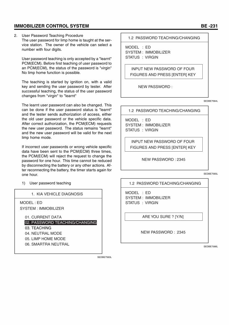
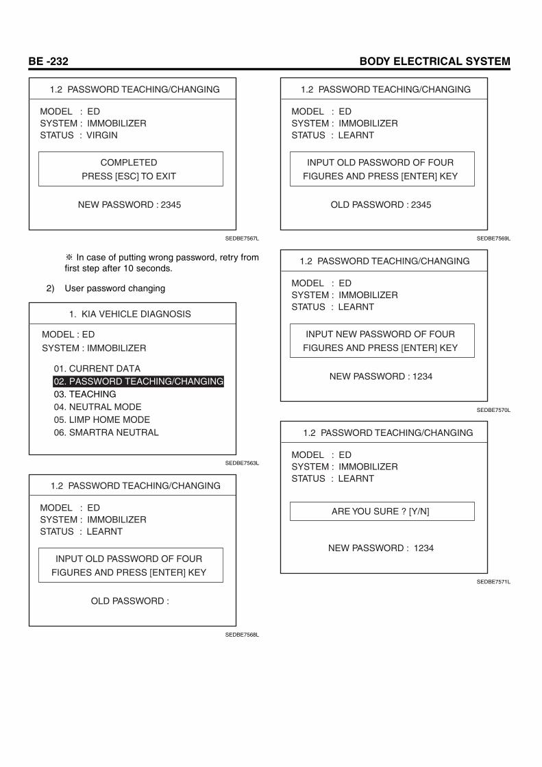
2. User Password Teaching ProcedureThe user password for limp home is taught at the ser-vice station. The owner of the vehicle can select anumber with four digits.
User password teaching is only accepted by a "learnt"PCM(ECM). Before first teaching of user password toan PCM(ECM), the status of the password is "virgin"No limp home function is possible.
The teaching is started by ignition on, with a validkey and sending the user password by tester. Aftersuccessful teaching, the status of the user passwordchanges from "virgin" to "learnt"
The learnt user password can also be changed. Thiscan be done if the user password status is "learnt"and the tester sends authorization of access, eitherthe old user password or the vehicle specific data.After correct authorization, the PCM(ECM) requeststhe new user password. The status remains "learnt"and the new user password will be valid for the nextlimp home mode.
If incorrect user passwords or wrong vehicle specificdata have been sent to the PCM(ECM) three times,the PCM(ECM) will reject the request to change thepassword for one hour. This time cannot be reducedby disconnecting the battery or any other actions. Af-ter reconnecting the battery, the timer starts again forone hour.
1) User password teaching
1. KIA VEHICLE DIAGNOSIS
MODEL : ED
SYSTEM : IMMOBILIZER
01. CURRENT DATA02. PASSWORD TEACHING/CHANGING03. TEACHING04. NEUTRAL MODE05. LIMP HOME MODE06. SMARTRA NEUTRAL
SEDBE7563L
1.2 PASSWORD TEACHING/CHANGING
INPUT NEW PASSWORD OF FOUR
FIGURES AND PRESS [ENTER] KEY
NEW PASSWORD :
MODEL : EDSYSTEM : IMMOBILIZERSTATUS : VIRGIN
SEDBE7564L
1.2 PASSWORD TEACHING/CHANGING
INPUT NEW PASSWORD OF FOUR
FIGURES AND PRESS [ENTER] KEY
NEW PASSWORD : 2345
MODEL : EDSYSTEM : IMMOBILIZERSTATUS : VIRGIN
SEDBE7565L
1.2 PASSWORD TEACHING/CHANGING
ARE YOU SURE ? [Y/N]
NEW PASSWORD : 2345
MODEL : EDSYSTEM : IMMOBILIZERSTATUS : VIRGIN
SEDBE7566L
BE -232 BODY ELECTRICAL SYSTEM
1.2 PASSWORD TEACHING/CHANGING
COMPLETED
PRESS [ESC] TO EXIT
NEW PASSWORD : 2345
MODEL : EDSYSTEM : IMMOBILIZERSTATUS : VIRGIN
SEDBE7567L
※ In case of putting wrong password, retry fromfirst step after 10 seconds.
2) User password changing
1. KIA VEHICLE DIAGNOSIS
MODEL : ED
SYSTEM : IMMOBILIZER
01. CURRENT DATA02. PASSWORD TEACHING/CHANGING03. TEACHING04. NEUTRAL MODE05. LIMP HOME MODE06. SMARTRA NEUTRAL
SEDBE7563L
1.2 PASSWORD TEACHING/CHANGING
INPUT OLD PASSWORD OF FOUR
FIGURES AND PRESS [ENTER] KEY
OLD PASSWORD :
MODEL : EDSYSTEM : IMMOBILIZERSTATUS : LEARNT
SEDBE7568L
1.2 PASSWORD TEACHING/CHANGING
INPUT OLD PASSWORD OF FOUR
FIGURES AND PRESS [ENTER] KEY
OLD PASSWORD : 2345
MODEL : EDSYSTEM : IMMOBILIZERSTATUS : LEARNT
SEDBE7569L
1.2 PASSWORD TEACHING/CHANGING
INPUT NEW PASSWORD OF FOUR
FIGURES AND PRESS [ENTER] KEY
NEW PASSWORD : 1234
MODEL : EDSYSTEM : IMMOBILIZERSTATUS : LEARNT
SEDBE7570L
1.2 PASSWORD TEACHING/CHANGING
ARE YOU SURE ? [Y/N]
NEW PASSWORD : 1234
MODEL : EDSYSTEM : IMMOBILIZERSTATUS : LEARNT
SEDBE7571L
IMMOBILIZER CONTROL SYSTEM BE -233
1.2 PASSWORD TEACHING/CHANGING
COMPLETED
PRESS [ESC] TO EXIT
NEW PASSWORD : 1234
MODEL : EDSYSTEM : IMMOBILIZERSTATUS : LEARNT
SEDBE7572L
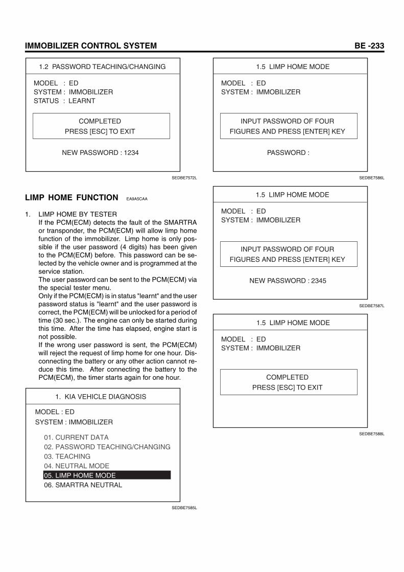
LIMP HOME FUNCTION EA9A5CAA
1. LIMP HOME BY TESTERIf the PCM(ECM) detects the fault of the SMARTRAor transponder, the PCM(ECM) will allow limp homefunction of the immobilizer. Limp home is only pos-sible if the user password (4 digits) has been givento the PCM(ECM) before. This password can be se-lected by the vehicle owner and is programmed at theservice station.The user password can be sent to the PCM(ECM) viathe special tester menu.Only if the PCM(ECM) is in status "learnt" and the userpassword status is "learnt" and the user password iscorrect, the PCM(ECM) will be unlocked for a period oftime (30 sec.). The engine can only be started duringthis time. After the time has elapsed, engine start isnot possible.If the wrong user password is sent, the PCM(ECM)will reject the request of limp home for one hour. Dis-connecting the battery or any other action cannot re-duce this time. After connecting the battery to thePCM(ECM), the timer starts again for one hour.
1. KIA VEHICLE DIAGNOSIS
MODEL : ED
SYSTEM : IMMOBILIZER
01. CURRENT DATA02. PASSWORD TEACHING/CHANGING03. TEACHING04. NEUTRAL MODE05. LIMP HOME MODE06. SMARTRA NEUTRAL
SEDBE7585L
1.5 LIMP HOME MODE
INPUT PASSWORD OF FOUR
FIGURES AND PRESS [ENTER] KEY
PASSWORD :
MODEL : EDSYSTEM : IMMOBILIZER
SEDBE7586L
1.5 LIMP HOME MODE
INPUT PASSWORD OF FOUR
FIGURES AND PRESS [ENTER] KEY
NEW PASSWORD : 2345
MODEL : EDSYSTEM : IMMOBILIZER
SEDBE7587L
1.5 LIMP HOME MODE
COMPLETED
PRESS [ESC] TO EXIT
MODEL : EDSYSTEM : IMMOBILIZER
SEDBE7588L
BE -234 BODY ELECTRICAL SYSTEM
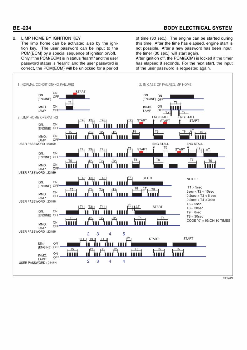
2. LIMP HOME BY IGNITION KEYThe limp home can be activated also by the igni-tion key. The user password can be input to thePCM(ECM) by a special sequence of ignition on/off.Only if the PCM(ECM) is in status "learnt" and the userpassword status is "learnt" and the user password iscorrect, the PCM(ECM) will be unlocked for a period
of time (30 sec.). The engine can be started duringthis time. After the time has elapsed, engine start isnot possible. After a new password has been input,the timer (30 sec.) will start again.After ignition off, the PCM(ECM) is locked if the timerhas elapsed 8 seconds. For the next start, the inputof the user password is requested again.
ONOFF
ONOFF
ONOFF
ONOFF
ONOFF
ONOFF
ONOFF
ONOFF
IGN.(ENGINE)
IMMO.LAMP
IGN.(ENGINE)
IMMO.LAMP
IGN.(ENGINE)
IMMO.LAMP
IGN.(ENGINE)
IMMO.LAMP
USER PASSWORD : 2345H
USER PASSWORD : 2345H
USER PASSWORD : 2345H
ONOFF
ONOFF
IGN.(ENGINE)
IMMO.LAMP
USER PASSWORD : 2345H2 3 4 5
START
ONOFF
ONOFF
IGN.(ENGINE)
IMMO.LAMP 2 3 4 4USER PASSWORD : 2345H
START
T1 T5
T5
T5
T5
T5
T5
T5
T3 T4
T3T4 T4 T2
T2 T2 T2
T3T4 T4
T2 T2 T2
T3T4 T4
T2 T2 T2
T3T4 T4
T2 T2 T2
T2
T2
T2 T
T
T
T
ENG STALL ENG STALL
ENG STALLENG STALL
T8
T9
T8 T8
T8 T8 T8
T8
T5 T5
T5 T5 T5T2 T2 T2
T3T4 T4 T2
T5
T5
ONOFF
ONOFF
IGN.(ENGINE)
IMMO.LAMP
T9START START
START
START START START
START
START
NOTE :
T1 > 5sec3sec < T2 < 10sec0.2sec < T3 < 5 sec0.2sec < T4 < 3secT5 = 5sec T6 < 30secT9 = 8secT8 = 30secCODE "0" = IG.ON 10 TIMES
LTIF740N
IMMOBILIZER CONTROL SYSTEM BE -235
REPLACEMENT EEB3E951
PROBLEMS AND REPLACEMENT PARTS:
Problem Part set Scan toolrequired?
All keys have beenlost
Blank key (4) YES
Antenna coil unitdoes not work
Antenna coil unit NO
ECM does not work PCM(ECM) YES
Ignition switch doesnot work
Ignition switch withAntenna coil unit
YES
Unidentified vehiclespecific data occurs
Key, PCM(ECM) YES
SMARTRA unit doesnot work
SMARTRA unit YES
REPLACEMENT OF ECM AND SMARTRA
In case of a defective ECM, the unit has to be replaced witha "virgin" or "neutral" ECM. All keys have to be taught tothe new ECM. Keys, which are not taught to the ECM, areinvalid for the new ECM (Refer to key teaching procedure).The vehicle specific data have to be left unchanged due tothe unique programming of transponder.In case of a defective SMARTRA, it needs teaching thesmartra. A new SMARTRA device replaces the old oneand smartra need teaching. There are no transponder-related data stored in this device.
1. Things to remember before a replacement(PCM(ECM))
When installing PCM(ECM) of car "A" on car "B"All non-virgin PCM(ECM)`s need to be neutralized before
installing on the other vehicles.
Neutralize the PCM(ECM) of car "A"
Installing the PCM(ECM) of car "A" on car "B"
Register the keys with the PIN code of car "B"
Register additional keys (Maximum of keys)All phases of key registration should be
completed in under 10 seconds
Registration completed
ETBF746A
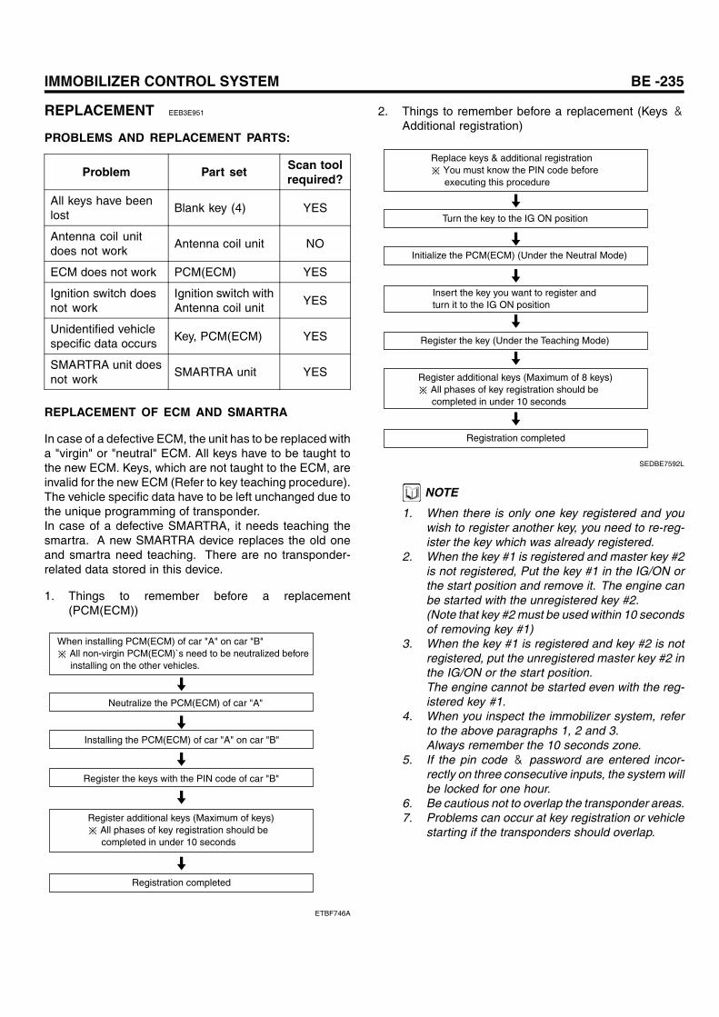
2. Things to remember before a replacement (Keys &Additional registration)
Replace keys & additional registration
Turn the key to the IG ON position
Initialize the PCM(ECM) (Under the Neutral Mode)
Insert the key you want to register and turn it to the IG ON position
Register additional keys (Maximum of 8 keys)All phases of key registration should be
completed in under 10 seconds
Registration completed
Register the key (Under the Teaching Mode)
SEDBE7592L
NOTE
1. When there is only one key registered and youwish to register another key, you need to re-reg-ister the key which was already registered.
2. When the key #1 is registered and master key #2is not registered, Put the key #1 in the IG/ON orthe start position and remove it. The engine canbe started with the unregistered key #2.(Note that key #2 must be used within 10 secondsof removing key #1)
3. When the key #1 is registered and key #2 is notregistered, put the unregistered master key #2 inthe IG/ON or the start position.The engine cannot be started even with the reg-istered key #1.
4. When you inspect the immobilizer system, referto the above paragraphs 1, 2 and 3.Always remember the 10 seconds zone.
5. If the pin code & password are entered incor-rectly on three consecutive inputs, the system willbe locked for one hour.
6. Be cautious not to overlap the transponder areas.7. Problems can occur at key registration or vehicle
starting if the transponders should overlap.
BE -236 BODY ELECTRICAL SYSTEM
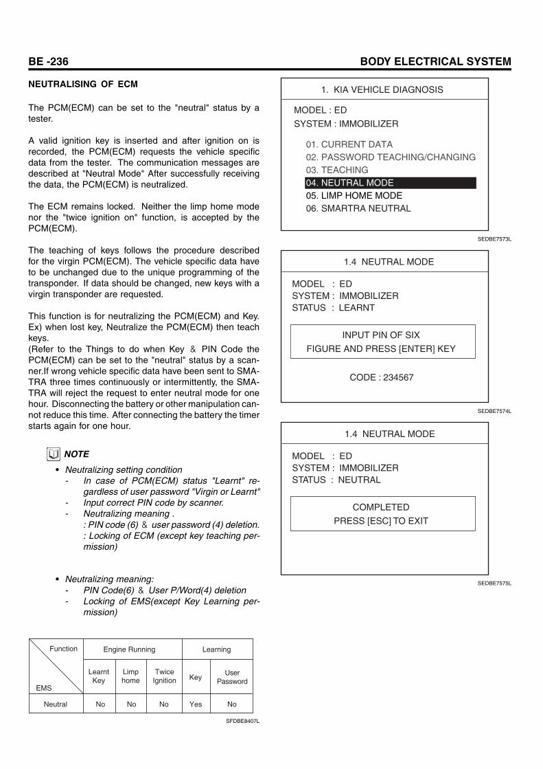
NEUTRALISING OF ECM
The PCM(ECM) can be set to the "neutral" status by atester.
A valid ignition key is inserted and after ignition on isrecorded, the PCM(ECM) requests the vehicle specificdata from the tester. The communication messages aredescribed at "Neutral Mode" After successfully receivingthe data, the PCM(ECM) is neutralized.
The ECM remains locked. Neither the limp home modenor the "twice ignition on" function, is accepted by thePCM(ECM).
The teaching of keys follows the procedure describedfor the virgin PCM(ECM). The vehicle specific data haveto be unchanged due to the unique programming of thetransponder. If data should be changed, new keys with avirgin transponder are requested.
This function is for neutralizing the PCM(ECM) and Key.Ex) when lost key, Neutralize the PCM(ECM) then teachkeys.(Refer to the Things to do when Key & PIN Code thePCM(ECM) can be set to the "neutral" status by a scan-ner.If wrong vehicle specific data have been sent to SMA-TRA three times continuously or intermittently, the SMA-TRA will reject the request to enter neutral mode for onehour. Disconnecting the battery or other manipulation can-not reduce this time. After connecting the battery the timerstarts again for one hour.
NOTE
• Neutralizing setting condition- In case of PCM(ECM) status "Learnt" re-
gardless of user password "Virgin or Learnt"- Input correct PIN code by scanner.- Neutralizing meaning .
: PIN code (6)& user password (4) deletion.: Locking of ECM (except key teaching per-mission)
• Neutralizing meaning:- PIN Code(6)& User P/Word(4) deletion- Locking of EMS(except Key Learning per-
mission)
Engine Running
LearntKey
Limphome
TwiceIgnition Key
UserPassword
Learning
Neutral No No No NoYes
Function
EMS
SFDBE8407L
1. KIA VEHICLE DIAGNOSIS
MODEL : ED
SYSTEM : IMMOBILIZER
01. CURRENT DATA02. PASSWORD TEACHING/CHANGING03. TEACHING04. NEUTRAL MODE05. LIMP HOME MODE06. SMARTRA NEUTRAL
SEDBE7573L
1.4 NEUTRAL MODE
INPUT PIN OF SIX
FIGURE AND PRESS [ENTER] KEY
CODE : 234567
MODEL : EDSYSTEM : IMMOBILIZERSTATUS : LEARNT
SEDBE7574L
1.4 NEUTRAL MODE
COMPLETED
PRESS [ESC] TO EXIT
MODEL : EDSYSTEM : IMMOBILIZERSTATUS : NEUTRAL
SEDBE7575L
IMMOBILIZER CONTROL SYSTEM BE -237
1. KIA VEHICLE DIAGNOSIS
MODEL : ED
SYSTEM : IMMOBILIZER
01. CURRENT DATA02. PASSWORD TEACHING/CHANGING03. TEACHING04. NEUTRAL MODE05. LIMP HOME MODE
SEDBE7576L
1.1 CURRENT DATA
FIX SCRN FULL PART GRPH HELP
01. NO. OF LEARNT KEY02. ECU STATUS03. KEY STATUS
0NEUTRALNOT CHECK
SEDBE7577L
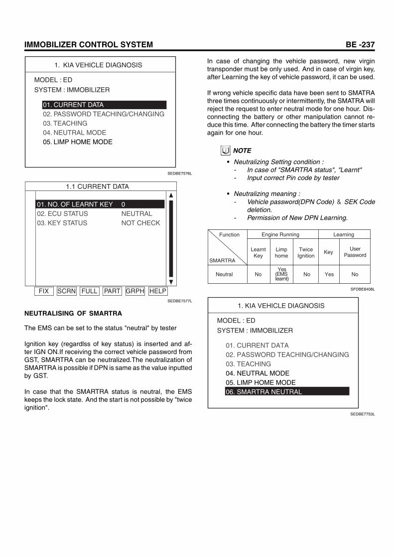
NEUTRALISING OF SMARTRA
The EMS can be set to the status "neutral" by tester
Ignition key (regardlss of key status) is inserted and af-ter IGN ON.If receiving the correct vehicle password fromGST, SMARTRA can be neutralized.The neutralization ofSMARTRA is possible if DPN is same as the value inputtedby GST.
In case that the SMARTRA status is neutral, the EMSkeeps the lock state. And the start is not possible by "twiceignition".
In case of changing the vehicle password, new virgintransponder must be only used. And in case of virgin key,after Learning the key of vehicle password, it can be used.
If wrong vehicle specific data have been sent to SMATRAthree times continuously or intermittently, the SMATRA willreject the request to enter neutral mode for one hour. Dis-connecting the battery or other manipulation cannot re-duce this time. After connecting the battery the timer startsagain for one hour.
NOTE
• Neutralizing Setting condition :- In case of "SMARTRA status", "Learnt"- Input correct Pin code by tester
• Neutralizing meaning :- Vehicle password(DPN Code)& SEK Code
deletion.- Permission of New DPN Learning.
Engine Running
LearntKey
Limphome
TwiceIgnition
KeyUser
Password
Learning
Neutral No No NoYesYes
(EMS Iearnt)
Function
SMARTRA
SFDBE8408L
1. KIA VEHICLE DIAGNOSIS
MODEL : ED
SYSTEM : IMMOBILIZER
01. CURRENT DATA02. PASSWORD TEACHING/CHANGING03. TEACHING04. NEUTRAL MODE05. LIMP HOME MODE06. SMARTRA NEUTRAL
SEDBE7753L
BE -238 BODY ELECTRICAL SYSTEM
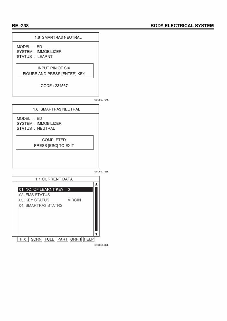
1.6 SMARTRA3 NEUTRAL
INPUT PIN OF SIX
FIGURE AND PRESS [ENTER] KEY
CODE : 234567
MODEL : EDSYSTEM : IMMOBILIZERSTATUS : LEARNT
SEDBE7754L
1.6 SMARTRA3 NEUTRAL
COMPLETED
PRESS [ESC] TO EXIT
MODEL : EDSYSTEM : IMMOBILIZERSTATUS : NEUTRAL
SEDBE7755L
1.1 CURRENT DATA
FIX SCRN FULL PART GRPH HELP
01. NO. OF LEARNT KEY02. EMS STATUS03. KEY STATUS04. SMARTRA3 STATRS
0
VIRGIN
SFDBE8412L
IMMOBILIZER CONTROL SYSTEM BE -239
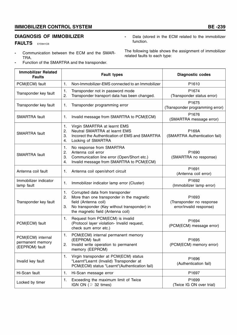
DIAGNOSIS OF IMMOBILIZERFAULTS E7D941CB
- Communication between the ECM and the SMAR-TRA.
- Function of the SMARTRA and the transponder.
- Data (stored in the ECM related to the immobilizerfunction.
The following table shows the assignment of immobilizerrelated faults to each type:
Immobilizer RelatedFaults
Fault types Diagnostic codes
PCM(ECM) fault 1. Non-Immobilizer-EMS connected to an Immobilizer P1610
Transponder key fault1. Transponder not in password mode2. Transponder transport data has been changed.
P1674(Transponder status error)
Transponder key fault 1. Transponder programming errorP1675
(Transponder programming error)
SMARTRA fault 1. Invalid message from SMARTRA to PCM(ECM)P1676
(SMARTRA message error)
SMARTRA fault
1. Virgin SMARTRA at learnt EMS2. Neutral SMARTRA at learnt EMS3. Incorect the Authentication of EMS and SMARTRA4. Locking of SMARTRA
P169A(SMARTRA Authentication fail)
SMARTRA fault
1. No response from SMARTRA2. Antenna coil error3. Communication line error (Open/Short etc.)4. Invalid message from SMARTRA to PCM(ECM)
P1690(SMARTRA no response)
Antenna coil fault 1. Antenna coil open/short circuitP1691
(Antenna coil error)
Immobilizer indicatorlamp fault
1. Immobilizer indicator lamp error (Cluster)P1692
(Immobilizer lamp error)
Transponder key fault
1. Corrupted data from transponder2. More than one transponder in the magnetic
field (Antenna coil)3. No transponder (Key without transponder) in
the magnetic field (Antenna coil)
P1693(Transponder no response
error/invalid response)
PCM(ECM) fault1. Request from PCM(ECM) is invalid
(Protocol layer violation- Invalid request,check sum error etc.)
P1694(PCM(ECM) message error)
PCM(ECM) internalpermanent memory(EEPROM) fault
1. PCM(ECM) internal permanent memory(EEPROM) fault
2. Invalid write operation to permanentmemory (EEPROM)
P1695(PCM(ECM) memory error)
Invalid key fault1. Virgin transponder at PCM(ECM) status
"Learnt"Learnt (Invalid) Transponder atPCM(ECM) status "Learnt"(Authentication fail)
P1696(Authentication fail)
Hi-Scan fault 1. Hi-Scan message error P1697
Locked by timer1. Exceeding the maximum limit of Twice
IGN ON (⊇ 32 times)P1699
(Twice IG ON over trial)