AProposalfora 2ndPREXRun -...
24
A Proposal for a 2 nd PREX Run Kent Paschke University of Virginia PAC 38 August 26, 2011
-
Upload
phunghuong -
Category
Documents
-
view
215 -
download
2
Transcript of AProposalfora 2ndPREXRun -...
A Proposal for a 2nd PREX Run
Kent Paschke University of Virginia
PAC 38August 26, 2011
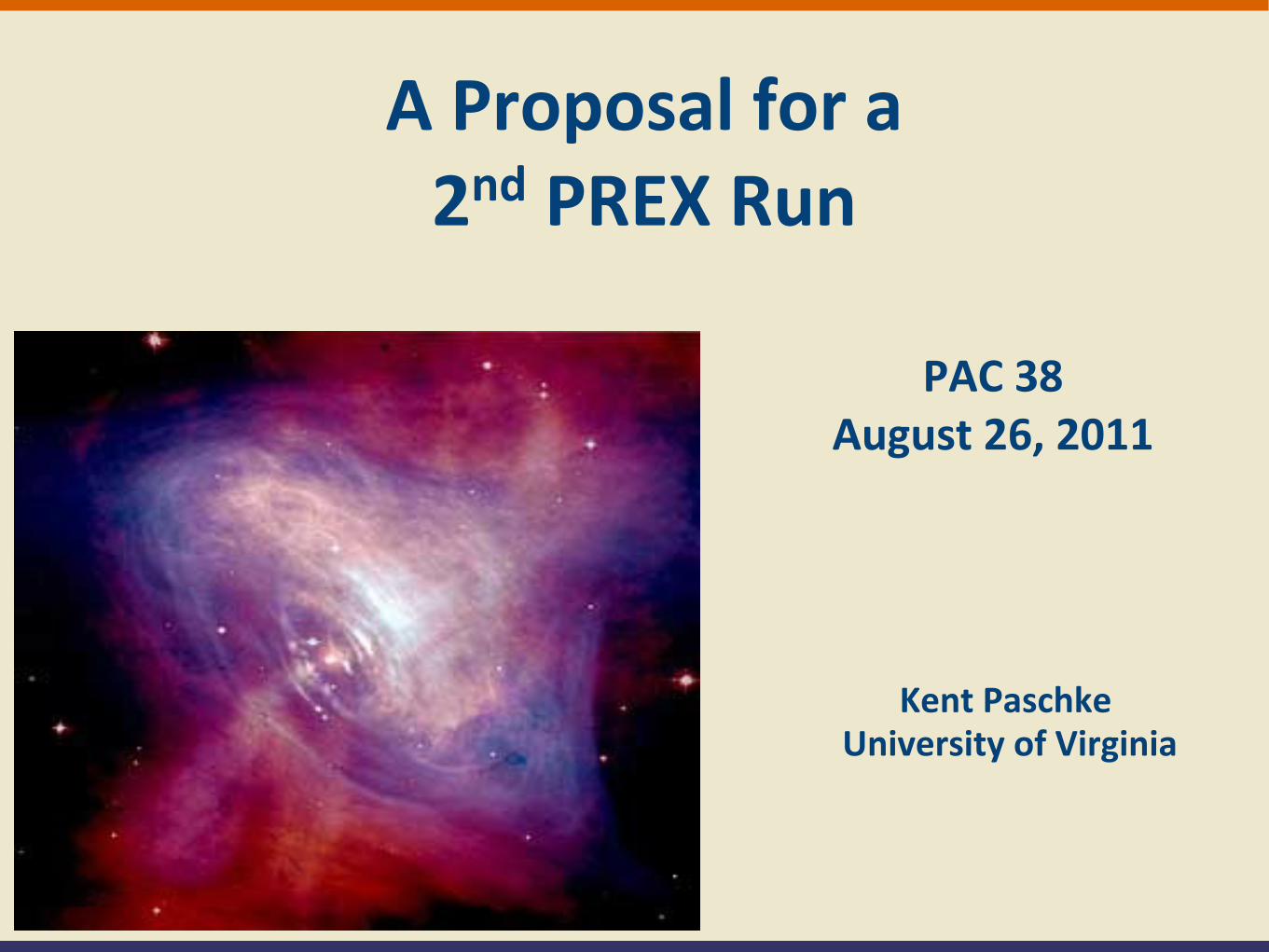
1− 4 sin2 θW � 1
A =GFQ2
2√2πα
�1− 4 sin2 θW − FN(Q2)
FP(Q2)
�
PAC 38 -‐ PREX-‐II ProposalKent Paschke
Weak Charge Distribution of Heavy NucleiNuclear theory predicts a neutron
“skin” on heavy nuclei
208Pb
Neutron distribuBon is not accessible to the charge-‐sensiBve photon.
γ
�
MEM = 4παQ2
Fp Q2( )
�
MPVNC = GF
21− 4sin2θW( )Fp Q2( ) − Fn Q2( )[ ]
Q2 ~ 0.01 GeV2 APV ~ 0.6 ppmRate ~1 GHz5o scattering angle
PREX (Pb-Radius EXperiment)
proton weak charge << neutron weak charge
for the spin-0 208Pb nucleus
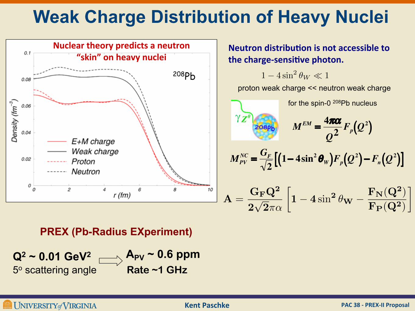
5.6 5.65 5.7 5.75 5.8
rn in
208Pb (fm)
0.25
0.26
0.27
0.28
0.29
0.3
Fn(Q
2)/
N
Skyrme
covariant mesoncovariant point coupling
PAC 38 -‐ PREX-‐II ProposalKent Paschke
A crucial calibration point for nuclear theory
( R.J. Furnstahl )
…and measuring RN pins down the symmetry energy
24 26 28 30 32 34 36 38 40 42 44
symmetry energy a4 (MeV)
0.05
0.1
0.15
0.2
0.25
0.3
0.35
r n!
rp (
fm)
24 26 28 30 32 34 36 38 40 42 44
symmetry energy a4 (MeV)
0.05
0.1
0.15
0.2
0.25
0.3
0.35
r n!
rp (
fm)
Skyrme
relativistic mesonrelativistic point coupling
24 26 28 30 32 34 36 38 40 42 44
symmetry energy a4 (MeV)
0.05
0.1
0.15
0.2
0.25
0.3
0.35
r n!
rp (
fm)
The single measurement of Fn translates to a measurement of Rn via mean-field nuclear models
Rn calibrates the EOS of neutron rich matter - provides an important calibration point for nuclear theory and description of neutron stars
PAC 38 -‐ PREX-‐II ProposalKent Paschke
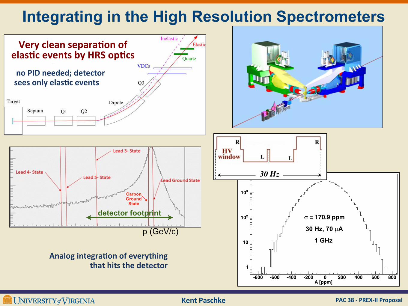
Integrating in the High Resolution Spectrometers
PREx Collaboration Jefferson Lab Hall A!
"
#
$
Experimental Setup• Std. Hall A HRS Spects. with detector huts well shielded against bkgds.• Running dual, symmetric arms cancels out Atrans and other systematics• Use septum magnet to bend 5o to 12.5o
• Upgraded polarimetry (non-inv. Compton! 1%, Inv. Moller! 1%)• 0.5mm thick Lead in between two 0.15mm Diamond targets (! 1"1in2)with cryogenically cooled frame; used fast rastered beam• Quartz Cerenkov detectors with 18-bit integrating ADCs
Dustin McNulty, PANIC11, Massachusetts Institute of Technology, Cambridge, MA, July 24 - 29, 2011 11
Very clean separaBon ofelasBc events by HRS opBcs
no PID needed; detector sees only elas1c events
p (GeV/c)
Carbon Ground
State
detector footprint
Analog integra1on of everything that hits the detector
A [ppm]-800 -600 -400 -200 0 200 400 600 800
1
10
210
310
A, Pb/D #1, Run 4714µDither Corrected Asymmetry, I = 70
= 170.9 ppm!
FIGURE 1. Distribution of the asymmetries for a typical run at 70µA. Beam-relatednoise has been subtracted using the standard “dither correction” method. The width of171 ppm is consistent with counting statistics.
24
30 Hz
30 Hz, 70 µA
1 GHz
PAC 38 -‐ PREX-‐II ProposalKent Paschke
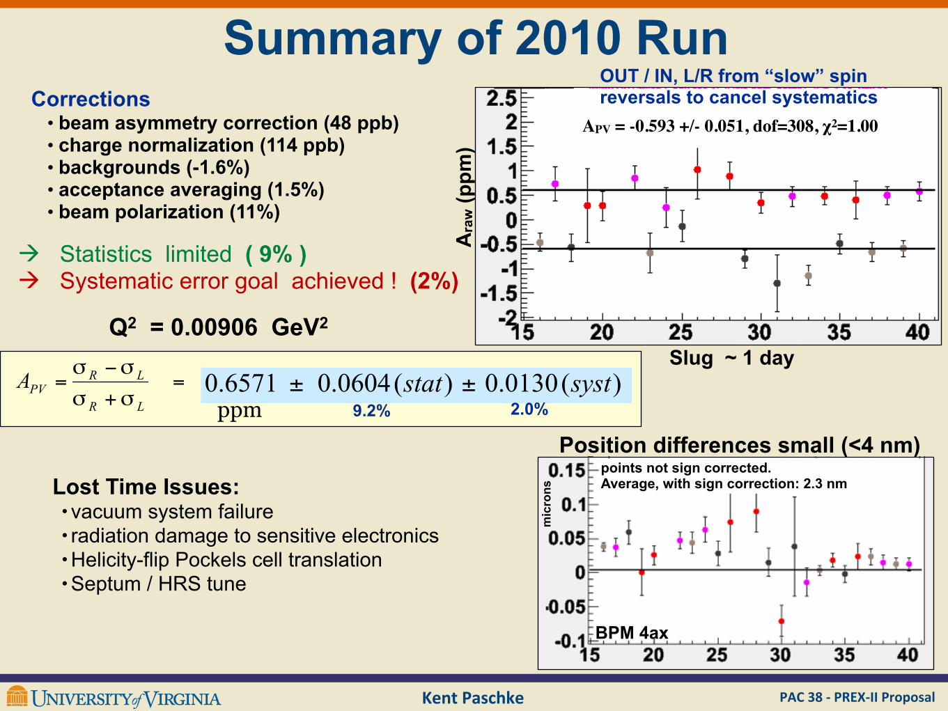
Summary of 2010 Run
Ara
w (p
pm)
Slug ~ 1 day
APV = -0.593 +/- 0.051, dof=308, χ2=1.00
OUT / IN, L/R from “slow” spin reversals to cancel systematicsCorrections
• beam asymmetry correction (48 ppb) • charge normalization (114 ppb) • backgrounds (-1.6%)• acceptance averaging (1.5%)• beam polarization (11%)
Q2 = 0.00906 GeV2
ppm 9.2% 2.0%
à Statistics limited ( 9% )à Systematic error goal achieved ! (2%)
Lost Time Issues:• vacuum system failure• radiation damage to sensitive electronics•Helicity-flip Pockels cell translation•Septum / HRS tune
BPM 4ax
mic
rons
points not sign corrected. Average, with sign correction: 2.3 nm
Position differences small (<4 nm)
Kent Paschke PAC 38 -‐ PREX-‐II Proposal
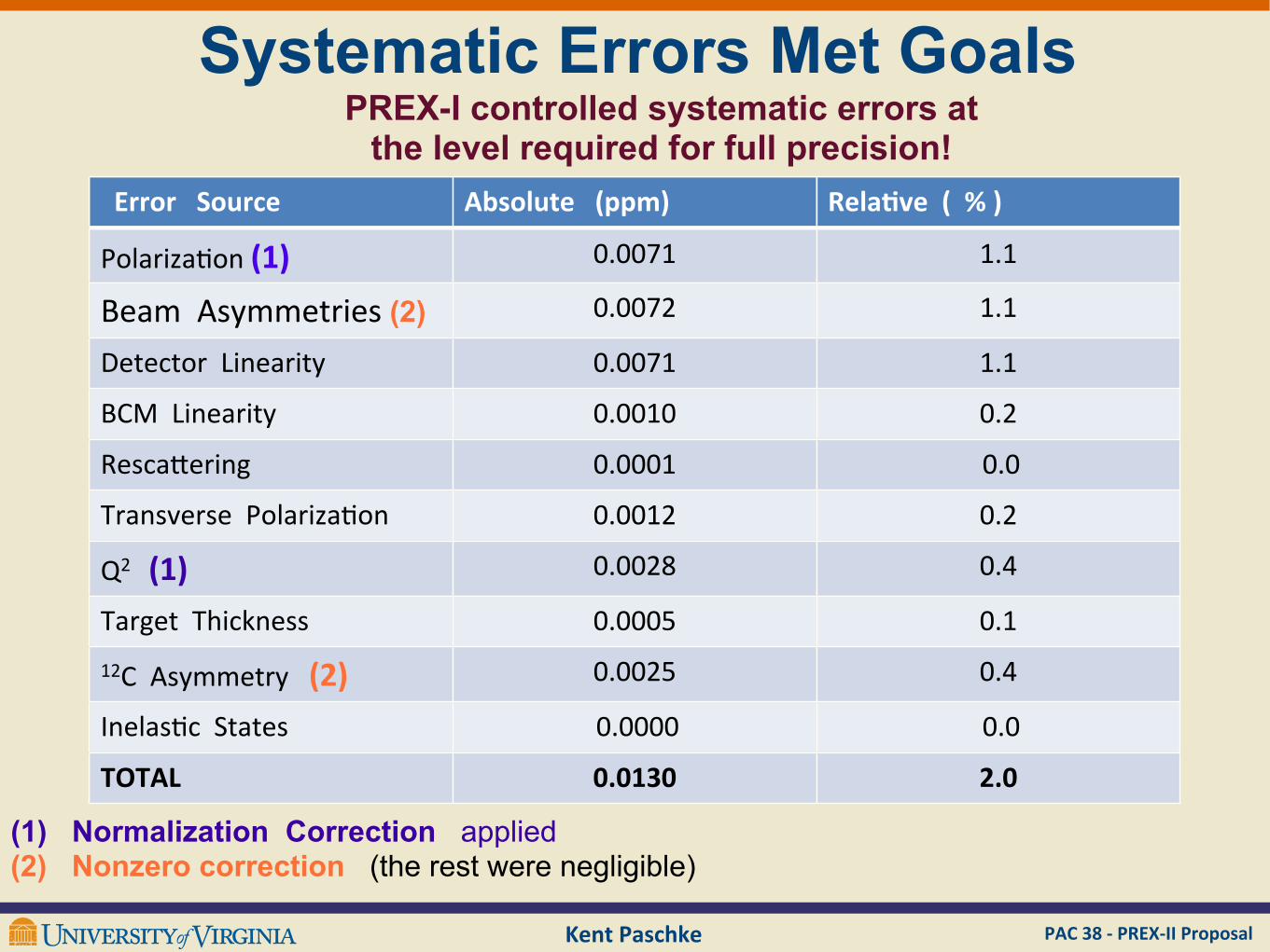
Error Source Absolute (ppm) RelaBve ( % )
Polariza(on (1) 0.0071 1.1
Beam Asymmetries (2) 0.0072 1.1
Detector Linearity 0.0071 1.1
BCM Linearity 0.0010 0.2
Resca;ering 0.0001 0.0
Transverse Polariza(on 0.0012 0.2
Q2 (1) 0.0028 0.4
Target Thickness 0.0005 0.112C Asymmetry (2) 0.0025 0.4
Inelas(c States 0.0000 0.0
TOTAL 0.0130 2.0
(1) Normalization Correction applied(2) Nonzero correction (the rest were negligible)
Systematic Errors Met GoalsPREX-I controlled systematic errors at
the level required for full precision!
Kent Paschke PAC 38 -‐ PREX-‐II Proposal
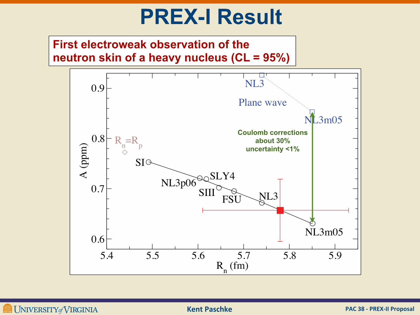
PREX-I ResultFirst electroweak observation of the neutron skin of a heavy nucleus (CL = 95%)
!"# !"! !"$ !"% !"& !"'()*+,-.
/"$
/"%
/"&
/"'0*+11-.
23
4561/$ 257#
829 456
456-/!
2333
456-/!:;<)=*><?=
456
()@(1Coulomb corrections
about 30%uncertainty <1%
!"# !"! !"$ !"% !"& !"'()*+,-.
/"$
/"%
/"&
/"'
0*+11-.
23
4561/$ 257#
829 456
456-/!
2333
456-/!:;<)=*><?=
456
()@(1
HebelerSteinerTamiiTsang
PREX-IIproposal
Kent Paschke PAC 38 -‐ PREX-‐II Proposal
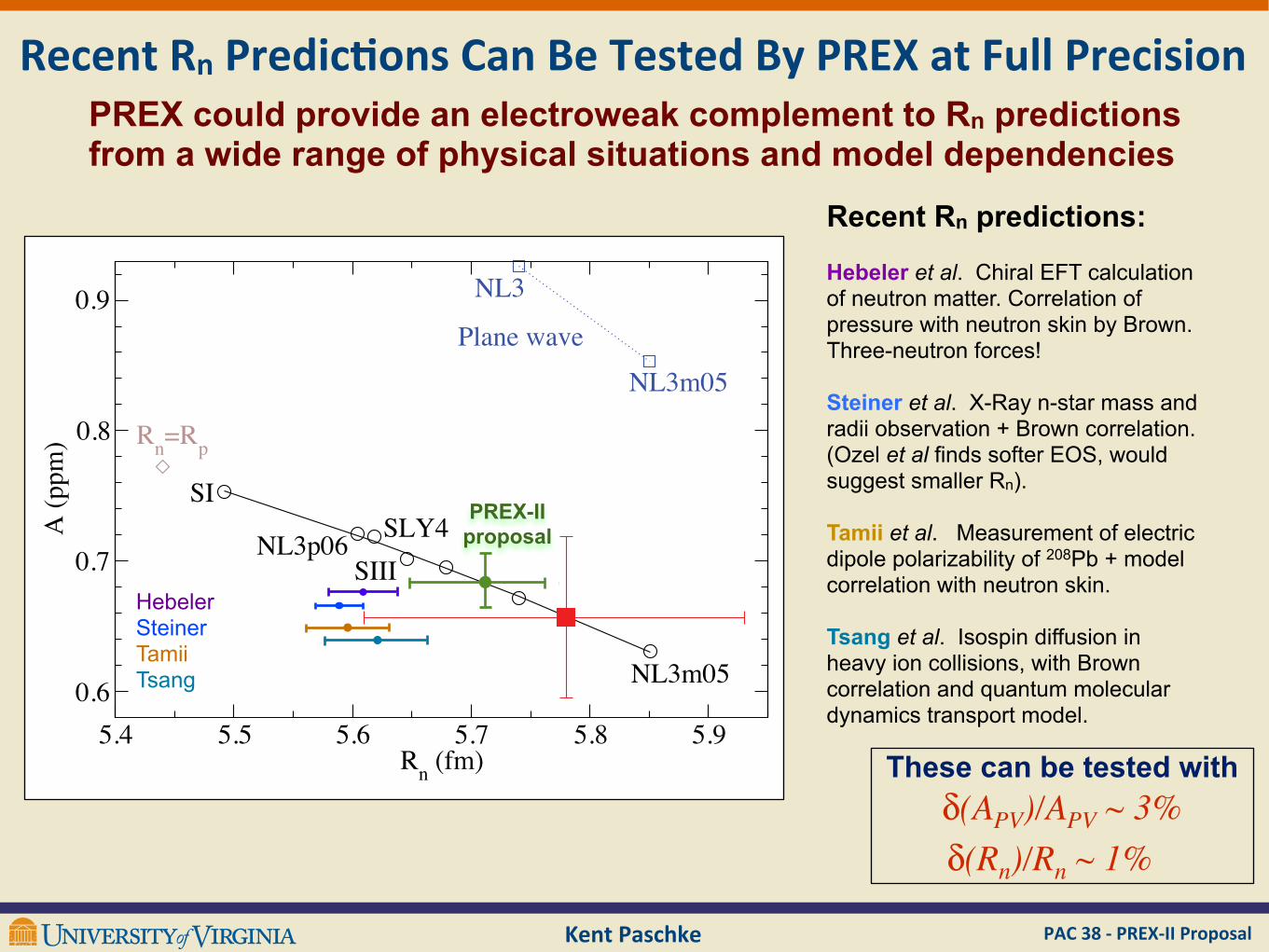
PREX could provide an electroweak complement to Rn predictions from a wide range of physical situations and model dependencies
Recent Rn predictions:
Hebeler et al. Chiral EFT calculation of neutron matter. Correlation of pressure with neutron skin by Brown. Three-neutron forces!
Steiner et al. X-Ray n-star mass and radii observation + Brown correlation. (Ozel et al finds softer EOS, would suggest smaller Rn).
Tamii et al. Measurement of electric dipole polarizability of 208Pb + model correlation with neutron skin.
Tsang et al. Isospin diffusion in heavy ion collisions, with Brown correlation and quantum molecular dynamics transport model.
Recent Rn Predic7ons Can Be Tested By PREX at Full Precision
δ(APV)/APV ~ 3%δ(Rn)/Rn ~ 1%
These can be tested with
PAC 38 -‐ PREX-‐II ProposalKent Paschke
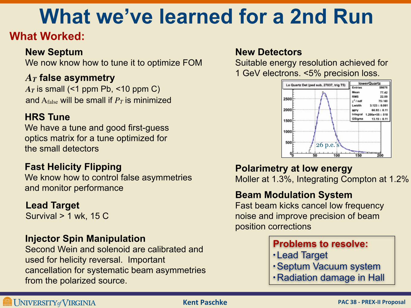
What we’ve learned for a 2nd RunWhat Worked:
Problems to resolve: • Lead Target • Septum Vacuum system• Radiation damage in Hall
26 p.e.’s
New SeptumWe now know how to tune it to optimize FOM
AT false asymmetryAT is small (<1 ppm Pb, <10 ppm C) and Afalse will be small if PT is minimized
HRS TuneWe have a tune and good first-guess optics matrix for a tune optimized for the small detectors
Fast Helicity FlippingWe know how to control false asymmetries and monitor performance
Beam Modulation SystemFast beam kicks cancel low frequency noise and improve precision of beam position corrections
Injector Spin ManipulationSecond Wein and solenoid are calibrated and used for helicity reversal. Important cancellation for systematic beam asymmetries from the polarized source.
Lead TargetSurvival > 1 wk, 15 C
New DetectorsSuitable energy resolution achieved for 1 GeV electrons. <5% precision loss.
Polarimetry at low energyMoller at 1.3%, Integrating Compton at 1.2%
Kent Paschke PAC 38 -‐ PREX-‐II Proposal
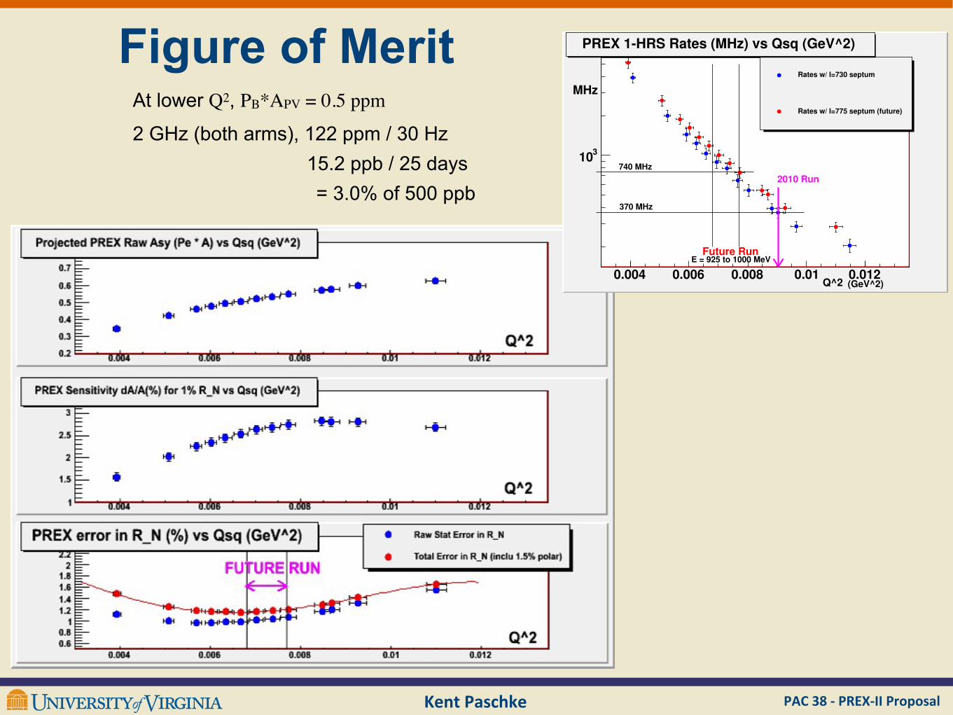
Figure of Merit
0.004 0.006 0.008 0.01 0.012
310
Rates w/ I=730 septum
Rates w/ I=775 septum (future)
PREX 1-HRS Rates (MHz) vs Qsq (GeV^2)
Future RunE = 925 to 1000 MeV
2010 Run
370 MHz
740 MHz
Q^2 (GeV^2)
MHz
FIGURE 13. Simulated rates in one HRS versus Q2for two assumptions about septum
current setting. For I=729 Amps (2010 run) the minimum scattering angle was 4.58 degrees
and was not optimal. For I=775 Amps (suggested future run point) the min angle will be
4.35 degrees. By putting the septum there and reducing the energy to the range 925 to
1000 MeV, we expect to double the rate.
36
2 GHz (both arms), 122 ppm / 30 Hz
At lower Q2, PB*APV = 0.5 ppm
15.2 ppb / 25 days= 3.0% of 500 ppb
PAC 38 -‐ PREX-‐II ProposalKent Paschke
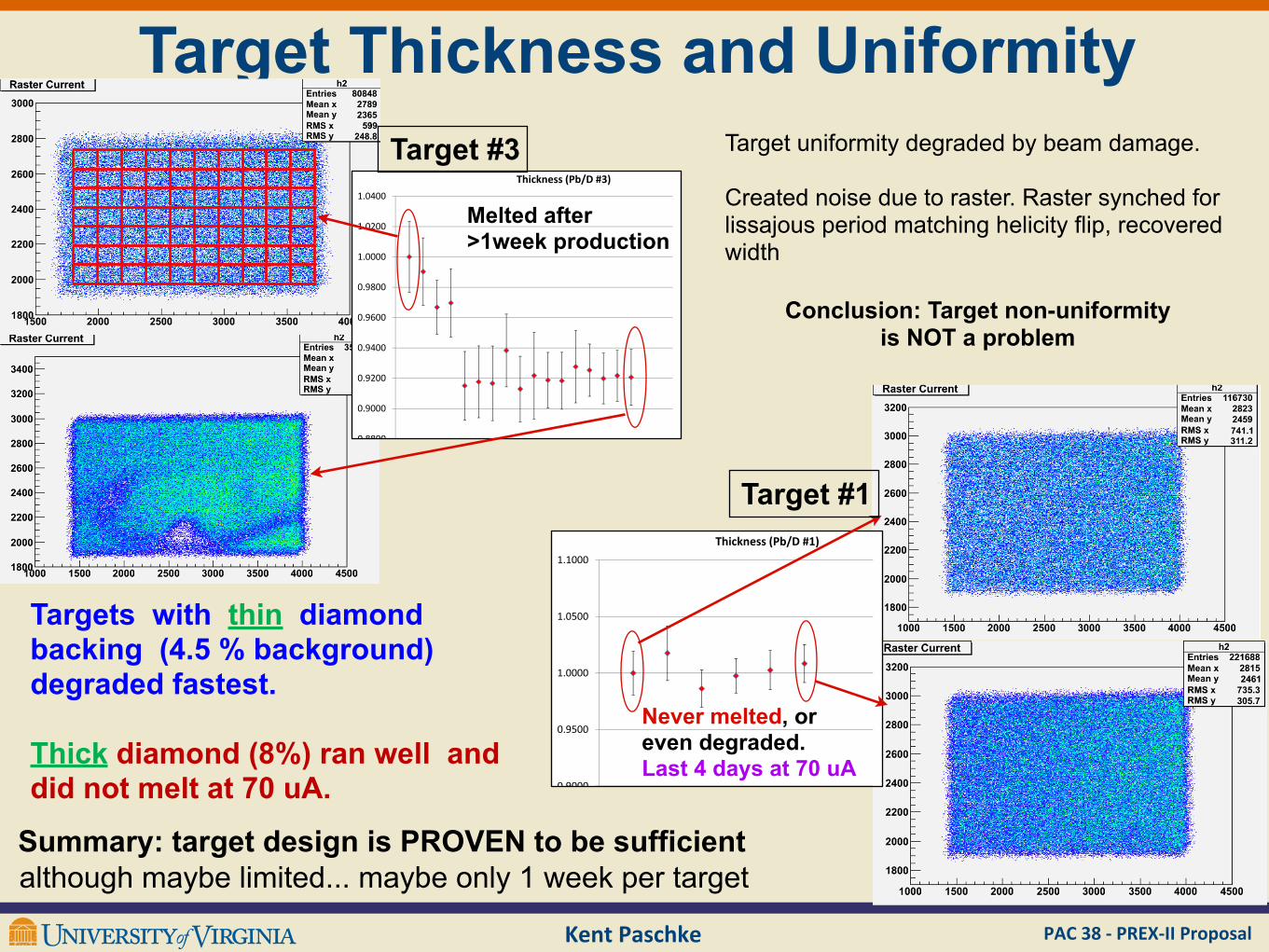
Target Thickness and Uniformity
!"
!"#$%&&'(
)*+,-./0 12+-32#,/0
#$%&'!"
!"
!"#$%&%'(
)*+,-./0 12+-32#,/0
#$%&'!"
!"
#$%%##
#$&###
#$&"##
#$&'##
#$&(##
#$&%##
!$####
!$#"##
!$#'##
# ) !# !) "#
!"#$%&'(()*+,-.)/01
*+,-./011234567289:
4;<02!"Target #3
Melted after >1week production
!
!"#$%&'&(
)*+,-./0 12+-32#,/0
"#$%&!
!
!"#$%&'((
)*+,-./0 12+-32#,/0
"#$%&!
!
"#$"""
"#$%""
&#""""
&#"%""
&#&"""
" ' ! ( )
!"#$%&'(()*+,-.)/01
*+,-./01123456728&9
4:;02!Target #1
Never melted, or even degraded. Last 4 days at 70 uA
Target uniformity degraded by beam damage.
Created noise due to raster. Raster synched for lissajous period matching helicity flip, recovered width
Conclusion: Target non-uniformity is NOT a problem
Targets with thin diamond backing (4.5 % background) degraded fastest.
Thick diamond (8%) ran well and did not melt at 70 uA.
Summary: target design is PROVEN to be sufficientalthough maybe limited... maybe only 1 week per target
Kent Paschke PAC 38 -‐ PREX-‐II Proposal
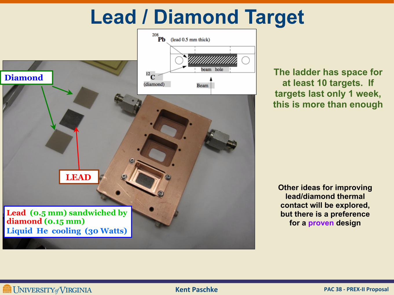
Lead / Diamond Target
Diamond
LEAD
Lead (0.5 mm) sandwiched by diamond (0.15 mm)Liquid He cooling (30 Watts)
Other ideas for improving lead/diamond thermal
contact will be explored, but there is a preference
for a proven design
The ladder has space for at least 10 targets. If
targets last only 1 week, this is more than enough

PAC 38 -‐ PREX-‐II ProposalKent Paschke
scattering chamber
HRS-L
HRS-Rcollimator
Septum Magnet collimator
Tungsten beamline collimator
sieve box
5o Septum to augment the HRS
to electric form factor of the proton. The averageinclusive analyzing power for carbon, with angularacceptance from 5! to 20! (solid squares) and 5! to70! (solid circles), is shown in Fig. 17.
4. Beamline
The instrumentation along the beamline (shownin Fig. 18) consists of various elements necessary
to transport the electron beam onto the target andinto the dump, and to measure simultaneously therelevant properties of the beam. The resolutionand accuracy requirements are such that specialattention is paid to the control and determinationof the beam energy, current and polarization, andalso to the position, direction, size and stability ofthe beam at the Hall A target location.
Table 2 lists all the beam parameters monitoredalong the beamline and the associated instrumen-tation. In nearly all cases, two or more indepen-dent methods are available to determine andmonitor the various parameters in order toprovide confidence in the absolute measurementsand redundancy if any of the instrumentationshould fail during a run. The beam parameterslisted in Table 2 are determined and monitored ata level which in most cases meets or exceeds theneeds of the approved experiments. The variouselements along the beamline are listed anddescribed in detail in the Hall A OperationsManual [33].
4.1. Basic beamline
The beam entrance channel consists of 63:5 mminner diameter stainless steel tubing connectedwith conflat flanges. Through magnets the innerdiameter of the tubing is restricted to 25:4 mm:
ARTICLE IN PRESS
Proton Momentum [GeV/c]
0.5 1 1.5 2 2.5 3A
naly
zin
g P
ow
er
0
0.1
0.2
0.3
0.4
0.5
0.6
20°!c"!5°
70°!c"!5°
p-Carbon Inclusive Analyzing Powers
Fig. 17. The average analyzing power of the carbon analyzer asa function of proton momentum. Solid squares are averagesover scattering angles from 5! to 20! and the solid circles forthose from 5! to 70!:
EP
RASTER
BCM
COMPTONPOLARIMETER
MOLLERPOLARIMETER
BPM
Q1
Q2
DIPOLE
Q3
SHIELD HOUSE
BEAMDUMP
ACCESSRAMP
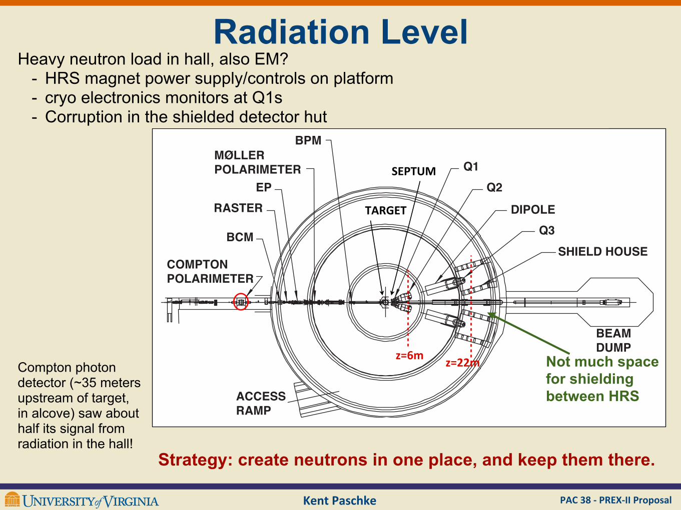
Fig. 18. Schematic layout of Hall A, indicating the location of the Compton and the M^ller polarimeters, the raster, the EP energymeasurement system, the beam current monitors (BCM) and the beam position monitors (BPM) upstream of the target. Also indicatedare the locations of the components of one of the high-resolution spectrometers (Q1, Q2, dipole, Q3 and shield house) and of the beamdump and the truck access ramp.
J. Alcorn et al. / Nuclear Instruments and Methods in Physics Research A 522 (2004) 294–346316
SEPTUM
TARGET
PAC 38 -‐ PREX-‐II ProposalKent Paschke
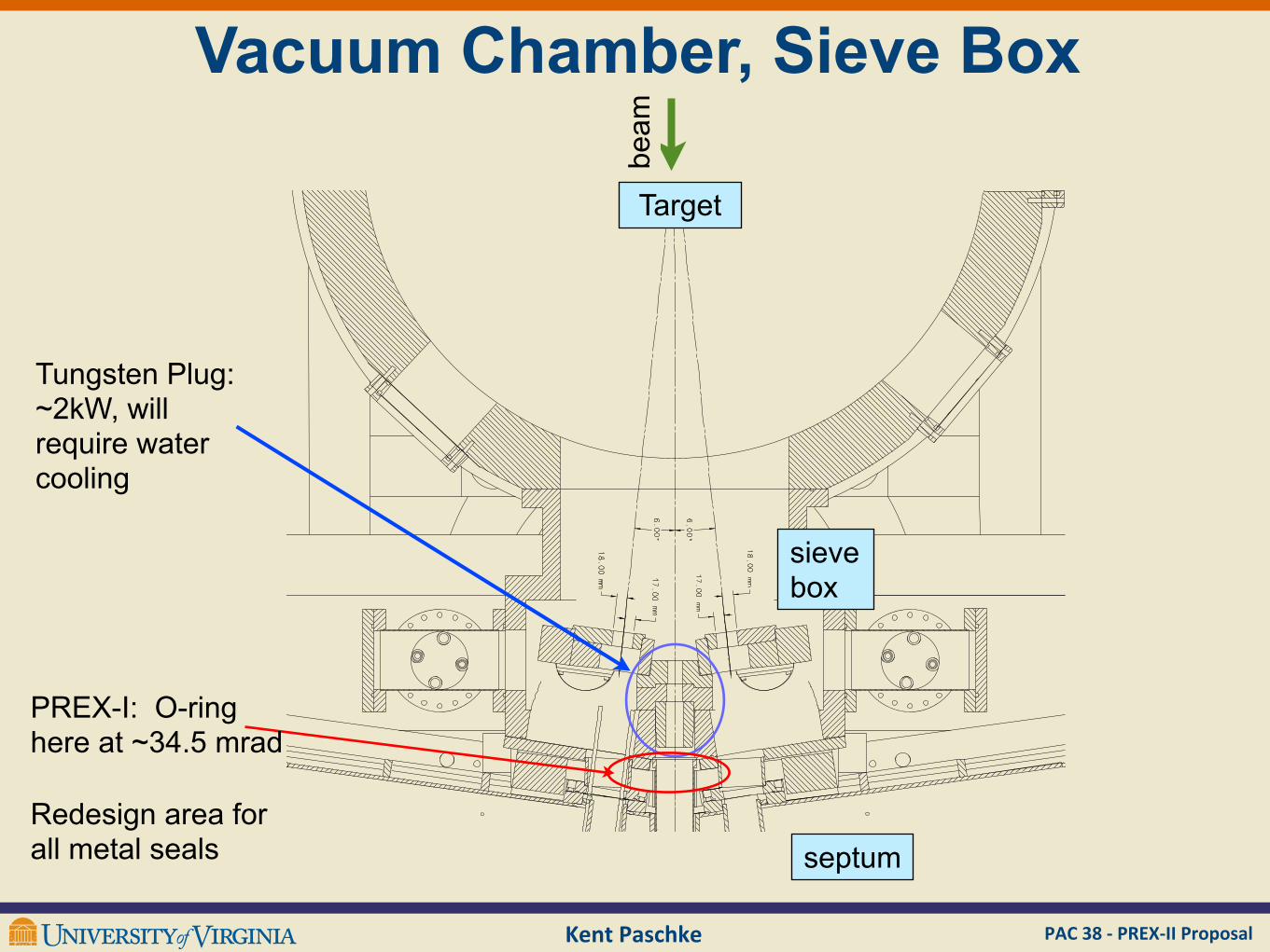
Vacuum Chamber, Sieve Box
Tungsten Plug:~2kW, will require water cooling
sieve box
septum
Target
beam
PREX-I: O-ring here at ~34.5 mrad
Redesign area for all metal seals
PAC 38 -‐ PREX-‐II ProposalKent Paschke
Radiation Level
to electric form factor of the proton. The averageinclusive analyzing power for carbon, with angularacceptance from 5! to 20! (solid squares) and 5! to70! (solid circles), is shown in Fig. 17.
4. Beamline
The instrumentation along the beamline (shownin Fig. 18) consists of various elements necessary
to transport the electron beam onto the target andinto the dump, and to measure simultaneously therelevant properties of the beam. The resolutionand accuracy requirements are such that specialattention is paid to the control and determinationof the beam energy, current and polarization, andalso to the position, direction, size and stability ofthe beam at the Hall A target location.
Table 2 lists all the beam parameters monitoredalong the beamline and the associated instrumen-tation. In nearly all cases, two or more indepen-dent methods are available to determine andmonitor the various parameters in order toprovide confidence in the absolute measurementsand redundancy if any of the instrumentationshould fail during a run. The beam parameterslisted in Table 2 are determined and monitored ata level which in most cases meets or exceeds theneeds of the approved experiments. The variouselements along the beamline are listed anddescribed in detail in the Hall A OperationsManual [33].
4.1. Basic beamline
The beam entrance channel consists of 63:5 mminner diameter stainless steel tubing connectedwith conflat flanges. Through magnets the innerdiameter of the tubing is restricted to 25:4 mm:
ARTICLE IN PRESS
Proton Momentum [GeV/c]
0.5 1 1.5 2 2.5 3A
na
lyzin
g P
ow
er
0
0.1
0.2
0.3
0.4
0.5
0.6
20°!c"!5°
70°!c"!5°
p-Carbon Inclusive Analyzing Powers
Fig. 17. The average analyzing power of the carbon analyzer asa function of proton momentum. Solid squares are averagesover scattering angles from 5! to 20! and the solid circles forthose from 5! to 70!:
EP
RASTER
BCM
COMPTONPOLARIMETER
MOLLERPOLARIMETER
BPM
Q1
Q2
DIPOLE
Q3
SHIELD HOUSE
BEAMDUMP
ACCESSRAMP
Fig. 18. Schematic layout of Hall A, indicating the location of the Compton and the M^ller polarimeters, the raster, the EP energymeasurement system, the beam current monitors (BCM) and the beam position monitors (BPM) upstream of the target. Also indicatedare the locations of the components of one of the high-resolution spectrometers (Q1, Q2, dipole, Q3 and shield house) and of the beamdump and the truck access ramp.
J. Alcorn et al. / Nuclear Instruments and Methods in Physics Research A 522 (2004) 294–346316
Compton photon detector (~35 meters upstream of target, in alcove) saw about half its signal from radiation in the hall!
Heavy neutron load in hall, also EM?- HRS magnet power supply/controls on platform- cryo electronics monitors at Q1s - Corruption in the shielded detector hut
Strategy: create neutrons in one place, and keep them there.
Not much space for shielding between HRS
SEPTUM
TARGET
z=6m z=22m
PAC 38 -‐ PREX-‐II ProposalKent Paschke
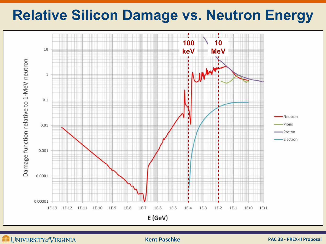
Relative Silicon Damage vs. Neutron Energy
100 keV
10 MeV
PAC 38 -‐ PREX-‐II ProposalKent Paschke
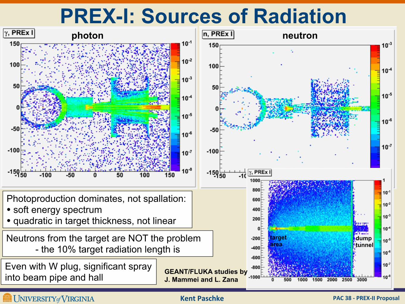
PREX-I: Sources of Radiation
Even with W plug, significant spray into beam pipe and hall
photon neutron
dumptunnel
targetarea
Photoproduction dominates, not spallation: • soft energy spectrum• quadratic in target thickness, not linear
Neutrons from the target are NOT the problem - the 10% target radiation length is
GEANT/FLUKA studies by J. Mammei and L. Zana
PAC 38 -‐ PREX-‐II ProposalKent Paschke
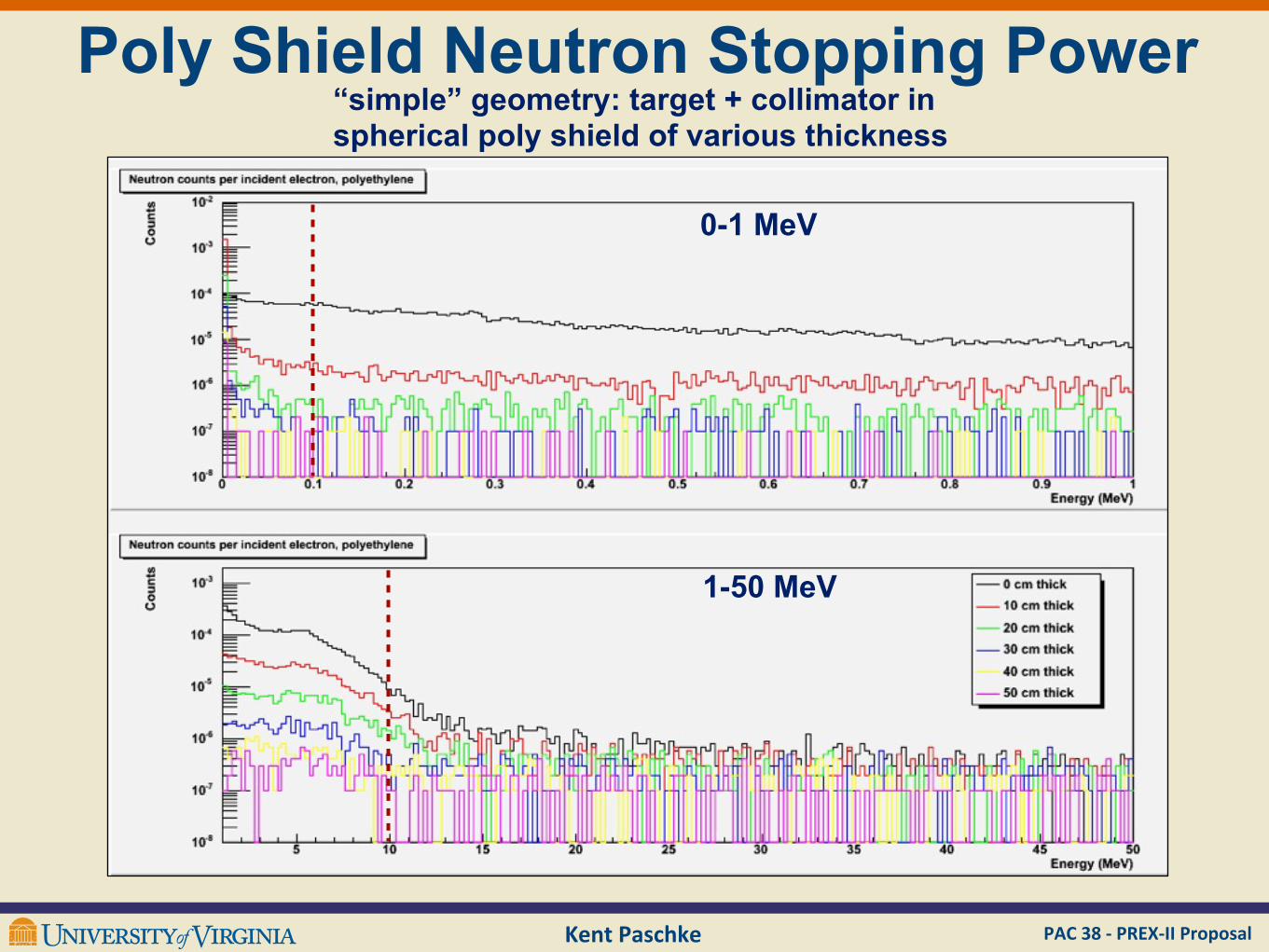
Poly Shield Neutron Stopping Power“simple” geometry: target + collimator in spherical poly shield of various thickness
0-1 MeV
1-50 MeV
PAC 38 -‐ PREX-‐II ProposalKent Paschke
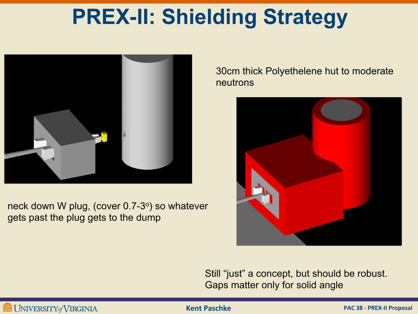
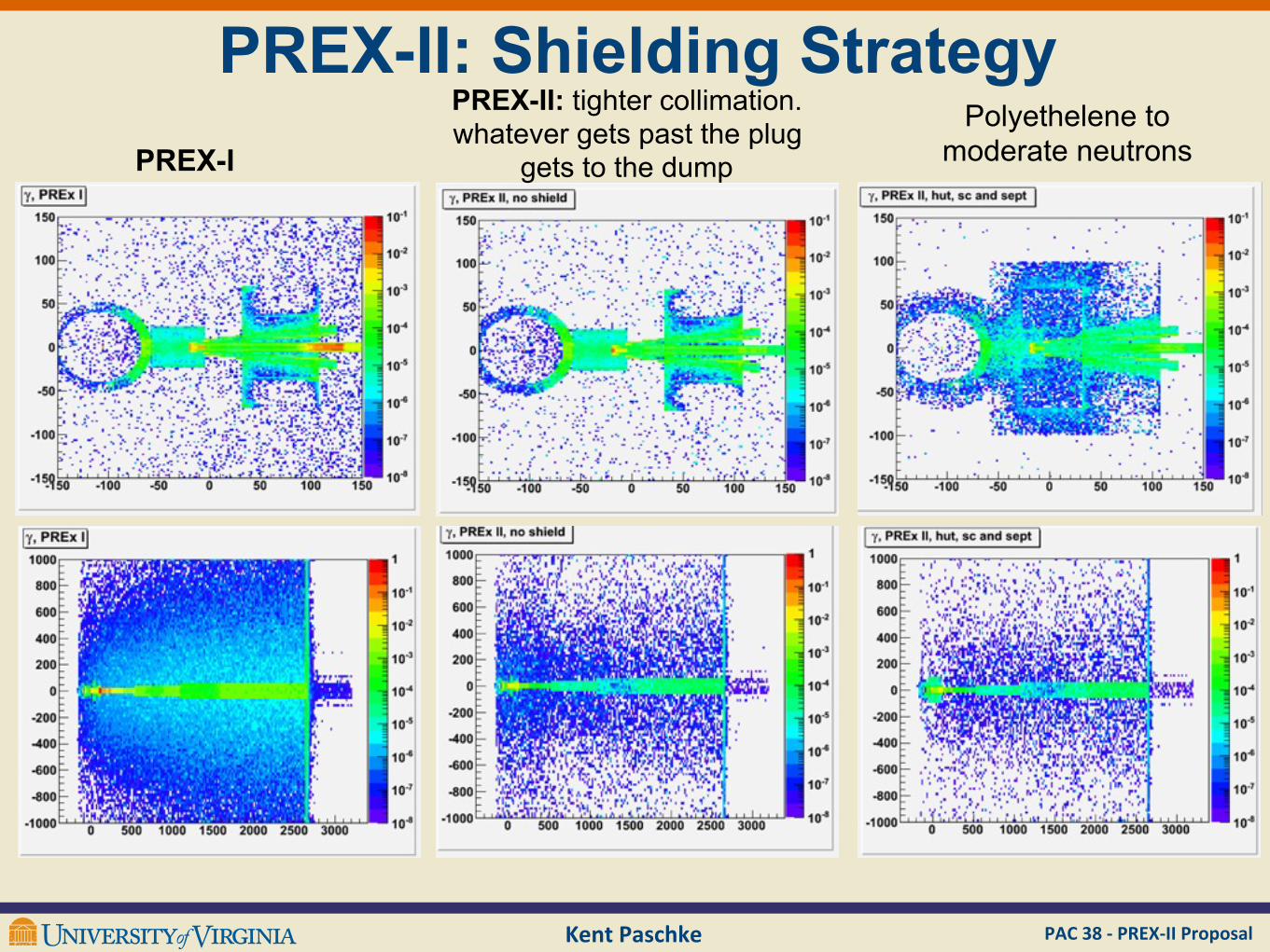
PREX-II: Shielding Strategy
neck down W plug, (cover 0.7-3o) so whatever gets past the plug gets to the dump
30cm thick Polyethelene hut to moderate neutrons
Still “just” a concept, but should be robust. Gaps matter only for solid angle
PAC 38 -‐ PREX-‐II ProposalKent Paschke
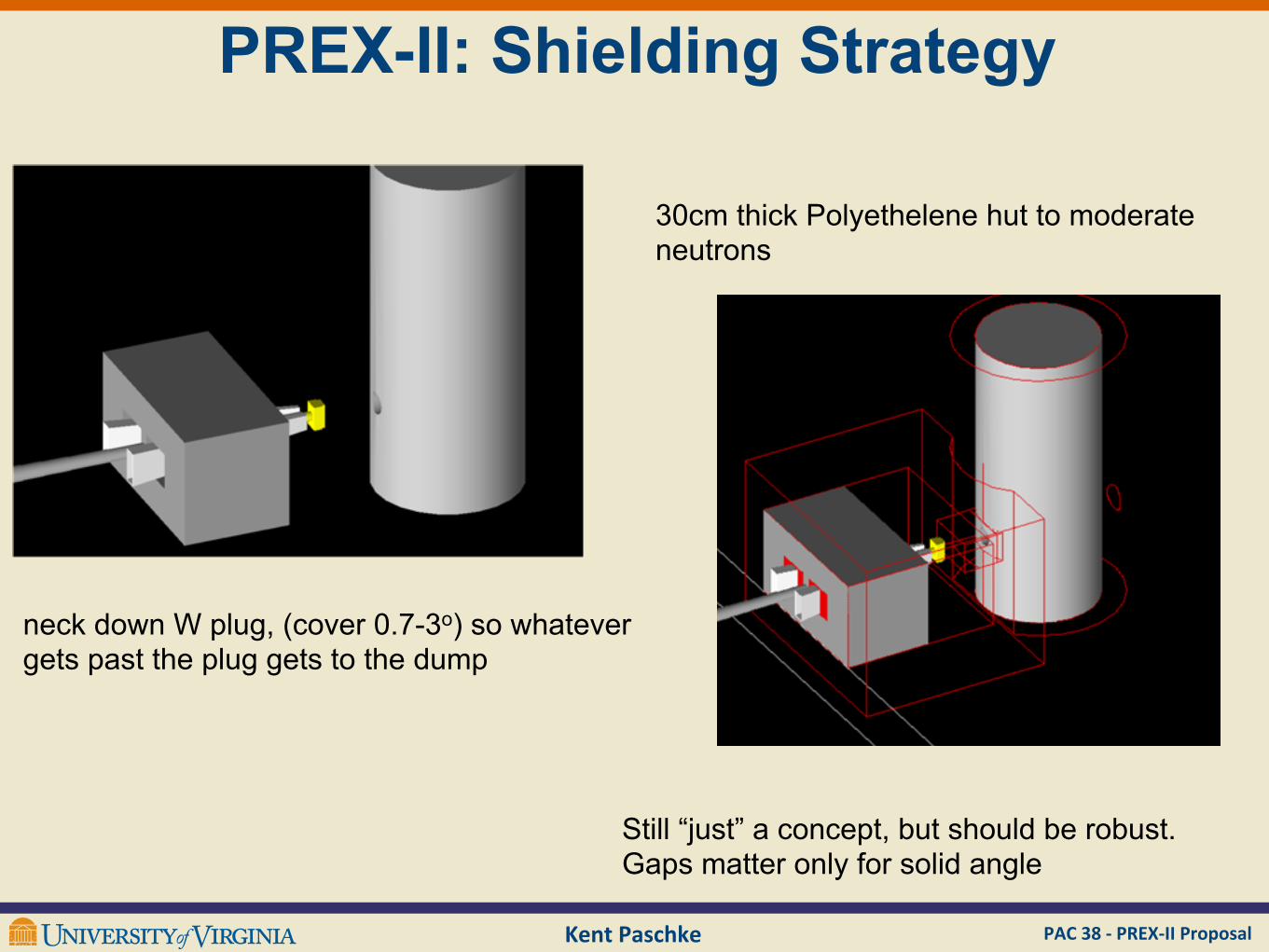
PREX-II: Shielding Strategy
neck down W plug, (cover 0.7-3o) so whatever gets past the plug gets to the dump
30cm thick Polyethelene hut to moderate neutrons
Still “just” a concept, but should be robust. Gaps matter only for solid angle
PAC 38 -‐ PREX-‐II ProposalKent Paschke
PREX-II: Shielding StrategyPREX-II: tighter collimation. whatever gets past the plug
gets to the dumpPREX-IPolyethelene to
moderate neutrons
PAC 38 -‐ PREX-‐II ProposalKent Paschke
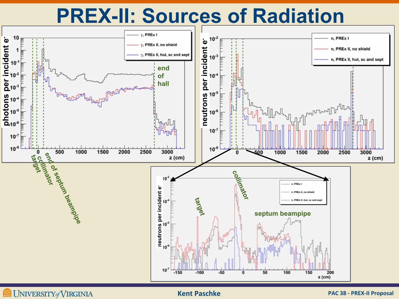
PREX-II: Sources of Radiation
neut
rons
per
inci
dent
e-
neut
rons
per
inci
dent
e-
phot
ons
per i
ncid
ent e
-
end of hall
targetcollim
atorend of septum
beampipe
target
collimator
septum beampipe
PAC 38 -‐ PREX-‐II ProposalKent Paschke
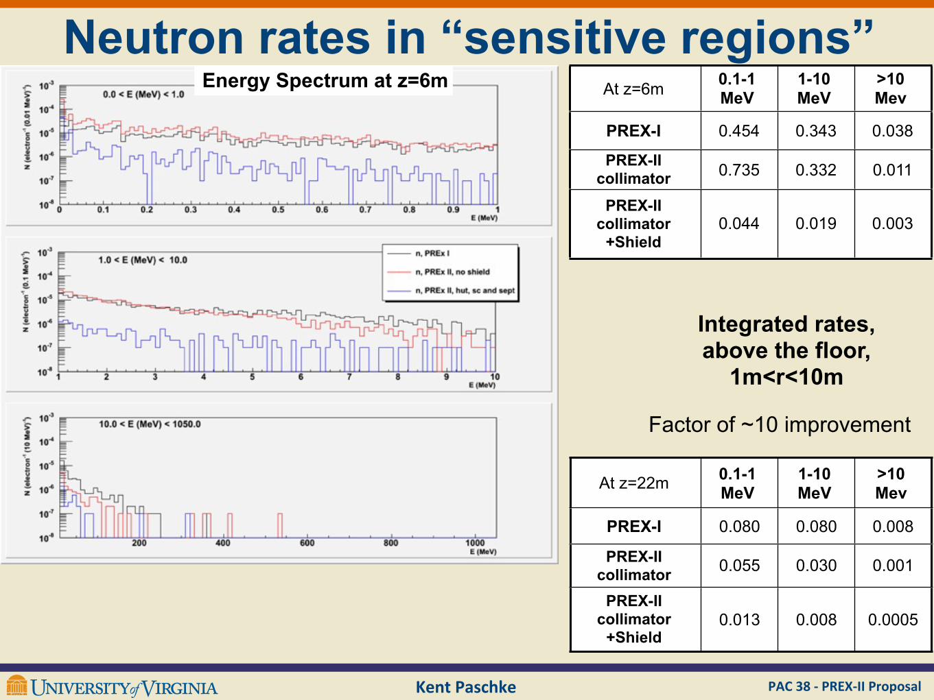
Neutron rates in “sensitive regions”At z=6m 0.1-1
MeV1-10 MeV
>10 Mev
PREX-I 0.454 0.343 0.038
PREX-II collimator 0.735 0.332 0.011
PREX-II collimator
+Shield0.044 0.019 0.003
At z=22m 0.1-1 MeV
1-10 MeV
>10 Mev
PREX-I 0.080 0.080 0.008
PREX-II collimator 0.055 0.030 0.001
PREX-II collimator
+Shield0.013 0.008 0.0005
Energy Spectrum at z=6m
Integrated rates, above the floor,
1m<r<10m
Factor of ~10 improvement
Kent Paschke PAC 38 -‐ PREX-‐II Proposal
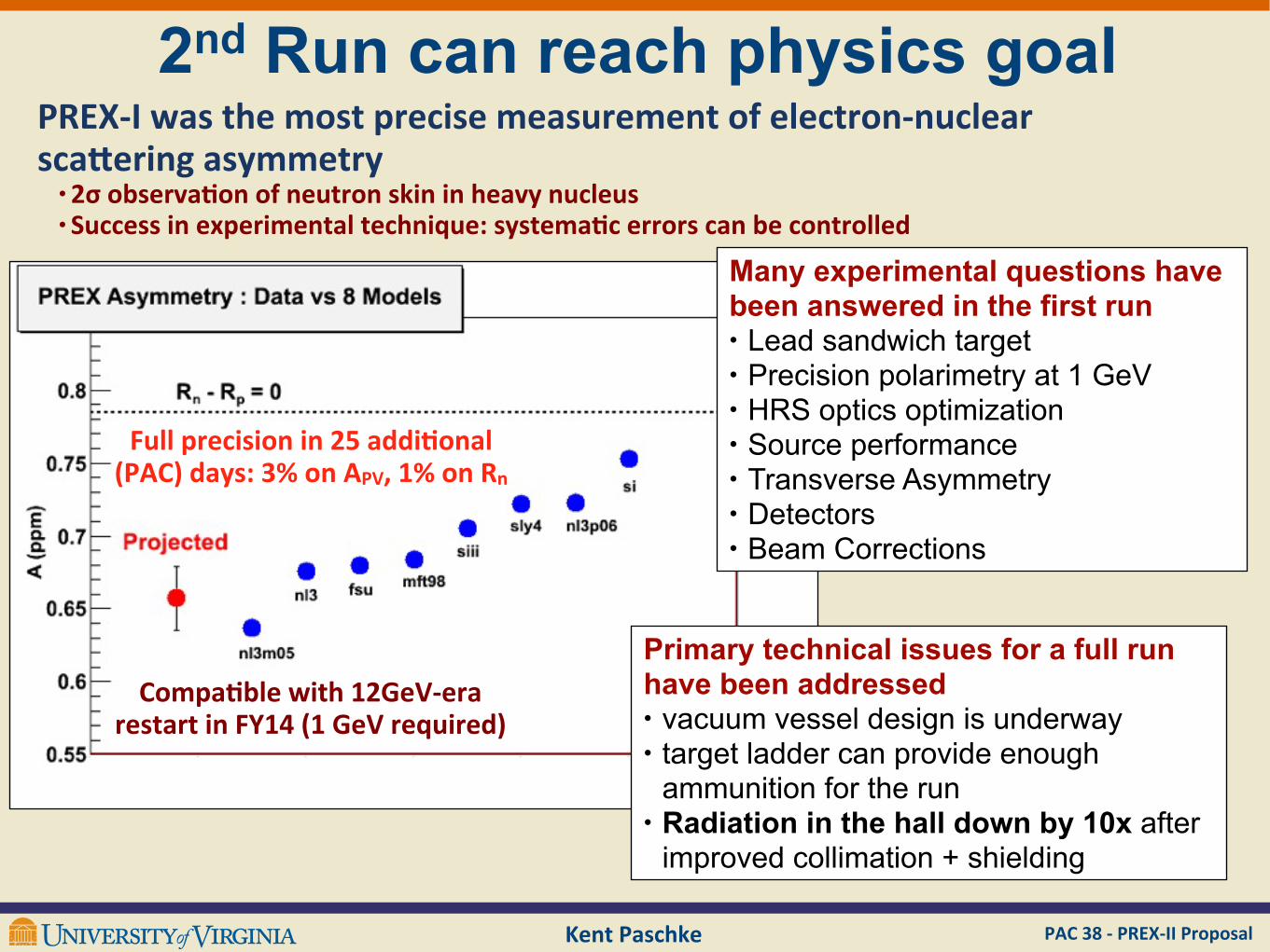
2nd Run can reach physics goal
Pb
Many experimental questions have been answered in the first run• Lead sandwich target• Precision polarimetry at 1 GeV• HRS optics optimization• Source performance• Transverse Asymmetry• Detectors• Beam Corrections
Primary technical issues for a full run have been addressed• vacuum vessel design is underway• target ladder can provide enough
ammunition for the run• Radiation in the hall down by 10x after
improved collimation + shielding
PREX-‐I was the most precise measurement of electron-‐nuclear scaSering asymmetry• 2σ observaBon of neutron skin in heavy nucleus• Success in experimental technique: systemaBc errors can be controlled
Full precision in 25 addiBonal (PAC) days: 3% on APV, 1% on Rn
CompaBble with 12GeV-‐era restart in FY14 (1 GeV required)