
Anna University vidyarthiplus.com
24
Anna University Department of Electrical and Electronics Engineering Notes on Lessons Class : VI semester B.E. Sub. EE2355 Design of Electrical Machines Faculty Name: A.Sangari, Senior Lecturer UNIT -1 INTRODUCTION Flux (Φ) = (MMF/ Reluctance) , Wb ; Reluctance(S) = (l/aμ) , A/Wb ; Permeance = ( 1/S) , Wb/A ; where l = length of the flux path, m ; A = area of cross section for the flux path, m 2 ; μ = permeability = μ o μ r ; μ o = absolute permeability = 4π x 10 -7 H/m and μ r = relative permeability. H = Ampere turns / m = MMF/ l = S Φ/ l = S Ba /l = (l/aμ) Ba/l = B/μ . or B = μH Series magnetic circuit : S = S 1 + S 2 +… Parallel magnetic circuit: Per= Per 1 + Per 2 +... Leakage Coeff. = total flux/useful flux; total flux = useful flux + leakage flux Expressions for reluctance: S g = l g / μ o l y s 1. Various configurations of slotting i) Smooth iron surface on both sides of the air gap : y s l = y s ii) slotted armature : y s l = y s - W s = W t (no fringing) iii) slotted armature : y s l = y s – K cs W s ; W s = slot width , W t = tooth width K cs = Carter’s Coefficient for slots depends on the ratio of slot opening /airgap length or the empirical relation is 1/ {1+ (5l g /W s )} If radial ventilating ducts are provided: L l = L – K cd n d W d where K cd = Carter’s Coefficient for ducts, vidyarthiplus.com
Transcript of Anna University vidyarthiplus.com
www.Vidyarthiplus.com
www.Vidyarthiplus.com Page 1
Anna University
Department of Electrical and Electronics Engineering
Notes on Lessons
Class : VI semester B.E. Sub. EE2355 Design of Electrical Machines
Faculty Name: A.Sangari, Senior Lecturer
UNIT -1
INTRODUCTION
Flux (Φ) = (MMF/ Reluctance) , Wb ; Reluctance(S) = (l/aµ) , A/Wb ;
Permeance = ( 1/S) , Wb/A ; where l = length of the flux path, m ;
A = area of cross section for the flux path, m2 ; µ = permeability = µo µ r ;
µo = absolute permeability = 4π x 10 -7
H/m and µ r = relative permeability.
H = Ampere turns / m = MMF/ l = S Φ/ l = S Ba /l = (l/aµ) Ba/l = B/µ .
or B = µH
Series magnetic circuit : S = S1 + S2+…
Parallel magnetic circuit: Per= Per1+ Per2+...
Leakage Coeff. = total flux/useful flux; total flux = useful flux + leakage flux
Expressions for reluctance: Sg = lg / µo l ys
1. Various configurations of slotting
i) Smooth iron surface on both sides of the air gap : ys
l = ys
ii) slotted armature : ys l = ys - Ws = Wt (no fringing)
iii) slotted armature : ys l = ys – Kcs Ws ; Ws = slot width , Wt = tooth width
Kcs = Carter’s Coefficient for slots depends on the ratio of slot opening /airgap length or
the empirical relation is 1/ {1+ (5lg /Ws )}
If radial ventilating ducts are provided: Ll = L – Kcd nd Wd
where Kcd = Carter’s Coefficient for ducts,
vidyarthiplus.com
www.Vidyarthiplus.com
www.Vidyarthiplus.com Page 2
nd = No.of ducts, Wd = width of each duct
If ducts are provided on the stator and on the rotor, then Kcd should be based
on half the air gap.
Considering the effect of both slotting and ducts, Kg ( gap contraction factor) = Kgs Kgd
where Kgs ={ ys / ys l } and Kgd ={L /L
l }
If slots are provided on both sides of the airgap, Kgs = Kgss Kgsr (ss and sr denoting stator
and rotor slots respectively).
MMF for airgap = H Kg lg ={ B/ µo }Kg lg = 8,00,000 B Kg lg .
Effect of Saliency : K f = Field form factor = Bave / Bg
= ψ = pole arc/pole pitch ;
pole pitch = πD/P ; Bave = Φ /( πDL/P)
_______________________________
2. MMF calculation for teeth
The calculation of MMF for producing flux in the Teeth of the machine is difficult
because :
i) the teeth are tapered when parallel sided slots are used and this results in variation in
the flux density over the depth of the tooth.
ii) the slots provide another parallel path for the flux flow, the teeth are normally worked
in saturation and hence µ r becomes low.
Following methods are usually employed for the calculation of MMF required for the
tapered teeth:-
i) Graphical method :ATt = Mean ord. x lt
Mean ord. is the mean ord. of “at” variation with tooth depth.
ii) Simpson’s rule :at mean = (at1 +4 at2 + at3)/6 A/m
iii) Bt1/3 method : ATt = at1/3 x lt ,
where at1/3 = MMF for corresponding to B at 1/3 rd
height from the narrow end.
3. Real and Apparent flux densities
Breal = Bapp - 4π x 10
-7 at (Ks –1) ;where Ks = Atotal / Airon = Lys / Li Wt
Specific Permeance : λ = Permeance per unit length or depth of the field.
vidyarthiplus.com
www.Vidyarthiplus.com
www.Vidyarthiplus.com Page 3
Parallel sided slot :
λ=µo[(h1/3ws) + (h2/ws )+ {2h3/ws+wo)} + (h4/wo) ]
4. Leakage reactance of transformers
Concentric winding
Total leakage reactance of the transformer referred to the primary =
Xp = 2πf µoTp2
(Lmt/Lc) {a+ (bp + bs)/3}
The per unit reactance can also be calculated as εx = Ip Xp /Vp ; where Ip , and Vp are
rated phase current and voltage respectively.
Sandwich winding:
Xp = πf µo(Tp2
/n)(Lmt/w) {a+ (bp + bs)/6}
5. Temperature rise calculations
Q = Power loss(heat produced ), J/s or W
G = weight of the active material of the Machine, kg
h = specific heat, J/kg-◦C
S = cooling surface area, m2
λ = specific heat dissipation, W/ m2
-◦C
c = 1/ λ = cooling coefficient, m2
-◦C / W
θm = final steady temperature rise, ◦C
The temperature of the machine rises when it is supplying load. As the temperature
rises, the heat is dissipated partly by conduction, partly by radiation and in most cases
largely by air cooling. The temperature rise curve is exponential in nature. Assuming the
theory of heating of homogeneous bodies ,
Heat developed = heat stored + heat dissipated
Q dt = Gh dθ + Sλθ dt ; solving → θ = θm ( 1- e –t/Th
) + θi e –t/Th
If the machine starts from cold, θi = 0 →θ = θm ( 1- e –t/Th
)
Th=heating time constant (time taken by the machine to attain 0.632 times θm) = Gh/Sλ Tc = cooling time constant (time taken by the machine to fall to 0.368 times θi)
Cooling curve is an exponentially falling curve.
vidyarthiplus.com
www.Vidyarthiplus.com
www.Vidyarthiplus.com Page 4
6. Rating of machines
IS: 4722-1968: specification for Rotating Electrical machinery:
1. continuous duty
2. short time duty (T‹‹ Th )
3. intermittent periodic duty
4. intermittent periodic duty with starting
5. intermittent periodic duty with starting and braking
6. continuous duty with intermittent periodic loading
7. continuous duty with starting and braking
8. continuous duty with periodic speed changes
7. Determination of motor rating
From the point of calculation of motor rating, the various duty cycles listed earlier, can
be broadly classified as
i) Continuous duty ii) Fluctuating duty and iii) Short time and intermittent duty.
Continuously duty motors work
These motors work with the same load through out the duty cycle.
Fluctuating loads
The motor is switched on for a period T1 and kept off for a period T2 .
To calculate the power rating of motors to be used with fluctuating loads,
the commonly used methods are :
i) Method of average losses ii) Equivalent current method
iii) Equivalent torque method.
Short time duty
The motor carries a load much higher than the rated continuous load for a short time.
The time for which the motor may be allowed to carry the short time higher load is th =
Th log {ph/ (ph – 1) }
where ph = θml / θm ; θm
l = final steady temperature that would be attained if the machine
is allowed to run indefinitely at its short time rating.
8. Cooling of rotating electrical machines
In most cases, the cooling electrical machines is carried out by air flow and this cooling
is called ventilation. In high speed machines such as turbo alternators, hydrogen is used
for cooling.
vidyarthiplus.com
www.Vidyarthiplus.com
www.Vidyarthiplus.com Page 5
Advantages of hydrogen cooling:
Compared with air, hydrogen has the following properties:-
i) (1/14) th
density thereby the windage losses and noise reduced ii) 14 times specific
heat and 1.5 times heat transfer leading to improved cooling iii) 7 times thermal
conductivity resulting in reduced temperature gradient iv) reduced corona effect v)
will not support combustion so long as the hyd /air mixture exceeds 3/1.
In operation, the fans mounted on the rotor circulate hydrogen through the ventilating
ducts and internally mounted gas coolers. The required gas pressure is maintained by a
regulator. The precaution to be observed is the stator frame must be gas tight and
explosion proof and oil film gas seals at the rotor shaft ends are essential.
Induced and Forced ventilation: In induced ventilation, the fan produces decreased air
pressure inside of the machine, causing air to be sucked into
the machine under the external atmospheric pressure ; and in the forced ventilation, the
air is forced into the fan by the fans mounted internally or externally.
The ventilation can also be classified as i) Radial, ii) axial and iii) combined radial and
axial.
9. Quantity of the cooling medium employed
Volume of air required = Va = (Q/cp θ) 10
3 x (760/H) x {( θi + 273)/273} V, m
3 /s
cp = 995 and V = 0.775 m3
assumed; then
Va = 0.78 (Q/ θ) x (760/H) x {( θi + 273)/273} , m3
The capacity of the fan required = Pfan = P Va /ηfan, W
Similar calculations can be made for the volume of hydrogen or air or oil used for
cooling the machine.
vidyarthiplus.com
www.Vidyarthiplus.com
www.Vidyarthiplus.com Page 6
UNIT II
DC MACHINES
D = stator bore or armature diameter, m
L = stator core length, m
p = number of poles
Z = Total numbers of armature conductors
Iz = current in each conductor(Ia/A) , A
E = induced EMF, V
P = machine rating (power output),kW
Pa = power developed by the armature, kW
Q = kVA rating of the machine
Φ = flux per pole, Wb
τ = pole pitch (π D/p), m
Total Electric loading = pΦ ; Total Magnetic loading = Iz Z
Specific Electric loading = ac = Iz Z
(amp.conductor/m) π D
Specific magnetic loading = Bave = pΦ
(Wb/m2
)
π DL
1. Output equation
Pa = E Ia x 10 -3
= (p/A)(ΦZN/60) Iz A 10 -3
= {π2 Bave ac x10
-3 }
D
2 L n = Co D
2 L n where Co = output coefficient
___________________________________
Generator: Pa = (P/η) – (FW & Iron losses) ; Motor : Pa = P + (FW & Iron losses)
For large machines : FW & Iron losses are neglected i.e.,
Pa = P/ η (Generator)
= P (Motor)
For small machines : FW & Iron losses can be taken as 1/3 rd
of the total losses. So, Pa = (P/η) – (1/3) P (1-η)/ η = P(2+ η)/(3 η) …generator
vidyarthiplus.com
www.Vidyarthiplus.com
www.Vidyarthiplus.com Page 7
= P + (1/3) P (1-η)/ η = P(1+2η)/(3 η) …motor
2. Choice of specific magnetic loading (Bave)
i) B max in the iron part of the magnetic circuit:
B max ≤ maximum allowable density
i.e., Bt = Bave Ys /wt (non-salient pole machines); Ys = slot-pitch and wt = tooth width.
&Bt = (Bave /ψ)Ys /wt (salient pole machines)
where ψ = pole arc /pole-pitch ratio.
If Ys =2 wt and ψ = 0.667 , then
Bt = 3 Bave : For example,if Bt is to be limited to 2.2 Wb/m2
,
Bave should excced 2.2/3 = 0.73 Wb/m2.
ii) Magnetizing current:
large Bave → high magnetizing current → large core loss
3. Choice of specific electric loading (ac)
i)Temperature rise(θ) θ depends on Q (losses),which in turn depends on ac.
Allowable θ depends on insulating material used.
ii) Cooling coefficient (C)
θ is also proportional to the cooling coefficient;
a machine with a better ventilation has a lower C and then higher ac can be used.
iii)Operating voltage (V)
In high voltage machines, the slot space factor, Sf is less and so only smaller ac can
be used. It also depends on the shape of the conductors, circular or rectangular in
cross section.
iv) Current Density (δ) choice of δ depends on cooling; higher C → higher value in the choice of ac.
4. Constraints in the design of DC machines
i) Peripheral speed,v ≤ 45 m/s
ii) Frequency of flux reversal, f ≤ 50 Hz
iii) Current per brush arm ≤ 400 A
iv) Armature MMF per pole ≤ 7000 A
vidyarthiplus.com

www.Vidyarthiplus.com
www.Vidyarthiplus.com Page 8
The MMF required for the airgap = 50% of the armature MMF and gap
contraction factor = 1.1.
The current per brush arm (Ib) = 2Ia/p , A
For square poles: L = ψ π D/p
In the design process, choose p based on f& Ib and then calculate D and L
5. Armature Design
Considerations in choice of number of armature slots :
i) mechanical difficulties ii) cooling of armature
iii) pulsation of flux iv) cost v)commutation (Slots/pole ≥ 9 )
vi) slot pitch (ys = 25 to 35 mm) vii) slot loading (Iz Zs ≤ 1500 Amp-cond)
viii) suitability of the winding – doublelayer Lap or wave )
Slot dimensions:
i) the slot area should accommodate the armature conductors and the required
insulation depending on the operating voltage ii) Bt1/3 ≤ 2.1 Wb/m2 iii) deep slots
cause eddy current losses iv) slot opening should be narrow to reduce the flux
pulsation and hence to reduce eddy current losses.
Armature voltage drop = Ia ra ;
ra = (Z/2) ρLmt /(a2 az ) ;
where Lmt = length of mean turn, m = 2L + 2.3τ +5ds ; a = no.of parallel paths and az =
area of each conductor, m2
.
6. Design of the Field system
Area of each pole (Ap) = Flux in the pole body / Flux density = cl φ / Bp
where cl = leakage coefficient
Width of the pole = Ap /Li ; where Li = net iron length = 0.9 L
Height of the pole(hf) chosen based on the MMF to be provided by the pole at full-load.
( ATf at full-load) /(ATArm. at full-load) =1.0 to 1.25
(to overcome armature reaction)
7. Tentative design of Field winding
Copper loss in the field winding = If
2 Rf
vidyarthiplus.com
www.Vidyarthiplus.com
www.Vidyarthiplus.com Page 9
= (δfaf)2
{ρLmt Tf}/af = δf2 ρLmt Tf af
= δf2 ρLmt Sf hfdf ; ………………….(1)
where df = depth of the pole winding. Tf = no.of turns in each field coil.
Permissible loss = S qf = 2Lmt hf qf ..(2)
_______
Equating (1) and (2) ; δf =104 √ qf / Sf df
MMF per metre of the field winding = ATf/ hf = If Tf /hf = δf (af Tf )/ hf
= δf Sf hfdf/hf = δf Sf df = Sqrt {2 qf Sf df /ρ}
8. Design of commutator and brushes
i) The number of commutator segments is equal to the number of coils.
ii)The commutator diameter Dc = 60 – 70 % of the armature diameter (D)
iii)Peripheral speed of commutator = π DcN/60 ≤ 20 m/s
iv) Pitch of the commutator segment = βc = π Dc/C ≥ 4.0 mm
(3.2 mm for the conducting portion and 0.8 mm for mica separator)
v) Distance between brush spindles = π Dc/p (25 – 30 cm)
vi) Length of the commutator = Lc = nb (wb + cb) + c1+ c2
where nb = number of brushes per brush arm, wb = width of the brush, cb =
clearance between brushes , c1 = clearance for staggering (10–30 mm), c2 = clearance
for end ply (10-25 mm).
vii) Current carried by each brush spindle
= Ib = 2Ia/p = Ab δb ; where Ab = nbwbtb
= total brush contact area ; δb = current density in the brushes (≈0.1 A/mm2).
nb is selected such that each brush does not carry more than about 70 A .
viii) The thickness of brush = (2-3) βc
ix) Com. surface area = Sc= π DcLc m2
x) Commutator surface losses:
1.brush contact loss = Wbc = VbIa ; Vb = brush contact drop ≈ 1.0 V/brush
vidyarthiplus.com
www.Vidyarthiplus.com
www.Vidyarthiplus.com Page 10
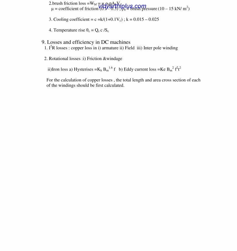
2.brush friction loss =Wbf = µ ρbpAbVc
µ = coefficient of friction (0.1 - 0.3) ; ρb = brush pressure (10 – 15 kN/ m2)
3. Cooling coefficient = c =k/(1+0.1Vc) ; k = 0.015 – 0.025
4. Temperature rise θc = Qc c /Sc
9. Losses and efficiency in DC machines 1. I2
R losses : copper loss in i) armature ii) Field iii) Inter pole winding
2. Rotational losses :i) Friction &windage
ii)Iron loss a) Hysterises =Kh Bm1.6
f b) Eddy current loss =Ke Bm2 f
2t2
For the calculation of copper losses , the total length and area cross section of each
of the windings should be first calculated.
vidyarthiplus.com
www.Vidyarthiplus.com
www.Vidyarthiplus.com Page 11
UNIT III
TRANSFORMERS
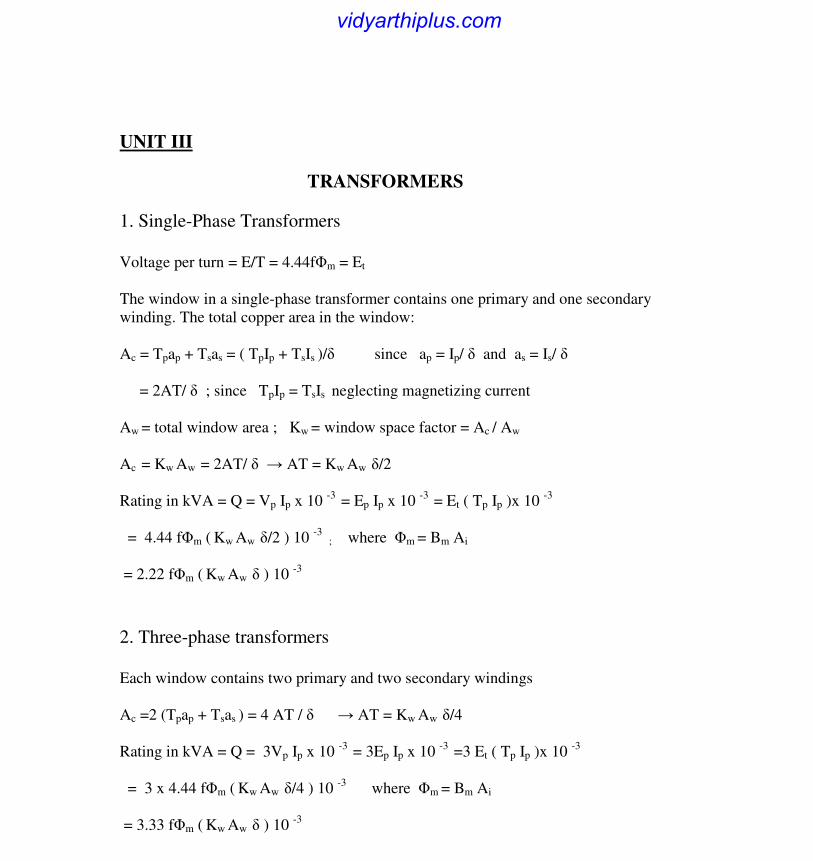
1. Single-Phase Transformers
Voltage per turn = E/T = 4.44fΦm = Et
The window in a single-phase transformer contains one primary and one secondary
winding. The total copper area in the window:
Ac = Tpap + Tsas = ( TpIp + TsIs )/δ since ap = Ip/ δ and as = Is/ δ
= 2AT/ δ ; since TpIp = TsIs neglecting magnetizing current
Aw = total window area ; Kw = window space factor = Ac / Aw
Ac = Kw Aw = 2AT/ δ → AT = Kw Aw δ/2
Rating in kVA = Q = Vp Ip x 10 -3
= Ep Ip x 10 -3
= Et ( Tp Ip )x 10 -3
= 4.44 fΦm ( Kw Aw δ/2 ) 10 -3
; where Φm = Bm Ai
= 2.22 fΦm ( Kw Aw δ ) 10 -3
2. Three-phase transformers
Each window contains two primary and two secondary windings
Ac =2 (Tpap + Tsas ) = 4 AT / δ → AT = Kw Aw δ/4
Rating in kVA = Q = 3Vp Ip x 10 -3
= 3Ep Ip x 10 -3
=3 Et ( Tp Ip )x 10 -3
= 3 x 4.44 fΦm ( Kw Aw δ/4 ) 10 -3
where Φm = Bm Ai
= 3.33 fΦm ( Kw Aw δ ) 10 -3
vidyarthiplus.com
www.Vidyarthiplus.com
www.Vidyarthiplus.com Page 12
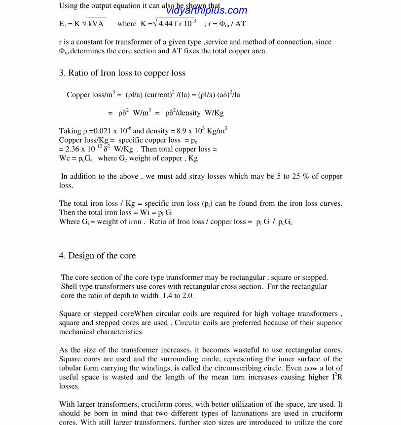
Using the output equation it can also be shown that
_____ __________
E t = K √ kVA where K =√ 4.44 f r 10 3 ; r = Φm / AT
r is a constant for transformer of a given type ,service and method of connection, since
Φm determines the core section and AT fixes the total copper area.
3. Ratio of Iron loss to copper loss
Copper loss/m
3 = (ρl/a) (current)
2 /(la) = (ρl/a) (aδ)2
/la
= ρδ2 W/m
3 = ρδ2
/density W/Kg
Taking ρ =0.021 x 10⁻⁶
and density = 8.9 x 10
3 Kg/m
3
Copper loss/Kg = specific copper loss = pc
= 2.36 x 10 12 δ2
W/Kg . Then total copper loss =
Wc = pcGc where Gc weight of copper , Kg
In addition to the above , we must add stray losses which may be 5 to 25 % of copper
loss.
The total iron loss / Kg = specific iron loss (pi) can be found from the iron loss curves.
Then the total iron loss = Wi = pi Gi
Where Gi = weight of iron . Ratio of Iron loss / copper loss = pi Gi / pcGc
4. Design of the core
The core section of the core type transformer may be rectangular , square or stepped.
Shell type transformers use cores with rectangular cross section. For the rectangular
core the ratio of depth to width 1.4 to 2.0.
Square or stepped coreWhen circular coils are required for high voltage transformers ,
square and stepped cores are used . Circular coils are preferred because of their superior
mechanical characteristics.
As the size of the transformer increases, it becomes wasteful to use rectangular cores.
Square cores are used and the surrounding circle, representing the inner surface of the
tubular form carrying the windings, is called the circumscribing circle. Even now a lot of
useful space is wasted and the length of the mean turn increases causing higher I2R
losses.
With larger transformers, cruciform cores, with better utilization of the space, are used. It
should be born in mind that two different types of laminations are used in cruciform
cores. With still larger transformers, further step sizes are introduced to utilize the core
vidyarthiplus.com

www.Vidyarthiplus.com
www.Vidyarthiplus.com Page 13
even more effectively. However, larger step sizes → larger number of lamination sizes →
higher labor cost.
Assuming a stacking factor for iron = 0.9 , Net core area / area of circumscribing circle
= 0.637 for square core and = 0.710 for stepped core with a= 0.851d , b= 0.526 d ;
where d = diameter of the circumscribing circle.
5. Choice Flux density and Current density( Bm and δ) Bm determines the core area.
Higher Bm → smaller area → smaller Lmt → saving in the cost of iron and copper. But
higher Bm increases the iron loss and temp rise. For Distribution transformer Bm = 1.1 to
1.35 Wb/m2
. For Power transformer Bm = 1.25 to 1.45 Wb/m2 .
The area of conductors for the primary and secondary windings determined after
choosing a suitable value for δ which depends on the method of cooling. 6. Types of Windings
i) Cylindrical winding with circular conductors
ii) Crossover winding with circular or rectangular conductors
iii) Continuous disc type winding with rectangular conductors
iv) Helical winding
7. Design of insulation
i) Electrical insulation: depends on the operating voltage
ii) Eddy current loss in the conductors and tank walls
iii) Mechanical considerations: high mechanical forces during fault
iv) Thermal considerations: depends on cooling
Major insulation : between windings and core (grounded)
Minor insulation ; between turns and layers
Materials : cotton thread, cotton tape, leatheriod paper, millinax paper etc.
8. Window dimensions
a = width of the largest samping ; d = dia of the circumscribing circle
D = distance between centres of adjacent limbs
Ww , Hw = width and height of the window ( length of the window)
Hy = height of the yoke
For core type: D = d + Ww ; W = D+a ; H = Hw + 2 Hy
vidyarthiplus.com
www.Vidyarthiplus.com
www.Vidyarthiplus.com Page 14
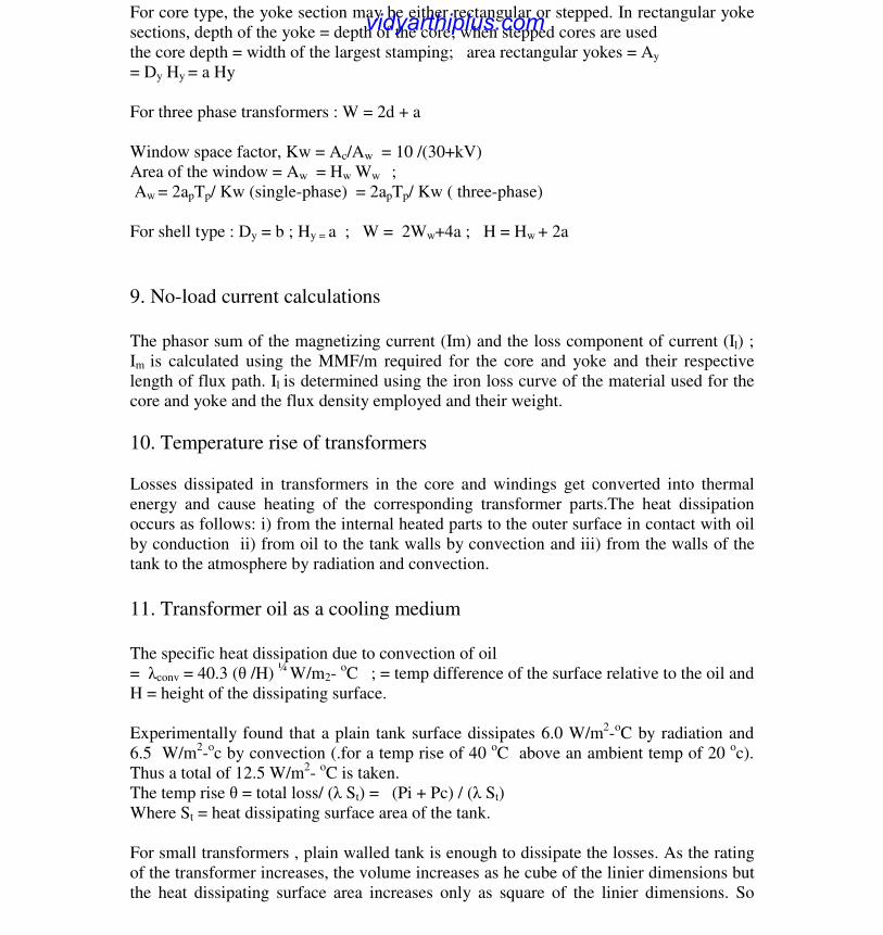
For core type, the yoke section may be either rectangular or stepped. In rectangular yoke
sections, depth of the yoke = depth of the core; when stepped cores are used
the core depth = width of the largest stamping; area rectangular yokes = Ay
= Dy Hy = a Hy
For three phase transformers : W = 2d + a
Window space factor, Kw = Ac/Aw = 10 /(30+kV)
Area of the window = Aw = Hw Ww ;
Aw = 2apTp/ Kw (single-phase) = 2apTp/ Kw ( three-phase)
For shell type : Dy = b ; Hy = a ; W = 2Ww+4a ; H = Hw + 2a
9. No-load current calculations
The phasor sum of the magnetizing current (Im) and the loss component of current (Il) ;
Im is calculated using the MMF/m required for the core and yoke and their respective
length of flux path. Il is determined using the iron loss curve of the material used for the
core and yoke and the flux density employed and their weight.
10. Temperature rise of transformers
Losses dissipated in transformers in the core and windings get converted into thermal
energy and cause heating of the corresponding transformer parts.The heat dissipation
occurs as follows: i) from the internal heated parts to the outer surface in contact with oil
by conduction ii) from oil to the tank walls by convection and iii) from the walls of the
tank to the atmosphere by radiation and convection.
11. Transformer oil as a cooling medium
The specific heat dissipation due to convection of oil
= λconv = 40.3 (θ /H) ¼
W/m2- oC ; = temp difference of the surface relative to the oil and
H = height of the dissipating surface.
Experimentally found that a plain tank surface dissipates 6.0 W/m2-oC by radiation and
6.5 W/m2-oc by convection (.for a temp rise of 40
oC above an ambient temp of 20
oc).
Thus a total of 12.5 W/m2-
oC is taken.
The temp rise θ = total loss/ (λ St) = (Pi + Pc) / (λ St)
Where St = heat dissipating surface area of the tank.
For small transformers , plain walled tank is enough to dissipate the losses. As the rating
of the transformer increases, the volume increases as he cube of the linier dimensions but
the heat dissipating surface area increases only as square of the linier dimensions. So
vidyarthiplus.com
www.Vidyarthiplus.com
www.Vidyarthiplus.com Page 15
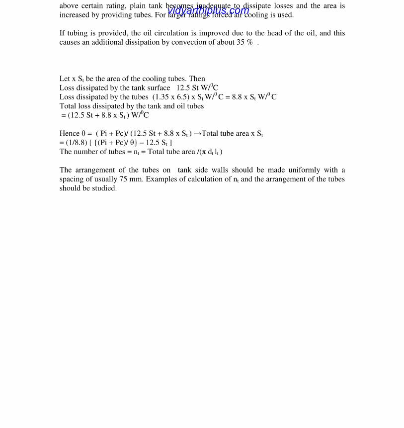
above certain rating, plain tank becomes inadequate to dissipate losses and the area is
increased by providing tubes. For larger ratings forced air cooling is used.
If tubing is provided, the oil circulation is improved due to the head of the oil, and this
causes an additional dissipation by convection of about 35 % .
Let x St be the area of the cooling tubes. Then
Loss dissipated by the tank surface 12.5 St W/0C
Loss dissipated by the tubes (1.35 x 6.5) x St W/0
C = 8.8 x St W/0
C
Total loss dissipated by the tank and oil tubes
= (12.5 St + 8.8 x St ) W/0C
Hence θ = ( Pi + Pc)/ (12.5 St + 8.8 x St ) →Total tube area x St
= (1/8.8) [ {(Pi + Pc)/ θ} – 12.5 St ]
The number of tubes = nt = Total tube area /(π dt lt )
The arrangement of the tubes on tank side walls should be made uniformly with a
spacing of usually 75 mm. Examples of calculation of nt and the arrangement of the tubes
should be studied.
vidyarthiplus.com
www.Vidyarthiplus.com
www.Vidyarthiplus.com Page 16
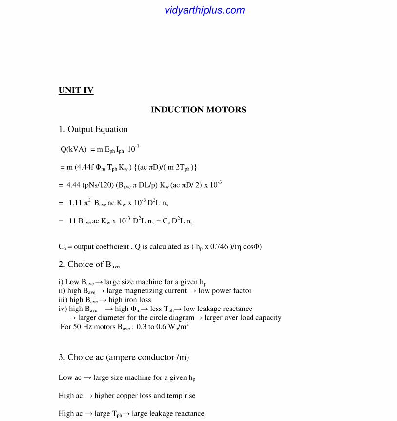
UNIT IV
INDUCTION MOTORS
1. Output Equation
Q(kVA) = m Eph Iph 10
-3
= m (4.44f Φm Tph Kw ) {(ac πD)/( m 2Tph )}
= 4.44 (pNs/120) (Bave π DL/p) Kw (ac πD/ 2) x 10-3
= 1.11 π2 Bave ac Kw x 10
-3 D
2L ns
= 11 Bave ac Kw x 10-3
D2L ns = Co D
2L ns
Co = output coefficient , Q is calculated as ( hp x 0.746 )/(η cosΦ)
2. Choice of Bave
i) Low Bave → large size machine for a given hp
ii) high Bave → large magnetizing current → low power factor
iii) high Bave → high iron loss
iv) high Bave → high Φm→ less Tph→ low leakage reactance
→ larger diameter for the circle diagram→ larger over load capacity
For 50 Hz motors Bave : 0.3 to 0.6 Wb/m2
3. Choice ac (ampere conductor /m)
Low ac → large size machine for a given hp
High ac → higher copper loss and temp rise
High ac → large Tph→ large leakage reactance
vidyarthiplus.com
www.Vidyarthiplus.com
www.Vidyarthiplus.com Page 17
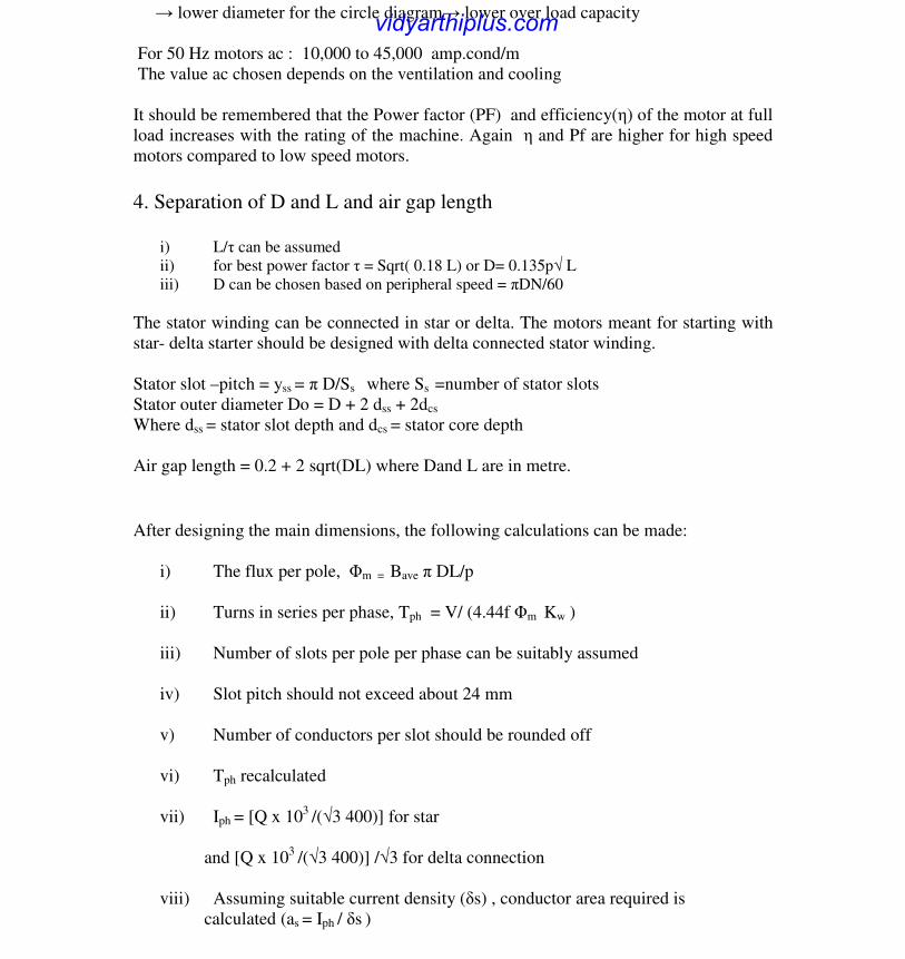
→ lower diameter for the circle diagram→ lower over load capacity
For 50 Hz motors ac : 10,000 to 45,000 amp.cond/m
The value ac chosen depends on the ventilation and cooling
It should be remembered that the Power factor (PF) and efficiency(η) of the motor at full
load increases with the rating of the machine. Again η and Pf are higher for high speed
motors compared to low speed motors.
4. Separation of D and L and air gap length
i) L/τ can be assumed
ii) for best power factor τ = Sqrt( 0.18 L) or D= 0.135p√ L
iii) D can be chosen based on peripheral speed = πDN/60
The stator winding can be connected in star or delta. The motors meant for starting with
star- delta starter should be designed with delta connected stator winding.
Stator slot –pitch = yss = π D/Ss where Ss =number of stator slots
Stator outer diameter Do = D + 2 dss + 2dcs
Where dss = stator slot depth and dcs = stator core depth
Air gap length = 0.2 + 2 sqrt(DL) where Dand L are in metre.
After designing the main dimensions, the following calculations can be made:
i) The flux per pole, Φm = Bave π DL/p
ii) Turns in series per phase, Tph = V/ (4.44f Φm Kw )
iii) Number of slots per pole per phase can be suitably assumed
iv) Slot pitch should not exceed about 24 mm
v) Number of conductors per slot should be rounded off
vi) Tph recalculated
vii) Iph = [Q x 103
/(√3 400)] for star
and [Q x 103
/(√3 400)] /√3 for delta connection
viii) Assuming suitable current density (δs) , conductor area required is
calculated (as = Iph / δs )
vidyarthiplus.com
www.Vidyarthiplus.com
www.Vidyarthiplus.com Page 18
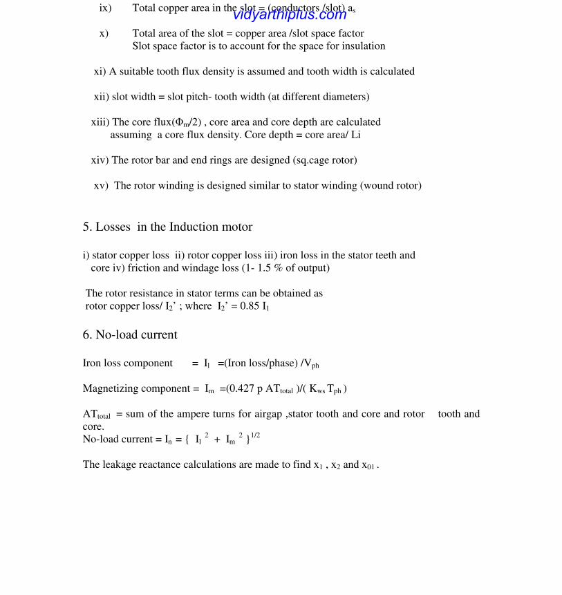
ix) Total copper area in the slot = (conductors /slot) as
x) Total area of the slot = copper area /slot space factor
Slot space factor is to account for the space for insulation
xi) A suitable tooth flux density is assumed and tooth width is calculated
xii) slot width = slot pitch- tooth width (at different diameters)
xiii) The core flux(Φm/2) , core area and core depth are calculated
assuming a core flux density. Core depth = core area/ Li
xiv) The rotor bar and end rings are designed (sq.cage rotor)
xv) The rotor winding is designed similar to stator winding (wound rotor)
5. Losses in the Induction motor
i) stator copper loss ii) rotor copper loss iii) iron loss in the stator teeth and
core iv) friction and windage loss (1- 1.5 % of output)
The rotor resistance in stator terms can be obtained as
rotor copper loss/ I2’ ; where I2’ = 0.85 I1
6. No-load current
Iron loss component = Il =(Iron loss/phase) /Vph
Magnetizing component = Im =(0.427 p ATtotal )/( Kws Tph )
ATtotal = sum of the ampere turns for airgap ,stator tooth and core and rotor tooth and
core.
No-load current = In = { Il 2
+ Im 2 }
1/2
The leakage reactance calculations are made to find x1 , x2 and x01 .
vidyarthiplus.com

www.Vidyarthiplus.com
www.Vidyarthiplus.com Page 19
UNIT V
SYNCHRONOUS MACHINES
1. Construction
Stationary armature, rotating field type of construction is preferred.
High speed alternators have non-salient pole rotor (Turbo alternators) and they have
either 2-pole or 4-pole. Slow speed alternators have salient pole rotor (water
wheel alternators) and they have more than 4 poles.
2. Output Equation
Q = m Eph Iph 10
-3
= 11 Bave ac Kw x 10-3
D2L ns = Co D
2L ns
Where Co = output coefficient
(see Unit -4 for derivation)
D and L are separated using L/τ ratio or maximum specified peripheral
speed of the rotor.
Damper winding is used for starting and damping rotor oscillations that occur during
sudden load changes.
3. Choice of specific magnetic loading (Bave)
i) High Bave → high flux density in the teeth and core →
high iron loss → higher temperature rise.
ii) high Bave → low Tph → low leakage reactance (Xl )
→ high short circuit current
vidyarthiplus.com
www.Vidyarthiplus.com
www.Vidyarthiplus.com Page 20
iii) In high voltage machines slot width required is more to accommodate
thicker insulation →smaller tooth width → small allowable Bave
iv) stability : Pmax =VE/Xs . Since high Bave gives low Tph and hence low Xl
Pmax increases and improves stability.
v) Parallel operation : Ps = (VE sinδ)/Xs ; where δ is the torque angle. So
low Xs gives higher value for the synchronizing power leading stable parallel
operation of synchronous generators.
Guide lines : Non-salient pole alternator : 0.54 – 0.65 Wb/m2
Salient – pole alternator : 0.52 – 0.65 Wb/m2
4. Choice of specific Electric loading (ac)
i) Copper loss and temperature rise: High value of ac → higher copper loss
leading high temperature rise. So choice of depends on the cooling method used.
ii) Operating voltage : High voltage machines require large insulation and so the slot
space available for conductors is reduced. So a lower value for ac has to be chosen.
iii) Synchronous reactance (Xs) : High value of ac results in high value of
Xs , and this leads to a) poor voltage regulation b) low steady state stability limit.
iv) Stray load losses increase with increase in ac.
Guide lines : Non-salient pole alternators : 50, 000 – 75,000 A/m
Salient pole alternators : 20,000 – 40,000 A/m
5. Short Circuit Ratio (SCR)
SCR = Field current required to produce rated voltage on opencircuit
Field current required to produce rated current on short circuit
= 1/ direct axis synchronous reactance = 1/Xd
Thus SCR is the reciprocal of Xd , if Xd is defined in p.u.value for rated voltage and
rated current. But Xd for a given load is affected by saturation conditions that then
exists, while SCR is specific and univalued for a given machine.
Non-salient pole alternators : 1- 1.5 ; Salient pole alternators : 0.5 – 0.7
Effect of SCR on machine performance
vidyarthiplus.com

www.Vidyarthiplus.com
www.Vidyarthiplus.com Page 21
i) Voltage regulation : A low SCR → high Xd → large voltage drop
→ poor voltage regulation..
ii) Parallel operation : A low SCR → high Xd → low synchronizing
power → parallel operation becomes difficult.
iii) Short circuit current : A low SCR → high Xd →low short circuit
current. But short circuit current can be limited by other means not
necessarily by keeping a low value of SCR.
iv) self excitation : Alternators feeding long transmission lines should
not be designed with small SCR as this would lead to large terminal
voltage on open circuit due to large capacitance currents.
Summarizing ,high value of SCR leads to i) high stability limit ii) low voltage
regulation iii) high short circuit current iv)large air gap
The present trend is to design machines with low value of SCR, this is due to the
recent development in fast acting control and excitation systems.
6. Length of airgap
The length of air gap very much influences the performance of a synchronous
machine. A large airgap offers a large reluctance to the path of the flux produced by
the armature MMF and thus reduces the effct of armature reaction. Thus a machine
with large airgap has a small Xd and so has
i)small regulation ii) high stability limit iii) high synchronizing power which makes
the machine less sensitive to load variations iv) better cooling at the gap surface v)
low magnetic noise and smaller unbalanced
magnetic pull.
But as the airgap length increases, a large value of Field MMF is required resulting in
increased cost of the machine.
7. Number of stator slots
Factors to be considered in the selection of number of slots :
1. Balanced 3-phase winding to be obtained
2. With large number of slots i)→large number of coils → increased
labor cost ii) cooling is improved iii) tooth ripples are less iv) Flux
density in the iron increases due to decreased tooth width.
Guide lines : Slot pitch (ys )≤ 25 mm for low voltage machines;
vidyarthiplus.com
www.Vidyarthiplus.com
www.Vidyarthiplus.com Page 22
≤ 40 mm for machines upto 6 kV ; ≤ 60 mm for machines upto 15 kV.
8. Methods of Eliminating Harmonics
By using i)distributed windings ii) fractional coil pitch
iii) fractional slot windings iv) skewing v) large airgap
Further calculations needed after determining D and L :
i) Flux per pole = Φ = Bave (π DL/p )
ii) Tph is calculated from the EMF equation taking Eph = Vph
iii) Iph = (Qx 103
) / √ 3 VL
iv) Armature MMF/pole = Ata = 2.7 Iph Tph Kw /p
v) Effective area per pole = 0.6 – 0.65 times actual area
9. Field Design (Salient poles)
Data needed for the design of the Field winding :
i) Flux density in the pole core ii)Winding depth (df)iii) Leakage factor (pole flux/gap
flux) iv) Field winding space factor (Sf) v) Power dissipation (qf) in W/m2 v) The
ratio of field MMF to armature MMF vi) Allow about 30 mm for insulation , flanges
and height of the pole shoe.
MMF per unit height of the winding = 104
Sqrt (Sf df qf )
Computer Aided Design of Electrical Machines
The process of design any electrical may be broadly divided into three major aspects: i)
Electrical design ii) Mechanical design iii) Thermal design. Even though, these
problems can be solved separately, there are many inter- related features.
The advantages of computer aided design are : i) The computer can handle large
volume of data to make a number of trial designs. And speed and accuracy of
calculations are very high. iii) It can be programmed to satisfying take logical decisions
iv) An optimized design with least cost and the required performance can be easily
obtained.
Generally any design method can be
i) analysis method ii) Synthesis method iii) Hybrid method
In the analysis method of design , a preliminary design is made by the designer
regarding the machine dimensions, materials and other constructional features and
these are given as input data to the computer and the performance quantities are
calculated. The designer examines the performance and accordingly alters the input
vidyarthiplus.com
www.Vidyarthiplus.com
www.Vidyarthiplus.com Page 23
data and then feed them to the computer again. The computer calculates the new
performance with the revised data. This process is repeated till the required
performance is achieved.
In the synthesis method, the required performance values are also given to the
computer as input. The computer through an iterative process alters the dimensions till
the required performance is obtained.
In the hybrid method, by some human intervention, a combination of analysis and
synthesis methods are adopted.
The method of design optimization using computers :
i) Choice of independent variables
ii) Variable transformation
iii) Forming the constraint functions for the performance
iv) Forming the objective function (OBJ)
v) Applying the minimization technique till the OBJ becomes with in the chosen
tolerance.
Example of Design of optimization of Induction Motors
The independent variables which has a significant effect on the performance are
stator core diameter, stator core length , stator core depth, stator slot depth, stator slot
width, rotor slot depth, rotor slot width, end ring depth, end ring width, . airgap length
and airgap flux density.
The other variables in the design are either taken as constants dased on the voltage and
power rating of the machine or they are in some way related to the above 11 variables.
During the course of optimization when the variables undergo incrementing or
decrementing, they should also be constrained to be with in practical ranges. This is
obtained by variable transformation. For example for airgap Xact = X tran + Lg min ;
where they respectively denote actual and transformed values and Lg min = minimum
airgap required.
Performance Specifications:
vidyarthiplus.com

www.Vidyarthiplus.com
www.Vidyarthiplus.com Page 24
1. Starting torque 2. maximum torque 3. Full- load power factor 4. full -load efficiency
5. full load slip 6.tooth and core flux densities 7. starting current 8. temperature rise 9.
cost of the machine.
Objective function
The objective function is formed by comparing the specified and calculated values of
the performance quantities at each iteration. Objective function minimization can be
carried out either using conventional methods such as Powel’s algorithm or
Rosenbrock method or the recent techniques such as Genetic algorithm.
It should be noted that the independent variables or the performance specifications vary
with the type of machine and its application.
vidyarthiplus.com