Analyses of Multimode Forming Process in a Microwave ...
7
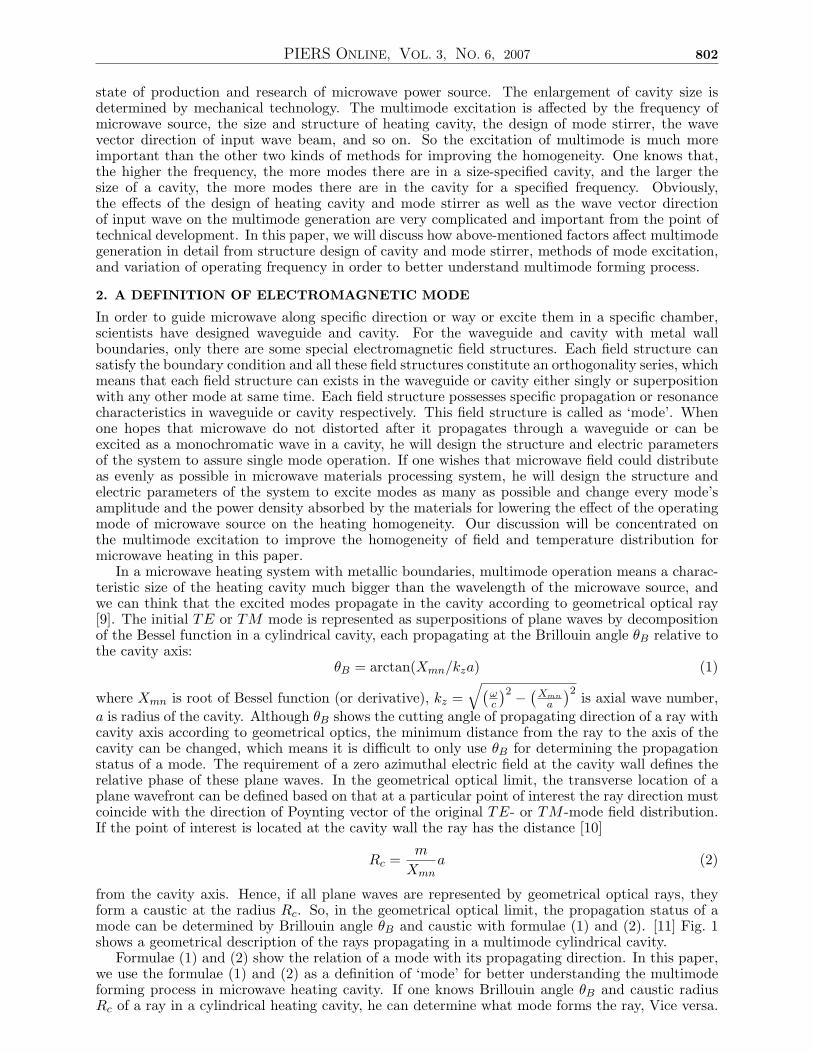
PIERS ONLINE, VOL. 3, NO. 6, 2007 801 Analyses of Multimode Forming Process in a Microwave-heating Cavity Jirun Luo Institute of Electronics, Chinese Academy of Science, Beijing 100080, China Abstract— A definition of electromagnetic mode, based on its propagation direction and the distance from the cavity axis with cutting angle θ B and caustic radius R c , is given and used to describe multimode forming process in a circular cylindrical cavity for explaining its effect on the quality of field homogeneity. And the effect of polygonal cylindrical cavity as well as the properties, size and shape of the material sample processed in the cavity on multimode forming process is also discussed. DOI: 10.2529/PIERS060819040945 1. INTRODUCTION Microwave heating of materials has been developing for over 40 years. The researches related to low processing temperature have led to the emergence of a lot of industrial facilities with microwave power sources at frequencies ≤ 2.45 GHz [1]. Many systems for microwave heating have been developed to improve the homogeneity of microwave field and temperature distribution, enhance the interaction efficiency of wave with materials, and pursue the industrial applications. The experimental methods vary from the coaxial lines and waveguide techniques used for decimeter wavelength to open quasi-optical cavities and interferometers exploited in millimeter wave range. The experimental activities [2–7] have been extended to microwave-assisted chemical synthesis, the surface processing of some specialized materials, and the sintering of structural and functional ceramics, composites, semiconductor materials, and even some conductive materials. A lot of the research results [2, 3] have shown good industrial perspective of microwave processing of materials from a technical viewpoint. In the early days, the researches were mainly done in a singe mode resonant cavity made of rectangular waveguide at the frequency of 2.45 GHz or 915 MHz. Usually, Q factor of this cavity is high, which results in that microwave energy concentrates on a small area, so the field around the heated sample is not uniform. Although the rotation and moving of the sample can appropriately improve the heating homogeneity with time average, the method can only used for the experimental study of small size samples. To improve the heating homogeneity in a larger area for satisfying the requirement of industrial applications, scientists enhance the cavity size. For a specific operating frequency, the increase of the cavity size means that more modes can exist in the cavity. So mode stirrer and some special geometrical transition structures have been used to excite these modes in the cavity through changing the wave vector direction of input microwave to promote the generation of different modes. To get sufficient homogeneity of the field and temperature distribution within samples in a multimode cavity, Patterson etal. [8] demand the characteristic size of the oven of about 12 meter if a frequency of 2.45 GHz is used. This is not only a too large size for manufacture, but also needs too high power for keeping enough microwave power density to heat the samples. So too large and complicated microwave system becomes a barrier for most industrial application. With the development of high power gyrotron, millimeter wave radiation has been utilized to improve the homogeneity of the field and temperature distribution inside the heated samples. Because the wavelength of millimeter wave is very short, the same homogeneity of the field and temperature distribution can be realized in a much smaller cavity, compared with that at the frequency of 2.45 GHz. In addition, the rotation and moving of the samples can also be used in the multimode cavity for further improving the homogeneity of the field and temperature distribution inside the heated samples with time average. Based on above-mentioned description, increasing frequency, enlarging cavity size, rotating and moving the samples, and exciting multimode in the cavity can all improve the homogeneity of the field and temperature distribution. Except for the rotation and moving of the samples, the other three kinds of methods are mutually correlative. The increase of frequency is dependent on the
Transcript of Analyses of Multimode Forming Process in a Microwave ...
PIERS ONLINE, VOL. 3, NO. 6, 2007 801
Analyses of Multimode Forming Process in a Microwave-heatingCavity
Jirun LuoInstitute of Electronics, Chinese Academy of Science, Beijing 100080, China
Abstract— A definition of electromagnetic mode, based on its propagation direction and thedistance from the cavity axis with cutting angle θB and caustic radius Rc, is given and used todescribe multimode forming process in a circular cylindrical cavity for explaining its effect onthe quality of field homogeneity. And the effect of polygonal cylindrical cavity as well as theproperties, size and shape of the material sample processed in the cavity on multimode formingprocess is also discussed.
DOI: 10.2529/PIERS060819040945
1. INTRODUCTION
Microwave heating of materials has been developing for over 40 years. The researches related to lowprocessing temperature have led to the emergence of a lot of industrial facilities with microwavepower sources at frequencies ≤ 2.45GHz [1]. Many systems for microwave heating have beendeveloped to improve the homogeneity of microwave field and temperature distribution, enhancethe interaction efficiency of wave with materials, and pursue the industrial applications. Theexperimental methods vary from the coaxial lines and waveguide techniques used for decimeterwavelength to open quasi-optical cavities and interferometers exploited in millimeter wave range.The experimental activities [2–7] have been extended to microwave-assisted chemical synthesis,the surface processing of some specialized materials, and the sintering of structural and functionalceramics, composites, semiconductor materials, and even some conductive materials. A lot of theresearch results [2, 3] have shown good industrial perspective of microwave processing of materialsfrom a technical viewpoint.
In the early days, the researches were mainly done in a singe mode resonant cavity made ofrectangular waveguide at the frequency of 2.45 GHz or 915MHz. Usually, Q factor of this cavity ishigh, which results in that microwave energy concentrates on a small area, so the field around theheated sample is not uniform. Although the rotation and moving of the sample can appropriatelyimprove the heating homogeneity with time average, the method can only used for the experimentalstudy of small size samples. To improve the heating homogeneity in a larger area for satisfying therequirement of industrial applications, scientists enhance the cavity size. For a specific operatingfrequency, the increase of the cavity size means that more modes can exist in the cavity. Somode stirrer and some special geometrical transition structures have been used to excite thesemodes in the cavity through changing the wave vector direction of input microwave to promotethe generation of different modes. To get sufficient homogeneity of the field and temperaturedistribution within samples in a multimode cavity, Patterson et al. [8] demand the characteristicsize of the oven of about 12 meter if a frequency of 2.45 GHz is used. This is not only a too largesize for manufacture, but also needs too high power for keeping enough microwave power densityto heat the samples. So too large and complicated microwave system becomes a barrier for mostindustrial application. With the development of high power gyrotron, millimeter wave radiationhas been utilized to improve the homogeneity of the field and temperature distribution inside theheated samples. Because the wavelength of millimeter wave is very short, the same homogeneityof the field and temperature distribution can be realized in a much smaller cavity, compared withthat at the frequency of 2.45 GHz. In addition, the rotation and moving of the samples can also beused in the multimode cavity for further improving the homogeneity of the field and temperaturedistribution inside the heated samples with time average.
Based on above-mentioned description, increasing frequency, enlarging cavity size, rotating andmoving the samples, and exciting multimode in the cavity can all improve the homogeneity of thefield and temperature distribution. Except for the rotation and moving of the samples, the otherthree kinds of methods are mutually correlative. The increase of frequency is dependent on the
PIERS ONLINE, VOL. 3, NO. 6, 2007 802
state of production and research of microwave power source. The enlargement of cavity size isdetermined by mechanical technology. The multimode excitation is affected by the frequency ofmicrowave source, the size and structure of heating cavity, the design of mode stirrer, the wavevector direction of input wave beam, and so on. So the excitation of multimode is much moreimportant than the other two kinds of methods for improving the homogeneity. One knows that,the higher the frequency, the more modes there are in a size-specified cavity, and the larger thesize of a cavity, the more modes there are in the cavity for a specified frequency. Obviously,the effects of the design of heating cavity and mode stirrer as well as the wave vector directionof input wave on the multimode generation are very complicated and important from the point oftechnical development. In this paper, we will discuss how above-mentioned factors affect multimodegeneration in detail from structure design of cavity and mode stirrer, methods of mode excitation,and variation of operating frequency in order to better understand multimode forming process.
2. A DEFINITION OF ELECTROMAGNETIC MODE
In order to guide microwave along specific direction or way or excite them in a specific chamber,scientists have designed waveguide and cavity. For the waveguide and cavity with metal wallboundaries, only there are some special electromagnetic field structures. Each field structure cansatisfy the boundary condition and all these field structures constitute an orthogonality series, whichmeans that each field structure can exists in the waveguide or cavity either singly or superpositionwith any other mode at same time. Each field structure possesses specific propagation or resonancecharacteristics in waveguide or cavity respectively. This field structure is called as ‘mode’. Whenone hopes that microwave do not distorted after it propagates through a waveguide or can beexcited as a monochromatic wave in a cavity, he will design the structure and electric parametersof the system to assure single mode operation. If one wishes that microwave field could distributeas evenly as possible in microwave materials processing system, he will design the structure andelectric parameters of the system to excite modes as many as possible and change every mode’samplitude and the power density absorbed by the materials for lowering the effect of the operatingmode of microwave source on the heating homogeneity. Our discussion will be concentrated onthe multimode excitation to improve the homogeneity of field and temperature distribution formicrowave heating in this paper.
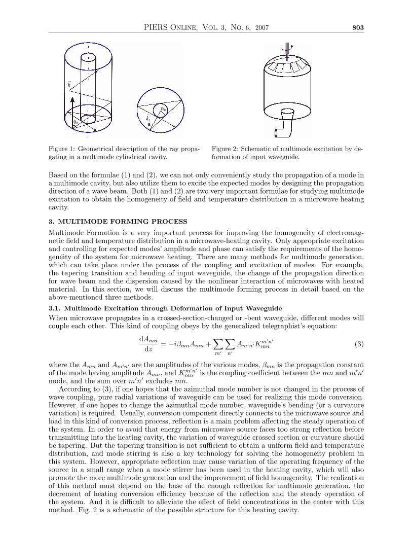
In a microwave heating system with metallic boundaries, multimode operation means a charac-teristic size of the heating cavity much bigger than the wavelength of the microwave source, andwe can think that the excited modes propagate in the cavity according to geometrical optical ray[9]. The initial TE or TM mode is represented as superpositions of plane waves by decompositionof the Bessel function in a cylindrical cavity, each propagating at the Brillouin angle θB relative tothe cavity axis:
θB = arctan(Xmn/kza) (1)
where Xmn is root of Bessel function (or derivative), kz =√(
ωc
)2 − (Xmn
a
)2is axial wave number,
a is radius of the cavity. Although θB shows the cutting angle of propagating direction of a ray withcavity axis according to geometrical optics, the minimum distance from the ray to the axis of thecavity can be changed, which means it is difficult to only use θB for determining the propagationstatus of a mode. The requirement of a zero azimuthal electric field at the cavity wall defines therelative phase of these plane waves. In the geometrical optical limit, the transverse location of aplane wavefront can be defined based on that at a particular point of interest the ray direction mustcoincide with the direction of Poynting vector of the original TE- or TM -mode field distribution.If the point of interest is located at the cavity wall the ray has the distance [10]
Rc =m
Xmna (2)
from the cavity axis. Hence, if all plane waves are represented by geometrical optical rays, theyform a caustic at the radius Rc. So, in the geometrical optical limit, the propagation status of amode can be determined by Brillouin angle θB and caustic with formulae (1) and (2). [11] Fig. 1shows a geometrical description of the rays propagating in a multimode cylindrical cavity.
Formulae (1) and (2) show the relation of a mode with its propagating direction. In this paper,we use the formulae (1) and (2) as a definition of ‘mode’ for better understanding the multimodeforming process in microwave heating cavity. If one knows Brillouin angle θB and caustic radiusRc of a ray in a cylindrical heating cavity, he can determine what mode forms the ray, Vice versa.
PIERS ONLINE, VOL. 3, NO. 6, 2007 803
k
r
k
r
at
Rc
Bθ
Figure 1: Geometrical description of the ray propa-gating in a multimode cylindrical cavity.
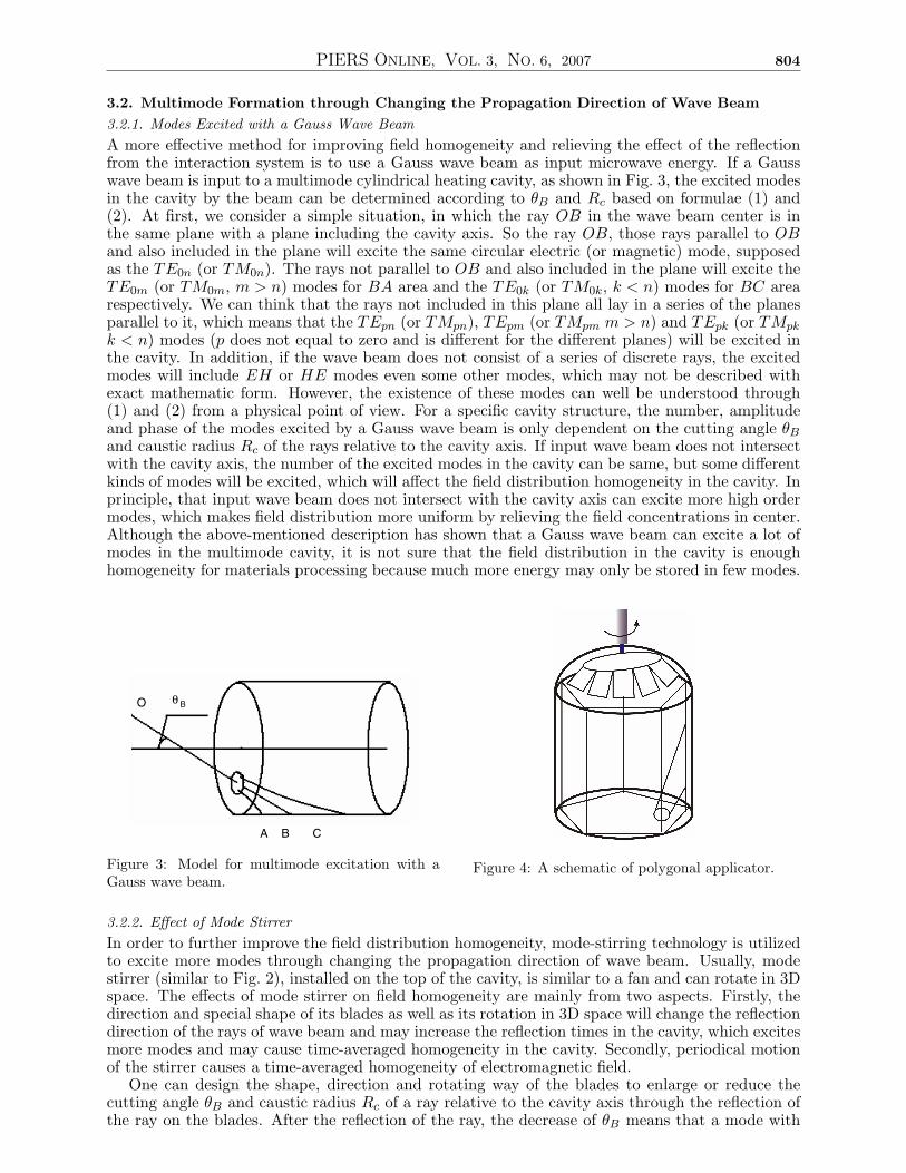
Figure 2: Schematic of multimode excitation by de-formation of input waveguide.
Based on the formulae (1) and (2), we can not only conveniently study the propagation of a mode ina multimode cavity, but also utilize them to excite the expected modes by designing the propagationdirection of a wave beam. Both (1) and (2) are two very important formulae for studying multimodeexcitation to obtain the homogeneity of field and temperature distribution in a microwave heatingcavity.
3. MULTIMODE FORMING PROCESS
Multimode Formation is a very important process for improving the homogeneity of electromag-netic field and temperature distribution in a microwave-heating cavity. Only appropriate excitationand controlling for expected modes’ amplitude and phase can satisfy the requirements of the homo-geneity of the system for microwave heating. There are many methods for multimode generation,which can take place under the process of the coupling and excitation of modes. For example,the tapering transition and bending of input waveguide, the change of the propagation directionfor wave beam and the dispersion caused by the nonlinear interaction of microwaves with heatedmaterial. In this section, we will discuss the multimode forming process in detail based on theabove-mentioned three methods.3.1. Multimode Excitation through Deformation of Input WaveguideWhen microwave propagates in a crossed-section-changed or -bent waveguide, different modes willcouple each other. This kind of coupling obeys by the generalized telegraphist’s equation:
dAmn
dz= −iβmnAmn +
∑
m′
∑
n′
Am′n′Km′n′mn (3)
where the Amn and Am′n′ are the amplitudes of the various modes, βmn is the propagation constantof the mode having amplitude Amn, and Km′n′
mn is the coupling coefficient between the mn and m′n′mode, and the sum over m′n′ excludes mn.
According to (3), if one hopes that the azimuthal mode number is not changed in the process ofwave coupling, pure radial variations of waveguide can be used for realizing this mode conversion.However, if one hopes to change the azimuthal mode number, waveguide’s bending (or a curvaturevariation) is required. Usually, conversion component directly connects to the microwave source andload in this kind of conversion process, reflection is a main problem affecting the steady operation ofthe system. In order to avoid that energy from microwave source faces too strong reflection beforetransmitting into the heating cavity, the variation of waveguide crossed section or curvature shouldbe tapering. But the tapering transition is not sufficient to obtain a uniform field and temperaturedistribution, and mode stirring is also a key technology for solving the homogeneity problem inthis system. However, appropriate reflection may cause variation of the operating frequency of thesource in a small range when a mode stirrer has been used in the heating cavity, which will alsopromote the more multimode generation and the improvement of field homogeneity. The realizationof this method must depend on the base of the enough reflection for multimode generation, thedecrement of heating conversion efficiency because of the reflection and the steady operation ofthe system. And it is difficult to alleviate the effect of field concentrations in the center with thismethod. Fig. 2 is a schematic of the possible structure for this heating cavity.
PIERS ONLINE, VOL. 3, NO. 6, 2007 804
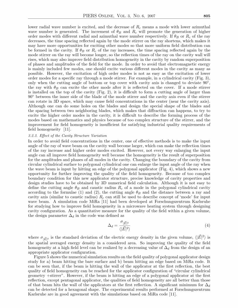
3.2. Multimode Formation through Changing the Propagation Direction of Wave Beam3.2.1. Modes Excited with a Gauss Wave BeamA more effective method for improving field homogeneity and relieving the effect of the reflectionfrom the interaction system is to use a Gauss wave beam as input microwave energy. If a Gausswave beam is input to a multimode cylindrical heating cavity, as shown in Fig. 3, the excited modesin the cavity by the beam can be determined according to θB and Rc based on formulae (1) and(2). At first, we consider a simple situation, in which the ray OB in the wave beam center is inthe same plane with a plane including the cavity axis. So the ray OB, those rays parallel to OBand also included in the plane will excite the same circular electric (or magnetic) mode, supposedas the TE0n (or TM0n). The rays not parallel to OB and also included in the plane will excite theTE0m (or TM0m, m > n) modes for BA area and the TE0k (or TM0k, k < n) modes for BC arearespectively. We can think that the rays not included in this plane all lay in a series of the planesparallel to it, which means that the TEpn (or TMpn), TEpm (or TMpm m > n) and TEpk (or TMpk
k < n) modes (p does not equal to zero and is different for the different planes) will be excited inthe cavity. In addition, if the wave beam does not consist of a series of discrete rays, the excitedmodes will include EH or HE modes even some other modes, which may not be described withexact mathematic form. However, the existence of these modes can well be understood through(1) and (2) from a physical point of view. For a specific cavity structure, the number, amplitudeand phase of the modes excited by a Gauss wave beam is only dependent on the cutting angle θB
and caustic radius Rc of the rays relative to the cavity axis. If input wave beam does not intersectwith the cavity axis, the number of the excited modes in the cavity can be same, but some differentkinds of modes will be excited, which will affect the field distribution homogeneity in the cavity. Inprinciple, that input wave beam does not intersect with the cavity axis can excite more high ordermodes, which makes field distribution more uniform by relieving the field concentrations in center.Although the above-mentioned description has shown that a Gauss wave beam can excite a lot ofmodes in the multimode cavity, it is not sure that the field distribution in the cavity is enoughhomogeneity for materials processing because much more energy may only be stored in few modes.
O
A B C
θB
Figure 3: Model for multimode excitation with aGauss wave beam.
Figure 4: A schematic of polygonal applicator.
3.2.2. Effect of Mode StirrerIn order to further improve the field distribution homogeneity, mode-stirring technology is utilizedto excite more modes through changing the propagation direction of wave beam. Usually, modestirrer (similar to Fig. 2), installed on the top of the cavity, is similar to a fan and can rotate in 3Dspace. The effects of mode stirrer on field homogeneity are mainly from two aspects. Firstly, thedirection and special shape of its blades as well as its rotation in 3D space will change the reflectiondirection of the rays of wave beam and may increase the reflection times in the cavity, which excitesmore modes and may cause time-averaged homogeneity in the cavity. Secondly, periodical motionof the stirrer causes a time-averaged homogeneity of electromagnetic field.
One can design the shape, direction and rotating way of the blades to enlarge or reduce thecutting angle θB and caustic radius Rc of a ray relative to the cavity axis through the reflection ofthe ray on the blades. After the reflection of the ray, the decrease of θB means that a mode with
PIERS ONLINE, VOL. 3, NO. 6, 2007 805
lower radial wave number is excited, and the decrease of Rc means a mode with lower azimuthalwave number is generated. The increment of θB and Rc will promote the generation of higherorder modes with different radial and azimuthal wave number respectively. If θB or Rc of the raydecreases, the time spacing reflected again by the mode stirrer on the ray shortens, which makes itmay have more opportunities for exciting other modes so that more uniform field distribution canbe formed in the cavity. If θB or Rc of the ray increases, the time spacing reflected again by themode stirrer on the ray will become longer, so the reflection times of the ray on the cavity wall willrises, which may also improve field distribution homogeneity in the cavity by random superpositionof phases and amplitudes of the field for the mode. In order to avoid that electromagnetic energyis mainly included few modes, one should excite various different modes in the cavity as many aspossible. However, the excitation of high order modes is not as easy as the excitation of lowerorder modes for a specific ray through a mode stirrer. For example, in a cylindrical cavity (Fig. 3),only when the cutting angle of bottom or top cover with cavity axis is changed to deviate 90◦,the ray with θB can excite the other mode after it is reflected on the cover. If a mode stirreris installed on the top of the cavity (Fig. 2), it is difficult to form a cutting angle of larger than90◦ between the inner side of the blade of the mode stirrer and the cavity axis even if the stirrercan rotate in 3D space, which may cause field concentrations in the center (near the cavity axis).Although one can do some holes on the blades and design the special shape of the blades andthe spacing between two neighboring blades, which makes that diffraction can happens, to try toexcite the higher order modes in the cavity, it is difficult to describe the forming process of themodes based on mathematics and physics because of too complex structure of the stirrer, and theimprovement for field homogeneity is insufficient for satisfying industrial quality requirements offield homogeneity [11].3.2.3. Effect of the Cavity Structure VariationIn order to avoid field concentrations in the center, one of effective methods is to make the inputangle of the ray of wave beam on the cavity wall become larger, which can make the reflection timesof the ray increase and higher order modes excited. However, not every way enlarging the inputangle can all improve field homogeneity well because the homogeneity is the result of superpositionfor the amplitudes and phases of all modes in the cavity. Changing the boundary of the cavity fromcircular cylindrical surface to polygonal cylindrical one can enlarge the input angle of the ray whenthe wave beam is input by hitting an edge of the polygonal applicator (Fig. 4), which shows a newopportunity for further improving the quality of the field homogeneity. Because of too complexboundary condition for this new applicator structure, precise knowledge of cavity properties anddesign studies have to be obtained by 3D numerical field calculation. Although it is not easy todefine the cutting angle θB and caustic radius Rc of a mode in the polygonal cylindrical cavityaccording to the formulae (1) and (2), the cutting angle θB and the distance between a ray andcavity axis (similar to caustic radius) Rc can still be used to describe concept of ‘mode’ for inputwave beam. A simulation code MiRa [11] had been developed at Forschungszentrum Karlsruhefor studying how to improve field homogeneity in a microwave heating system through designingcavity configuration. As a quantitative measure for the quality of the field within a given volume,the design parameter ∆d in the code was defined as
∆d =σ| ~E|2
〈| ~E|2〉(4)
where σ| ~E|2 is the standard deviation of the electric energy density in the given volume, 〈| ~E|2〉 isthe spatial averaged energy density in a considered area. So improving the quality of the fieldhomogeneity at a high field level can be realized by a decreasing value of ∆d from the design of anappropriate applicator configuration.
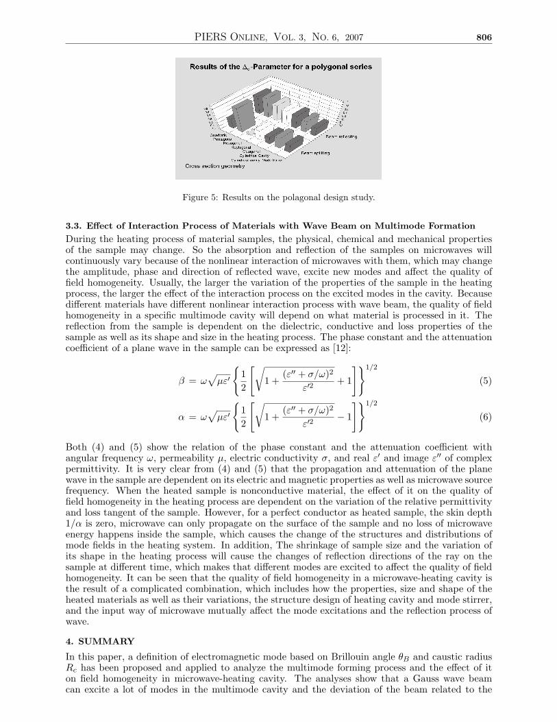
Figure 5 shows the numerical simulation results on the field quality of polygonal applicator designstudy for a) beam hitting the bare surface and b) beam hitting an edge based on MiRa code. Itcan be seen that, if the beam is hitting the wall of the applicator at the first reflection, the bestquality of field homogeneity can be reached for the applicator configuration of “circular cylindricalgeometry +stirrer”. However, if the beam is hitting an edge of a polygonal applicator at the firstreflection, except pentagonal applicator, the qualities of field homogeneity are all better than thoseof that beam hits the wall of the applicators at the first reflection. A significant minimum for ∆d
can be detected for a hexagonal shape. The experimental results performed at ForschungszentrumKarlsruhe are in good agreement with the simulations based on MiRa code [11].
PIERS ONLINE, VOL. 3, NO. 6, 2007 806
Figure 5: Results on the polagonal design study.
3.3. Effect of Interaction Process of Materials with Wave Beam on Multimode FormationDuring the heating process of material samples, the physical, chemical and mechanical propertiesof the sample may change. So the absorption and reflection of the samples on microwaves willcontinuously vary because of the nonlinear interaction of microwaves with them, which may changethe amplitude, phase and direction of reflected wave, excite new modes and affect the quality offield homogeneity. Usually, the larger the variation of the properties of the sample in the heatingprocess, the larger the effect of the interaction process on the excited modes in the cavity. Becausedifferent materials have different nonlinear interaction process with wave beam, the quality of fieldhomogeneity in a specific multimode cavity will depend on what material is processed in it. Thereflection from the sample is dependent on the dielectric, conductive and loss properties of thesample as well as its shape and size in the heating process. The phase constant and the attenuationcoefficient of a plane wave in the sample can be expressed as [12]:
β = ω√
µε′{
12
[√1 +
(ε′′ + σ/ω)2
ε′2+ 1
]}1/2
(5)
α = ω√
µε′{
12
[√1 +
(ε′′ + σ/ω)2
ε′2− 1
]}1/2
(6)
Both (4) and (5) show the relation of the phase constant and the attenuation coefficient withangular frequency ω, permeability µ, electric conductivity σ, and real ε′ and image ε′′ of complexpermittivity. It is very clear from (4) and (5) that the propagation and attenuation of the planewave in the sample are dependent on its electric and magnetic properties as well as microwave sourcefrequency. When the heated sample is nonconductive material, the effect of it on the quality offield homogeneity in the heating process are dependent on the variation of the relative permittivityand loss tangent of the sample. However, for a perfect conductor as heated sample, the skin depth1/α is zero, microwave can only propagate on the surface of the sample and no loss of microwaveenergy happens inside the sample, which causes the change of the structures and distributions ofmode fields in the heating system. In addition, The shrinkage of sample size and the variation ofits shape in the heating process will cause the changes of reflection directions of the ray on thesample at different time, which makes that different modes are excited to affect the quality of fieldhomogeneity. It can be seen that the quality of field homogeneity in a microwave-heating cavity isthe result of a complicated combination, which includes how the properties, size and shape of theheated materials as well as their variations, the structure design of heating cavity and mode stirrer,and the input way of microwave mutually affect the mode excitations and the reflection process ofwave.
4. SUMMARY
In this paper, a definition of electromagnetic mode based on Brillouin angle θB and caustic radiusRc has been proposed and applied to analyze the multimode forming process and the effect of iton field homogeneity in microwave-heating cavity. The analyses show that a Gauss wave beamcan excite a lot of modes in the multimode cavity and the deviation of the beam related to the
PIERS ONLINE, VOL. 3, NO. 6, 2007 807
cavity axis can alleviate the field concentrations in center, but microwave energy may only be storedin few modes. Mode-stirring technology can well solve the problem through designing the shape,direction, rotating way and periodical motion of the stirrer to change propagation direction andincrease reflection times of the rays for exciting more modes and causing time-averaged homogeneityof field in the cavity. However, there exists difficulty to design the shape and rotating way of themode stirrer for changing the modes to higher order modes than those formed by the wave beamat the first reflection, which may cause field concentration in center. Changing the configurationof the cavity from circular cylindrical surface to polygonal cylindrical one can enlarge the inputangle of the ray when the wave beam is input by hitting an edge of the polygonal applicator,which provides an opportunity to excite higher order modes for alleviating field concentration incenter. The simulations with MiRa code developed at FZK have shown that the best quality offield homogeneity can be reached for a hexagonal shape cavity, which is in good agreement withexperimental results. In addition, the multimode formation is also affected by the properties,size and shape of the heated materials as well as their variations in the heating process. Thehomogeneity of field and temperature distributions is determined by combination of the propertiesand structure of the heated materials as well as their variations, the structure design of heatingcavity and mode stirrer, with the input way of microwave.
ACKNOWLEDGMENT
Author would like to acknowledge Prof. M. Thumm, Dr. L. Feher and G. Link for helpful discussionand simulation results.
REFERENCES
1. Schiffmann, R. F., Microwave: Theory and Application in Material processing III (CeramicTransactions 59), D. Clark et al. (Westerville, OH: The American Ceramic Society), 7–16,1995.
2. Bykov, Y. V., et al., “High-temperature microwave processing of materials,” J. Phys. D: Appl:Phys., Vol. 34, R55-R75, 2001.
3. Clark, D. E., et al., “Microwave processing of materials,” Annu. Rev. Mater. Sci., Vol. 26,299–331, 1996.
4. Zhang, S.-L, et al., “Rapid thermal processing with microwave heating,” Thin Solid Film,Vol. 246, 151–157, 1994.
5. Roy, R., et al., “Microwave processing: triumph of applications-driven science in WC-composites and ferric tianates,” Cera, Trans., Vol. 80, 3–26, 1997.
6. Cherradi, G., et al., “Electric and magnetic field contribution to the microwave sintering ofceramics,” Electrocramics IV, (eds. Wasner, R. et al), Vol. 2, 1219–1224, RWTN, Aachen,1994.
7. Roy, R., et al., “Full sintering of powder-metal bodies in a microwave field,” Nature, Vol. 399,668, June 17, 1999.
8. Patterson, et al., WO92/1343, PCT9. Thumm, M. K., et al., “Passive high-power microwave components,” IEEE Trans. on Plasma
Science, Vol. 30, 755, June 2002.10. Weinstein, L. A., Open Oscillators and Open Waveguides, Golem, Press, Boulder, Colorado,
1969.11. Feher, L., G. Link, and M. Thumm, “Optimized design of an industrial millimeter wave ap-
plicator for homogeneous processing of ceramic charges”, Proc. Conf. Microwave and HighFrequency Heating 1997, A. Breccia, R. De Leo, and A. C. Metaxas, Eds., 442–446, Bologna,Italy, 1997.
12. Zhang, K. and D. Li, “Electromagnetic theory for microwaves and optoelectronics,” Springer-Verlag Berlin Heidelberg, 1998.