
An Investigation on M-Polar Fuzzy Saturation Graph and Its ...

International Research Journal of Engineering and Technology (IRJET) e-ISSN: 2395-0056
Volume: 02 Issue: 08 | Nov-2015 www.irjet.net p-ISSN: 2395-0072
© 2015, IRJET ISO 9001:2008 Certified Journal Page 693
Adaptive fuzzy & Neuro-Fuzzy Inference controller based MPPT for
photovoltaic systems
M.Balaji Naik1, Dr.P.Sujatha2
1PG Scholar, Department of EEE,JNTU Anantapur, Andhra Pradesh, India
Professor in EEE Dept., JNTUCEA, Anantapur
---------------------------------------------------------------------***----------------------------------------------------------------------Abstract: This paper grants a smart technique called Adaptive Neuro Fuzzy Inference controller (ANFIS) to optimize the performances of photovoltaic techniques. The method consists of a PV panel, a DC–DC booster converter, a maximum power point tracker controller and a resistive load. ANFIS methodology comprises of a hybrid system of fuzzy logic and neural network technique. The fuzzy logic takes into account the decision making based on the rules and uncertainty of the system that is being modeled while the neural network gives it a sense of adaptability. The important thing of the proposed strategy is the use of a ANFIS controller is trained to generate maximum power corresponding to the given solar irradiance level and temperature. The performances of the ANFIS are compared with those obtained using a conventional Adaptive fuzzy controllers with different gains and in each case, the proposed ANFIS controller outperforms its conventional counterpart.
Keywords:PV panel, ANFIS, Output scaling factor,
Fuzzy rules.
1. INTRODUCTION
The ever-increasing utilization of energy, fossil fuels soaring costs and exhaustible nature, and worsening global environment have created a booming interest in renewable energy generation systems, one of which is photovoltaic. Such a system generates electricity by converting the Sun’s energy directly into electricity. The Conventional sources of energy are rapidly decreasing. Moreover the cost of energy is increasing and therefore photovoltaic system is a promising alternative. They are scarce, pollution free, distributed throughout the earth and recyclable. The hindrance factor is it’s high installation cost and low conversion efficiency. Therefore our aim is to increase the efficiency and power output of the system. It is also required that constant voltage be supplied to the load irrespective of the variation in solar irradiance and temperature. PV arrays consist of parallel and series combination of PV cells that are used to generate electrical power depending upon the atmospheric
conditions (e. g solar irradiation and temperature). So it is necessary to couple the PV array with a boost converter. More over our system is designed in such a way that with variation in load, the change in input voltage and power fed into the converter follows the open circuit characteristics of the PV array. Our system can be used to supply constant stepped up voltage to the fuzzy logic controller to convert the given dc input to the respective ac output.The photovoltaic renewable energy generation is attracting a growing amount of political and commercial interest. The growth of photovoltaic (PV) systems has exceeded the most optimistic estimations because of the many merits they have such as providing a green renewable power by exploiting solar energy, autonomous operation without any noise generation. In addition their easy use make them suitable to both home energy applications and small-scale power generation applications.
Several methods have been proposed in the
literature for tracking the MPP of PV systems. Among
these methods, Hill climbing perturb and observe (P and
O) algorithms were commonly used due to their straight
forward and low cost implementation. An alternative
approach that overcomes this effect is called the
increment inductance method. However, all these listed
methods did not respond correctly under rapidly
changing atmospheric conditions. Recently MPPT
methods based on artificial intelligence techniques such
as neural networks, genetic algorithmsand fuzzy
controllers have emerged. The use of Adaptive neuro
fuzzy inference controller (ANFIS) is more suitable for
MPPT compared with conventional controllers because
they produce a better performance with changing
atmospheric conditions
In this paper, an ANFS controller is used to track
the MPP of a photovoltaic panel. The proposed fuzzy
Inference controller is significantly different from others
as it uses an adaptive output scaling factor which can
provide a good performance for PV systems. The rest of
the paper is organized in four sections. In Section 2, the
mathematical model of the PV module is presented. The
International Research Journal of Engineering and Technology (IRJET) e-ISSN: 2395-0056
Volume: 02 Issue: 08 | Nov-2015 www.irjet.net p-ISSN: 2395-0072
© 2015, IRJET ISO 9001:2008 Certified Journal Page 694
structure of the adaptive fuzzy inference controller is
described in detail in Section 3. Section 4 presents the
simulation results. Finally, a general conclusion is given
in Section 5.
2. Photovoltaic panel modelization
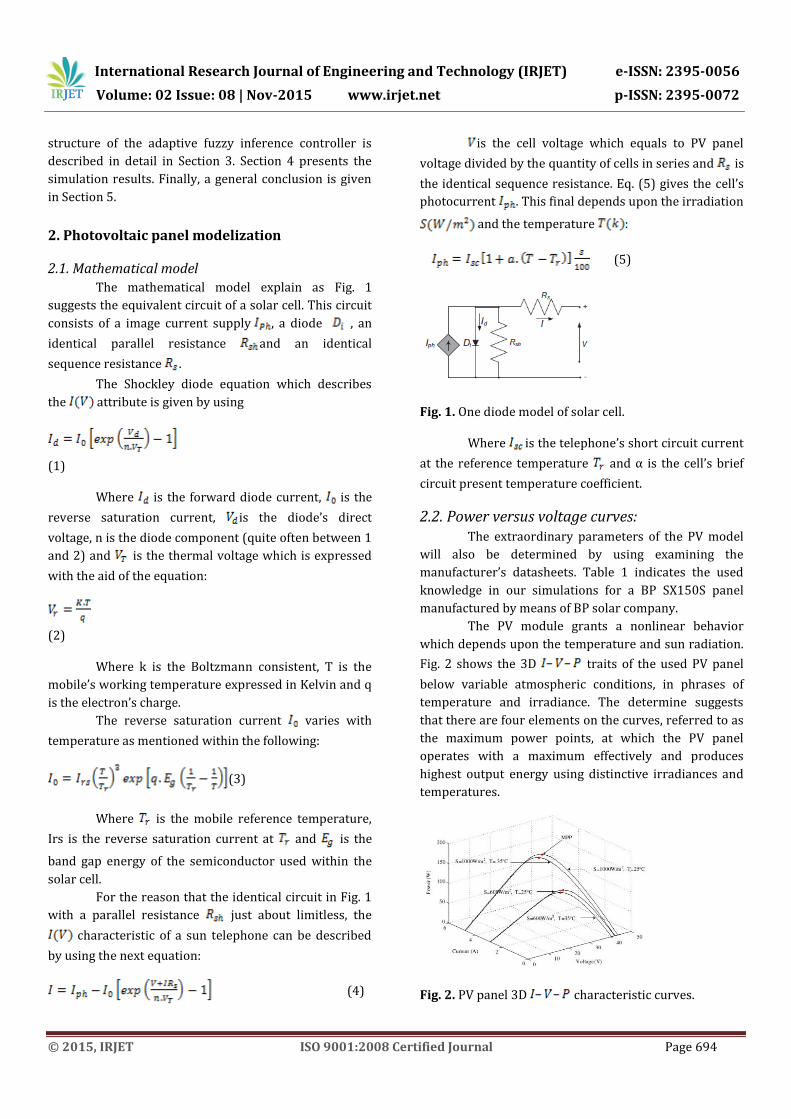
2.1. Mathematical model The mathematical model explain as Fig. 1
suggests the equivalent circuit of a solar cell. This circuit
consists of a image current supply , a diode , an
identical parallel resistance and an identical
sequence resistance .
The Shockley diode equation which describes
the attribute is given by using
(1)
Where is the forward diode current, is the
reverse saturation current, is the diode’s direct
voltage, n is the diode component (quite often between 1
and 2) and is the thermal voltage which is expressed
with the aid of the equation:
(2)
Where k is the Boltzmann consistent, T is the
mobile’s working temperature expressed in Kelvin and q
is the electron’s charge.
The reverse saturation current varies with
temperature as mentioned within the following:
(3)
Where is the mobile reference temperature,
Irs is the reverse saturation current at and is the
band gap energy of the semiconductor used within the
solar cell.
For the reason that the identical circuit in Fig. 1
with a parallel resistance just about limitless, the
characteristic of a sun telephone can be described
by using the next equation:
(4)
is the cell voltage which equals to PV panel
voltage divided by the quantity of cells in series and is
the identical sequence resistance. Eq. (5) gives the cell’s
photocurrent . This final depends upon the irradiation
and the temperature :
(5)
Fig. 1. One diode model of solar cell.
Where is the telephone’s short circuit current
at the reference temperature and α is the cell’s brief
circuit present temperature coefficient.
2.2. Power versus voltage curves: The extraordinary parameters of the PV model
will also be determined by using examining the
manufacturer’s datasheets. Table 1 indicates the used
knowledge in our simulations for a BP SX150S panel
manufactured by means of BP solar company.
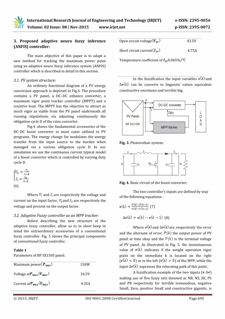
The PV module grants a nonlinear behavior
which depends upon the temperature and sun radiation.
Fig. 2 shows the 3D traits of the used PV panel
below variable atmospheric conditions, in phrases of
temperature and irradiance. The determine suggests
that there are four elements on the curves, referred to as
the maximum power points, at which the PV panel
operates with a maximum effectively and produces
highest output energy using distinctive irradiances and
temperatures.
Fig. 2. PV panel 3D characteristic curves.
International Research Journal of Engineering and Technology (IRJET) e-ISSN: 2395-0056
Volume: 02 Issue: 08 | Nov-2015 www.irjet.net p-ISSN: 2395-0072
© 2015, IRJET ISO 9001:2008 Certified Journal Page 695
3. Proposed adaptive neuro fuzzy inference
(ANFIS) controller:
The main objective of this paper is to adapt a
new method for tracking the maximum power point
using an adaptive neuro fuzzy inference system (ANFIS)
controller which is described in detail in this section.
3.1. PV system structure: An ordinary functional diagram of a PV energy
conversion approach is depicted in Fig.3. The procedure
contains a PV panel, a DC–DC enhance converter, a
maximum vigor point tracker controller (MPPT) and a
resistive load. The MPPT has the objective to attract as
much vigor as viable from the PV panel underneath all
running stipulations via adjusting continuously the
obligation cycle D of the raise converter.
Fig.4. shows the fundamental accessories of the
DC–DC boost converter in most cases utilized in PV
programs. The energy change Sw modulates the energy
transfer from the input source to the burden when
managed via a various obligation cycle D. In our
simulation we use the continuous current typical model
of a boost converter which is controlled by varying duty
cycle D.
(6)
Where and are respectively the voltage and
current on the input factor, and are respectively the
voltage and present on the output factor.
3.2. Adaptive Fuzzy controller as an MPP tracker:
Before describing the new structure of the
adaptive fuzzy controller, allow us to in short keep in
mind the extraordinary accessories of a conventional
fuzzy controller. Fig. 5 shows the principal components
of conventional fuzzy controller.
Table 1
Parameters of BP SX150S panel.
Maximum power 150W
Voltage at 34.5V
Current at 4.35A
Open circuit voltage 43.5V
Short circuit current 4.75A
Temperature coefficient of 0.065%/
In the fuzzification the input variables and
can be converts to linguistic values equivalent
constructive enormous and terrible big.
Fig. 3. Photovoltaic system.
Fig. 4. Basic circuit of the boost converter.
The two controller’s inputs are defined by way
of the following equations:
(7)
(8)
Where and are respectively the error
and the alternate of error, the output power of PV
panel at time okay and the is the terminal voltage
of PV panel. As illustrated in Fig. 5, the instantaneous
value of indicates if the weight operation vigor
point on the immediate k is located on the right
( ) or in the left ( ) of the MPP, while the
input expresses the relocating path of this point.
A fuzzification example of the two inputs ( )
making use of five fuzzy sets denoted as NB, NS, ZE, PS
and PB respectively for terrible tremendous, negative
Small, Zero, positive Small and constructive gigantic, is
International Research Journal of Engineering and Technology (IRJET) e-ISSN: 2395-0056
Volume: 02 Issue: 08 | Nov-2015 www.irjet.net p-ISSN: 2395-0072
© 2015, IRJET ISO 9001:2008 Certified Journal Page 696
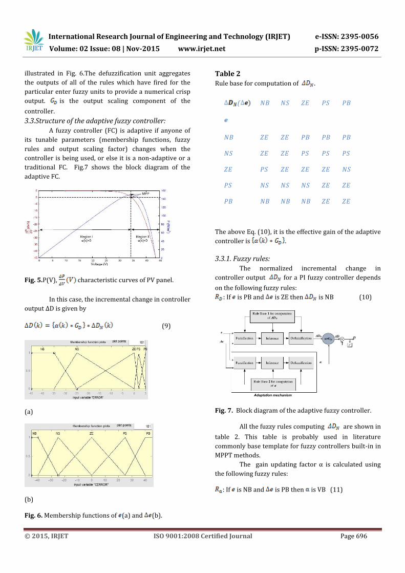
illustrated in Fig. 6.The defuzzification unit aggregates
the outputs of all of the rules which have fired for the
particular enter fuzzy units to provide a numerical crisp
output. is the output scaling component of the
controller.
3.3.Structure of the adaptive fuzzy controller:
A fuzzy controller (FC) is adaptive if anyone of
its tunable parameters (membership functions, fuzzy
rules and output scaling factor) changes when the
controller is being used, or else it is a non-adaptive or a
traditional FC. Fig.7 shows the block diagram of the
adaptive FC.
Fig. 5.P(V), characteristic curves of PV panel.
In this case, the incremental change in controller
output ΔD is given by
(9)
(a)
(b)
Fig. 6. Membership functions of (a) and (b).
Table 2 Rule base for computation of .
The above Eq. (10), it is the effective gain of the adaptive
controller is .
3.3.1. Fuzzy rules:
The normalized incremental change in
controller output for a PI fuzzy controller depends
on the following fuzzy rules:
: If is PB and is ZE then is NB (10)
Fig. 7. Block diagram of the adaptive fuzzy controller.
All the fuzzy rules computing are shown in
table 2. This table is probably used in literature
commonly base template for fuzzy controllers built-in in
MPPT methods.
The gain updating factor α is calculated using
the following fuzzy rules:
: If is NB and is PB then is VB (11)
( NB NS ZE PS PB
NB ZE ZE PB PB PB
NS ZE ZE PS PS PS
ZE PS ZE ZE ZE NS
PS NS NS NS ZE ZE
PB NB NB NB ZE ZE

International Research Journal of Engineering and Technology (IRJET) e-ISSN: 2395-0056
Volume: 02 Issue: 08 | Nov-2015 www.irjet.net p-ISSN: 2395-0072
© 2015, IRJET ISO 9001:2008 Certified Journal Page 697
Table 3 Rule base for computation of α
I
n
this
pape
r, to
achie
ve
atrac
king
of
the
MPP, the rule base depicted in desk three is designed
and used to calculate the gain updating factor α.
Fig. 8. Membership functions of .
Fig. 9. Membership functions of α.
3.3.2. Membership Functions of the Controller’s
Variables
The membership functions of the two input
variables error and change of error are defined
respectively on the intervals and
. The limits of these intervals are
determined based on the characteristic curves of the
studied PV system and are fine tuned through trial and
error to achieve good performances. For example, in Fig
5 , it is clear that the variable error takes
its possible values in the interval . Therefore, it
is logic to define all the associated membership functions
in the interval as it is illustrated in Fig 6(a).
Unlike the input variables, the membership
functions of the control’s normalized output and the
gain updating factor α are defined independently from
the PV panel characteristics. is normalized on interval
and is normalized on interval . Their
respective associated membership functions are shown
in Fig 8 and 9 respectively.
3.4. Structure of ANFS controller:
If ) is taken to be a first order
polynomial a first order Sugeno fuzzy model is formed.
For a first order two rule Sugeno fuzzy inference system,
the two rules may be stated as:
: If is NB and is PB then
: If is NB and is PS then
Here type-3 fuzzy inference system proposed by
Takagi and Sugeno is used. In this inference system the
output of each rule is a linear
Fig. 10. ANFIS Structure.
combination of the input variables added by a constant
term. The final output is the weighted average of each
rule’s output. The corresponding equivalent ANFIS
structure is shown in Fig. 10.
The individual layers of this ANFIS structure are
described below :
Layer 1: Every node iin this layer is adaptive with a node
function
(12)
( NB NS ZE PS PB
NB ZE ZE MB B VB
NS ZE ZE VB VS SB
ZE S ZE ZE ZE S
PS S SB VS ZE ZE
PB VB VS SB ZE ZE

International Research Journal of Engineering and Technology (IRJET) e-ISSN: 2395-0056
Volume: 02 Issue: 08 | Nov-2015 www.irjet.net p-ISSN: 2395-0072
© 2015, IRJET ISO 9001:2008 Certified Journal Page 698
where, is the input to node , is the linguistic
variable associated with this node function and is the
membership function of . Usually is chosen as
(13)
where is the input and is the premise
parameter set.
Layer 2: Each node in this layer is a fixed node which
calculates the firing strength of a rule. The output of
each node is the product of all the incoming signals to it
and is given by,
(14)
Layer 3: Every node in this layer is a fixed node. Each
node calculates the ratio of the rule’s firing strength
to the sum of firing strengths of all the rules. The output
from the node is thenormalized firing strength given
by,
(15)
Layer 4: Every node in this layer is an adaptive node with
a node function given by
(16)
Where is the output of Layer 3 and is
the consequent parameter set.
Layer 5: This layer comprises of only one fixed node that
calculates the overall output as the summation of all
incoming signals, i.e.
(17)
3.5.Learning Algorithm of ANFS controller:
In the ANFIS structure, it is observed that given
the values of premise parameters, the final output can be
expressed as a linear combination of the consequent
parameters. The output f in Fig. 10 can be written as
(18) where is linear in the consequent parameters
( .
Table 4
Rules for ANFIS:
D
NE NE NE
NE NE ZE
NE PS PS
NE NE NE
ZE NE ZE
ZE PS PS
PS NE NE
PS ZE ZE
PS PS PS
In the forward pass of the learning algorithm,
consequent parameters are identified by the least
squaresestimate. In the backward pass, the error signals,
which are the derivatives of the squared error with
respect to each node output, propagate backward from
the output layer to the input layer. In this backward pass,
the premise parameters are updated by the gradient
descent algorithm
International Research Journal of Engineering and Technology (IRJET) e-ISSN: 2395-0056
Volume: 02 Issue: 08 | Nov-2015 www.irjet.net p-ISSN: 2395-0072
© 2015, IRJET ISO 9001:2008 Certified Journal Page 699
3.6. Optimization of the initial fuzzy model
The ANFIS structure of the system which is
being modeled is considered as the final model for which
the RMSE is the minimum. The consequent parameters
of the initial fuzzy model are updated by using the Least
squares estimation (LSE) algorithm.
Similarly, the rules which are obtained from the
clustering or the grid partition based method are
updated by neural network which uses back propagation
learning method with gradient descent algorithm. This
updation leads to the optimization of the premise
parameters of the fuzzy membership functions to give
the final fuzzy model
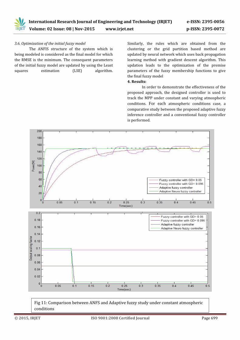
4. Results:
In order to demonstrate the effectiveness of the
proposed approach, the designed controller is used to
track the MPP under constant and varying atmospheric
conditions. For each atmospheric conditions case, a
comparative study between the proposed adaptive fuzzy
inference controller and a conventional fuzzy controller
is performed.
.
Fig 11: Comparison between ANFS and Adaptive fuzzy study under constant atmospheric
conditions
International Research Journal of Engineering and Technology (IRJET) e-ISSN: 2395-0056
Volume: 02 Issue: 08 | Nov-2015 www.irjet.net p-ISSN: 2395-0072
© 2015, IRJET ISO 9001:2008 Certified Journal Page 700
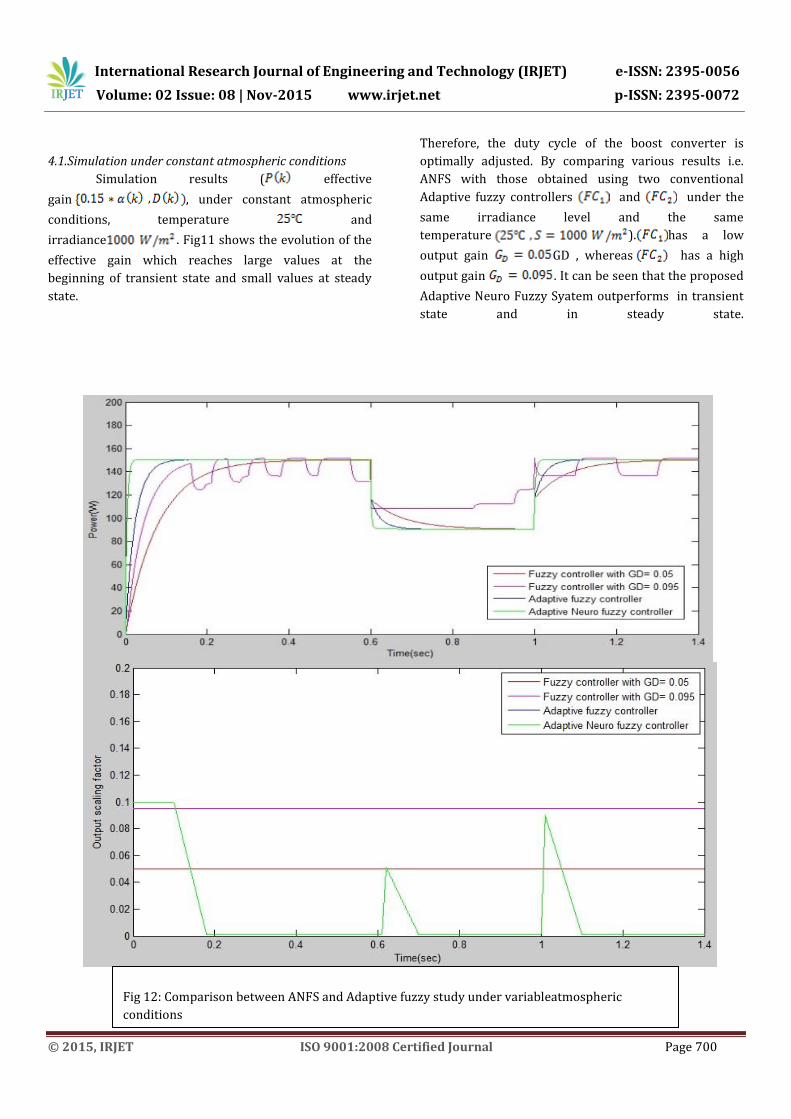
4.1.Simulation under constant atmospheric conditions
Simulation results ( effective
gain , under constant atmospheric
conditions, temperature and
irradiance . Fig11 shows the evolution of the
effective gain which reaches large values at the
beginning of transient state and small values at steady
state.
Therefore, the duty cycle of the boost converter is
optimally adjusted. By comparing various results i.e.
ANFS with those obtained using two conventional
Adaptive fuzzy controllers and under the
same irradiance level and the same
temperature ). has a low
output gain GD , whereas has a high
output gain . It can be seen that the proposed
Adaptive Neuro Fuzzy Syatem outperforms in transient
state and in steady state.
Fig 12: Comparison between ANFS and Adaptive fuzzy study under variableatmospheric
conditions

International Research Journal of Engineering and Technology (IRJET) e-ISSN: 2395-0056
Volume: 02 Issue: 08 | Nov-2015 www.irjet.net p-ISSN: 2395-0072
© 2015, IRJET ISO 9001:2008 Certified Journal Page 701
4.2.Simulation under variable atmospheric conditions
In this part, by applying controller to the PV
system under the following conditions: constant
temperature and rapid changes in solar
radiation (a change from to
at t = 0.6 s and a change back to 1000 W/m2
at t = 1 s). The obtained results are presented in Figs. 12.
The effective gain output presents highly nonlinear
variations, especially at instants of change in irradiance
level
Conclusion
In this paper, an adaptive neuro fuzzy inference
controller is used to track the maximum power from the
PV arrays. This method is updated by neural network
which uses back propagation learning method with
gradient descent algorithm. Simulation results show that
the proposed controller can track the maximum power
point with higher performances when compared to its
adaptive fuzzy logic controller. For that reason the
introducing of an adaptive neuro fuzzy to fulfill the
requirement of needs of whole system.
References:
1] Xiao W, Dunford WG. A modified adaptive hill climbing
MPPT method for photovoltaic power systems. In: 35th
Annual IEEE Power Electronics, Specialists Conference,
Aachen, Germany; 2004. p. 1957–63.
[2] Femia N, Petrone G, Spagnuolo G, Vitelli M.
Optimization of perturb and observe maximum power
point tracking method. IEEE Trans Power Electron 2004;
20(4):16–9.
[3] Kuo YC, Liang TJ, Chen JF. Novel maximum power point
tracking controller for photovoltaic energy conversion
system. IEEE Trans Ind Electron 2001; 48(3):594–
601photovoltaic energy conversion system. IEEE Trans
Ind Electron 2001; 48(3):554-601.
[4] Liao CC. Genetic k-means Algorithm based RBF
network for photovoltaic MPP prediction. Energy 2010;35:
529-36.
[5] Hadji S, Krimand F, Gaubert JP. Development of an
algorithm of maximum power point tracking for
photovoltaic systems using genetic algorithms. In: 7th
International Workshop on Systems, Signal Processing and
their Applications (WOSSPA); 2011. p. 43–6.
[6] Boutalis YS, Karlis AD. New maximum power point
tracker for PV arrays using fuzzy controller in close
cooperation with fuzzy cognitive networks. IEEE Trans
Energy Convers 2006;21(3):793–803.
![On Fuzzy Weakly α-continuous Multifunctiondefined by chang [2], Fuzzy sets in to Y will be denoted λ, μ, ϑ & etc. And interior and closure fuzzy sets λ in an fts Y will be denoted](https://static.fdocument.org/doc/165x107/5e51f9b4d7c62048696146b2/on-fuzzy-weakly-continuous-multifunction-defined-by-chang-2-fuzzy-sets-in.jpg)