A SIMPLE CRYSTAL NOTCH CIRCUIT FOR NOISE MEASUREMENTS · NOTCH MEASUREMENTS 200 KHz Span +55...
12
A SIMPLE CRYSTAL NOTCH CIRCUIT FOR NOISE MEASUREMENTS Jacques Audet VE2AZX jacaudet [at] videotron [dot] ca I used Mini Circuits ZFSC-2-4 Broadband Combiner/Splitter OUT PORT IN PORT XTAL Tuner FROM: 50 Ω GENERATOR Under Test TO: 50 Ω SPECTRUM ANALYZER 12 MHz Crystal 5 Ω ESR Crystal Tuning Capacitor Adjust for best notch Adjust tuner for best notch ~100 Ω Controls Notch Width 200 Ω Combiner/splitter R Shielded MFJ Antenna Tuner L References: Oscillator Noise Evaluation with a crystal Notch Filter by Wes Hayward, W7ZOI QEX July/August 2008 HP RF & Microwave Phase Noise Measurement Seminar Select L to resonate above and below XTAL frequency.
Transcript of A SIMPLE CRYSTAL NOTCH CIRCUIT FOR NOISE MEASUREMENTS · NOTCH MEASUREMENTS 200 KHz Span +55...
A SIMPLE CRYSTAL NOTCH CIRCUIT FOR NOISE MEASUREMENTSJacques AudetVE2AZXjacaudet [at] videotron [dot] ca I used Mini Circuits
ZFSC-2-4 BroadbandCombiner/Splitter
OUT
PORT
IN
PORT
XTALTuner
FROM: 50 ΩGENERATORUnder Test
TO: 50 ΩSPECTRUMANALYZER
12 M
Hz
Cry
stal
5 Ω
ESR
Crystal Tuning CapacitorAdjust for best notch
Adjust tuner forbest notch
~100 ΩControlsNotchWidth
200 Ω
Combiner/splitter
R
Shielded
MFJ Antenna Tuner
L
References:Oscillator Noise Evaluation with a crystalNotch Filter by Wes Hayward, W7ZOIQEX July/August 2008
HP RF & Microwave Phase NoiseMeasurement Seminar
Select L to resonateabove and below XTALfrequency.
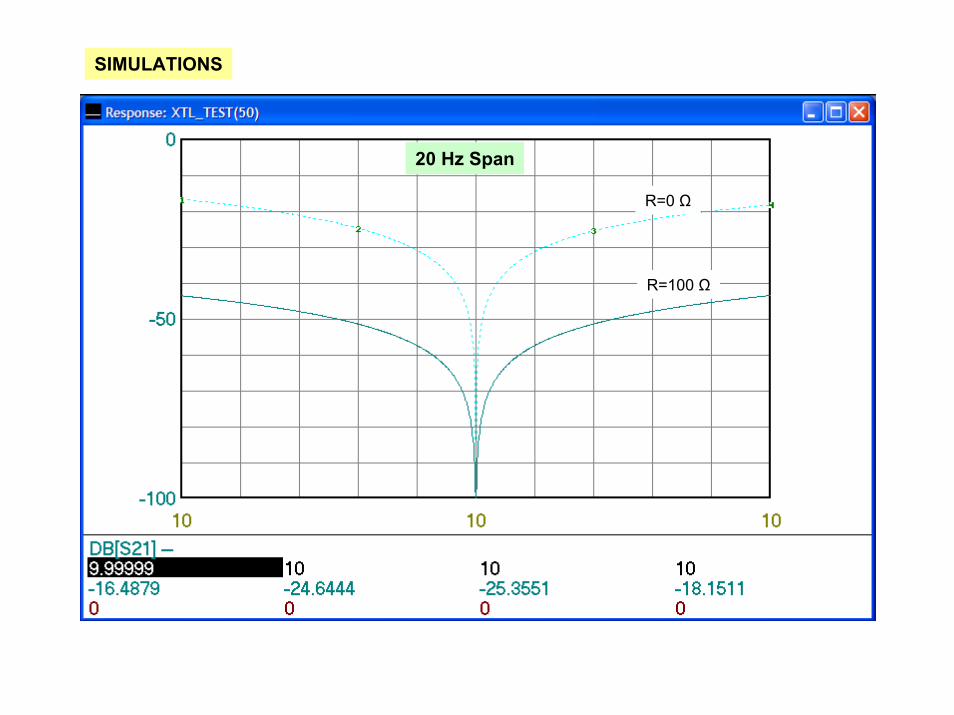
SIMULATIONS
20 Hz Span
R=0 Ω
R=100 Ω
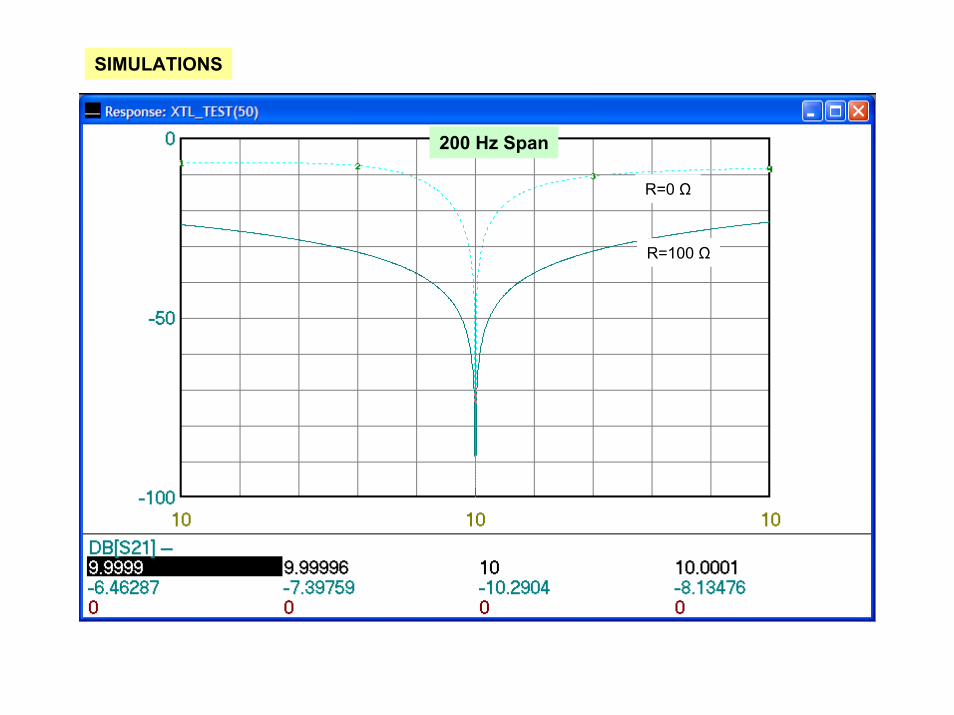
SIMULATIONS
200 Hz Span
R=0 Ω
R=100 Ω
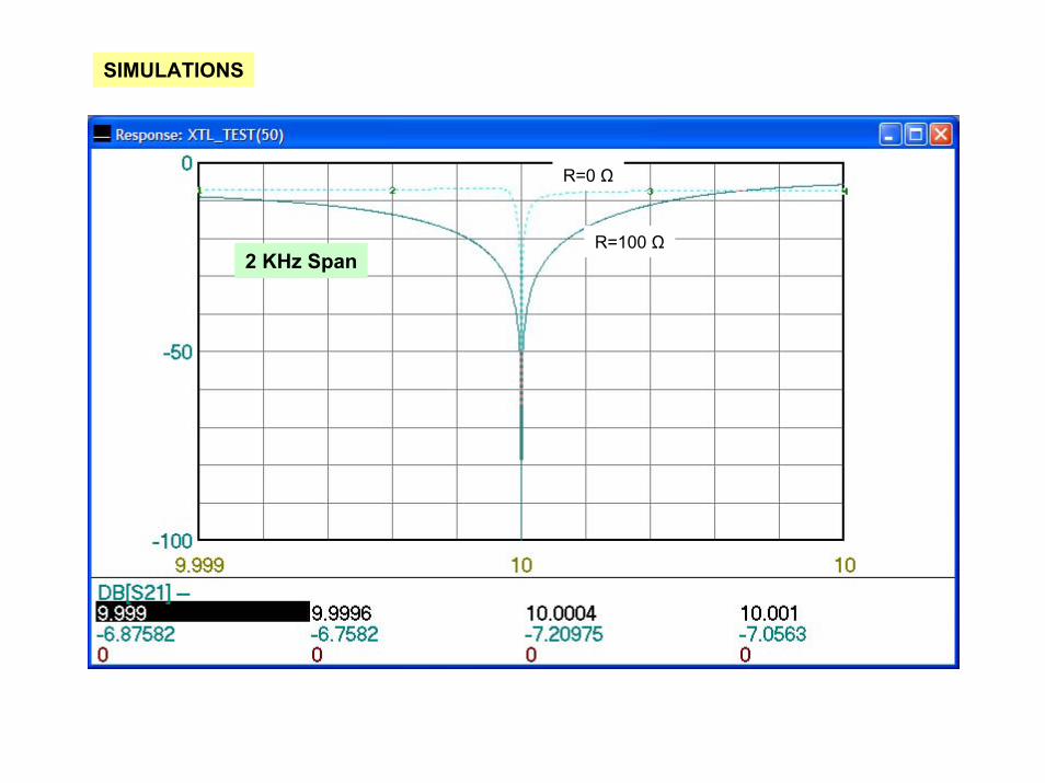
SIMULATIONS
2 KHz Span
R=0 Ω
R=100 Ω
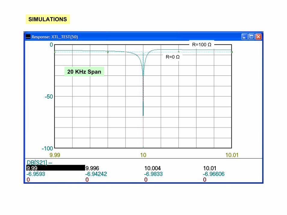
SIMULATIONS
20 KHz Span
R=0 Ω
R=100 Ω
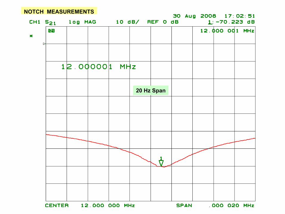
NOTCH MEASUREMENTS
20 Hz Span
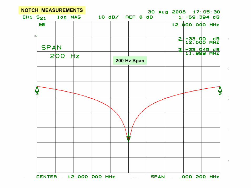
NOTCH MEASUREMENTS
200 Hz Span
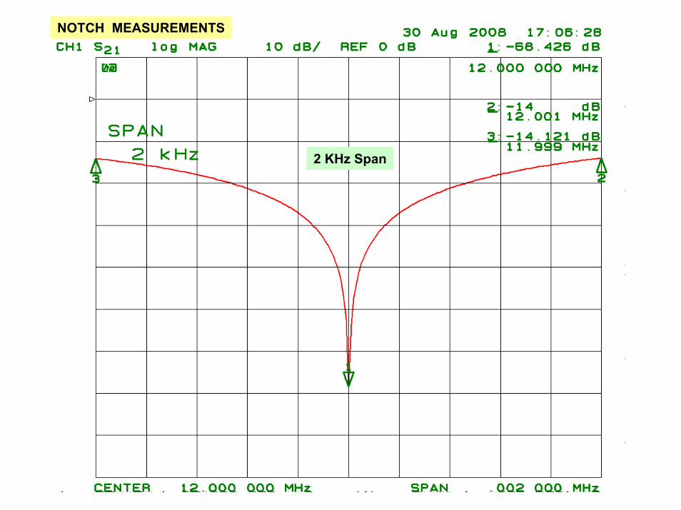
NOTCH MEASUREMENTS
2 KHz Span
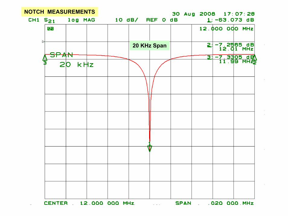
NOTCH MEASUREMENTS
20 KHz Span
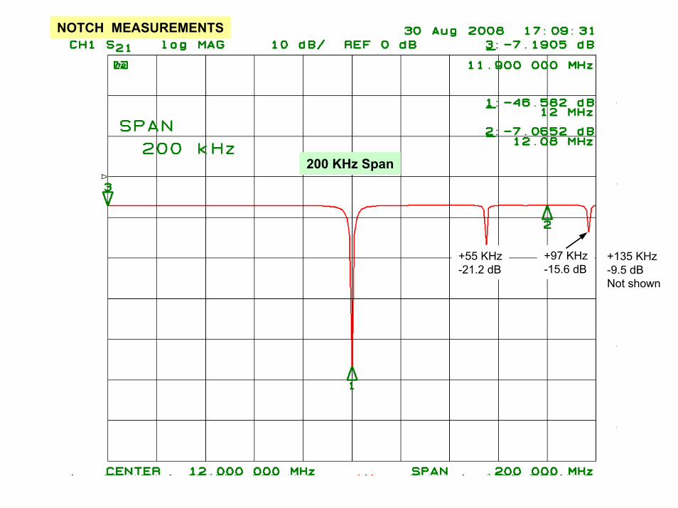
NOTCH MEASUREMENTS
200 KHz Span
+55 KHz-21.2 dB
+97 KHz-15.6 dB
+135 KHz-9.5 dBNot shown
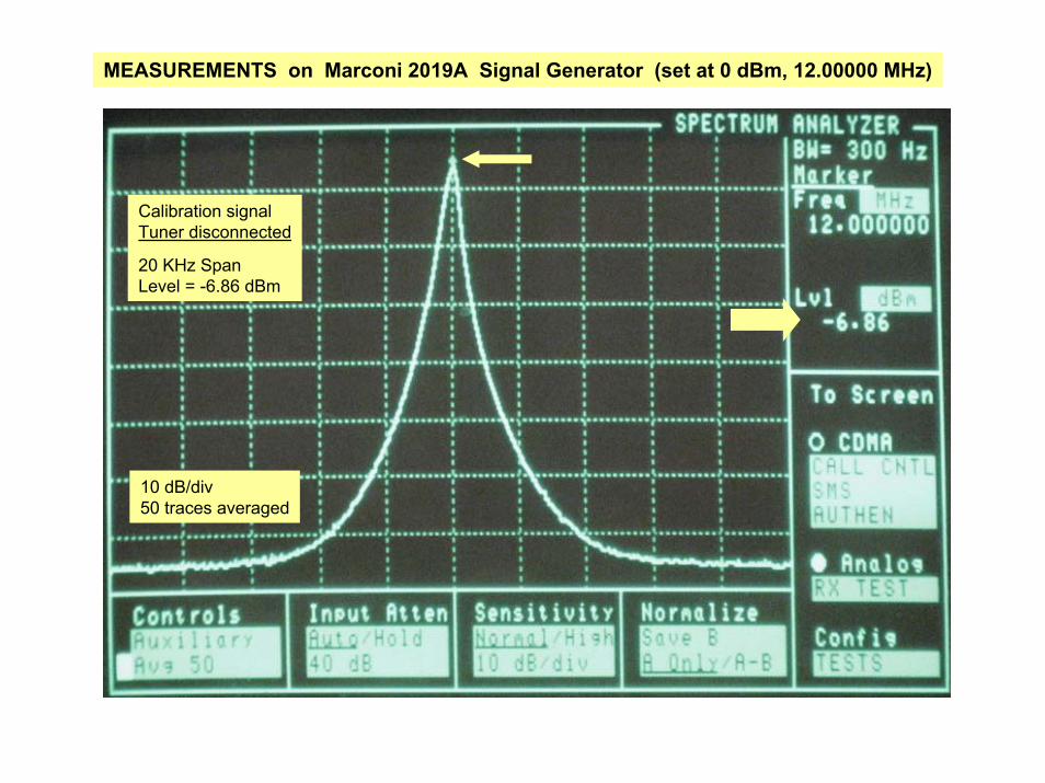
MEASUREMENTS on Marconi 2019A Signal Generator (set at 0 dBm, 12.00000 MHz)
Calibration signalTuner disconnected
20 KHz SpanLevel = -6.86 dBm
10 dB/div50 traces averaged
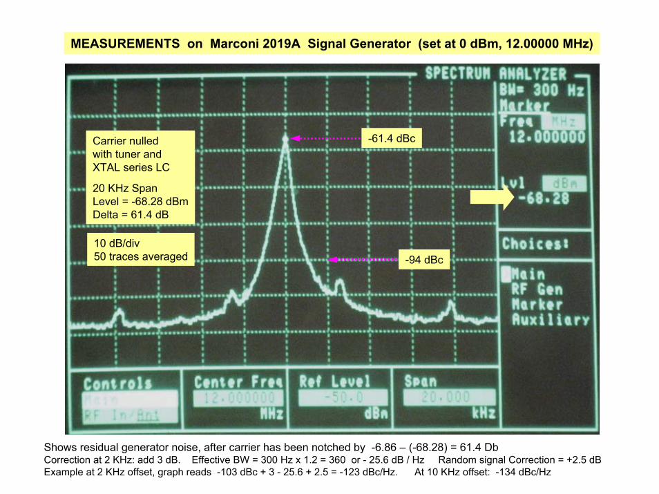
MEASUREMENTS on Marconi 2019A Signal Generator (set at 0 dBm, 12.00000 MHz)
Carrier nulledwith tuner andXTAL series LC
20 KHz SpanLevel = -68.28 dBmDelta = 61.4 dB
10 dB/div50 traces averaged -94 dBc
-61.4 dBc
Shows residual generator noise, after carrier has been notched by -6.86 – (-68.28) = 61.4 DbCorrection at 2 KHz: add 3 dB. Effective BW = 300 Hz x 1.2 = 360 or - 25.6 dB / Hz Random signal Correction = +2.5 dBExample at 2 KHz offset, graph reads -103 dBc + 3 - 25.6 + 2.5 = -123 dBc/Hz. At 10 KHz offset: -134 dBc/Hz