16.333 Lecture - MIT OpenCourseWare · Lateral Stability Derivatives ... – Influence of the roll...
13
16.333 Lecture # 8 Aircraft Lateral Dynamics Spiral, Roll, and Dutch Roll Modes
Transcript of 16.333 Lecture - MIT OpenCourseWare · Lateral Stability Derivatives ... – Influence of the roll...
16.333 Lecture # 8
Aircraft Lateral Dynamics
Spiral, Roll, and Dutch Roll Modes
� �
� �
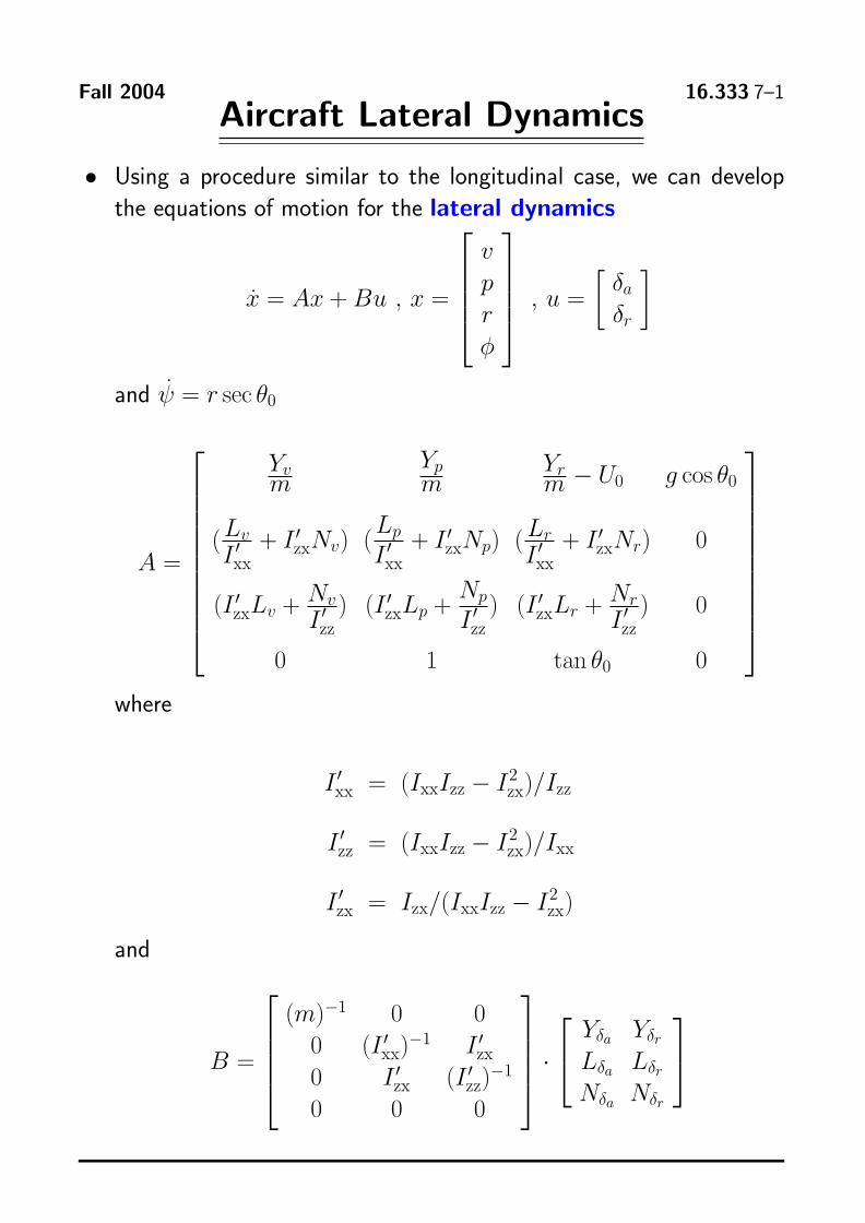
Fall 2004 16.333 7–1 Aircraft Lateral Dynamics
• Using a procedure similar to the longitudinal case, we can develop the equations of motion for the lateral dynamics ⎤⎡
v⎥⎥⎥⎦δa , u= δr
x = Ax + Bu , x =⎢⎢⎢⎣prφ
and ψ = r sec θ0
⎤⎡
A=
⎢⎢⎢⎢⎢⎢⎢⎢⎢⎣
Yv Yp Yr m− U0 g cos θ0m m
(IL�v + I � Nv) (
Lp + I � Np) ( Lr + I � Nr) 0zx zx I � zxI �xx xx xx
(I � Lv + Nv ) (I � Lp + Np ) (I � Lr + Nr ) 0zx I � zx zxI � I �zz zz zz
0 1 tan θ0 0
where
I � = (IxxIzz − I2 xx zx)/Izz
I � = (IxxIzz − I2 zz zx)/Ixx
I � = Izx/(IxxIzz − I2 zx zx)
and ⎤⎡ ⎢⎢⎢⎣
(m)−1 0 00 (I �xx)
−1 I �zx ⎥⎥⎥⎦
⎤⎡ Yδa Yδr
⎥⎥⎥⎥⎥⎥⎥⎥⎥⎦
⎣ ⎦B= Lδa Lδr zz)
−1 · zx (I0 I
Nδa Nδr0 0 0
� �
� �
Fall 2004 16.333 7–2
Lateral Stability Derivatives
• A key to understanding the lateral dynamics is rollyaw coupling.
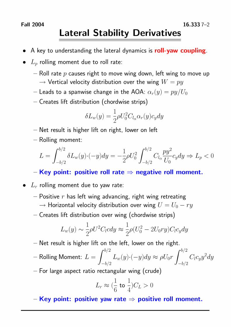
• Lp rolling moment due to roll rate:
– Roll rate p causes right to move wing down, left wing to move up → Vertical velocity distribution over the wing W = py
– Leads to a spanwise change in the AOA: αr(y) = py/U0
– Creates lift distribution (chordwise strips)
1 δLw(y) = ρU0
2Clα αr(y)cydy2 – Net result is higher lift on right, lower on left
– Rolling moment: b/2 b/2
L = δLw(y)·(−y)dy = −2
1 ρU0
2
−b/2 Clα
py2
cydy ⇒ Lp < 0 −b/2 U0
– Key point: positive roll rate ⇒ negative roll moment.
• Lr rolling moment due to yaw rate:
– Positive r has left wing advancing, right wing retreating → Horizontal velocity distribution over wing U = U0 − ry
– Creates lift distribution over wing (chordwise strips)
1 1 Lw(y) ∼ ρU 2Clcdy ≈ ρ(U0
2 − 2U0ry)Clcydy2 2
– Net result is higher lift on the left, lower on the right. b/2 b/2
– Rolling Moment: L = Lw(y)·(−y)dy ≈ ρU0r Clcyy 2dy −b/2 −b/2
– For large aspect ratio rectangular wing (crude)
1 1 Lr ≈ ( to )CL > 0
6 4
– Key point: positive yaw rate ⇒ positive roll moment.
Fall 2004 16.333 7–3
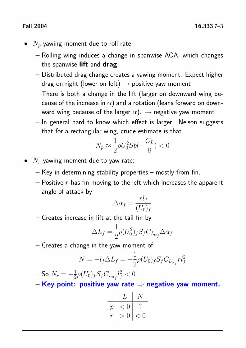
• Np yawing moment due to roll rate:
– Rolling wing induces a change in spanwise AOA, which changes the spanwise lift and drag.
– Distributed drag change creates a yawing moment. Expect higher drag on right (lower on left) → positive yaw moment
– There is both a change in the lift (larger on downward wing be
cause of the increase in α) and a rotation (leans forward on down
ward wing because of the larger α). → negative yaw moment
– In general hard to know which effect is larger. Nelson suggests that for a rectangular wing, crude estimate is that
1 Np ≈ ρU0
2Sb(− CL
) < 0 2 8
• Nr yawing moment due to yaw rate:
– Key in determining stability properties – mostly from fin.
– Positive r has fin moving to the left which increases the apparent angle of attack by
rlfΔαf =
(U0)f
– Creates increase in lift at the tail fin by 1
ΔLf = ρ(U02)fSfCLαf
Δαf2
– Creates a change in the yaw moment of 1
N = −lf ΔLf = −2 ρ(U0)fSfCLαf
rl2 f
1 – So Nr = 2 ρ(U0)fSfCLαf lf 2 < 0−
– Key point: positive yaw rate ⇒ negative yaw moment.
L N
p < 0 ? r > 0 < 0
Fall 2004 16.333 7–4
Numerical Results
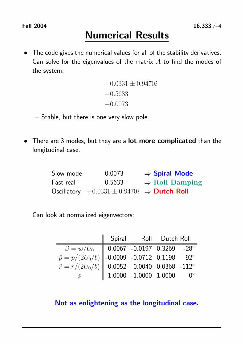
• The code gives the numerical values for all of the stability derivatives. Can solve for the eigenvalues of the matrix A to find the modes of the system.
−0.0331 ± 0.9470i
−0.5633
−0.0073
– Stable, but there is one very slow pole.
• There are 3 modes, but they are a lot more complicated than the longitudinal case.
Slow mode 0.0073 ⇒ Spiral Mode Fast real 0.5633 ⇒ Roll Damping Oscillatory −0.0331 ± 0.9470i Dutch Roll ⇒
Can look at normalized eigenvectors:
Spiral Roll Dutch Roll
β = w/U0 0.0067 0.0197 0.3269 28◦
p = p/(2U0/b) 0.0009 0.0712 0.1198 92◦
r = r/(2U0/b) 0.0052 0.0040 0.0368 112◦
φ 1.0000 1.0000 1.0000 0◦
Not as enlightening as the longitudinal case.
Fall 2004 16.333 7–5
Lateral Modes
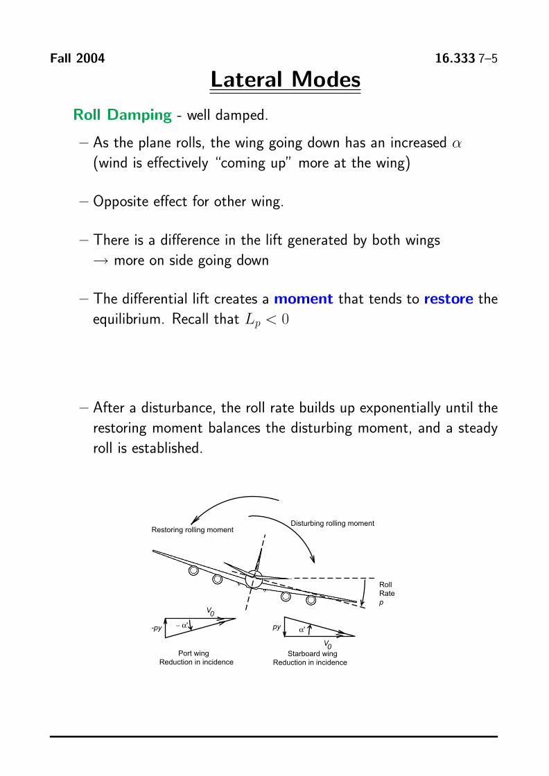
Roll Damping well damped.
– As the plane rolls, the wing going down has an increased α(wind is effectively “coming up” more at the wing)
– Opposite effect for other wing.
– There is a difference in the lift generated by both wings → more on side going down
– The differential lift creates a moment that tends to restore the equilibrium. Recall that Lp < 0
– After a disturbance, the roll rate builds up exponentially until the restoring moment balances the disturbing moment, and a steady roll is established.
py
V0
-py − �' �'
Roll Rate p
Disturbing rolling momentRestoring rolling moment
V0 Port wing Starboard wing
Reduction in incidence Reduction in incidence
Fall 2004 16.333 7–6
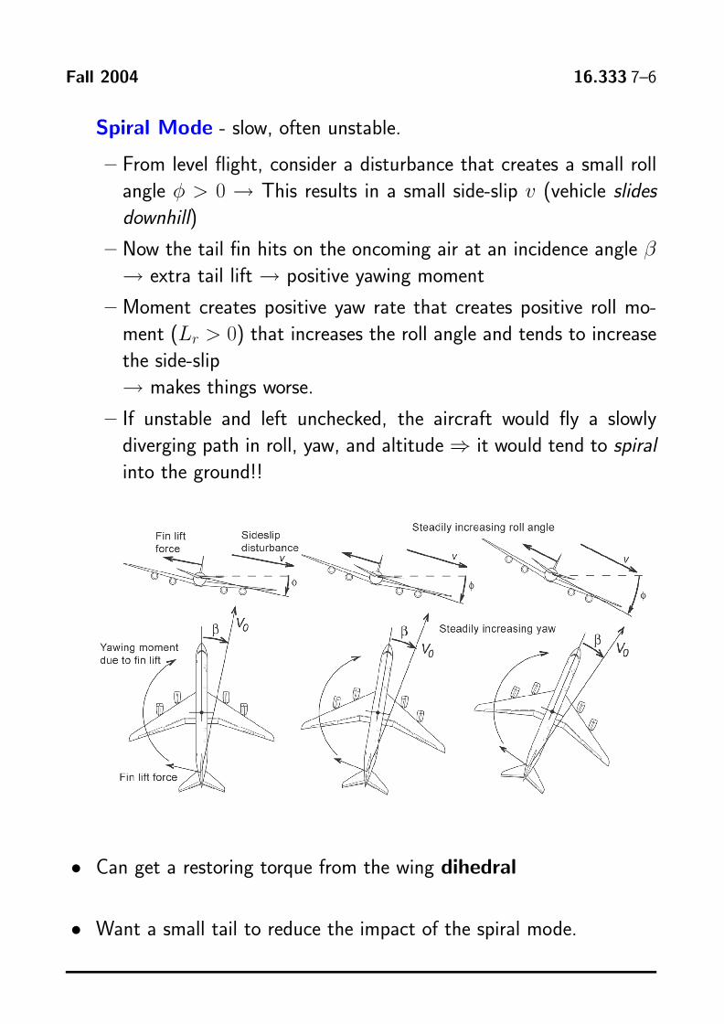
Spiral Mode slow, often unstable.
– From level flight, consider a disturbance that creates a small roll angle φ > 0 → This results in a small sideslip v (vehicle slides downhill)
– Now the tail fin hits on the oncoming air at an incidence angle β → extra tail lift → positive yawing moment
– Moment creates positive yaw rate that creates positive roll mo
ment (Lr > 0) that increases the roll angle and tends to increase the sideslip → makes things worse.
– If unstable and left unchecked, the aircraft would fly a slowly diverging path in roll, yaw, and altitude ⇒ it would tend to spiral into the ground!!
• Can get a restoring torque from the wing dihedral
• Want a small tail to reduce the impact of the spiral mode.
Fall 2004 16.333 7–7
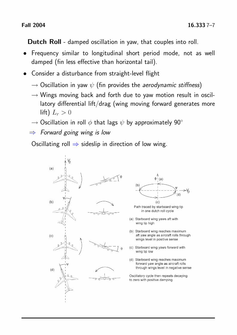
Dutch Roll damped oscillation in yaw, that couples into roll.
• Frequency similar to longitudinal short period mode, not as well damped (fin less effective than horizontal tail).
• Consider a disturbance from straightlevel flight
→Oscillation in yaw ψ (fin provides the aerodynamic stiffness)
→ Wings moving back and forth due to yaw motion result in oscil
latory differential lift/drag (wing moving forward generates more lift) Lr > 0
→Oscillation in roll φ that lags ψ by approximately 90◦
⇒ Forward going wing is low
Oscillating roll ⇒ sideslip in direction of low wing.
Fall 2004 16.333 7–8
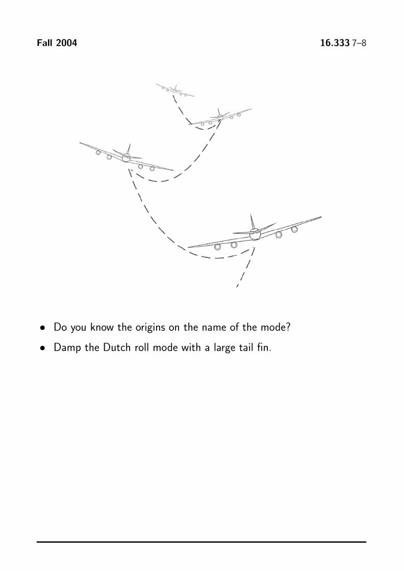
• Do you know the origins on the name of the mode?
• Damp the Dutch roll mode with a large tail fin.
Fall 2004 16.333 7–9
Aircraft Actuator Influence
10−2
10−1
100
10−2
10−1
100
101
102
|Gβda|
Freq
(rad
/sec
)10
−210
−110
010
−2
10−1
100
101
102
|Gpda|
Freq
(rad
/sec
)
Tran
sfer
func
tion
from
aile
ron
to fl
ight
var
iabl
es
10−2
10−1
100
10−2
10−1
100
101
102
|Grda|
Freq
(rad
/sec
)
10−2
10−1
100
−200
−150
−100−5
0050100
150
200
arg Gβda
Freq
(rad
/sec
)10
−210
−110
0
−350
−300
−250
−200
−150
−100−5
00
arg Gpda
Freq
(rad
/sec
)10
−210
−110
0−2
00
−150
−100−5
0050100
150
200
arg Grda
Freq
(rad
/sec
)
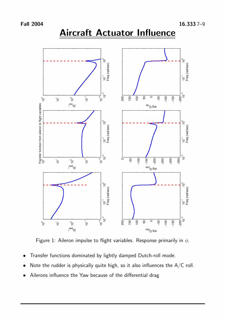
Figure 1: Aileron impulse to flight variables. Response primarily in φ.
• Transfer functions dominated by lightly damped Dutchroll mode.
• Note the rudder is physically quite high, so it also influences the A/C roll.
• Ailerons influence the Yaw because of the differential drag
Fall 2004 16.333 7–10
10−2
10−1
100
100
101
102
103
104
|Gβda|
Freq
(rad
/sec
)10
−210
−110
010
−2
10−1
100
101
102
|Gpda|
Freq
(rad
/sec
)
Tran
sfer
func
tion
from
rudd
er to
flig
ht v
aria
bles
10−2
10−1
100
10−2
10−1
100
101
102
|Grda|
Freq
(rad
/sec
)
10−2
10−1
100
−200
−150
−100−5
0050100
150
200
arg Gβda
Freq
(rad
/sec
)10
−210
−110
0
−500
−400
−300
−200
−1000
arg Gpda
Freq
(rad
/sec
)10
−210
−110
0
−300
−200
−1000
100
200
arg GrdaFr
eq (r
ad/s
ec)
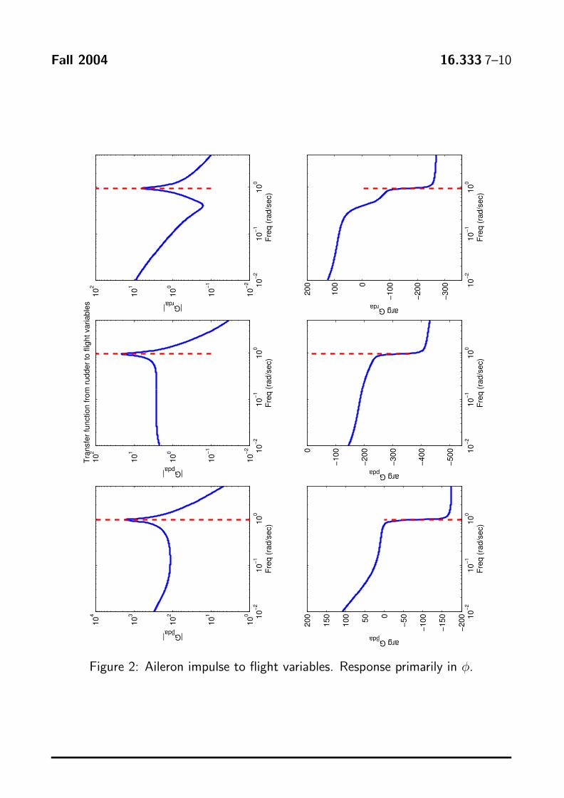
Figure 2: Aileron impulse to flight variables. Response primarily in φ.
Fall 2004 16.333 7–11
0 5 10 15 20 25 30−4
−2
0
2x 10⁻⁴
β ra
d
Aileron 1 deg Impulse − 2sec on then off
0 5 10 15 20 25 30−4
−2
0
2x 10⁻³
p ra
d/se
c δa > 0 ==> right wing up
0 5 10 15 20 25 30−5
0
5x 10⁻⁴
r rad
/sec
Initial adverse yaw ==> RY coupling
0 5 10 15 20 25 30−0.01
−0.005
0
φ ra
d
time sec
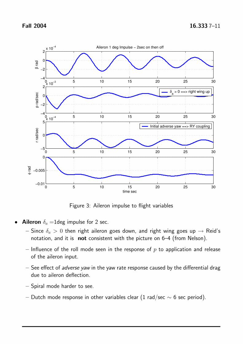
Figure 3: Aileron impulse to flight variables
• Aileron δa =1deg impulse for 2 sec.
– Since δa > 0 then right aileron goes down, and right wing goes up → Reid’s notation, and it is not consistent with the picture on 6–4 (from Nelson).
– Influence of the roll mode seen in the response of p to application and release of the aileron input.
– See effect of adverse yaw in the yaw rate response caused by the differential drag due to aileron deflection.
– Spiral mode harder to see.
– Dutch mode response in other variables clear (1 rad/sec ∼ 6 sec period).
Fall 2004 16.333 7–12
0 5 10 15 20 25 30−0.01
0
0.01
0.02
β ra
d
Rudder 1 deg step
0 5 10 15 20 25 30−0.1
0
0.1
p ra
d/se
c
0 5 10 15 20 25 30−0.1
0
0.1
r rad
/sec
0 5 10 15 20 25 30−2
−1
0
1
φ ra
d
time sec
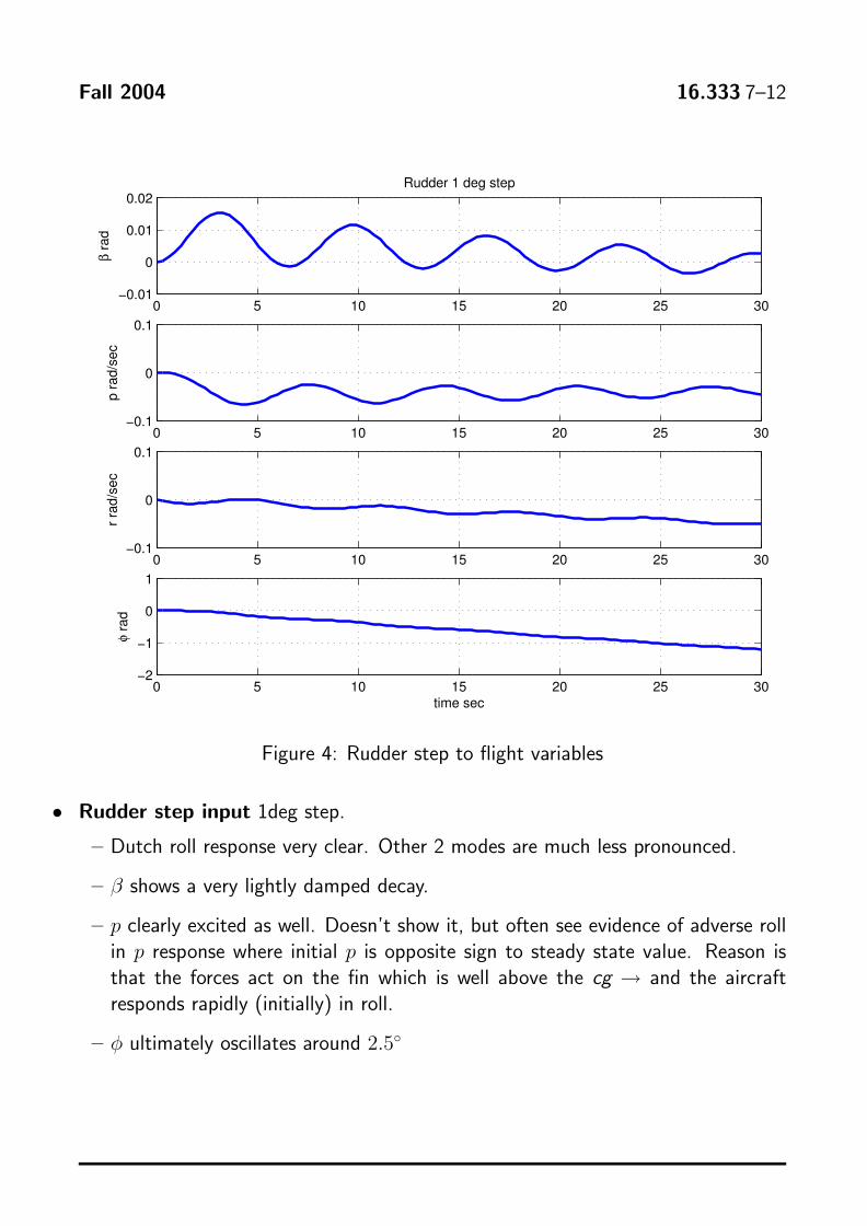
Figure 4: Rudder step to flight variables
• Rudder step input 1deg step.
– Dutch roll response very clear. Other 2 modes are much less pronounced.
– β shows a very lightly damped decay.
– p clearly excited as well. Doesn’t show it, but often see evidence of adverse roll in p response where initial p is opposite sign to steady state value. Reason is that the forces act on the fin which is well above the cg → and the aircraft responds rapidly (initially) in roll.
– φ ultimately oscillates around 2.5◦