π p at the J-PARC
22
-40 -20 0 20 40 100 50 0 -50 -100 (mm) π - K + Σ - Σ - p π - Hyperon-Proton Scattering at the J-PARC Motivation ‣ historic background ‣ YN scattering experiment at KEK-PS ‣ ... and at J-PARC Objective Method High-Speed Image Delay Tube ‣ What is it ? ‣ Characteristics & Performances expected a simulation IEIRI Masaharu これから研究会 09.02.21 @ Miyazaki
Transcript of π p at the J-PARC
-40 -20 0 20 40
100
50
0
-50
-100
(mm)
π-
K+
Σ-
Σ-
p
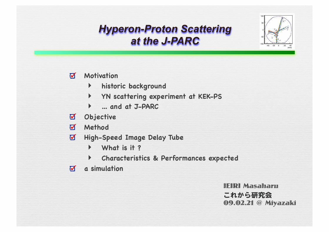
π-Hyperon-Proton Scattering at the J-PARC
Motivation‣ historic background‣ YN scattering experiment at KEK-PS‣ ... and at J-PARC
ObjectiveMethodHigh-Speed Image Delay Tube‣ What is it ?‣ Characteristics & Performances expected
a simulation
IEIRI Masaharuこれから研究会09.02.21 @ Miyazaki
-40 -20 0 20 40
100
50
0
-50
-100
(mm)
π-
K+
Σ-
Σ-
p
π-
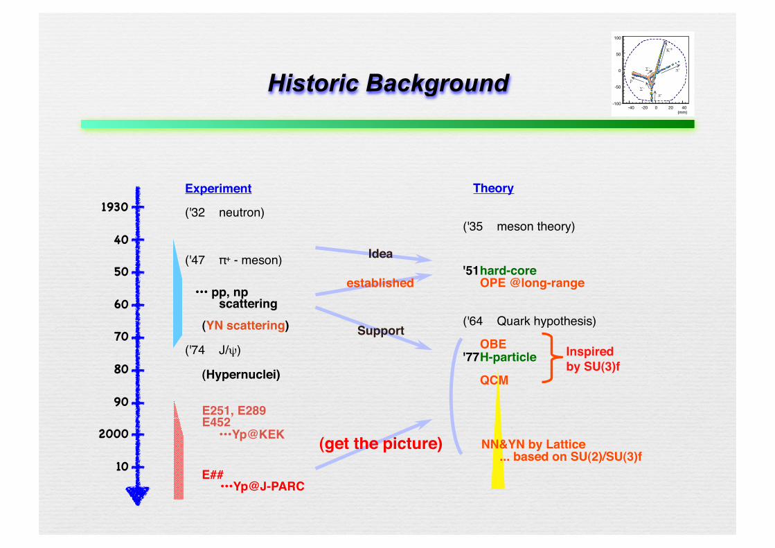
Historic Background
Idea
Experiment
('32 neutron)
('47 π+ - meson)
••• pp, np scattering (YN scattering)
('74 J/ψ)
(Hypernuclei)
E251, E289 E452 •••Yp@KEK
Theory
('35 meson theory)
'51 hard-core OPE @long-range
('64 Quark hypothesis)
OBE '77 H-particle
QCM
NN&YN by Lattice... based on SU(2)/SU(3)f
Inspired by SU(3)f
(get the picture)
established
Support
1930
40
50
60
70
80
90
2000
10 E##•••Yp@J-PARC
-40 -20 0 20 40
100
50
0
-50
-100
(mm)
π-
K+
Σ-
Σ-
p
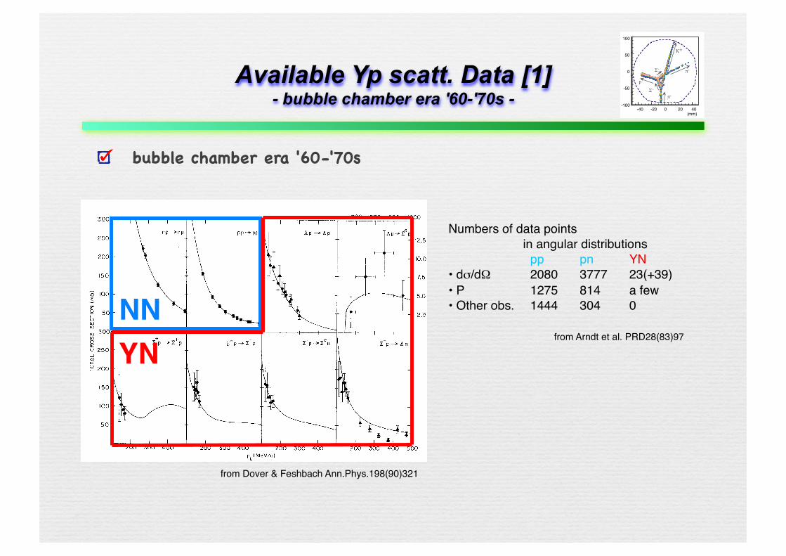
π-Available Yp scatt. Data [1]- bubble chamber era '60-'70s -
bubble chamber era '60-'70s
NNYN
Numbers of data points in angular distributions
pp pn YN• dσ/dΩ 2080 3777 23(+39)• P 1275 814 a few• Other obs. 1444 304 0
from Arndt et al. PRD28(83)97
from Dover & Feshbach Ann.Phys.198(90)321
-40 -20 0 20 40
100
50
0
-50
-100
(mm)
π-
K+
Σ-
Σ-
p
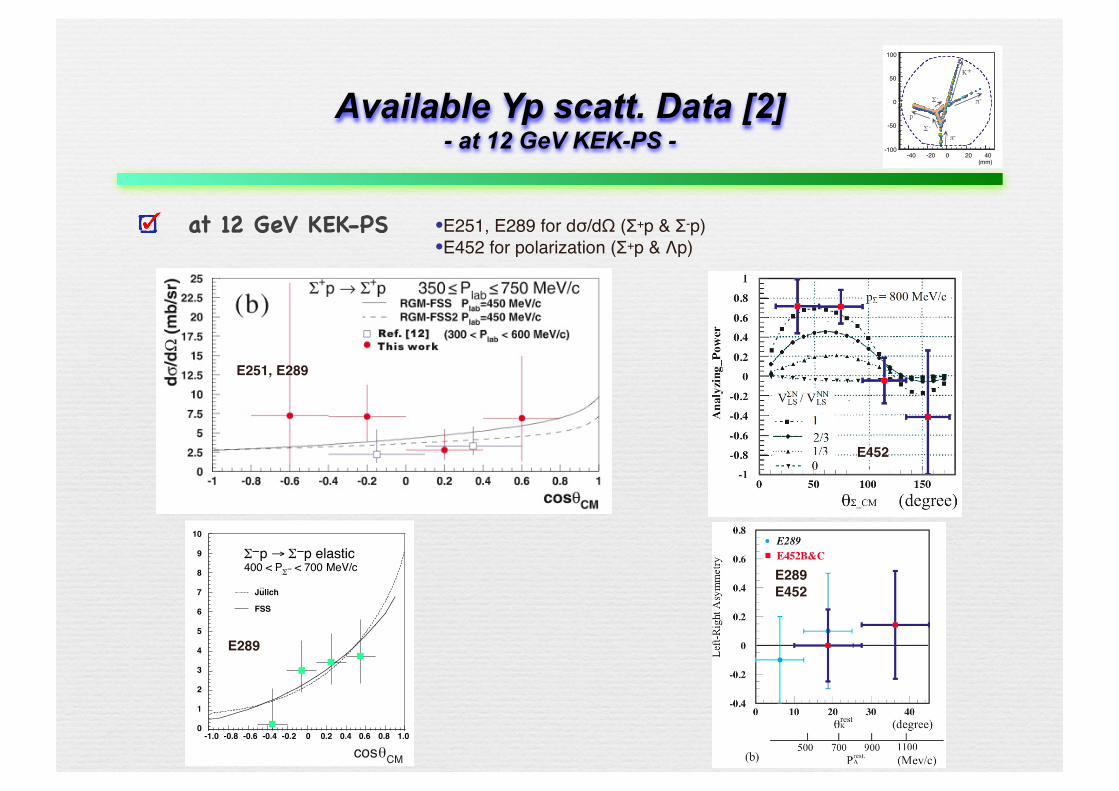
π-Available Yp scatt. Data [2]- at 12 GeV KEK-PS -
at 12 GeV KEK-PS E251, E289 for dσ/dΩ (Σ+p & Σ-p) E452 for polarization (Σ+p & Λp)
cosθCM
Julich
FSS
10
9
8
7
6
5
4
3
2
1
0-1.0 -0.8 -0.6 -0.4 -0.2 0 0.2 0.4 0.6 0.8 1.0
Σ−p → Σ−p elastic400 < PΣ− < 700 MeV/c
..
E289
E251, E289
E289E452
E452
-40 -20 0 20 40
100
50
0
-50
-100
(mm)
π-
K+
Σ-
Σ-
p
π-
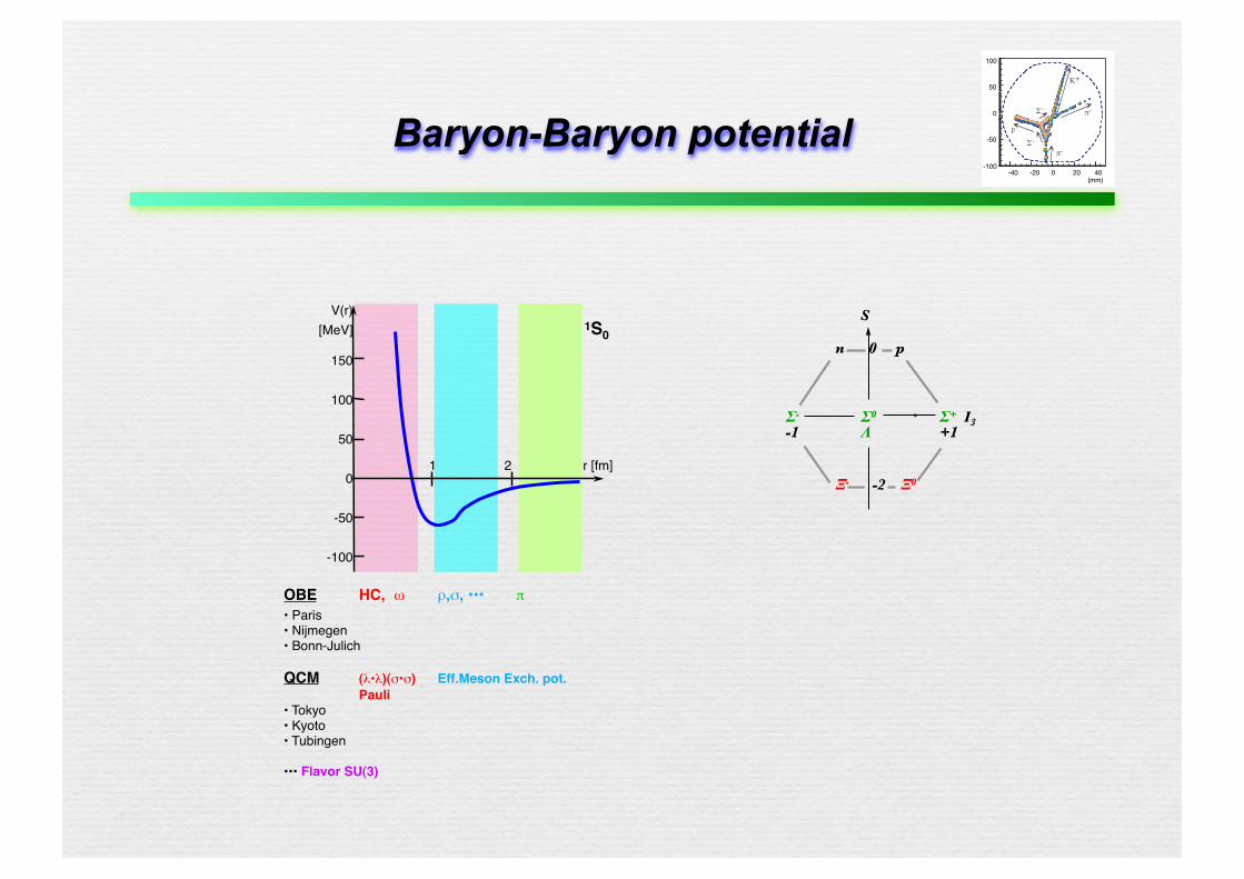
Baryon-Baryon potential
V(r)[MeV]
150
100
50
0
-50
-100
1 2 r [fm]
1S0
OBE HC, �ω ρ,σ, ••• π• Paris • Nijmegen • Bonn-Julich
QCM (λ•λ)(σ•σ) Eff.Meson Exch. pot. Pauli • Tokyo• Kyoto• Tubingen
••• Flavor SU(3)
S
n 0 p
Σ- Σ0 Σ+ I3
-1 Λ +1
Ξ- -2 Ξ0
-40 -20 0 20 40
100
50
0
-50
-100
(mm)
π-
K+
Σ-
Σ-
p
π-
Baryon-Baryon potential
V(r)[MeV]
150
100
50
0
-50
-100
1 2 r [fm]
1S0
OBE HC, �ω ρ,σ, ••• π• Paris • Nijmegen • Bonn-Julich
QCM (λ•λ)(σ•σ) Eff.Meson Exch. pot. Pauli • Tokyo• Kyoto• Tubingen
••• Flavor SU(3)
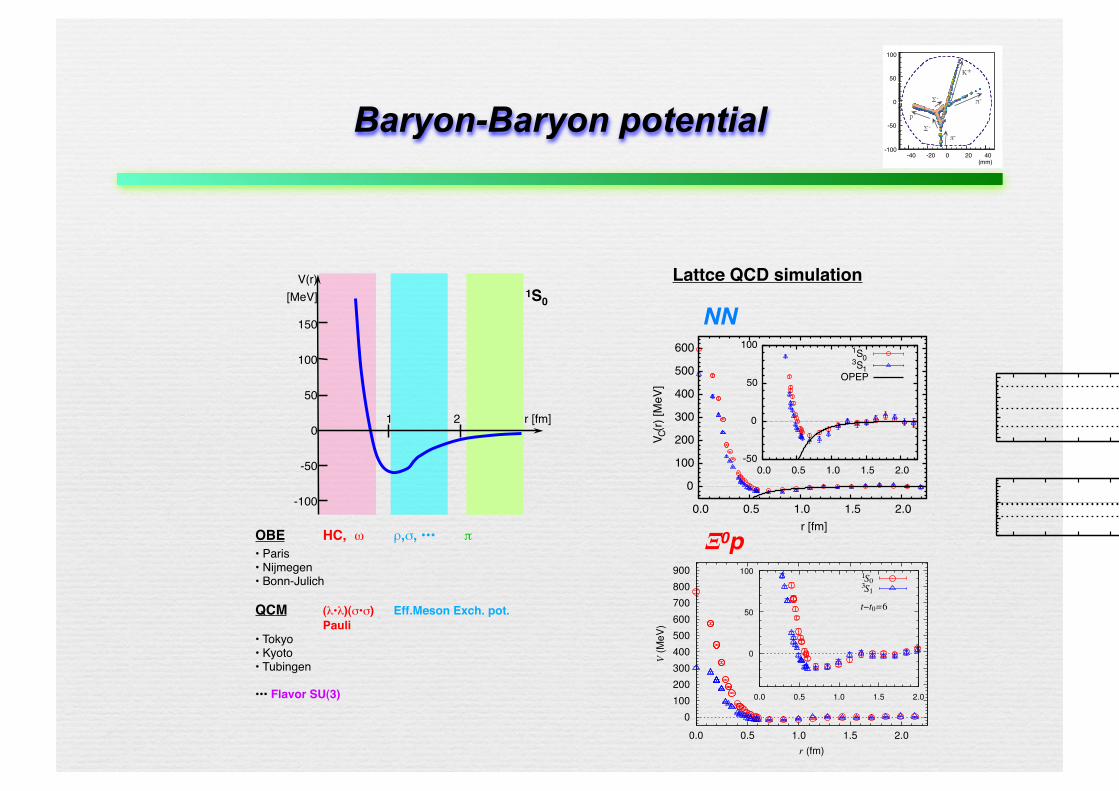
beyond which we plot only the data locating on the coor-dinate axes and their nearest neighbors. As is clear fromFig. 2, the wave function is suppressed at short distanceand has a slight enhancement at medium distance, whichsuggests that the NN system has a repulsion (attraction) atshort (medium) distance.
Figure 3 shows the central (effective central) NN poten-tial in the 1S0 (3S1) channel at t! t0 " 6. As for r2 inEq. (2), we take the discrete form of the Laplacian with thenearest-neighbor points. E is obtained from the Green’sfunction G# ~r;E$ which is a solution of the Helmholtzequation on the lattice [9]. By fitting the wave function!#~r$ at the points ~r " #10–16; 0; 0$ and #10–16; 1; 0$ byG#~r;E$, we obtain E#1S0$"!0:49#15$MeV and E#3S1$ "
!0:67#18$ MeV. Namely, there is a slight attraction be-tween the two nucleons in a finite box. To make an inde-pendent check of the ground state saturation, we plot the tdependence of VC#r$ in the 1S0 channel at several distancesr " 0, 0.14, 0.19, 0.69, 1.37, and 2.19 fm in Fig. 4. Thesaturation indeed holds for t! t0 % 6 within errors.
As anticipated from Fig. 2, VC#r$ and VeffC #r$ have
repulsive core at r & 0:5 fm with the height of about afew hundred MeV. Also, they have an attraction of about!#20–30$ MeV at the distance 0:5 & r & 1:0 fm. Thesolid lines in Fig. 3 show the one-pion exchange contribu-tion to the central potential calculated from
V"C #r$ "
g2"N4"
# ~#1 & ~#2$# ~$1 & ~$2$3
!m"
2mN
"2 e!m"r
r; (5)
where we have used m" ’ 0:53 GeV and mN ’ 1:34 GeVto be consistent with our data, while the physical value ofthe "N coupling constant is used, g2"N=#4"$ ’ 14:0. Evenin the quenched approximation, the one-pion exchange ispossible as the connected quark exchange between the twonucleons. In addition, there is in principle a quenchedartifact to the NN potential from the flavor-singlet hairpindiagram (the ghost exchange) between the nucleons [13].Its contribution to the central potential reads [14]: V%
C #r$ "g2%N4"
~$1& ~$23 # m"
2mN$2#1r !
m20
2m"$e!m"r. Here g%N and m0 are the
%N coupling constant and a mass parameter of the ghost,respectively. The ghost potential has an exponential tailwhich dominates over the Yukawa potential at large dis-tances. Its significance can be estimated by comparing thesign and the magnitude of em"rVC#r$ and em"rVeff
C #r$ atlarge distances, because V%
C #r$ has an opposite sign be-tween 1S0 and 3S1. Our present data show no evidence ofthe ghost at large distances within errors, which mayindicate g%N ' g"N .
Several comments are in order here. (1) The asymptoticwave function at low energy (E ! 0) is approximated as!asy#r$" sin(kr)&0#k$*
kr ! r)a0r , where &0#k$ (a0) is the s-wave
0.0
0.2
0.4
0.6
0.8
1.0
1.2
0.0 0.5 1.0 1.5 2.0
NN
wav
e fu
nctio
n φ(
r)
r [fm]
1S03S1
-2 -1 0 1 2 -2-1
01
20.5
1.0
1.5φ(x,y,z=0;1S0)
x[fm] y[fm]
φ(x,y,z=0;1S0)
FIG. 2 (color online). The lattice QCD result of the radialdependence of the NN wave function at t! t0 " 6 in the 1S0and 3S1 channels. Inset shows the two-dimensional view in thex! y plane.
0
100
200
300
400
500
600
0.0 0.5 1.0 1.5 2.0
V C(r
) [M
eV]
r [fm]
-50
0
50
100
0.0 0.5 1.0 1.5 2.0
1S03S1OPEP
FIG. 3 (color online). The lattice QCD result of the central(effective central) part of the NN potential VC#r$ [Veff
C #r$] in the1S0 (3S1) channel for m"=m' " 0:595. The inset shows itsenlargement. The solid lines correspond to the one-pion ex-change potential (OPEP) given in Eq. (5).
300
400
500
600
2 3 4 5 6 7 8
V C(r
) [M
eV] r=0.00fm
r=0.14fm
r=0.19fm
-40-20 0
20
2 3 4 5 6 7 8
V C(r
) [M
eV]
t-t0 [lattice unit]
r=0.69fm
r=1.37fm r=2.19fm
FIG. 4 (color online). t! t0 dependence of VC#r$ in the 1S0channel for several different values of the distance r.
PRL 99, 022001 (2007) P H Y S I C A L R E V I E W L E T T E R S week ending13 JULY 2007
022001-3
0.5
1.0
0.0 0.5 1.0 1.5 2.0
r (fm)
t!t0=6
1
3
1
3
S0S1
G(r",k2( S0))
G(r",k2( S1))
1.00
1.05
1.0 1.5 2.0 0
100
200
300
400
500
600
700
800
900
0.0 0.5 1.0 1.5 2.0
V (
MeV
)
r (fm)
t!t0=6
1
3
0
50
100
0.0 0.5 1.0 1.5 2.0
S0S1
Fig. 1. (Left) The radial wave function of pΞ0, in 1S0 (circle) and 3S1 (triangle) channels, obtained at t− t0 = 6. The Green’sfunctions G(!r, k2) with !r = (r, 0, 0) in 1S0 (solid line) and 3S1 (dotted line) are also shown. The inset shows its enlargement.(Right) The effective central potential for pΞ0, in the 1S0 (circle) and 3S1 (triangle), obtained from the wave function at timeslice t − t0 = 6. The inset shows its enlargement.
spatial boundary !r = (32/2, 0, 0). For r <∼ 0.7 fm, the wave function is calculated for all possible values of !r,while, for the outer region, it is calculated only on the x, y, z axis and their nearest neighbors to reduce thenumerical cost.
As seen in the Figure, the wave functions are suppressed at short distance and are slightly enhanced atmedium distance in both 1S0 and 3S1 channels. There is a sizable difference of the suppression pattern atshort distance between 1S0 and 3S1; the repulsion is stronger in the 1S0 channel.
4.2. central potential
To derive the NΞ potential through Eq. (9), we need to know the non-relativistic energy E = k2/(2µ). Ithas been shown in Ref. [23] that k2 and thus E can be accurately determined by fitting the wave functionin the asymptotic region in terms of the lattice Green’s function
G(!r, k2) =1
L3
∑
!p∈Γ
1
p2 − k2ei!p·!r, Γ =
{
!p; !p = !n2π
L,!n ∈ Z
3
}
, (13)
which is the solution of ($ + k2)G(!r, k2) = −δL(!r) with δL(!r) being the periodic delta function [10,23].Results of the fit in the range (12 ≤ x ≤ 16, 0 ≤ y ≤ 1, z = 0) are shown in the left panel of Fig. 1. Thefitting range is determined so that it is outside the range of the interaction (see the right panel of Fig. 1). Thenon-relativistic energies thus obtained in the 1S0 (3S1) channel becomes E = −0.4(2) MeV (E = −0.8(2)MeV). We have checked that the results of the fit in different ranges 11 ≤ x ≤ 16 and 13 ≤ x ≤ 16 introducesystematic errors only less than half of the statistical errors for E. Note that E can be negative for thescattering state in a finite box if the interaction is attractive.
The effective central potentials for pΞ0 system obtained from Eq. (9) with the wave function φ and theenergy E at t − t0 = 6 are shown in the right panel of Fig. 1 for the 1S0 and 3S1 channels at mπ & 368
κud κs Nconf mπ mρ mK mK∗ mφ mp mΞ0 mΛ mΣ+
0.1665 0.1643 1000 511.2(6) 861(2) 605.3(5) 904(2) 946(1) 1300(4) 1419(4) 1354(4) 1375(4)
0.1678 0.1643 1283 368(1) 813(4) 554.0(5) 884(2) 946(1) 1167(7) 1383(6) 1266(6) 1315(6)
Exp. 135 770 494 892 1019 940 1320 1116 1190
Table 1Hadron masses in the unit of MeV calculated for the hopping parameters κud and κs, with the number of gauge configurationsNconf .
5
NN
Ξ0p
Lattce QCD simulation
-40 -20 0 20 40
100
50
0
-50
-100
(mm)
π-
K+
Σ-
Σ-
p
π-
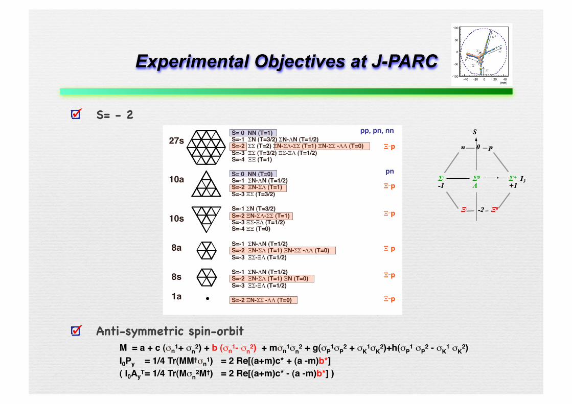
Experimental Objectives at J-PARC
S= - 2
Anti-symmetric spin-orbitM = a + c (σn1+ σn
2) + b (σn1- σn2) + mσn1σn
2 + g(σP1σP
2 + σK1σK
2)+h(σP1 σP
2 - σK1 σK
2) I0Py = 1/4 Tr(MM†σn1) = 2 Re[(a+m)c* + (a -m)b*]( I0AyT = 1/4 Tr(Mσn
2M†) = 2 Re[(a+m)c* - (a -m)b*] )
27s
10a
10s
8a
8s
1a
S= 0 NN (T=1)S=-1 ΣN (T=3/2) ΣN-ΛN (T=1/2)S=-2 ΣΣ (T=2) ΞN-ΣΛ-ΣΣ (T=1) ΞN-ΣΣ -ΛΛ (T=0) S=-3 ΞΣ (T=3/2) ΞΣ-ΞΛ (T=1/2) S=-4 ΞΞ (T=1)
S= 0 NN (T=0)S=-1 ΣN-ΛN (T=1/2)S=-2 ΞN-ΣΛ (T=1)S=-3 ΞΣ (T=3/2)
S=-1 ΣN (T=3/2) S=-2 ΞN-ΣΛ-ΣΣ (T=1) S=-3 ΞΣ-ΞΛ (T=1/2) S=-4 ΞΞ (T=0)
S=-1 ΣN-ΛN (T=1/2)S=-2 ΞN-ΣΛ (T=1) ΞN-ΣΣ -ΛΛ (T=0) S=-3 ΞΣ-ΞΛ (T=1/2)
S=-1 ΣN-ΛN (T=1/2)S=-2 ΞN-ΣΛ (T=1) ΞN (T=0) S=-3 ΞΣ-ΞΛ (T=1/2)
S=-2 ΞN-ΣΣ -ΛΛ (T=0)
pp, pn, nn
pn
Ξ−p
Ξ−p
Ξ−p
Ξ−p
Ξ−p
Ξ−p
S
n 0 p
Σ- Σ0 Σ+ I3
-1 Λ +1
Ξ- -2 Ξ0
-40 -20 0 20 40
100
50
0
-50
-100
(mm)
π-
K+
Σ-
Σ-
p
π-
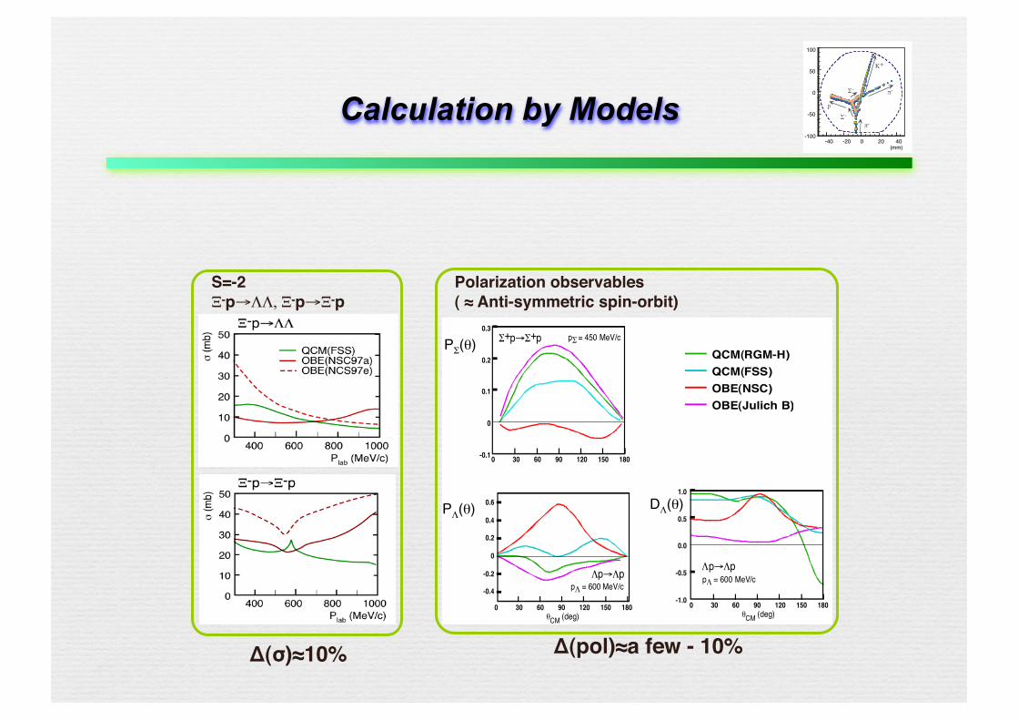
Calculation by Models
Σ+p→Σ+p pΣ = 450 MeV/c0.3
0.2
0.1
0
-0.10 30 60 90 120 150 180
0 30 60 90 120 150 180θCM (deg)
1.0
0.5
0.0
-0.5
-1.0
Λp→ΛppΛ = 600 MeV/c
0 30 60 90 120 150 180θCM (deg)
0.6
0.4
0.2
0
-0.2
-0.4
Λp→ΛppΛ = 600 MeV/c
S=-2 Ξ-p→ΛΛ, Ξ-p→Ξ-p
PΣ(θ)QCM(RGM-H)QCM(FSS)OBE(NSC)OBE(Julich B)
PΛ(θ) DΛ(θ)
Polarization observables ( ≈ Anti-symmetric spin-orbit)
Δ(σ)≈10% Δ(pol)≈a few - 10%
-40 -20 0 20 40
100
50
0
-50
-100
(mm)
π-
K+
Σ-
Σ-
p
π-
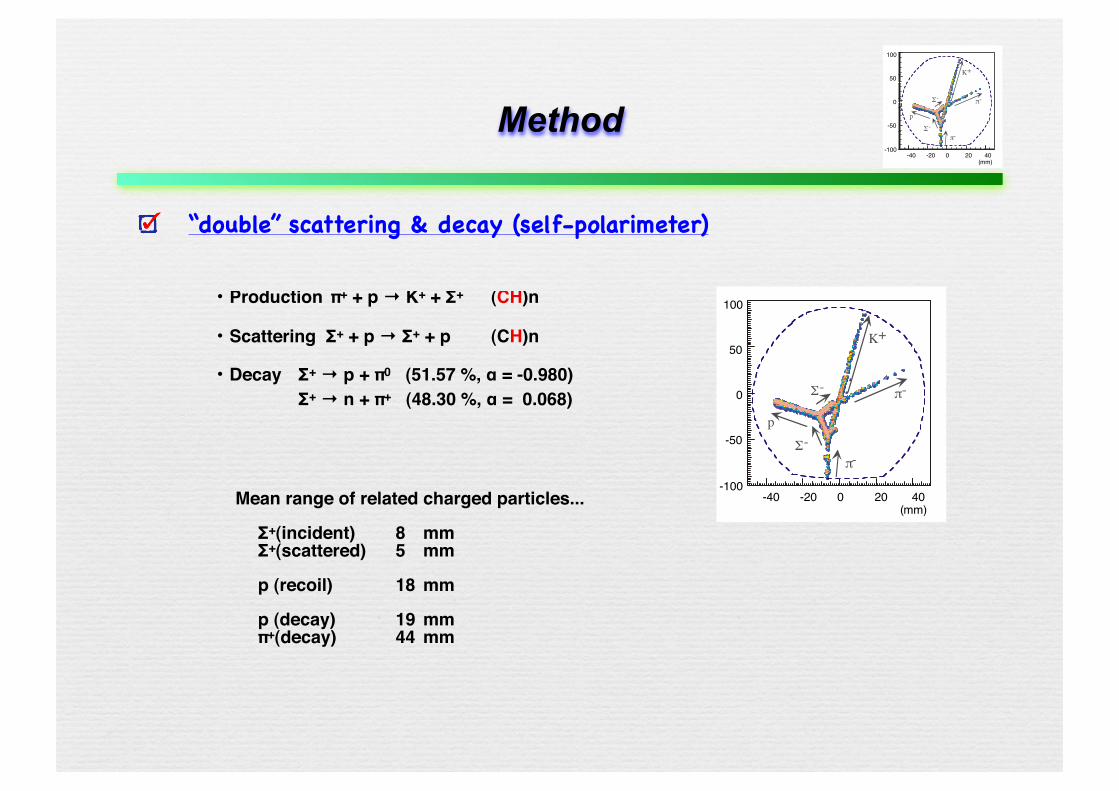
Method
“double” scattering & decay (self-polarimeter)
・ Production π+ + p → K+ + Σ+ (CH)n
・ Scattering Σ+ + p → Σ+ + p (CH)n
・ Decay Σ+ → p + π0 (51.57 %, α = -0.980) Σ+ → n + π+ (48.30 %, α = 0.068)
-40 -20 0 20 40
100
50
0
-50
-100
(mm)
π-
K+
Σ-
Σ-
p
π-
Mean range of related charged particles...
Σ+(incident) 8 mm Σ+(scattered) 5 mm
p (recoil) 18 mm
p (decay) 19 mm π+(decay) 44 mm
-40 -20 0 20 40
100
50
0
-50
-100
(mm)
π-
K+
Σ-
Σ-
p
π-
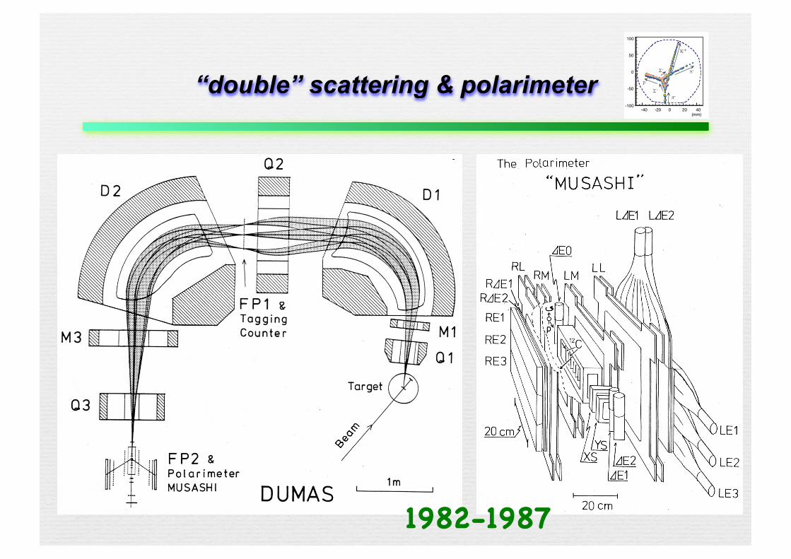
“double” scattering & polarimeter
1982-1987
-40 -20 0 20 40
100
50
0
-50
-100
(mm)
π-
K+
Σ-
Σ-
p
π-
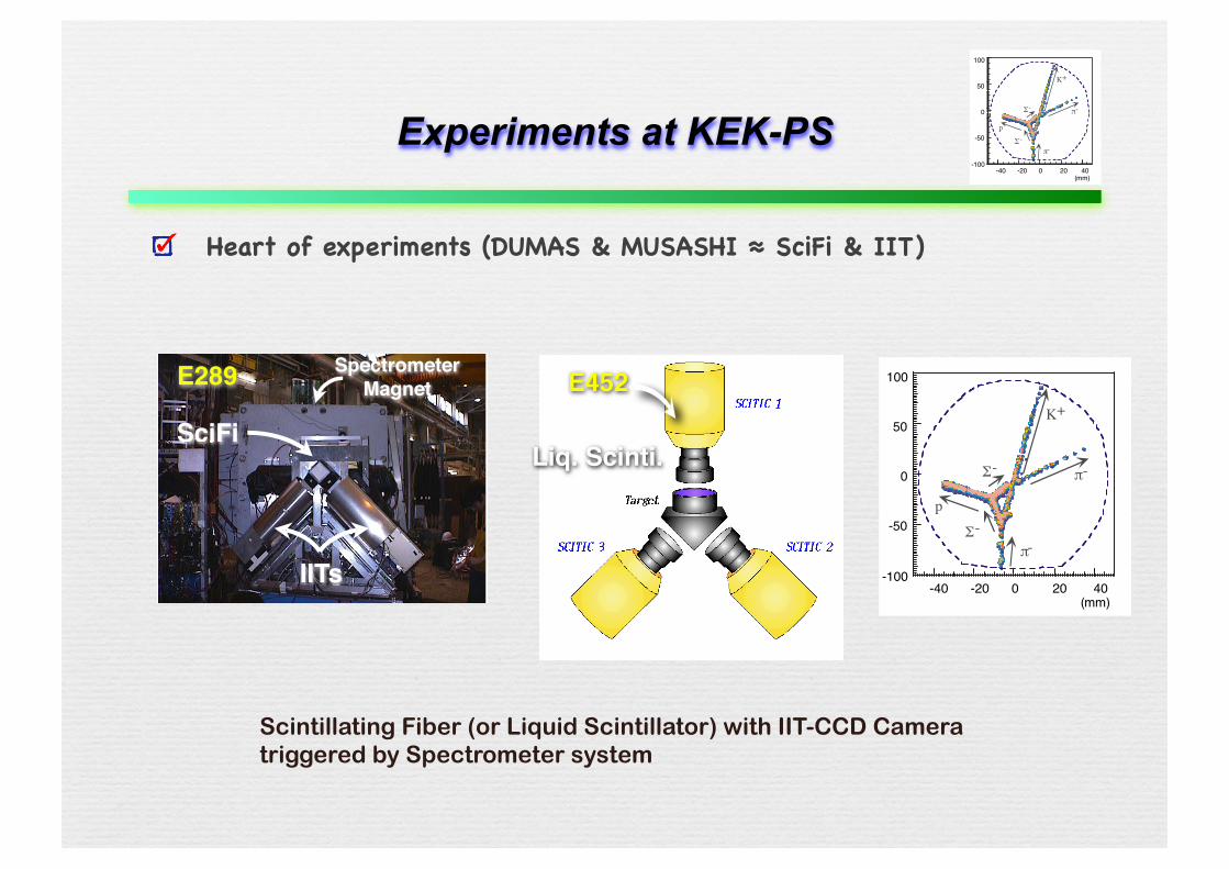
Experiments at KEK-PS
Heart of experiments (DUMAS & MUSASHI ≈ SciFi & IIT)
-40 -20 0 20 40
100
50
0
-50
-100
(mm)
π-
K+
Σ-
Σ-
p
π-
SpectrometerMagnet
SciFi
IITs
E289 E452
Liq. Scinti.
Scintillating Fiber (or Liquid Scintillator) with IIT-CCD Camera triggered by Spectrometer system
-40 -20 0 20 40
100
50
0
-50
-100
(mm)
π-
K+
Σ-
Σ-
p
π-
Experiments at KEK-PS
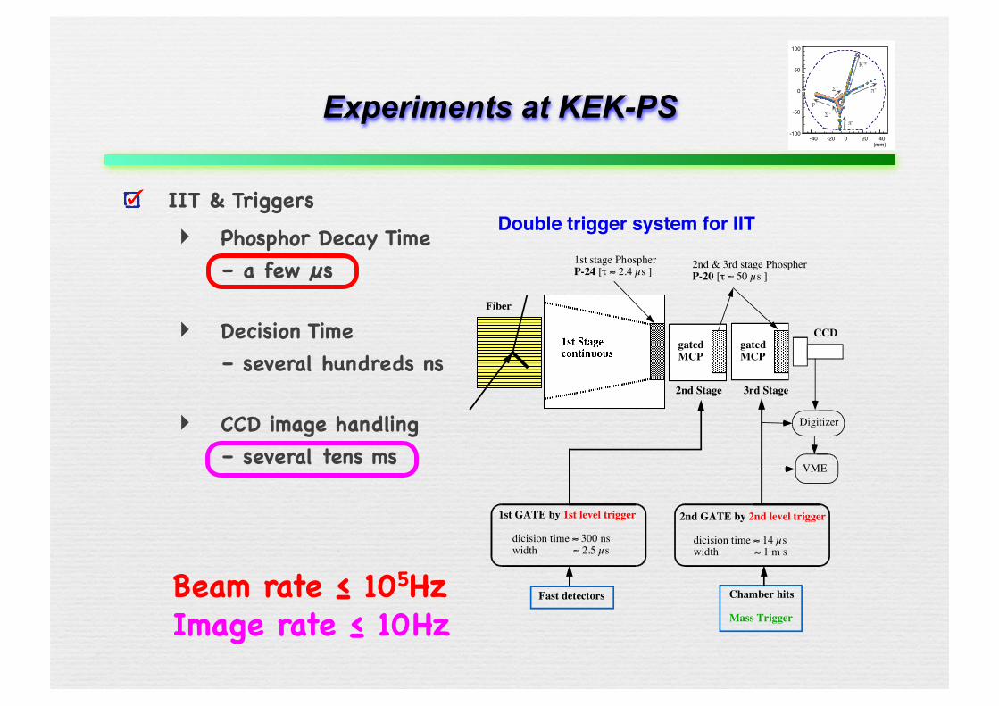
IIT & Triggers‣ Phosphor Decay Time
– a few µs
‣ Decision Time– several hundreds ns
‣ CCD image handling– several tens ms
gatedMCP
Fiber
2nd Stage 3rd Stage
Double trigger system for IIT
2nd & 3rd stage PhospherP-20 [! " 50 µs ]
gatedMCP
CCD
1st stage PhospherP-24 [! " 2.4 µs ]
1st GATE by 1st level trigger
dicision time " 300 nswidth " 2.5 µs
2nd GATE by 2nd level trigger
dicision time " 14 µswidth " 1 m s
Fast detectors Chamber hits
Mass Trigger
Digitizer
VME
Beam rate ≤ 105HzImage rate ≤ 10Hz
-40 -20 0 20 40
100
50
0
-50
-100
(mm)
π-
K+
Σ-
Σ-
p
π-
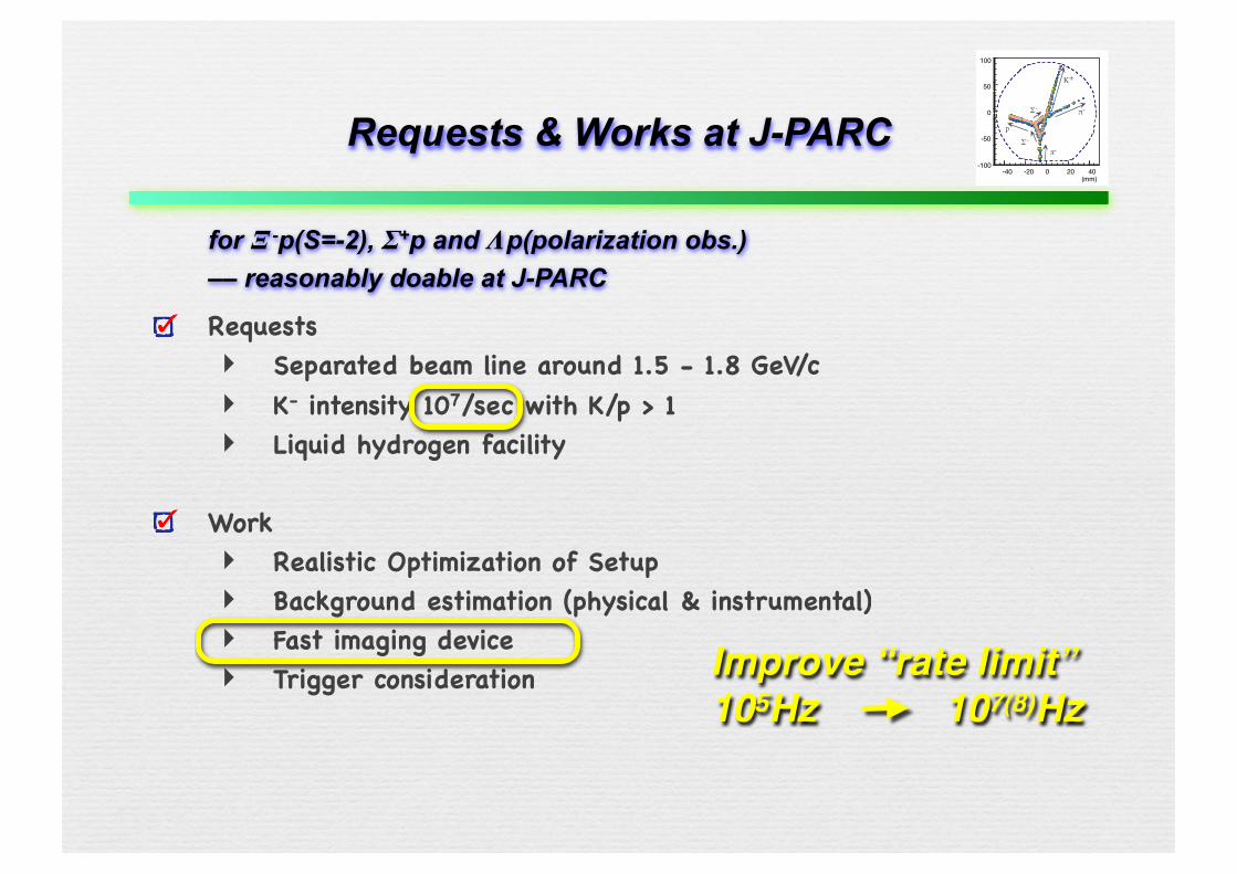
Requests & Works at J-PARC
for Ξ -p(S=-2), Σ+p and Λp(polarization obs.) –– reasonably doable at J-PARC
Requests‣ Separated beam line around 1.5 - 1.8 GeV/c‣ K- intensity 107/sec with K/p > 1‣ Liquid hydrogen facility
Work‣ Realistic Optimization of Setup‣ Background estimation (physical & instrumental)‣ Fast imaging device‣ Trigger consideration Improve “rate limit”
105Hz 107(8)Hz
-40 -20 0 20 40
100
50
0
-50
-100
(mm)
π-
K+
Σ-
Σ-
p
π-High-Speed Image Delay Tube- What is it ? -
Prototypes‣ ON THE OPTOELECTRONIC SCHEME OF A SCINTILLATING FIBRE TRACKING
DETECTOR FOR FUTURE LARGE HADRON COLLIDERJ.P.Fabre, T.Gys and M.Primout: CERN/EF/4147H/TG/mnb 8 November 1988
‣ THE BASIC PRINCIPLE OF A VACUUM IMAGE PIPELINET. Gys : CERN/EF/4304H/TG/mnb 12 January 1989
‣ Conceptual design for an optelectric delay lineJ.P.Fabre, T.Gys, M.Primout and L.Van hamme: Revue Phys. Appl. 24(1989)1019
‣ OPTOELECTRONIC DELAY FOR THE READ-OUT OF PARTICLE TRACKS FROM SCINTILLATING FIBREST. Gys et al. : CERN/EF 89-25, DERN/LAA-SF91-3, CERN/DRDC 92-42
‣ OPTO-ELECTRIC DELAY TUBEST. Gys et al. : DERN/LAA/SF 90-20
‣ A high-speed gateable image pipeline Berkovski et. al. NIM A380(1996)537
-40 -20 0 20 40
100
50
0
-50
-100
(mm)
π-
K+
Σ-
Σ-
p
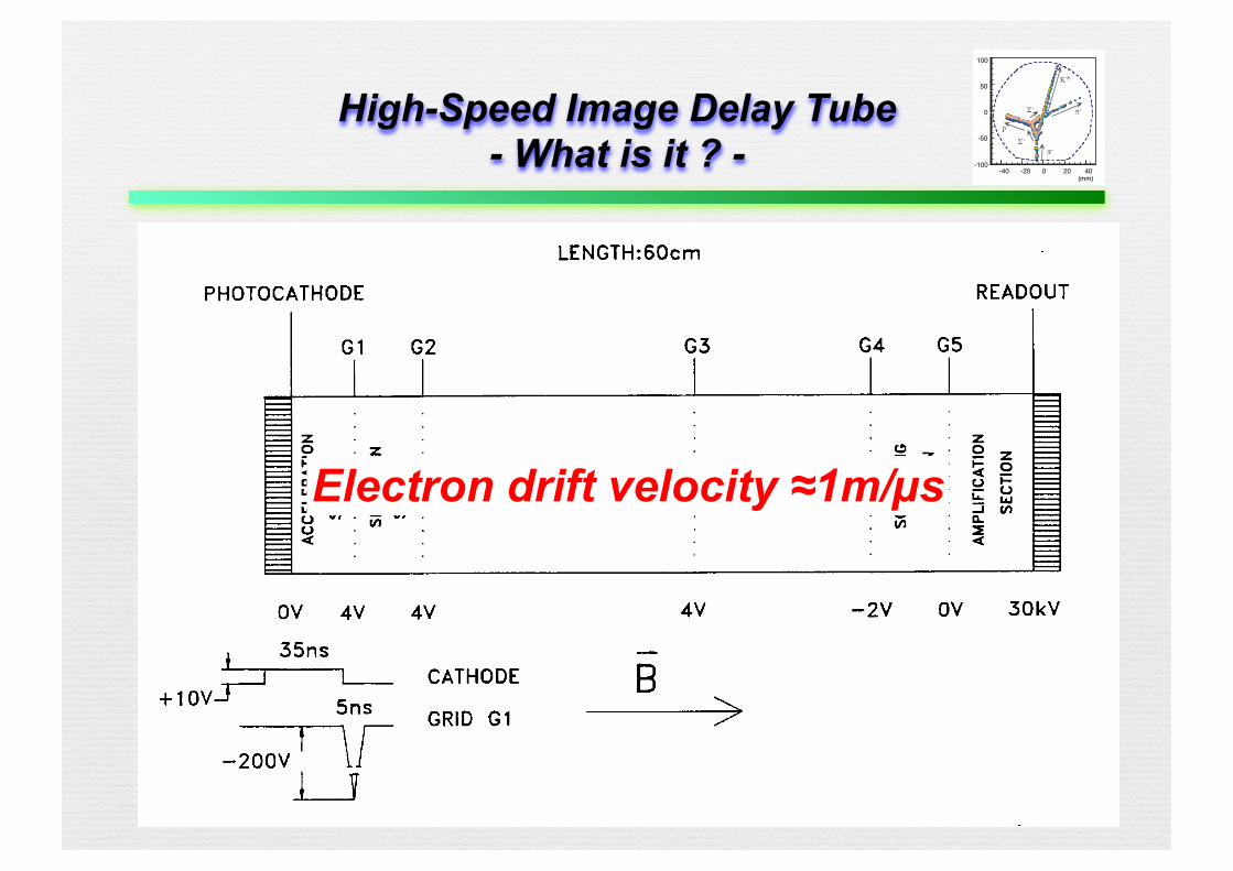
π-High-Speed Image Delay Tube- What is it ? -
Prototypes‣ ON THE OPTOELECTRONIC SCHEME OF A SCINTILLATING FIBRE TRACKING
DETECTOR FOR FUTURE LARGE HADRON COLLIDERJ.P.Fabre, T.Gys and M.Primout: CERN/EF/4147H/TG/mnb 8 November 1988
‣ THE BASIC PRINCIPLE OF A VACUUM IMAGE PIPELINET. Gys : CERN/EF/4304H/TG/mnb 12 January 1989
‣ Conceptual design for an optelectric delay lineJ.P.Fabre, T.Gys, M.Primout and L.Van hamme: Revue Phys. Appl. 24(1989)1019
‣ OPTOELECTRONIC DELAY FOR THE READ-OUT OF PARTICLE TRACKS FROM SCINTILLATING FIBREST. Gys et al. : CERN/EF 89-25, DERN/LAA-SF91-3, CERN/DRDC 92-42
‣ OPTO-ELECTRIC DELAY TUBEST. Gys et al. : DERN/LAA/SF 90-20
‣ A high-speed gateable image pipeline Berkovski et. al. NIM A380(1996)537
Electron drift velocity ≈1m/µs
-40 -20 0 20 40
100
50
0
-50
-100
(mm)
π-
K+
Σ-
Σ-
p
π-KEK - HSIDT(High-Speed Image Delay Tube)
1. Visit Dr. T.Gys at CERN in June ... learn things and hints ...
2. examine the structure of a tube, and decide to assemble as a sectional detector ... drawing & drawing & ...
‣ Input photocathode and output phosphor, grids, field-shaping electrodes, ceramic insulation, solenoid magnet, pulse generator, ...
3. now assembling and test will be started soon ...
-40 -20 0 20 40
100
50
0
-50
-100
(mm)
π-
K+
Σ-
Σ-
p
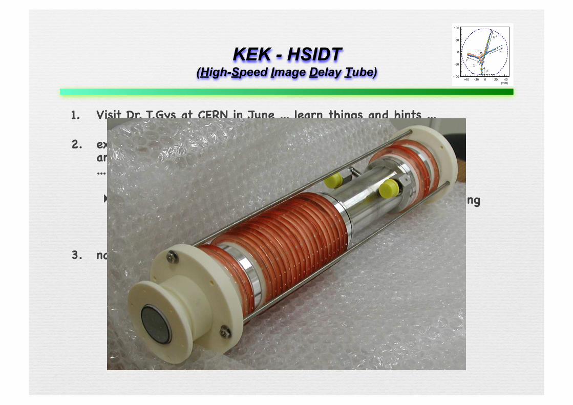
π-
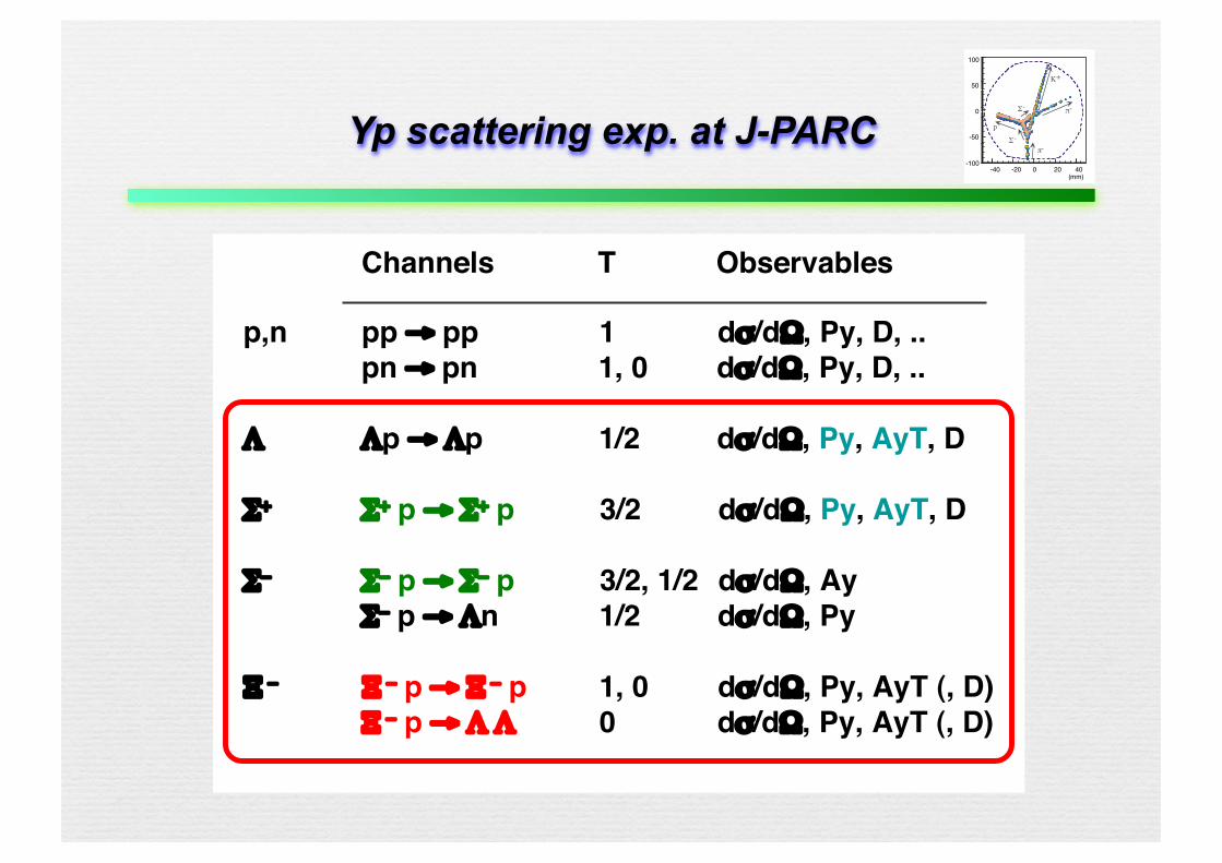
Yp scattering exp. at J-PARC
Channels T Observables
p,n pp → pp 1 dσ/dΩ, Py, D, ..pn → pn 1, 0 dσ/dΩ, Py, D, ..
Λ Λp → Λp 1/2 dσ/dΩ, Py, AyT, D
Σ+ Σ+ p → Σ+ p 3/2 dσ/dΩ, Py, AyT, D
Σ− Σ− p → Σ− p 3/2, 1/2 dσ/dΩ, AyΣ− p → Λn 1/2 dσ/dΩ, Py
Ξ − Ξ − p → Ξ − p 1, 0 dσ/dΩ, Py, AyT (, D)Ξ − p → Λ Λ 0 dσ/dΩ, Py, AyT (, D)
-40 -20 0 20 40
100
50
0
-50
-100
(mm)
π-
K+
Σ-
Σ-
p
π-
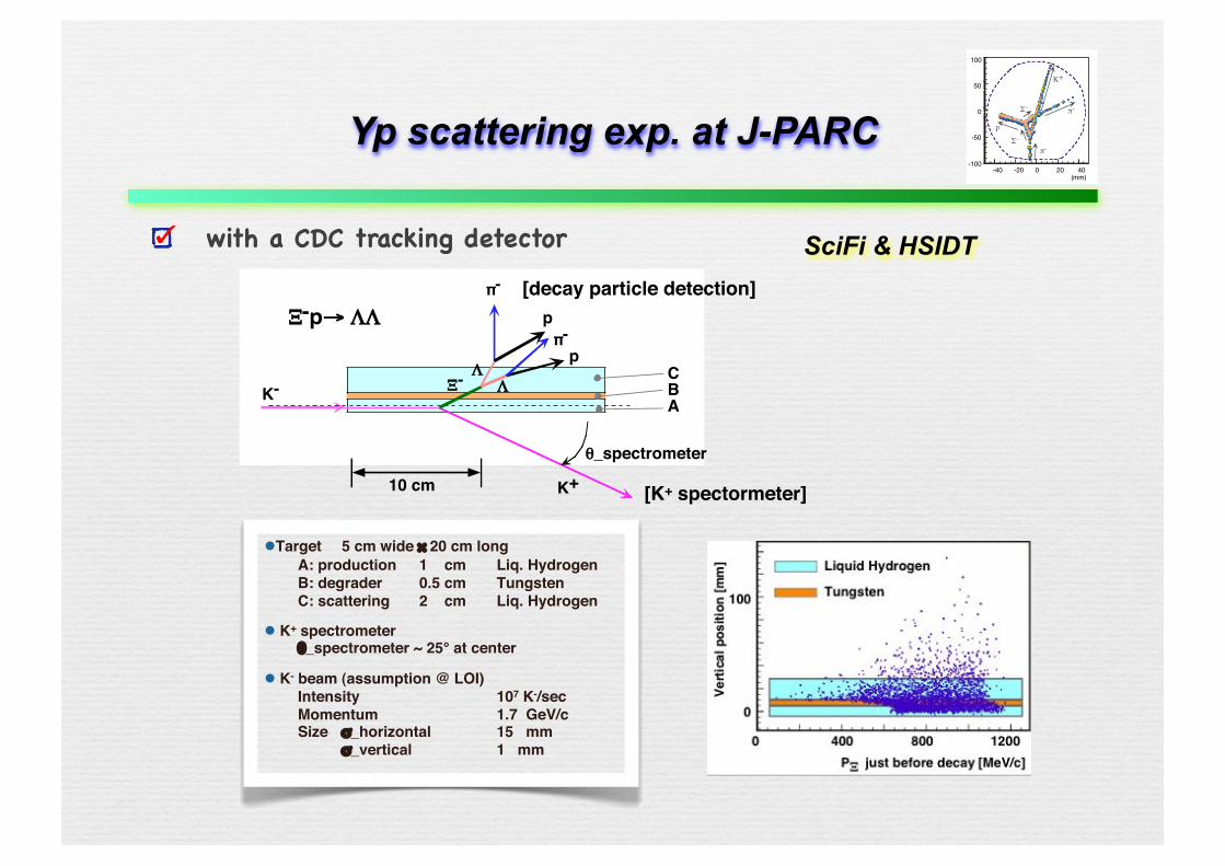
Yp scattering exp. at J-PARC
with a CDC tracking detector
Target 5 cm wide × 20 cm long A: production 1 cm Liq. Hydrogen B: degrader 0.5 cm Tungsten C: scattering 2 cm Liq. Hydrogen
K+ spectrometer θ_spectrometer ~ 25° at center
K- beam (assumption @ LOI) Intensity 107 K-/sec Momentum 1.7 GeV/c Size σ_horizontal 15 mm
σ_vertical 1 mm
K-
K+
π-
π-
p
p
ΛΛ
Ξ-
θ_spectrometer
10 cm
CBA
Ξ-p→ ΛΛ
[K+ spectormeter]
[decay particle detection]
SciFi & HSIDT
-40 -20 0 20 40
100
50
0
-50
-100
(mm)
π-
K+
Σ-
Σ-
p
π-
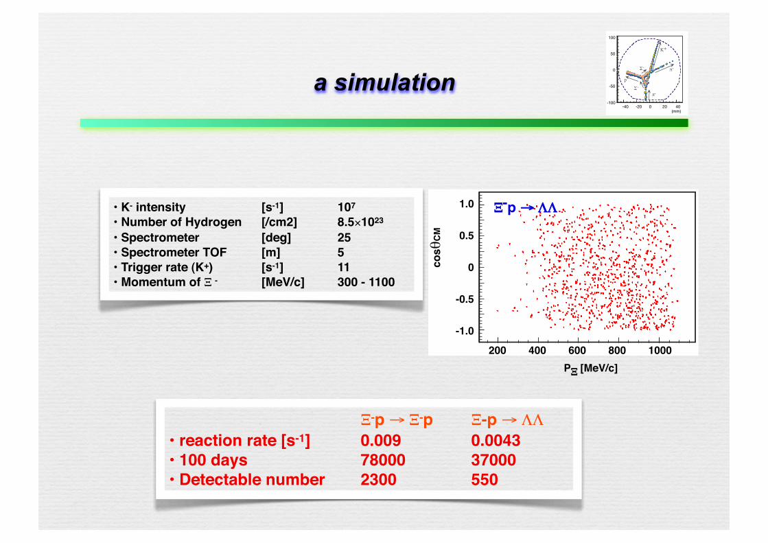
a simulation
• K- intensity [s-1] 107
• Number of Hydrogen [/cm2] 8.5×10²³ • Spectrometer [deg] 25• Spectrometer TOF [m] 5• Trigger rate (K+) [s-1] 11• Momentum of Ξ - [MeV/c] 300 - 1100
1.0
0.5
0
-0.5
-1.0
200 400 600 800 1000PΞ [MeV/c]
Ξ-p → ΛΛ
cosθ
CM Ξ-p → Ξ-p Ξ-p → ΛΛ• reaction rate [s-1] 0.009 0.0043• 100 days 78000 37000• Detectable number 2300 550
-40 -20 0 20 40
100
50
0
-50
-100
(mm)
π-
K+
Σ-
Σ-
p
π-
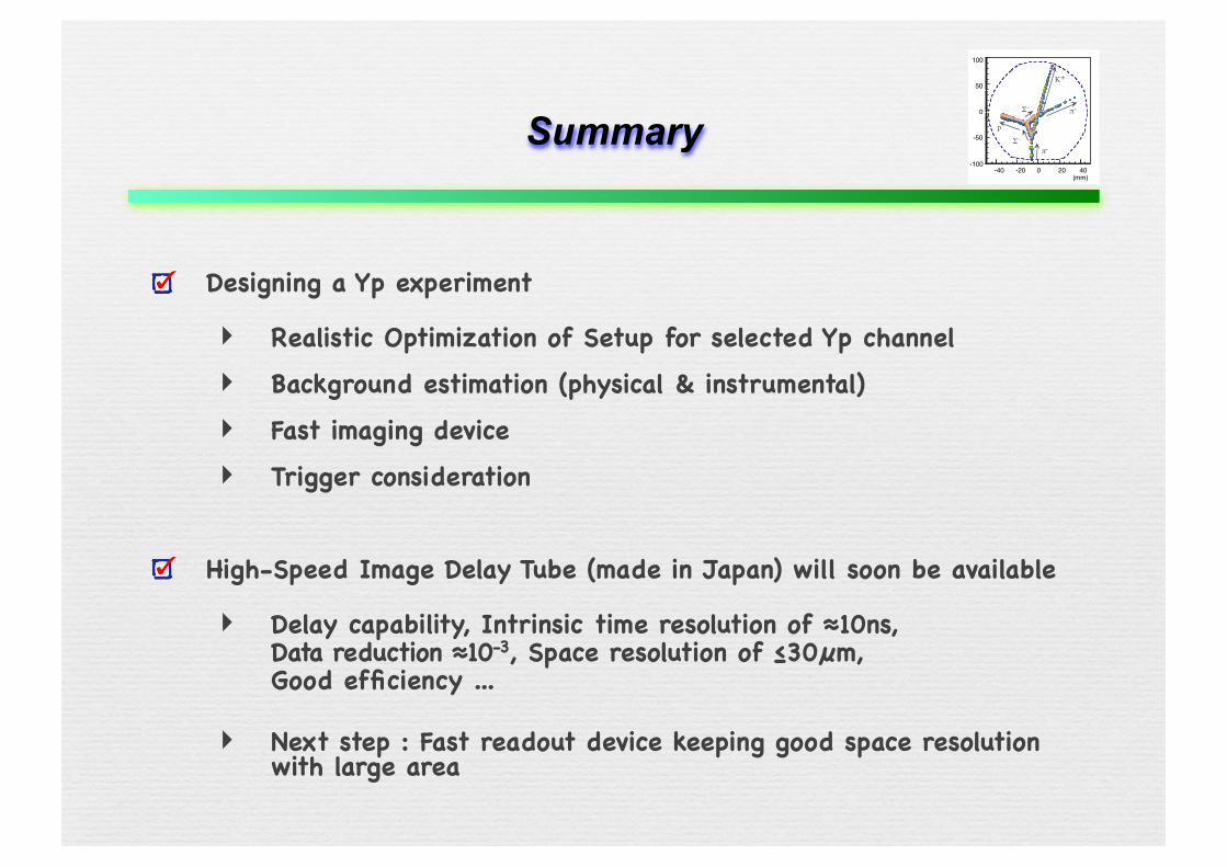
Summary
Designing a Yp experiment
‣ Realistic Optimization of Setup for selected Yp channel‣ Background estimation (physical & instrumental)‣ Fast imaging device‣ Trigger consideration
High-Speed Image Delay Tube (made in Japan) will soon be available
‣ Delay capability, Intrinsic time resolution of ≈10ns,Data reduction ≈10-3, Space resolution of ≤30µm,Good efficiency ...
‣ Next step : Fast readout device keeping good space resolution with large area
-40 -20 0 20 40
100
50
0
-50
-100
(mm)
π-
K+
Σ-
Σ-
p
π-
極限状態の物理
弾性散乱≈極低温反応
Yp弾性散乱≈これからの極低温反応@strangeness
“二回散乱”と“偏極”