Synchronous machines - montefiore.ulg.ac.begeuzaine/ELEC0431/3_Synchronous.pdfSynchronous machines 1...
16
Synchronous machines 1 Synchronous machines Turbo-alternator Saliant poles p / ω = θ ! Rotor (inductor) : 2p poles with excitation windings carrying DC current; non- laminated magnetic material Stator : polyphase (e.g. 3-phase) winding in slots; laminated magnetic material Synchronous generator (alternator): transforms mechanical energy into electric energy; designed to generate sinusoidal voltages and currents; used in most power plants, for car alternators, etc. Synchronous motor: transforms electric energy into mechanical energy; used for high- power applications (ships, original TGV…) ... 01/03/2018
Transcript of Synchronous machines - montefiore.ulg.ac.begeuzaine/ELEC0431/3_Synchronous.pdfSynchronous machines 1...

Synchronous machines 1
Synchronous machines
Turbo-alternator Saliant poles
p/ω=θ!Rotor (inductor) : 2p poles with excitationwindings carrying DC current; non-laminated magnetic material
Stator: polyphase (e.g. 3-phase) windingin slots; laminated magnetic material
Synchronous generator (alternator): transforms mechanical energy into electric energy;designed to generate sinusoidal voltages and currents; used in most power plants, for caralternators, etc.Synchronous motor: transforms electric energy into mechanical energy; used for high-power applications (ships, original TGV…)
...
01/03/2018

2
No-load characteristic
Evolution of the voltage Ev in a stator phasevs. intensity of the excitation current Ie, for agiven rotation speed and with no generatedstator current
⎩⎨⎧
=
=θ=
0Iconstantevitesse
avec)I(fE ev!
)I(kE evEv Φθ= !
Magnetic flux producedby the inductor and seen by the stator winding
Non linearity with hysteresis
due due remanent magnetization
• The rotor winding, carrying the DC current Ie and rotatingat speed ω/p, produces in the airgap a sliding m.m.f. Fe(as seen from the stator).
• Fe generates a magnetic flux density Br (with the samephase) in the airgap, which induces sinusoidal e.m.f.s Evin the stator windings, with a phase lag of π/2.
Synchronous machines
average characteristicaverage characteristic
withconstant speed
3
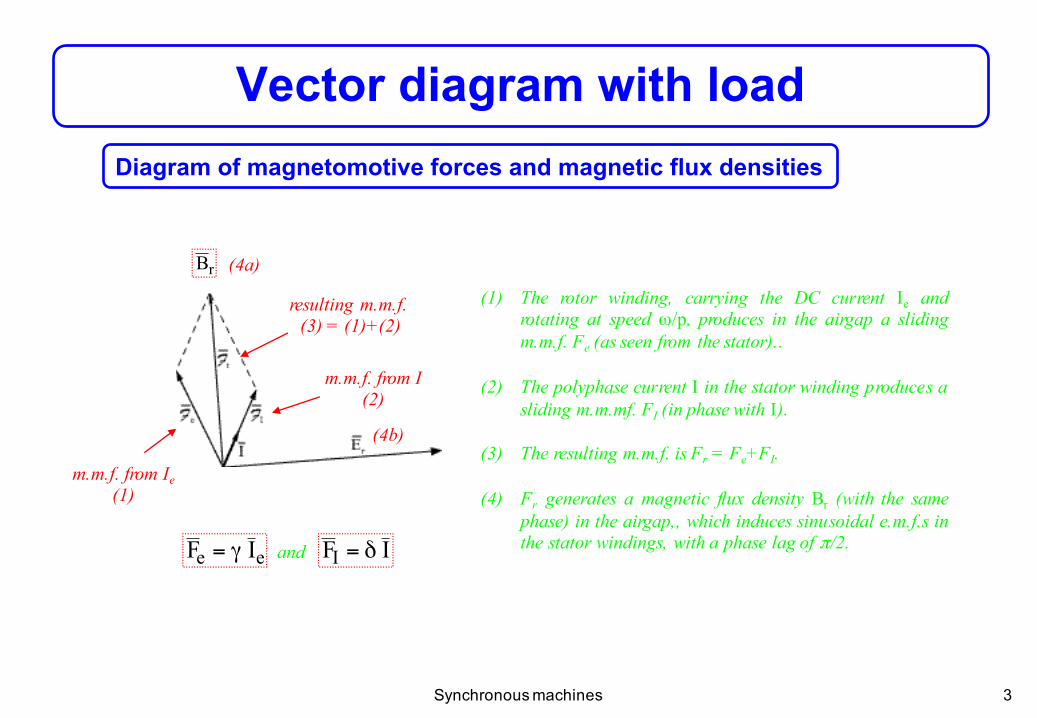
Vector diagram with loadDiagram of magnetomotive forces and magnetic flux densities
resulting m.m.f. (3) = (1)+(2)
m.m.f. from Ie(1)
m.m.f. from I(2)
(1) The rotor winding, carrying the DC current Ie androtating at speed ω/p, produces in the airgap a slidingm.m.f. Fe (as seen from the stator)..
(2) The polyphase current I in the stator winding produces asliding m.m.mf. FI (in phase with I).
(3) The resulting m.m.f. is Fr = Fe+FI.
(4) Fr generates a magnetic flux density Br (with the samephase) in the airgap,, which induces sinusoidal e.m.f.s inthe stator windings, with a phase lag of π/2.
(4b)
rB (4a)
ee IF γ= IFI δ=and
Synchronous machines
4
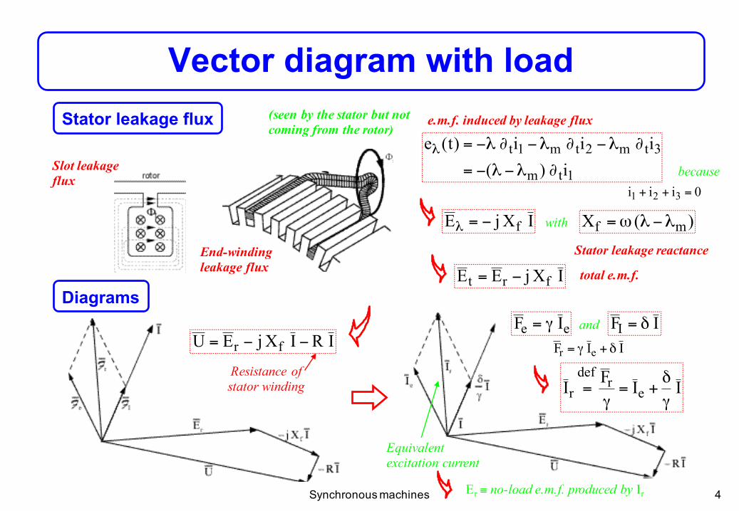
Vector diagram with loadStator leakage flux
1tm
3tm2tm1ti)(
iii)t(e∂λ−λ−=
∂λ−∂λ−∂λ−=λ
IXjE f−=λ )(X mf λ−λω=
Slot leakage flux
End-winding leakage flux IXjEE frt −=
IRIXjEU fr −−=
0iii 321 =++
(seen by the stator but not coming from the rotor)
e.m.f. induced by leakage flux
because
with
Stator leakage reactance
total e.m.f.
Resistance of stator winding
ee IF γ= IFI δ=and
IIF er δ+γ=
IIFI er
defr γ
δ+=
γ=
Equivalent excitation current
Diagrams
Er ≡ no-load e.m.f. produced by IrSynchronous machines

5
‘Which excitation current Ie should one impose in the synchronousmachine to reach the functioning point corresponding to a givenvoltage U and current I in the stator, with a phase shift of ϕbetween U and I?’
Potier diagram
IXjIRUE fr ++=
(1)(0)
(2)(3)
(4)
(5)
(2)
(3)III re γδ
−=
Er ≡ no-load e.m.f produced by theequivalent current Ir
Synchronous machines

6
Reaction
Demagnetizing reaction Magnetizing reaction
The m.m.f. is smaller than the no-load m.m.f. (Ir < Ie)The m.m.f. is larger thanthe no-load m.m.f. (Ir > Ie)
Inductive behaviour of the load(I lagging behind U)
Capacitive behaviour of the load(I in front of U)
Synchronous machines

7
Zero power factor characteristic
Evolution of the stator voltage U as a function of theexcitation current Ie, for a given rotation speed and statorcurrent, with a zero power factor
⎪⎩
⎪⎨
⎧
π±=ϕ=ϕ
=
=θ
=
)2/(0cosconstanteI
constantevitesseavec)I(fU e
!
Example: ϕ = π/2
IXEU fr −≈
III re γδ
+≈
Synchronous machines
with
speed constant constant

8
Short-circuit characteristic
Evolution of the stator current as a function of the excitationcurrent Ie, for a given rotation speed and with the statorwindings in short-circuit
⎩⎨⎧
=
=θ=
0Uconstantevitesse
avec)I(fI e!
IXjIRE fr +=
IXjIRUE fr ++=
0U =with
rr IE β=
IXE fr ≈
III re γδ
+≈
ef
IX
I
γδ
β+
β≈
Non saturatedmachine
Synchronous machines
with speed constant
9
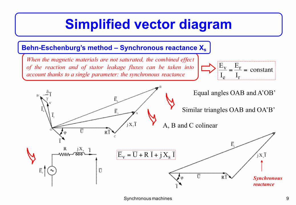
When the magnetic materials are not saturated, the combined effectof the reaction and of stator leakage fluxes can be taken intoaccount thanks to a single parameter: the synchronous reactance
Simplified vector diagramBehn-Eschenburg’s method – Synchronous reactance Xs
constanteIE
IE
r
r
e
v ==
Synchronousreactance
IXjIRUE sv ++=
Synchronous machines
constant
Equal angles OAB and A’OB’
Similar triangles OAB and OA’B’
A, B and C colinear

10
Experimental determination of Xs
Behn-Eschenburg’s method – Synchronous reactance Xs
)I(I)I(EXecc
evs ≈
( ) ccsv IXjRE +=
cc
vs IEXjR =+ sXR <<
0U = ⇒
⇒ with
Approximation when magnetic materialsare saturated!
Synchronous machines
11
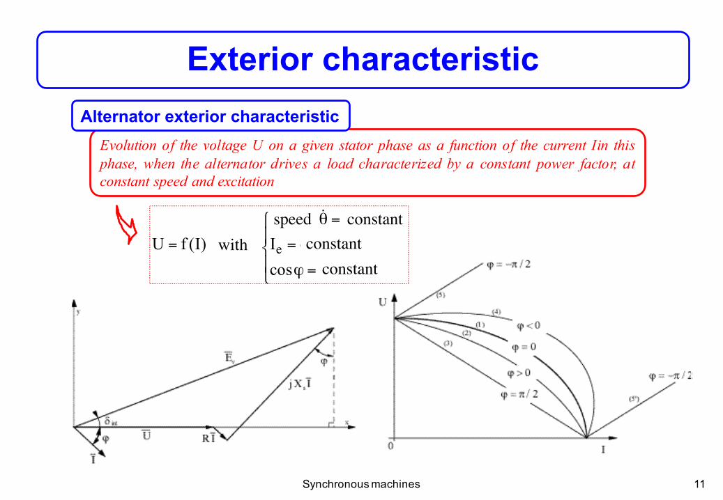
Exterior characteristic
Evolution of the voltage U on a given stator phase as a function of the current Iin thisphase, when the alternator drives a load characterized by a constant power factor, atconstant speed and excitation
⎪⎩
⎪⎨
⎧
=ϕ
=
=θ
=
constantecosconstanteI
constantevitesseavec)I(fU e
!
Alternator exterior characteristic
Synchronous machines
with constant
constant constant
speed

12
Economical organization of power production + Stability of thenetwork despite local defects
Network connectionNeed for interconnection of electric power plants
Synchronization of an alternaltor on an ideal (infinitely powerful) AC network
Large number of production units in parallel⇒ constant voltage and frequency
s
vXjRUEI
+−
=
The current should be zero when the connection is made → 4 conditions
1. same pulsation ω (correct rotation speed)2. same amplitudes for Ev and U (adjusting Ie)3. no phase shift between Ev and U4. identical phase ordering (in a 3-phase system)
Daily peak
Daily load
Synchronous machines
13
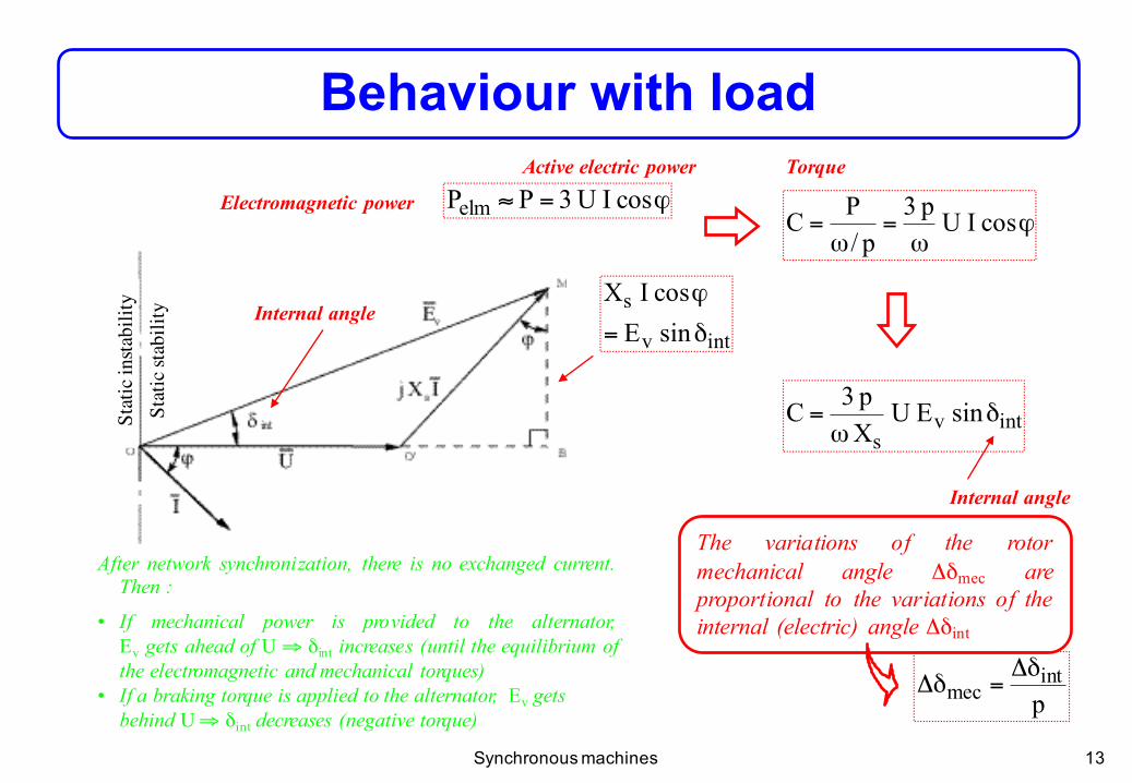
Behaviour with load
ϕ=≈ cosIU3PPelmϕ
ω=
ω= cosIUp3
p/PC
intv
ssinEcosIX
δ=
ϕ
intvs
sinEUXp3C δ
ω=
Internal angle
Electromagnetic power
Torque
The variations of the rotormechanical angle Δδmec areproportional to the variations of theinternal (electric) angle Δδint
After network synchronization, there is no exchanged current.Then :
• If mechanical power is provided to the alternator,Ev gets ahead of U ⇒ δint increases (until the equilibrium ofthe electromagnetic and mechanical torques)
• If a braking torque is applied to the alternator, Ev gets behind U⇒ δint decreases (negative torque)
pint
mecδΔ
=δΔ
Active electric power
Internal angle
Synchronous machines
Stat
ic in
stabi
lity
St
atic
stab
ility
14
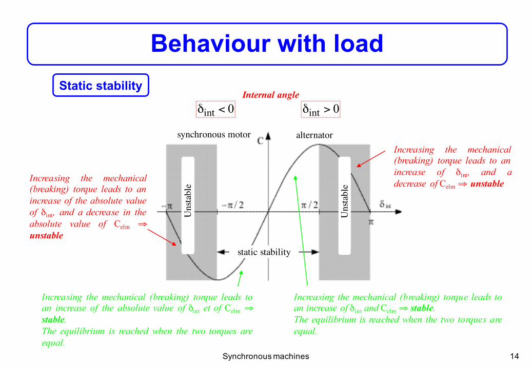
Behaviour with loadStatic stability
0int >δ0int <δ
Increasing the mechanical (breaking) torque leads toan increase of δint and Celm ⇒ stable.The equilibrium is reached when the two torques areequal.
Increasing the mechanical(breaking) torque leads to anincrease of δint, and adecrease of Celm ⇒ unstable
Increasing the mechanical (breaking) torque leads toan increase of the absolute value of δint et of Celm ⇒stable.The equilibrium is reached when the two torques areequal.
Increasing the mechanical(breaking) torque leads to anincrease of the absolute valueof δint, and a decrease in theabsolute value of Celm ⇒unstable
Internal angle
Synchronous machines
Uns
tabl
e
Uns
tabl
e
synchronous motor alternator
static stability
15
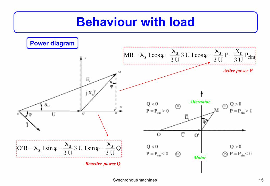
Behaviour with loadPower diagram
elmsss
s PU3XP
U3XcosIU3
U3XcosIXMB ==ϕ=ϕ=
QU3XsinIU3
U3XsinIXB'O ss
s =ϕ=ϕ=
Active power P
Reactive power Q
Alternator
Motor
Synchronous machines

16
V-curves (Mordey curves)Evolution of the stator current I as afunction of the excitation current Ieof a synchronous machine connectedto an ideal network, at constantactive power
Constant active power
Over-excitedmachine
under-excited machine
"V"
Network= inductive loadMachine = capacitif system
ϕ > 0
ϕ > 0 ...
Synchronous machines
static stability limit