om top-z book 1 2189535 01 1703 9lgs · • The pump may be carried only by th e motor/pump housing...
28
Wilo-TOP-Z Pioneering for You de Einbau- und Betriebsanleitung en Installation and operating instructions fr Notice de montage et de mise en service nl Inbouw- en bedieningsvoorschriften es Instrucciones de instalación y funcionamiento it Istruzioni di montaggio, uso e manutenzione pt Manual de Instalação e funcionamento el Οδηγίες εγκατάστασης και λειτουργίας tr Montaj ve kullanma kılavuzu 2 189 535-Ed.01 / 2017-03-Wilo
Transcript of om top-z book 1 2189535 01 1703 9lgs · • The pump may be carried only by th e motor/pump housing...

Wilo-TOP-Z
Pioneering for You
de Einbau- und Betriebsanleitungen Installation and operating instructionsfr Notice de montage et de mise en servicenl Inbouw- en bedieningsvoorschriftenes Instrucciones de instalación y funcionamiento
it Istruzioni di montaggio, uso e manutenzionept Manual de Instalação e funcionamentoel Οδηγίεςεγκατάστασηςκαιλειτουργίαςtr Montajvekullanmakılavuzu
2 189 535-Ed.01 / 2017-03-Wilo
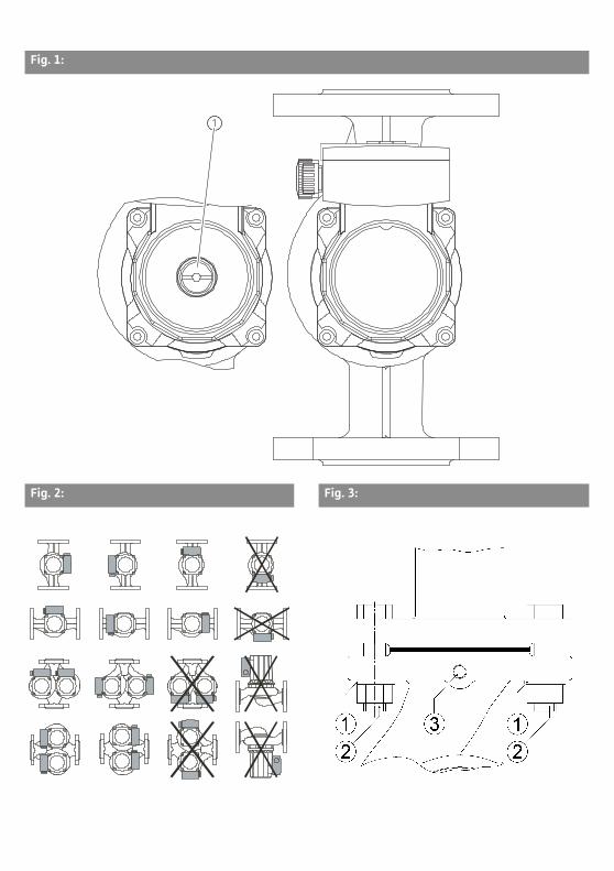
Fig. 1:
Fig. 2: Fig. 3:
Fig. 4: 1~
Fig. 4: 3~
max.
med.min.
LNC1C2C31015(WSK)
1-230V
L1L2L31015(WSK)
400V
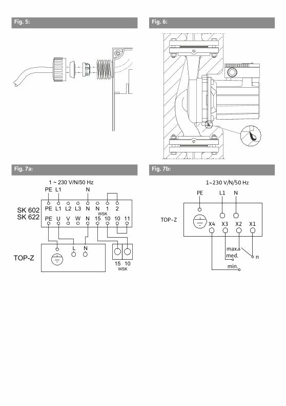
Fig. 5: Fig. 6:
Fig. 7a: Fig. 7b:
1 ~ 230 V/N/50 Hz
PE
PE
PESK 602SK 622
L2L1
L1
VU
L3 N
N
N 1 2WSK
WSK
W N 15 10 10 11
L N
15 10TOP-Z med.
min.
max.n
X4 X3 X2 X1TOP-Z
L1PE
1~230 V/N/50 Hz
N
Installation and operating instructions Wilo-TOP-Z 23
English
Installation and operating instructions1 General information
About this documentThe language of the original operating instructions is German. All other lan-guages of these instructions are translations of the original operating instruc-tions.These installation and operating instructions are an integral part of the product. They must be kept readily available at the place where the product is installed. Strict adherence to these instructions is a precondition for properly using and correctly operating the product. These installation and operating instructions correspond to the relevant version of the product and the underlying safety standards valid at the time of going to print.EC-Declaration of conformity:A copy of the EC-Declaration of conformity is a component of these installation and operating instructions. If a technical modification is made without our agreement to the designs named in the declaration or the declarations made in the installation and operating instructions on product/personnel safety are not observed, this declaration loses its validity.
2 SafetyThese installation and operating instructions contain basic information which must be adhered to during installation, operation and maintenance. For this rea-son, these installation and operating instructions must, without fail, be read by the service technician and the responsible qualified personnel/operator before installation and commissioning.It is not only the general safety instructions listed under the main point “safety” that must be adhered to but also the special safety instructions that are marked by danger symbols and included under the following main points.
2.1 Symbols and signal words in the installation and operating instructions
Symbols:
General danger symbol
Danger due to electrical voltage
USEFUL INFORMATION:
Signal words:
DANGER!
Acutely dangerous situation.
Non-observance results in death or the most serious of injuries.
English
24 WILO SE 03/2017
WARNING!
The user can suffer (serious) injuries. ‘Warning’ implies that (serious) injury
to persons is probable if this information is disregarded.
CAUTION!
There is a risk of damaging the product/unit. ‘Caution’ implies that damage
to the product is likely if this information is disregarded.
NOTICE: Useful information on handling the product. It draws attention to pos-
sible problems.
Information that appears directly on the product, such as
• direction of rotation arrow, direction of flow symbol
• identification for connections
• rating plate
• warning sticker
must be strictly complied with and ensured readable.
2.2 Personnel qualifications
The installation, operating and maintenance personnel must have the appropri-
ate qualifications for this work. Area of responsibility, terms of reference and
monitoring of the personnel are to be ensured by the operator. If the personnel
are not in possession of the necessary knowledge, they are to be trained and
instructed. This can be carried out, if necessary, by the product manufacturer at
the request of the operator.
2.3 Danger in not observing the safety instructions
Non-observance of the safety instructions can result in the risk of injury to per-
sons and damage to the environment and the product/unit. Non-observance of
the safety instructions leads to loss of any claims to damages.
In particular, non-observance can, for example, result in the following risks:
• danger to persons due to electrical, mechanical and bacteriological factors,
• damage to the environment due to leakage of hazardous materials,
• material damage,
• failure of important product/unit functions,
• failure of required maintenance and repair procedures.
2.4 Safety consciousness on the job
The safety instructions included in these installation and operating instructions,
the existing national regulations for accident prevention together with any inter-
nal working, operating and safety regulations of the operator are to be followed.
Installation and operating instructions Wilo-TOP-Z 25
English
2.5 Safety instructions for the operator
This device can be used by children from 8 years of age as well as people with reduced physical, sensory or mental capacities or lack of experience and knowl-edge if they are supervised or instructed in the safe use of the device and they understand the dangers that can occur. Children are not allowed to play with the device. Cleaning and user maintenance is not allowed to be carried out by chil-dren without supervision.
• If hot or cold components on the product/unit lead to hazards, local measures must be taken to prevent them from being touched.
• Guards for moving components (such as the coupling) must not be removed whilst the product is in operation.
• Leakages of hazardous fluids (e.g. explosive, toxic or hot) must be removed so that no danger occurs to persons or the environment. National statutory provi-sions are to be complied with.
• Highly flammable materials should always to be kept at a safe distance from the product.
• Danger from electrical current must be eliminated. Local directives or general directives (e.g. IEC, VDE etc.) and instructions from local energy supply compa-nies must be adhered to.
2.6 Safety instructions for installation and maintenance work
The operator must ensure that all installation and maintenance work is carried out by authorised and qualified personnel who have sufficiently familiarised themselves with the installation and operating instructions by studying them in detail.Work on the product/unit must only be carried out when at a standstill. It is mandatory that the procedure described in the installation and operating instructions for shutting down the product/unit be complied with.Immediately upon completing work, all safety and protective devices must be put back in position and/or recommissioned.
2.7 Unauthorised modification and manufacture of spare parts
Unauthorised modification and manufacture of spare parts will impair the safety of the product/personnel and make void the manufacturer’s declarations regarding safety.Modifications to the product are only permissible after consultation with the manufacturer. Original spare parts and accessories authorised by the manufac-turer ensure safety. The use of other parts will absolve the manufacturer of lia-bility for ensuing consequences.
2.8 Improper use
The operational reliability of the supplied product is only guaranteed when used properly in accordance with sections 4 and 5 of the installation and operating instructions. The limit values must on no account fall below or exceed those val-ues specified in the catalogue/data sheet.
English
26 WILO SE 03/2017
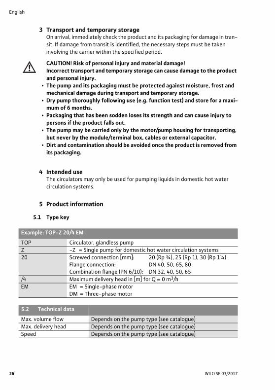
3 Transport and temporary storageOn arrival, immediately check the product and its packaging for damage in tran-
sit. If damage from transit is identified, the necessary steps must be taken
involving the carrier within the specified period.
CAUTION! Risk of personal injury and material damage!
Incorrect transport and temporary storage can cause damage to the product
and personal injury.
• The pump and its packaging must be protected against moisture, frost and
mechanical damage during transport and temporary storage.
• Dry pump thoroughly following use (e.g. function test) and store for a maxi-
mum of 6 months.
• Packaging that has been sodden loses its strength and can cause injury to
persons if the product falls out.
• The pump may be carried only by the motor/pump housing for transporting,
but never by the module/terminal box, cables or external capacitor.
• Dirt and contamination should be avoided once the product is removed from
its packaging.
4 Intended useThe circulators may only be used for pumping liquids in domestic hot water
circulation systems.
5 Product information
5.1 Type key
Example: TOP-Z 20/4 EM
TOP Circulator, glandless pump
Z -Z = Single pump for domestic hot water circulation systems
20 Screwed connection [mm]: 20 (Rp ¾), 25 (Rp 1), 30 (Rp 1¼)Flange connection: DN 40, 50, 65, 80Combination flange (PN 6/10): DN 32, 40, 50, 65
/4 Maximum delivery head in [m] for Q = 0 m3/h
EM EM = Single-phase motorDM = Three-phase motor
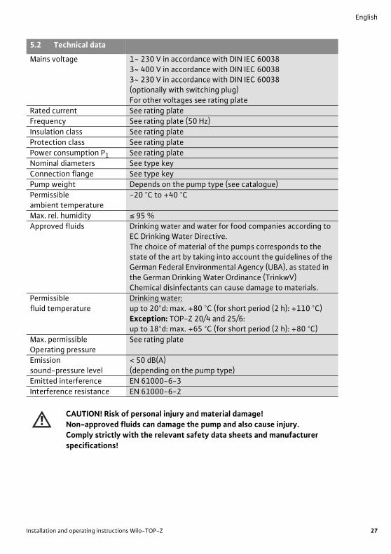
5.2 Technical data
Max. volume flow Depends on the pump type (see catalogue)
Max. delivery head Depends on the pump type (see catalogue)
Speed Depends on the pump type (see catalogue)
Installation and operating instructions Wilo-TOP-Z 27
English
CAUTION! Risk of personal injury and material damage!
Non-approved fluids can damage the pump and also cause injury.
Comply strictly with the relevant safety data sheets and manufacturer
specifications!
Mains voltage 1~ 230 V in accordance with DIN IEC 600383~ 400 V in accordance with DIN IEC 600383~ 230 V in accordance with DIN IEC 60038 (optionally with switching plug)For other voltages see rating plate
Rated current See rating plate
Frequency See rating plate (50 Hz)
Insulation class See rating plate
Protection class See rating plate
Power consumption P1 See rating plate
Nominal diameters See type key
Connection flange See type key
Pump weight Depends on the pump type (see catalogue)
Permissible ambient temperature
-20 °C to +40 °C
Max. rel. humidity ≤ 95 %
Approved fluids Drinking water and water for food companies according to EC Drinking Water Directive.The choice of material of the pumps corresponds to the state of the art by taking into account the guidelines of the German Federal Environmental Agency (UBA), as stated in the German Drinking Water Ordinance (TrinkwV) Chemical disinfectants can cause damage to materials.
Permissible fluid temperature
Drinking water:up to 20°d: max. +80 °C (for short period (2 h): +110 °C)Exception: TOP-Z 20/4 and 25/6:up to 18°d: max. +65 °C (for short period (2 h): +80 °C)
Max. permissible Operating pressure
See rating plate
Emissionsound-pressure level
< 50 dB(A)(depending on the pump type)
Emitted interference EN 61000-6-3
Interference resistance EN 61000-6-2
5.2 Technical data
English
28 WILO SE 03/2017
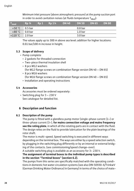
Minimum inlet pressure (above atmospheric pressure) at the pump suction port
in order to avoid cavitation noises (at fluids temperature TMed):
The values apply up to 300 m above sea level; addition for higher locations:
0.01 bar/100 m increase in height.
5.3 Scope of delivery
• Pump complete
• 2 gaskets for threaded connection
• Two-piece thermal insulation shell
• 8 pcs M12 washers
(for M12 flange screws on combination flange version DN 40 – DN 65)
• 8 pcs M16 washers
(for M16 flange screws on combination flange version DN 40 – DN 65)
• Installation and operating instructions
5.4 Accessories
Accessories must be ordered separately:
• Switching plug for 3 ~ 230 V
See catalogue for detailed list.
6 Description and function
6.1 Description of the pump
The pump is fitted with a glandless pump motor (single-phase current (1~) or three-phase current (3~), for mains connection voltage and mains frequency see the rating plate, in which all the rotating parts are in contact with the fluid. The design relies on the fluid to provide lubrication for the plain bearings of the rotor shaft.The motor is multi-speed. Speed switching is executed in different ways depending on the terminal box. The ways are either by a speed selection switch, by plugging in the switching plug differently or by an internal or external bridg-ing of the contacts. (see commissioning/speed change-over). A suitable switching plug is available as an accessory for 3~ 230 V.The assignment of terminal boxes to the individual pump types is described in the section “Terminal boxes” (section 6.2).The pumps from this series are specifically matched with the operating condi-tions in domestic hot water circulation systems (see also DIN 50930-6/TrinkwV (German Drinking Water Ordinance) in Germany) in terms of the choice of mate-
Tmed Rp ¾ Rp 1 Rp 1¼ DN 40 DN 50 DN 65 DN 80
+50 °C 0.5 bar 0.8 bar
+80 °C 0.8 bar 1.0 bar
+110 °C 2.0 bar 3.0 bar
Installation and operating instructions Wilo-TOP-Z 29
English
rial (pump housing made from red brass) and design conformity with the rele-vant regulations (TrinkwV., ACS, WRAS, W3d, guidelines for creating potable water installations). If pumps of the series Wilo-TOP-Z in EN-GJL (pump housing of grey cast iron) are used in domestic hot water circulation systems, the national regulations and guidelines should be complied with as necessary.
6.2 Terminal boxes
There are seven terminal boxes (Fig. 4) for all pump types, which are assigned,
as per table 1, to the pump types:
Table 1: Assignment of terminal box types to pump types (see also Fig. 4)
The fittings for the terminal boxes can be found in Table 2:
Table 2: Fitting of terminal boxes
1) The light indicator signals are carried by a common fibre optic cable to the cover, so that the signals are visible from outside.
2) When mains voltage is present, the lamp lights up green.
• The direction of rotation signal lamp lights up green when mains voltage is
present and the direction of rotation is correct; if the direction of rotation is
incorrect, the control lamp goes out (see the section “Commissioning”).
Mains max. power consumption P1 Terminal box type
connection (see rating plate data) TOP-Z
1~ 95 W ≤ P1max ≤ 205 W 1/2
295 W ≤ P1max ≤ 345 W 3/4/5
3~ 95 W ≤ P1max ≤ 215 W 6
305 W ≤ P1max ≤ 1445 W 7
Terminal box Direction of rotation signal lamp Variable speed control
type (Fig. 4, item 1) (Fig. 4, item 3)
1 - Speed selection switch, 3-step
2 - Internal or external,Bridging of contacts“x1-x2” or “x1-x3” or “x1-x4”
3 - Speed selection switch, 3-step
4 - Internal or external,Bridging of contacts“x1-x2” or “x1-x3” or “x1-x4”
5 - 2) Switching plug, 2-step
6 X (internal) Switching plug, 3-step
7 X 1) Switching plug, 3-step
English
30 WILO SE 03/2017
7 Installation and electrical connection
DANGER! Risk of fatal injury!
Incorrect installation and improper electrical connections can be life-
threatening. Danger from electrical current must be eliminated.
• The installation and electrical connection may only be carried out by
qualified personnel in accordance with the applicable regulations!
• Adhere to accident prevention regulations!
• Comply with the regulations of the local energy supply company!
Pumps with pre-assembled cable:
• Never pull on the pump cable.
• Do not bend the cable.
• Do not place objects on the cable.
7.1 Installation
WARNING! Risk of injury.
Incorrect installation can result in personal injury.
• There is a crushing hazard.
• There is a risk of injury due to sharp edges/burrs. Wear appropriate
protective clothing (e.g. safety gloves)!
• There is a risk of injury caused by the pump/motor falling. Prevent the
pump/motor from falling, if required, by using suitable lifting gear.
CAUTION! Risk of material damage!
Incorrect installation can result in material damage.
• Only use qualified personnel for installation work!
• Observe national and regional regulations!
• When the pump needs to be transported, it may be carried only by the
motor/pump housing. Not by the module/terminal box!
• Installation within a building:
• Install the pump in a dry, well-ventilated room. Ambient temperatures
below -20 °C are not permitted.
• Installation outside a building (outdoor installation):
• Install the pump in a chamber (e.g. light well, ring chamber) with cover or in
a cupboard/housing as weather protection. Ambient temperatures
below -20 °C are not permitted.
• Avoid exposure of the pump to direct sunlight.
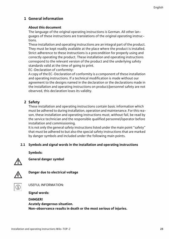
• Protect the pump so that the condensation drain grooves remain free from
contaminants (Fig. 6).
• Protect the pump against rain. Dripping water from above is permitted pro-
vided that the electrical connection has been established in accordance with
the installation and operating instructions and properly sealed.
Installation and operating instructions Wilo-TOP-Z 31
English
CAUTION! Risk of material damage!
Provide adequate ventilation/heating in situations where the permitted
ambient temperature is exceeded or fallen short of.
• Carry out all welding and soldering work prior to the installation of the pump.
CAUTION! Risk of material damage!
Contamination from the pipe system can destroy the pump during operation.
Before installing the pump, flush the pipe system.
• Provide shut-off devices upstream and downstream of the pump.
• Attach piping to the floor, ceiling or wall using appropriate fittings so that the
pump does not bear the weight of the piping.
• When installing in the feed of open systems, the safety supply must branch off
upstream of the pump (DIN EN 12828).
• If necessary remove the two half shells of the thermal insulation before install-
ing the single pump.
• Install the pump at an easily accessible location to allow it to be easily checked
or replaced at a later time.
• Precautions during installation:
• The pump shaft should be installed free from stress and in a horizontal posi-
tion (see installation positions according to Fig. 2). The motor terminal box
must not point downwards. If necessary, slacken the internal hexagon head
screws and rotate the motor housing (see section 9).
• The direction of flow of the fluid must correspond to the flow direction sym-
bol on the pump housing or the pump flange.
7.1.1 Installation of a threaded pipe union pump
• Install appropriate threaded pipe unions before installing the pump.
• Use the supplied flat gaskets between the suction/pressure ports and threaded
pipe unions when installing the pump.
• Screw the union nuts onto the thread of the suction/discharge port and tighten
with a suitable open-end wrench or pipe wrench.
CAUTION! Risk of material damage!
When tightening the pipe unions, keep the pump in position by gripping the
motor. Not the module/terminal box!
• Check the threaded pipe unions for impermeability.
• Single pump:
Fit the two half-shells of the thermal insulation before commissioning and push
them together so that the guide pins engage in the opposing holes.
English
32 WILO SE 03/2017
7.1.2 Installation of a flange-end pump
Assembly of pumps with a combination flange PN 6/10
(Flange-end pumps DN 40 to DN 65 inclusive)
WARNING! Risk of personal injury and material damage!
The flange connection can be damaged and develop leaks if the pump is not
installed correctly. There is a risk of injury and material damage due to hot
fluid escaping.
• Never interconnect two combination flanges!
• Pumps with combination flanges are not permitted for operating pressures
PN 16.
• The use of securing elements (e.g. spring lock washers) can result in leakages
at the flange connection. They are therefore not permitted. The washers
supplied (Fig. 3, item 1) must be inserted between screw heads/nut heads
and the combination flange.
• The permissible tightening torques listed in the table below must not be
exceeded, even if screws of higher strength (≥ 4.6) are used, since splinter-
ing may otherwise occur at the edges of the long holes. This may cause the
screws to lose their prestress and leakage can occur in the flange connection.
• Use screws of sufficient length. The screw thread must project by at least
one pitch of screw thread from the screw nut (Fig. 3, item 2).
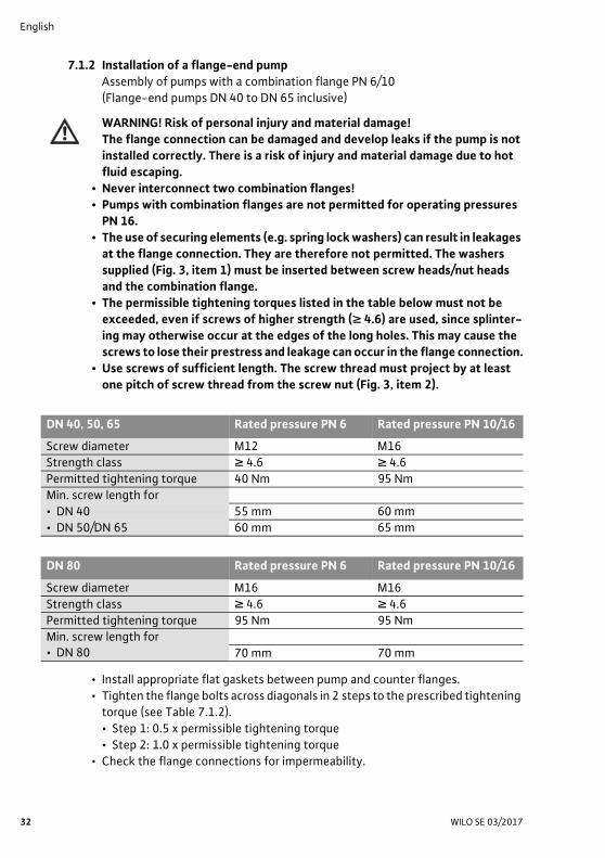
• Install appropriate flat gaskets between pump and counter flanges.
• Tighten the flange bolts across diagonals in 2 steps to the prescribed tightening
torque (see Table 7.1.2).
• Step 1: 0.5 x permissible tightening torque
• Step 2: 1.0 x permissible tightening torque
• Check the flange connections for impermeability.
DN 40, 50, 65 Rated pressure PN 6 Rated pressure PN 10/16
Screw diameter M12 M16
Strength class ≥ 4.6 ≥ 4.6
Permitted tightening torque 40 Nm 95 Nm
Min. screw length for
• DN 40 55 mm 60 mm
• DN 50/DN 65 60 mm 65 mm
DN 80 Rated pressure PN 6 Rated pressure PN 10/16
Screw diameter M16 M16
Strength class ≥ 4.6 ≥ 4.6
Permitted tightening torque 95 Nm 95 Nm
Min. screw length for• DN 80 70 mm 70 mm
Installation and operating instructions Wilo-TOP-Z 33
English
• Single pump:
Fit the two half-shells of the thermal insulation before commissioning and push
them together so that the guide pins engage in the opposing holes.
7.2 Electrical connection
DANGER! Risk of fatal injury!
Improper electrical connections can lead to fatal electric shock.
• Only allow the electrical connection and all associated activities to be carried
out by an electrician approved by the local power supply company and in
accordance with the local applicable regulations.
• Before working on the pump, all poles of the supply voltage must be discon-
nected. Due to the dangerous residual contact voltage (capacitors), no work
may be commenced on the module until 5 minutes have elapsed (only to 1~
version). Check whether all connections (including potential-free contacts)
are voltage-free.
• Do not operate the pump if the module/terminal box is damaged.
• If the setting and operating elements on the module/terminal box are
improperly removed, there is a danger of electric shock by touching the elec-
trical components located inside.
CAUTION! Risk of material damage!
An incorrect electrical connection can cause material damage.
If the wrong voltage is applied, the motor can be damaged!
• The current type and voltage of the mains connection must correspond to the
specifications on the rating plate.
• The electrical connection must be established via a fixed connection line
equipped with a connector device or an all-pole switch with a contact opening
width of at least 3 mm.
• Fuse on mains side: 10 A, slow.
• The pumps can also be used without limitation in existing installations with or
without residual-current devices. When dimensioning the residual-current
device, consider the number of pumps connected and their rated motor
currents.
• When pumps are used in systems with water temperatures above 90 °C,
a suitable heat-resistant connection cable must be used.
• All connection cables must be installed so that they do not touch the pipe
and/or the pump or motor housing.
• In order to ensure drip protection and strain relief on the threaded cable
connection (PG 13.5), a cable with an outer diameter of 10 – 12 mm should be
used and mounted as shown in Fig. 5. In addition, the cable near the screwed
connection should be bent into the form of a drip loop, from which any accumu-
lated drip will fall. Unused threaded cable connections should be blanked off
with the sealing plates provided, and screwed up tight.
English
34 WILO SE 03/2017
• Commission pumps only if they are fitted with the correct modular cover. Check
that the cover gasket is correctly seated.
• Earth the pump/installation as per regulations.
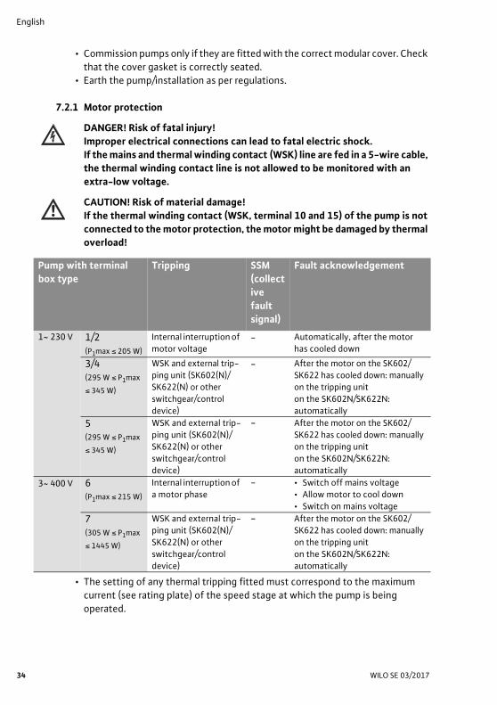
7.2.1 Motor protection
DANGER! Risk of fatal injury!
Improper electrical connections can lead to fatal electric shock.
If the mains and thermal winding contact (WSK) line are fed in a 5-wire cable,
the thermal winding contact line is not allowed to be monitored with an
extra-low voltage.
CAUTION! Risk of material damage!
If the thermal winding contact (WSK, terminal 10 and 15) of the pump is not
connected to the motor protection, the motor might be damaged by thermal
overload!
• The setting of any thermal tripping fitted must correspond to the maximum
current (see rating plate) of the speed stage at which the pump is being
operated.
Pump with terminal
box type
Tripping SSM
(collect
ive
fault
signal)
Fault acknowledgement
1~ 230 V 1/2(P1max ≤ 205 W)
Internal interruption of
motor voltage - Automatically, after the motor
has cooled down
3/4(295 W ≤ P1max
≤ 345 W)
WSK and external trip-
ping unit (SK602(N)/SK622(N) or other
switchgear/control
device)
- After the motor on the SK602/
SK622 has cooled down: manually on the tripping unit
on the SK602N/SK622N:
automatically
5(295 W ≤ P1max
≤ 345 W)
WSK and external trip-
ping unit (SK602(N)/
SK622(N) or other switchgear/control
device)
- After the motor on the SK602/
SK622 has cooled down: manually
on the tripping unit on the SK602N/SK622N:
automatically
3~ 400 V 6(P1max ≤ 215 W)
Internal interruption of a motor phase
- • Switch off mains voltage• Allow motor to cool down
• Switch on mains voltage
7(305 W ≤ P1max
≤ 1445 W)
WSK and external trip-ping unit (SK602(N)/
SK622(N) or other
switchgear/control device)
- After the motor on the SK602/SK622 has cooled down: manually
on the tripping unit
on the SK602N/SK622N: automatically
Installation and operating instructions Wilo-TOP-Z 35
English
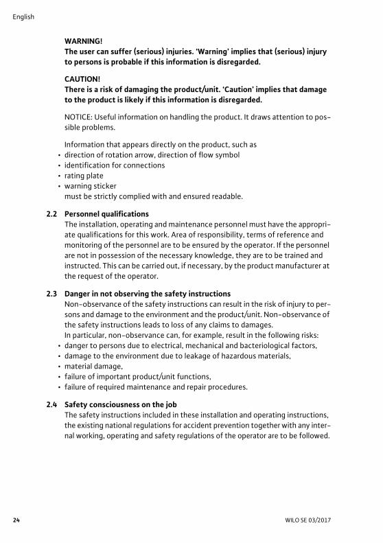
Motor protection tripping units
If Wilo tripping units SK602(N)/SK622(N) are present in existing systems, pumps
with full motor protection (WSK) can be connected to them. Connect the mains
supply and tripping unit (observe the rating plate information) as per the wiring
diagrams (Fig. 7a and Fig. 7b) Fig. 7a:
1~ 230 V: 295 W ≤ P1max ≤ 345 W, with thermal winding contact
7.2.2 Frequency converter operation
The three-phase motors of series TOP-Z can be connected to a frequency con-
verter. When operating with frequency converters, output filters should be used
to reduce noise and to avoid damage due to overvoltages.
For noise reduction, it is recommended that sine filters (LC filters) are used
rather than du/dt filters (RC filters).
The following limit values should be complied with:
• Rate of voltage rise du/dt <500 V/μs
• Overvoltages û < 650 V
The following limit values at the connection terminals of the pump must not be
exceeded:
• Umin = 150 V
• fmin = 30 Hz
At low output frequencies from the frequency converter, the direction of rota-
tion signal lamp at the pump may go out.
8 Commissioning
WARNING! Risk of personal injury and material damage!
Commissioning the pump without the screw plug, including the flat gasket,
is not allowed, since escaping fluid can cause damage!
Prior to commissioning the pump, check that it has been installed and con-
nected correctly.
8.1 Priming and venting
Prime and vent the unit correctly. The pump rotor chamber is vented automat-
ically after a short operating period. Dry running for short periods will not harm
the pump.
WARNING! Risk of personal injury and material damage!
The motor head, the differential pressure screw (Fig. 3, item 3) or the flange
connection/threaded pipe union are not allowed to be undone for the pur-
pose of venting!
• There is a risk of scalding!
Escaping fluid can lead to injuries to persons and material damage.
When the venting screw is opened, hot fluid may escape or shoot out at high
pressure in liquid or vapour form.
English
36 WILO SE 03/2017
• Touching the pump can cause burns!
Depending on the pump or system operating conditions (fluid temperature),
the entire pump can get very hot.
Pumps with venting screws (visible on the motor head; Fig. 1, item 1) can be vented, if required, as follows:
• Switch off the pump.• Close the shut-off device on the pressure side.• Protect electrical parts from any escaping water.• Open venting screw (Fig. 1, item 1) carefully using a suitable tool.
CAUTION! Risk of material damage!
Depending on the operating pressure, the pump may jam when the venting
screw is open.
The necessary inlet pressure must be present at the suction side of the
pump!
• Carefully push back the motor shaft with a screwdriver several times.• After 15 to 30 seconds, screw the venting screw back in.• Switch on the pump.• Open the shut-off device again.
NOTICE! Incomplete venting will lead to noises being produced in the pump and
unit. Repeat the procedure if necessary.
8.2 Direction of rotation monitoring
• Direction of rotation monitoring for 3~: The direction of rotation is displayed, depending on the terminal box, by a light on or in the terminal box (Fig. 4, item 1). If the direction of rotation is correct, the light lights up green. If the direction of rotation is incorrect, the light remains dark. To check the direction of rotation, briefly switch the pump on. If the direc-tion of rotation is incorrect, proceed as follows:• Electrically isolate the pump.• Interchange 2 phases in the terminal box.• Restart the pump.The direction of rotation of the motor must correspond to the direction of rota-tion arrow on the rating plate.
8.2.1 Variable speed control
DANGER! Risk of fatal injury!
When working on the open terminal box, there is a danger of electric shock
from touching the live terminals.
• Disconnect the system from the power and secure it against being switched
on.
• It is not permissible to perform a stage change-over whilst in operation.
• Only qualified personnel may perform a step change-over.
Installation and operating instructions Wilo-TOP-Z 37
English
For 1~ pumps with terminal box type 1, 3 (Fig. 4):
Undo the fastening screws, then remove the terminal box cover, set the inner
3-stage-rotary switch (Fig. 4, item 3) to the symbol of the required speed stage
in the terminal box and properly close the terminal cover.
When the terminal box cover is closed, the speed stage setting can be viewed
through the viewing window.
For 1~ pumps with terminal box type 2, 4 (Fig. 4):
• Speed change-over in the terminal box:
• Undo the fastening screws, then remove the terminal box cover, select the
desired speed stage for the terminal box type 2/4 by changing over the cable
jumpers, then correctly refit the terminal box cover.
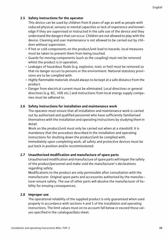
• External speed change-over outside the terminal box (pumps with cable ver-
sion):
• A cable as per wiring diagram Fig. 7b can be connected for externally switch-
ing speed stages. Undo the fastening screws, then remove the terminal box
cover, remove the cable jumpers, feed in the cable through the PG cable gland
and connect it, then correctly refit the terminal box cover. The cable end
should be connected to an external 3-speed selector.
NOTICE! If the cable jumpers are not connected or incorrectly connected, the
pump will not start. Produce connection according to terminal box 2/4 or wiring
diagram Fig. 7b.
For 1~ and 3~ pumps with terminal box type 5, 6, 7 (Fig. 4):
The switching plug in the terminal box can be set to a maximum two or three
stages (depending on the terminal box type).
Undo the fastening screws, then remove the terminal box cover, remove the
switching plug (Fig. 4, item 3) only when the pump is switched off and re-insert
so that the symbol of the required speed stage in the terminal box is shown by
the corresponding marking of the switching plug.
When the terminal box cover is closed, the speed stage setting can be viewed
through the viewing window.
8.3 Decommissioning
The pump must be decommissioned before carrying out maintenance, repair or
dismantling work.
DANGER! Risk of fatal injury!
There is a risk of fatal injury from electric shock when working on electrical
devices.
• Have work on the electrical part of the pump carried out strictly only by a
qualified electrician.
English
38 WILO SE 03/2017
• Before starting any maintenance and repair work, disconnect the pump from
the power supply, and make sure it cannot be switched back on by unauthor-
ised persons.
WARNING! Risk of burn!
Depending on the pump or system operating conditions (fluid temperature),
the entire pump can get very hot. Touching the pump can cause burns.
Allow the system and pump to cool to room temperature.
9 MaintenanceBefore carrying out maintenance / cleaning and repair work, read sections
“Dismantling/installation of the motor” and “Decommissioning”. The safety
instructions in sections 2.6, 7 and 8 must be followed.
After maintenance and repair work, install and connect the pump as described
in the section “Installation and electrical connection”. Switch on the machine as
described in the “Commissioning” section.
9.1 Dismantling/installation of the motor
WARNING! Risk of injury.
• Touching the pump can cause burns!
Depending on the pump or system operating conditions (fluid temperature),
the entire pump can get very hot.
• At high fluid temperatures and system pressures there is the risk of scalding
from escaping hot fluid.
Before dismantling the motor, close the existing shut-off devices on both
sides of the pump, allow the pump to cool to room temperature, and drain the
isolated branch of the system. If no shut-off devices are fitted, drain the sys-
tem.
• Risk of injury from the motor falling when the fastening screws have been
undone.
Comply with national regulations for accident prevention and also with the
operator’s internal work, company and safety regulations. If necessary, wear
protective clothing and equipment!
• During installation/dismantling of the motor head, the rotor unit can fall out
and injure personnel. Do not hold the motor head with the impeller facing
downward.
The motor does not have to be completely removed from the pump housing if
only the terminal box is to be repositioned. The motor can be rotated to the
desired position whilst still attached to the pump housing (see Fig. 2 for the per-
mitted installation positions).
Installation and operating instructions Wilo-TOP-Z 39
English
CAUTION! Risk of material damage!
If for maintenance or repair work the motor head is detached from the pump
housing, the O-ring located between the motor head and pump housing must
be replaced with a new one. Care must be taken to position the O-ring cor-
rectly when installing the motor head.
• To release the motor, undo the 4 internal hexagon head screws.
CAUTION! Risk of material damage!
Do not damage the O-ring located between the motor head and the pump
housing. The O-ring must lie in the angled end of the bearing plate that faces
the impeller, and must not be twisted.
• After the installation, tighten the 4 internal hexagon head screws again
crosswise.
• For the commissioning of the pump, see section 8.
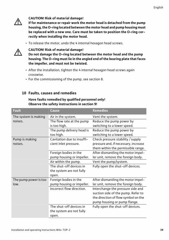
10 Faults, causes and remedies
Have faults remedied by qualified personnel only!
Observe the safety instructions in section 9!
Fault Cause Remedies
The system is making noises.
Air in the system. Vent the system.
The flow rate at the pump is too high.
Reduce the pump power by switching to a lower speed.
The pump delivery head is too high.
Reduce the pump power by switching to a lower speed.
Pump is making noises.
Cavitation due to insuffi-cient inlet pressure.
Check pressure stability / supply pressure and, if necessary, increase them within the permissible range.
Foreign bodies in the pump housing or impeller.
After dismantling the motor impel-ler unit, remove the foreign body.
Air within the pump. Vent the pump/system.
The shut-off devices in the system are not fully open.
Fully open the shut-off devices.
The pump power is too low.
Foreign bodies in the pump housing or impeller.
After dismantling the motor impel-ler unit, remove the foreign body.
Incorrect flow direction. Interchange the pressure side and suction side of the pump. Refer to the direction of flow symbol on the pump housing or pump flange.
The shut-off devices in the system are not fully open.
Fully open the shut-off devices.
English
40 WILO SE 03/2017
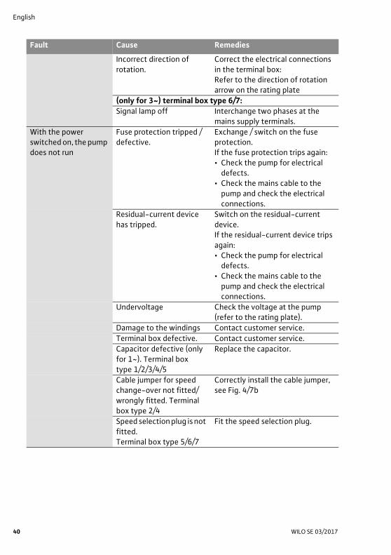
Incorrect direction of rotation.
Correct the electrical connections in the terminal box:Refer to the direction of rotation arrow on the rating plate
(only for 3~) terminal box type 6/7:
Signal lamp off Interchange two phases at the mains supply terminals.
With the power switched on, the pump does not run
Fuse protection tripped / defective.
Exchange / switch on the fuse protection.If the fuse protection trips again:• Check the pump for electrical
defects.• Check the mains cable to the
pump and check the electrical connections.
Residual-current device has tripped.
Switch on the residual-current device.If the residual-current device trips again:• Check the pump for electrical
defects.• Check the mains cable to the
pump and check the electrical connections.
Undervoltage Check the voltage at the pump (refer to the rating plate).
Damage to the windings Contact customer service.
Terminal box defective. Contact customer service.
Capacitor defective (only for 1~). Terminal box type 1/2/3/4/5
Replace the capacitor.
Cable jumper for speed change-over not fitted/wrongly fitted. Terminal box type 2/4
Correctly install the cable jumper, see Fig. 4/7b
Speed selection plug is not fitted.Terminal box type 5/6/7
Fit the speed selection plug.
Fault Cause Remedies
Installation and operating instructions Wilo-TOP-Z 41
English
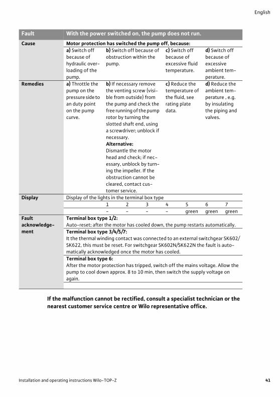
If the malfunction cannot be rectified, consult a specialist technician or the
nearest customer service centre or Wilo representative office.
Fault With the power switched on, the pump does not run.
Cause Motor protection has switched the pump off, because:
a) Switch off
because of
hydraulic over-loading of the
pump.
b) Switch off because of
obstruction within the
pump.
c) Switch off
because of
excessive fluid temperature.
d) Switch off
because of
excessive ambient tem-
perature.
Remedies a) Throttle the pump on the
pressure side to
an duty point on the pump
curve.
b) If necessary remove the venting screw (visi-
ble from outside) from
the pump and check the free running of the pump
rotor by turning the
slotted shaft end, using a screwdriver; unblock if
necessary.
Alternative:Dismantle the motor
head and check; if nec-
essary, unblock by turn-ing the impeller. If the
obstruction cannot be
cleared, contact cus-tomer service.
c) Reduce the temperature of
the fluid, see
rating plate data.
d) Reduce the ambient tem-
perature , e.g.
by insulating the piping and
valves.
Display Display of the lights in the terminal box type
1 2 3 4 5 6 7
- - - - green green green
Fault
acknowledge-ment
Terminal box type 1/2:
Auto-reset; after the motor has cooled down, the pump restarts automatically.
Terminal box type 3/4/5/7:
It the thermal winding contact was connected to an external switchgear SK602/
SK622, this must be reset. For switchgear SK602N/SK622N the fault is auto-matically acknowledged once the motor has cooled.
Terminal box type 6:
After the motor protection has tripped, switch off the mains voltage. Allow the pump to cool down approx. 8 to 10 min, then switch the supply voltage on
again.
English
42 WILO SE 03/2017
11 Spare partsSpare parts may be ordered via local professional technicians and/or Wilo
customer service.
To avoid queries and incorrect orders, all data from the rating plate must be
specified with every order.
12 DisposalProper disposal and recycling of this product prevents damage to the environ-ment and risks to personal health.
1. When disposing of all or part of the product, use public or private disposal companies.
2. For more information on proper disposal, please contact your local council or waste disposal office or the supplier
from which the product was purchased.
NOTICE: The pump must not be disposed of along with household waste!For further information on recycling, visit www.wilo-recycling.com
Subject to change without prior notice!
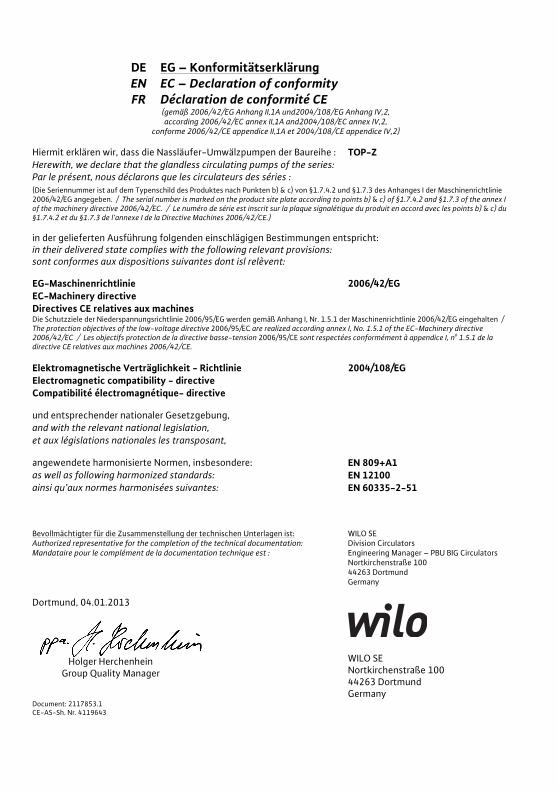
DE EG � Konformitätserklärung EN EC � Declaration of conformity FR Déclaration de conformité CE
(gemäß 2006/42/EG Anhang II,1A und2004/108/EG Anhang IV,2,according 2006/42/EC annex II,1A and2004/108/EC annex IV,2,
conforme 2006/42/CE appendice II,1A et 2004/108/CE appendice IV,2) Hiermit erklären wir, dass die Nassläufer-Umwälzpumpen der Baureihe : TOP-ZHerewith, we declare that the glandless circulating pumps of the series:Par le présent, nous déclarons que les circulateurs des séries : (Die Seriennummer ist auf dem Typenschild des Produktes nach Punkten b) & c) von §1.7.4.2 und §1.7.3 des Anhanges I der Maschinenrichtlinie 2006/42/EG angegeben. / The serial number is marked on the product site plate according to points b) & c) of §1.7.4.2 and §1.7.3 of the annex I of the machinery directive 2006/42/EC. / Le numéro de série est inscrit sur la plaque signalétique du produit en accord avec les points b) & c) du §1.7.4.2 et du §1.7.3 de l�annexe I de la Directive Machines 2006/42/CE.) in der gelieferten Ausführung folgenden einschlägigen Bestimmungen entspricht:in their delivered state complies with the following relevant provisions:sont conformes aux dispositions suivantes dont isl relèvent: EG-Maschinenrichtlinie 2006/42/EG EC-Machinery directive Directives CE relatives aux machines Die Schutzziele der Niederspannungsrichtlinie 2006/95/EG werden gemäß Anhang I, Nr. 1.5.1 der Maschinenrichtlinie 2006/42/EG eingehalten / The protection objectives of the low-voltage directive 2006/95/EC are realized according annex I, No. 1.5.1 of the EC-Machinery directive 2006/42/EC / Les objectifs protection de la directive basse-tension 2006/95/CE sont respectées conformément à appendice I, no 1.5.1 de la directive CE relatives aux machines 2006/42/CE. Elektromagnetische Verträglichkeit - Richtlinie 2004/108/EG Electromagnetic compatibility - directive Compatibilité électromagnétique- directive und entsprechender nationaler Gesetzgebung,and with the relevant national legislation, et aux législations nationales les transposant, angewendete harmonisierte Normen, insbesondere: EN 809+A1 as well as following harmonized standards: EN 12100ainsi qu�aux normes harmonisées suivantes: EN 60335-2-51 Bevollmächtigter für die Zusammenstellung der technischen Unterlagen ist:Authorized representative for the completion of the technical documentation: Mandataire pour le complément de la documentation technique est :
WILO SEDivision Circulators Engineering Manager � PBU BIG Circulators Nortkirchenstraße 100 44263 Dortmund Germany
Dortmund, 04.01.2013
Holger Herchenhein
Group Quality Manager
WILO SE Nortkirchenstraße 100 44263 Dortmund Germany
Document: 2117853.1 CE-AS-Sh. Nr. 4119643
NL IT ESEG-verklaring van overeenstemming Dichiarazione di conformità CE Declaración de conformidad CEHiermede verklaren wij dat dit aggregaat in de geleverde uitvoering voldoet aan de volgende bepalingen:
Con la presente si dichiara che i presenti prodotti sono conformi alle seguenti disposizioni e direttive rilevanti:
Por la presente declaramos la conformidad del producto en su estado de suministro con las disposiciones pertinentes siguientes:
EG-richtlijnen betreffende machines 2006/42/EG Direttiva macchine 2006/42/EG Directiva sobre máquinas 2006/42/EGElektromagnetische compatibiliteit 2004/108/EG Compatibilità elettromagnetica 2004/108/EG Directiva sobre compatibilidad electromagnética 2004/108/EGgebruikte geharmoniseerde normen, in het bijzonder: norme armonizzate applicate, in particolare: normas armonizadas adoptadas, especialmente:zie vorige pagina vedi pagina precedente véase página anterior
PT SV NODeclaração de Conformidade CE CE- försäkran EU-OverensstemmelseserklæringPela presente, declaramos que esta unidade no seu estado original, está conforme os seguintes requisitos:
Härmed förklarar vi att denna maskin i levererat utförande motsvarar följande tillämpliga bestämmelser:
Vi erklærer hermed at denne enheten i utførelse som levert er i overensstemmelse med følgende relevante bestemmelser:
Directivas CEE relativas a máquinas 2006/42/EG EG�Maskindirektiv 2006/42/EG EG�Maskindirektiv 2006/42/EGCompatibilidade electromagnética 2004/108/EG EG�Elektromagnetisk kompatibilitet � riktlinje 2004/108/EG EG�EMV�Elektromagnetisk kompatibilitet 2004/108/EGnormas harmonizadas aplicadas, especialmente: tillämpade harmoniserade normer, i synnerhet: anvendte harmoniserte standarder, særlig:ver página anterior se föregående sida se forrige side
FI DA HUCE-standardinmukaisuusseloste EF-overensstemmelseserklæring EK-megfelel�ségi nyilatkozatIlmoitamme täten, että tämä laite vastaa seuraavia asiaankuuluvia määräyksiä:
Vi erklærer hermed, at denne enhed ved levering overholder følgende relevante bestemmelser:
Ezennel kijelentjük, hogy az berendezés megfelel az alábbi irányelveknek:
EU�konedirektiivit: 2006/42/EG EU�maskindirektiver 2006/42/EG Gépek irányelv: 2006/42/EKSähkömagneettinen soveltuvuus 2004/108/EG Elektromagnetisk kompatibilitet: 2004/108/EG Elektromágneses összeférhet�ség irányelv: 2004/108/EKkäytetyt yhteensovitetut standardit, erityisesti: anvendte harmoniserede standarder, særligt: alkalmazott harmonizált szabványoknak, különösen:katso edellinen sivu. se forrige side lásd az el�z� oldalt
CS PL RUProhlá�ení o shod� ES Deklaracja Zgodno�ci WE ����� �� � ������������ ���������� ������Prohla�ujeme tímto, �e tento agregát v�dodaném provedení odpovídá následujícím p�íslu�ným ustanovením:
Niniejszym deklarujemy z pe�n odpowiedzialnoci, �e dostarczony wyrób jest zgodny z nast�pujcymi dokumentami:
�������� ���������� ��������, ��� �����! �"#�"�� � �"� �$%��� '������� ������������� �����*��� ��#�������� ����������:
Sm�rnice ES pro strojní za�ízení 2006/42/ES dyrektyw� maszynow� WE 2006/42/WE �������� EC � ��������� ����� 2006/42/EGSm�rnice o elektromagnetické kompatibilit� 2004/108/ES dyrektyw� dot. kompatybilno�ci elektromagnetycznej
2004/108/WE�������������� �����!�����" 2004/108/EG
pou�ité harmoniza+ní normy, zejména: stosowanymi normami zharmonizowanymi, a w szczególnoci: ;�'��<������ ��"���������� ������#�� � ��#��, � ��������� :
viz p�edchozí strana patrz poprzednia strona ��. '#�������* ��#���=�
EL TR RO#$%&'( ')**,7;&'(< =(< >> CE Uygunluk Teyid Belgesi EC-Declara?ie de conformitate>?@FJRY[\ ]^_ ^R `{R|]J }Y^] �� }Y^� ^?J �}^��^}�? `}{��R�?� _�}JR`R_\� ^_� }�]@RY�\� �_}^��\_� :
Bu cihaz�n teslim edildi�i �ekliyle a�a��daki standartlara uygun oldu�unu teyid ederiz:
Prin prezenta declar�m c� acest produs a�a cum este livrat, corespunde cu urm�toarele prevederi aplicabile:
@J(QXY< E[ Q\] *(^]_$*]=] 2006/42/E[ AB-Makina Standartlar` 2006/42/EG Directiva CE pentru ma{ini 2006/42/EG|%Y}=7~*]Q_(=\}$ ')*�]=,=(=] E[-2004/108/E[ Elektromanyetik Uyumluluk 2004/108/EG Compatibilitatea electromagnetic� � directiva 2004/108/EG�J}{[RJ_�[�J} �{?�_[R`R_R�[\J} `{]^Y`}, _�_}�^\{}: k�smen kullan�lan standartlar için: standarde armonizate aplicate, îndeosebi:�@�`\ `{R?�R�[\J? �\@��} bkz. bir önceki sayfa vezi pagina precedent�
ET LV LTEÜ vastavusdeklaratsioon EC - atbilst�bas deklar�cija EB atitikties deklaracijaKäesolevaga tõendame, et see toode vastab järgmistele asjakohastele direktiividele:
Ar �o m�s apliecin�m, ka �is izstr�d�jums atbilst sekojo�iem noteikumiem:
�iuo pa�ymima, kad �is gaminys atitinka �ias normas ir direktyvas:
Masinadirektiiv 2006/42/EÜ Ma��nu direkt�va 2006/42/EK Ma�in� direktyv� 2006/42/EBElektromagnetilise ühilduvuse direktiiv 2004/108/EÜ Elektromagn�tisk�s savietojam�bas direkt�va 2004/108/EK Elektromagnetinio suderinamumo direktyv� 2004/108/EBkohaldatud harmoneeritud standardid, eriti: piem�roti harmoniz�ti standarti, tai skait�: pritaikytus vieningus standartus, o b�tent:vt eelmist lk skat�t iepriek��jo lappusi �r. ankstesniame puslapyje
SK SL BGES vyhlásenie o zhode ES � izjava o skladnosti E�-����� �� �� ������������Týmto vyhlasujeme, �e kon�trukcie tejto kon�truk+nej série v dodanom vyhotovení vyhovujú nasledujúcim príslu�ným ustanoveniam:
Izjavljamo, da dobavljene vrste izvedbe te serije ustrezajo slede+im zadevnim dolo+ilom:
�����#�#���, �� '#�����%� ��"���#� �� �������� ����������:
Stroje - smernica 2006/42/ES Direktiva o strojih 2006/42/ES ������� �������� 2006/42/EOElektromagnetická zhoda - smernica 2004/108/ES Direktiva o elektromagnetni zdru�ljivosti 2004/108/ES E������������ ����������� � �������� 2004/108/E�pou�ívané harmonizované normy, najmä: uporabljeni harmonizirani standardi, predvsem: ��#������#��� ������#��:pozri predchádzajúcu stranu glejte prej�njo stran ��. '#������ ��#���=�
MT HR SRDikjarazzjoni ta� konformità KE EZ izjava o sukladnosti EZ izjava o uskla�enostiB'dan il-mezz, niddikjaraw li l-prodotti tas-serje jissodisfaw id-dispo�izzjonijiet relevanti li �ejjin:
Ovim izjavljujemo da vrste konstrukcije serije u isporu+enoj izvedbi odgovaraju sljede�im va�e�im propisima:
Ovim izjavljujemo da vrste konstrukcije serije u isporu+enoj verziji odgovaraju slede�im va�e�im propisima:
Makkinarju - Direttiva 2006/42/KE EZ smjernica o strojevima 2006/42/EZ EZ direktiva za ma�ine 2006/42/EZKompatibbiltà elettromanjetika - Direttiva 2004/108/KE Elektromagnetna kompatibilnost - smjernica 2004/108/EZ Elektromagnetna kompatibilnost - direktiva 2004/108/EZb'mod partikolari: primijenjene harmonizirane norme, posebno: primenjeni harmonizovani standardi, a posebno: ara l-pa�na ta' qabel vidjeti prethodnu stranicu vidi prethodnu stranu
WILO SENortkirchenstraße 10044263 DortmundGermany

WILO SENortkirchenstraße 100D-44263 DortmundGermanyT +49(0)231 4102-0F +49(0)231 [email protected] for You


![Untitled Document [] CS5523 DS317PP2 3 TABLE OF FIGURES CS5521/23 Configured to use on-chip charge pump to supply NBV. 10 Charge Pump Drive Circuit for VD+ = 3 V. 11 Alternate NBV](https://static.fdocument.org/doc/165x107/5acd493c7f8b9a875a8d9f0f/untitled-document-cs5523-ds317pp2-3-table-of-figures-cs552123-configured-to.jpg)