Exercise: Electrical Energy & Capacitance:...
6
University of Alabama Department of Physics and Astronomy PH 106 / LeClair Spring 2008 Exercise: Electrical Energy & Capacitance: Solutions 1. Find the equivalent capacitance of the capacitors in the figure below. + - 12V 3μF 6μF 8μF 8μF4μF Before we start, it is useful to remember that one farad times one volt gives one coulomb: 1[F] · 1[V]=1[C], and that capacitance times voltage gives stored charge: Q = CV . Knowing this now will save some confusion on units later on. For that matter, it is also good to remember that the prefix μ means 10 -6 . In order to find a single equivalent capacitor that could replace all five in the diagram above, we need to look for purely series and parallel combinations that can be replaced by a single capacitor. The uppermost 8 μF and 4 μF capacitors are purely in series, so they can be replaced by a single equivalent we will call C84, as shown below: Using our rule for combining series capacitors, we can find the value of C84 easily: 1 C84 = 1 8 μF + 1 8 μF = ⇒ C84 = 8 3 μF ≈ 2.67 μF Now we have this equivalent capacitance purely in parallel with the second 8 μF capacitor. We can replace C84 and the second 8 μF capacitors with a single equivalent, which we will call C884: Using our addition rule for parallel capacitors, we can find its value:
Transcript of Exercise: Electrical Energy & Capacitance:...

University of AlabamaDepartment of Physics and Astronomy
PH 106 / LeClair Spring 2008
Exercise: Electrical Energy & Capacitance: Solutions1. Find the equivalent capacitance of the capacitors in the figure below.
+ -
12V
3μF6μF
8μF
8μF 4μF
Before we start, it is useful to remember that one farad times one volt gives one coulomb: 1 [F] · 1 [V] = 1 [C], and thatcapacitance times voltage gives stored charge: Q=CV . Knowing this now will save some confusion on units later on. Forthat matter, it is also good to remember that the prefix µ means 10−6.
In order to find a single equivalent capacitor that could replace all five in the diagram above, we need to look for purelyseries and parallel combinations that can be replaced by a single capacitor. The uppermost 8 µF and 4 µF capacitors arepurely in series, so they can be replaced by a single equivalent we will call C84, as shown below:
Using our rule for combining series capacitors, we can find the value of C84 easily:
1
C84=
1
8 µF +1
8 µF
=⇒ C84 =8
3µF ≈ 2.67 µF
Now we have this equivalent capacitance purely in parallel with the second 8 µF capacitor. We can replace C84 and thesecond 8 µF capacitors with a single equivalent, which we will call C884:
Using our addition rule for parallel capacitors, we can find its value:
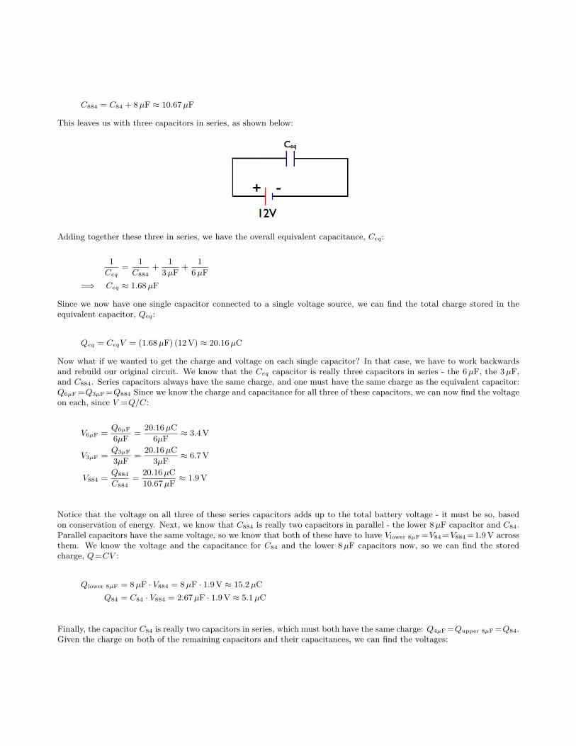
C884 = C84 + 8 µF ≈ 10.67 µF
This leaves us with three capacitors in series, as shown below:
Adding together these three in series, we have the overall equivalent capacitance, Ceq:
1
Ceq=
1
C884+
1
3 µF +1
6 µF=⇒ Ceq ≈ 1.68 µF
Since we now have one single capacitor connected to a single voltage source, we can find the total charge stored in theequivalent capacitor, Qeq:
Qeq = CeqV = (1.68 µF) (12 V) ≈ 20.16 µC
Now what if we wanted to get the charge and voltage on each single capacitor? In that case, we have to work backwardsand rebuild our original circuit. We know that the Ceq capacitor is really three capacitors in series - the 6 µF, the 3 µF,and C884. Series capacitors always have the same charge, and one must have the same charge as the equivalent capacitor:Q6µF =Q3µF =Q884 Since we know the charge and capacitance for all three of these capacitors, we can now find the voltageon each, since V =Q/C:
V6µF =Q6µF
6µF =20.16 µC
6µF ≈ 3.4 V
V3µF =Q3µF
3µF =20.16 µC
3µF ≈ 6.7 V
V884 =Q884
C884=
20.16 µC10.67 µF ≈ 1.9 V
Notice that the voltage on all three of these series capacitors adds up to the total battery voltage - it must be so, basedon conservation of energy. Next, we know that C884 is really two capacitors in parallel - the lower 8 µF capacitor and C84.Parallel capacitors have the same voltage, so we know that both of these have to have Vlower 8µF =V84 =V884 =1.9 V acrossthem. We know the voltage and the capacitance for C84 and the lower 8 µF capacitors now, so we can find the storedcharge, Q=CV :
Qlower 8µF = 8 µF · V884 = 8 µF · 1.9 V ≈ 15.2 µCQ84 = C84 · V884 = 2.67 µF · 1.9 V ≈ 5.1 µC
Finally, the capacitor C84 is really two capacitors in series, which must both have the same charge: Q4µF =Qupper 8µF =Q84.Given the charge on both of the remaining capacitors and their capacitances, we can find the voltages:
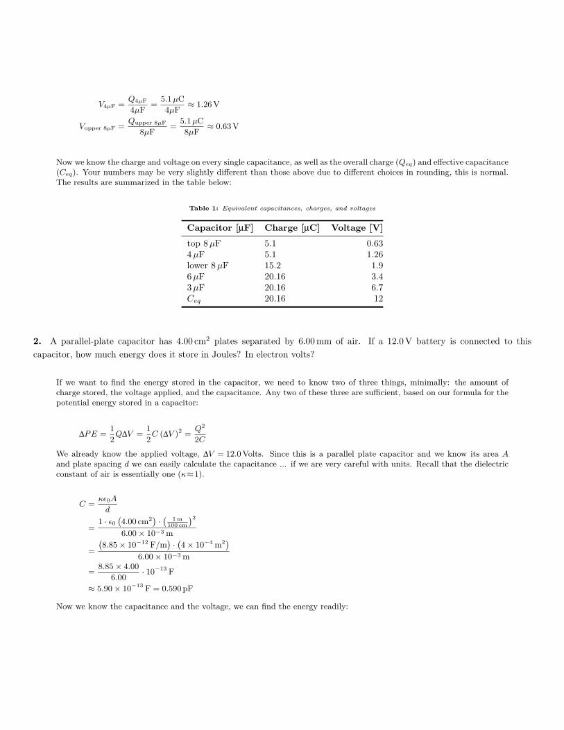
V4µF =Q4µF
4µF =5.1 µC4µF ≈ 1.26 V
Vupper 8µF =Qupper 8µF
8µF =5.1 µC8µF ≈ 0.63 V
Now we know the charge and voltage on every single capacitance, as well as the overall charge (Qeq) and effective capacitance(Ceq). Your numbers may be very slightly different than those above due to different choices in rounding, this is normal.The results are summarized in the table below:
Table 1: Equivalent capacitances, charges, and voltages
Capacitor [µF] Charge [µC] Voltage [V]top 8 µF 5.1 0.634 µF 5.1 1.26lower 8 µF 15.2 1.96 µF 20.16 3.43 µF 20.16 6.7Ceq 20.16 12
2. A parallel-plate capacitor has 4.00 cm2 plates separated by 6.00 mm of air. If a 12.0 V battery is connected to thiscapacitor, how much energy does it store in Joules? In electron volts?
If we want to find the energy stored in the capacitor, we need to know two of three things, minimally: the amount ofcharge stored, the voltage applied, and the capacitance. Any two of these three are sufficient, based on our formula for thepotential energy stored in a capacitor:
∆PE =1
2Q∆V =
1
2C (∆V )2 =
Q2
2C
We already know the applied voltage, ∆V = 12.0 Volts. Since this is a parallel plate capacitor and we know its area Aand plate spacing d we can easily calculate the capacitance ... if we are very careful with units. Recall that the dielectricconstant of air is essentially one (κ≈1).
C =κε0A
d
=1 · ε0
`4.00 cm2
´·
`1 m
100 cm´2
6.00× 10⁻³ m
=
`8.85× 10⁻¹² F/m
´·
`4× 10⁻⁴ m2
´6.00× 10⁻³ m
=8.85× 4.00
6.00· 10−13 F
≈ 5.90× 10⁻¹³ F = 0.590 pF
Now we know the capacitance and the voltage, we can find the energy readily:
∆PE =1
2
`5.90× 10⁻¹³ F
´(12.0 V)2 = 4.25× 10⁻¹¹ F ·V2 = 4.25× 10⁻¹¹ J
=`4.25× 10⁻¹¹ J
´ „1 eV
1.60× 10⁻¹⁹ J
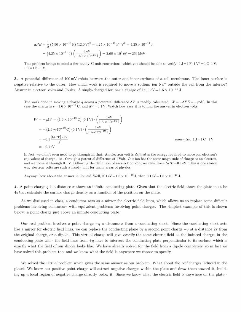
«= 2.66× 10⁸ eV = 266 MeV
This problem brings to mind a few handy SI unit conversions, which you should be able to verify: 1 J=1 F ·1 V2 =1 C ·1 V,1 C=1 F · 1 V.
3. A potential difference of 100 mV exists between the outer and inner surfaces of a cell membrane. The inner surface isnegative relative to the outer. How much work is required to move a sodium ion Na+ outside the cell from the interior?Answer in electron volts and Joules. A singly-charged ion has a charge of 1e, 1 eV=1.6× 10⁻¹⁹ J.
The work done in moving a charge q across a potential difference ∆V is readily calculated: W =−∆PE =−q∆V . In thiscase the charge is e=1.6× 10⁻¹⁹ C, and ∆V =0.1 V. Watch how easy it is to find the answer in electron volts:
W = −q∆V =`1.6× 10⁻¹⁹ C
´(0.1 V) ·
„1 eV
1.6× 10⁻¹⁹ J
«= −
`(((((1.6× 10⁻¹⁹ C
´(0.1 V) ·
„1 eV
(((((1.6× 10⁻¹⁹ J
«= −0.1
[���C ·V] · eV�J
remember: 1 J=1 C · 1 V
= −0.1 eV
In fact, we didn’t even need to go through all that. An electron volt is defined as the energy required to move one electron’sequivalent of charge - 1e - through a potential difference of 1 Volt. Our ion has the same magnitude of charge as an electron,and we move it through 0.1 V. Following the definition of an electron volt, we must have ∆PE =0.1 eV. This is one reasonwhy electron volts are such a handy unit for many areas of physics.
Anyway: how about the answer in Joules? Well, if 1 eV=1.6× 10⁻¹⁹ J, then 0.1 eV=1.6× 10⁻²⁰ J.
4. A point charge q is a distance x above an infinite conducting plate. Given that the electric field above the plate must be4πkeσ, calculate the surface charge density as a function of the position on the plate.
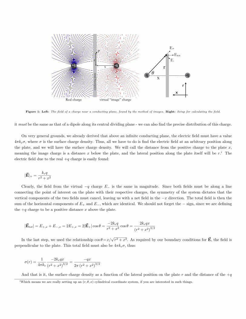
As we discussed in class, a conductor acts as a mirror for electric field lines, which allows us to replace some difficultproblems involving conductors with equivalent problems involving point charges. The simplest example of this is shownbelow: a point charge just above an infinite conducting plate.
Our real problem involves a point charge +q a distance x from a conducting sheet. Since the conducting sheet actslike a mirror for electric field lines, we can replace the conducting plane by a second point charge −q at a distance 2x fromthe original charge, or a dipole. This virtual charge will give exactly the same electric field as the induced charges in theconducting plate will - the field lines from +q have to intersect the conducting plate perpendicular to its surface, which isexactly what the field of our dipole looks like. We have already solved for the field from a dipole completely, so in fact wehave solved this problem too, and we know what the field is anywhere we choose to specify.
We solved the virtual problem which gives the same answer as our problem. What about the real charges induced in theplate? We know our positive point charge will attract negative charges within the plate and draw them toward it, build-ing up a local region of negative charge directly below it. Since we know what the electric field is anywhere on the plate -
+q -q
Real charge virtual “image” chargeco
nduc
ting
plan
e
r
x
P
q -q
r
x
!
r
x
E-
E+
Etot
Figure 1: Left: The field of a charge near a conducting plane, found by the method of images. Right: Setup for calculating the field.
it must be the same as that of a dipole along its central dividing plane - we can also find the precise distribution of this charge.
On very general grounds, we already derived that above an infinite conducting plane, the electric field must have a value4πkeσ, where σ is the surface charge density. Thus, all we have to do is find the electric field at an arbitrary position alongthe plate, and we will have the surface charge density. We will call the distance from the positive charge to the plate x,meaning the image charge is a distance x below the plate, and the lateral position along the plate itself will be r.i Theelectric field due to the real +q charge is easily found:
|~E|+ =keq
r2 + x2
Clearly, the field from the virtual −q charge E− is the same in magnitude. Since both fields must be along a lineconnecting the point of interest on the plate with their respective charges, the symmetry of the system dictates that thevertical components of the two fields must cancel, leaving us with a net field in the −x direction. The total field is then thesum of the horizontal components of E+ and E−, which are identical. We should not forget the − sign, since we are definingthe +q charge to be a positive distance x above the plate.
|~Etot| = E+,x + E−,x = 2E+,x = 2|~E+| cos θ =−2keq
r2 + x2cos θ =
2keqx
(r2 + x2)3/2
In the last step, we used the relationship cos θ=x/√
r2 + x2. As required by our boundary conditions for ~E, the field isperpendicular to the plate. This total field must also be 4πkeσ, thus:
σ(r) =1
4πke
−2keqx
(r2 + x2)3/2=
−qx
2π (r2 + x2)3/2
And that is it, the surface charge density as a function of the lateral position on the plate r and the distance of the +q
iWhich means we are really setting up an (r, θ, x) cylindrical coordinate system, if you are interested in such things.
charge from the plate x. The surface charge density is really only a function of r, as it exists only on the surface of the plate;x is in this case basically a parameter that characterizes the strength of the polarizing +q charge. For an actual dipole, ratherthan a virtual one, the product of the charge and separation (2qx in this case) is known as the dipole moment, and it reallyis a (vector) measure of a dipole’s effective strength.
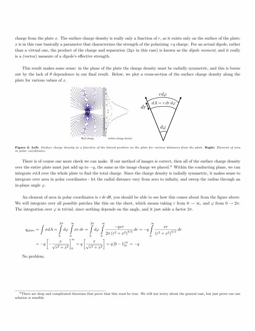
This result makes some sense: in the plane of the plate the charge density must be radially symmetric, and this is borneout by the lack of θ dependence in our final result. Below, we plot a cross-section of the surface charge density along theplate for various values of x.
+q
Real charge
cond
uctin
g pl
ane
surface charge density
d!
rd!
drdA = r dr d!
Figure 2: Left: Surface charge density as a function of the lateral position on the plate for various distances from the plate. Right: Element of areain polar coordinates.
There is of course one more check we can make. If our method of images is correct, then all of the surface charge densityover the entire plate must just add up to −q, the same as the image charge we placed.ii Within the conducting plane, we canintegrate σdA over the whole plate to find the total charge. Since the charge density is radially symmetric, it makes sense tointegrate over area in polar coordinates - let the radial distance vary from zero to infinity, and sweep the radius through anin-plane angle ϕ.
An element of area in polar coordinates is r dr dθ, you should be able to see how this comes about from the figure above.We will integrate over all possible patches like this on the sheet, which means taking r from 0 → ∞, and ϕ from 0 → 2π.The integration over ϕ is trivial, since nothing depends on the angle, and it just adds a factor 2π.
qplate =�
σdA =
2π�
0
dϕ
∞�
0
σr dr =
2π�
0
dϕ
∞�
0
−qxr
2π (r2 + x2)3/2dr = −q
∞�
0
xr
(r2 + x2)3/2dr
= −q
[− x√
r2 + x2
]∞0
= q
[x√
r2 + x2
]= q [0− 1]∞0 = −q
No problem.
iiThere are deep and complicated theorems that prove that this must be true. We will not worry about the general case, but just prove our onesolution is sensible.