


γλώσσες
Σελίδες
Νομικός

UNIVERSITI TUNKU ABDUL RAHMAN
Faculty : Engineering & Science Unit Code : UEEA1243Course : Bachelor of Engineering
(Hons)Unit Title : Circuit Theory
Year/ Semester
: Year 1 Lecturer :
Session : 201101
Tutorial 1
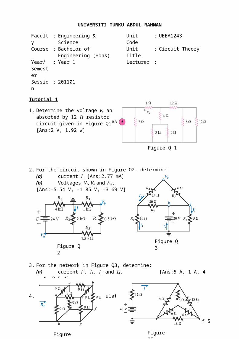
1. Determine the voltage vx and powerabsorbed by 12 resistor for thecircuit given in Figure Q1.[Ans:2 V, 1.92 W]
2. For the circuit shown in Figure Q2, determine:(a) current I. [Ans:2.77 mA](b) Voltages Va, Vb and Vab.[Ans:-5.54 V, -1.85 V, -3.69 V]
3. For the network in Figure Q3, determine:(a) current IS, I1, I3 and I4. [Ans:5 A, 1 A, 4 A, 0.5 A](b) voltage Va and Vb. [Ans:17 V, 20 V]
4. For the Figure Q 4, calculate RT circuit. [Ans:4.2 ]
5. Calculate the current I for the circuit given in the Figure Q5. [Ans:2.67 A]
Page 1 of 3
Figure Q 1
Figure Q 3
Figure Q5Figure Q4
Figure Q 2
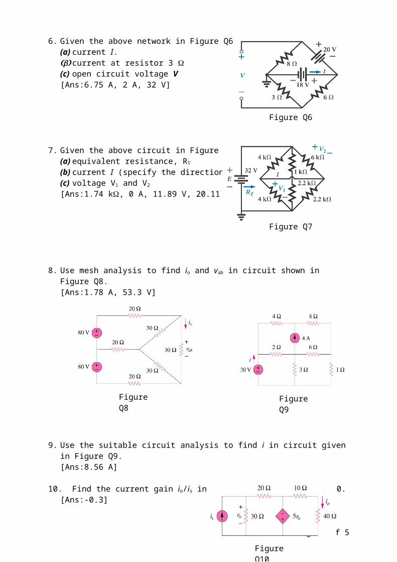
6. Given the above network in Figure Q6, calculate:(a) current I.(b) current at resistor 3 (c) open circuit voltage V[Ans:6.75 A, 2 A, 32 V]
7. Given the above circuit in Figure Q 7, find:(a) equivalent resistance, RT
(b) current I (specify the direction)(c) voltage V1 and V2
[Ans:1.74 k, 0 A, 11.89 V, 20.11 V]
8. Use mesh analysis to find io and vab in circuit shown in Figure Q8.[Ans:1.78 A, 53.3 V]
9. Use the suitable circuit analysis to find i in circuit given in Figure Q9.[Ans:8.56 A]
10. Find the current gain io/is in circuit shown in Figure Q10.[Ans:-0.3]
Page 2 of 3
Figure Q6
Figure Q7
Figure Q8 Figure Q9
Figure Q10
11. Determine v1, v2 and v3 in circuit given in Figure Q11.[Ans:10 V, 4.93 V, 12.27 V]
12. Use the suitable circuit analysis to determine io and vo in circuit given in Figure Q12.[Ans:10.67 A, 33.78 V]
13. Find the voltages across each resistor in the Figure Q13.[Ans: -8 V, 20 V, 12 V]
14. Determine the voltages across each resistive element in the Figure Q14.[Ans:-2.56 V, 4.03 V, -6.59 V]
Page 3 of 3
Figure Q11
Figure Q13 Figure Q14
Figure Q12
Top Related