


γλώσσες
Σελίδες
Νομικός

World Leader in Innovative Power System Testing Solutions
T r a n S f o r m e r D I a g n o S I S
T h e u L T I m a T e T e S T I n g S y S T e m f o r
CPC 100 + CP TD1
2
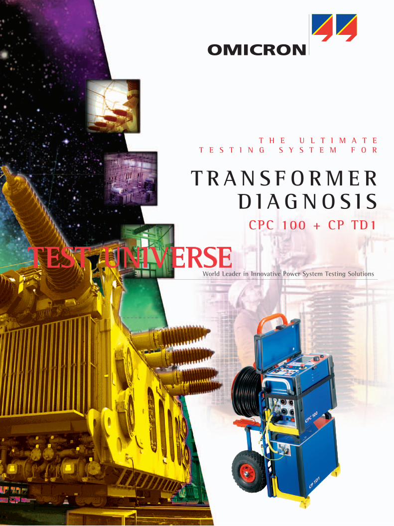
Transformer DiagnosisThe OMICRON Transformer Diagnostic System is a unique test equipment which provides automatic testing of important transformer parameters within one portable system. The test system is comprised of the CPC 100 Multi-function Primary Test System and the CP TD1 Tangent Delta unit. The patented CPC 100 is the main control unit for the test system and the CP-TD1 unit is used for testing of insulation condition. Together, the system is the ideal tool for comprehensive testing of the following parameters of a power transformer:
• Windingresistance
• Turnsratioandexcitationcurrent
• On-loadtapchangercondition
• Leakagereactance
• Insulationcondition(capacitance,tangentdelta,
power factor)
Portable• Easy transportation by a single person - heaviest component:29kg(64lbs)
• Practical handling on and off-site with a custom-built trolleywitheasyandquickbreak-downintosinglecomponents
No Need for multiPle test sets• Onesystemformultipletests• Eliminatestheneedtotrainonmultipledevices• Alltestresultsstoredinonedeviceandinthesame
format
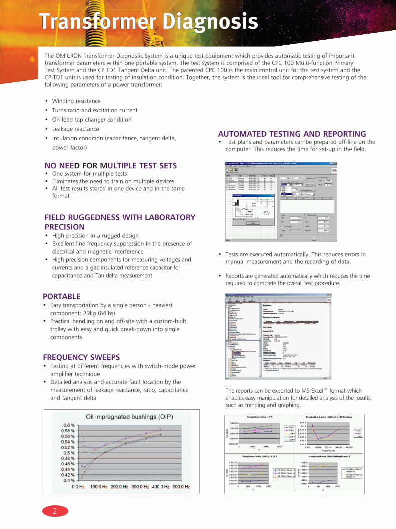
frequeNcy sweePs• Testingatdifferentfrequencieswithswitch-modepower
amplifier technique • Detailedanalysisandaccuratefaultlocationbythemeasurementofleakagereactance,ratio,capacitanceand tangent delta
• Testsareexecutedautomatically.Thisreduceserrorsinmanual measurement and the recording of data.
• Reports are generated automatically which reduces the time required to complete the overall test procedure.
automated testiNg aNd rePortiNg• Testplansandparameterscanbepreparedoff-lineonthe
computer. This reduces the time for set-up in the field.
ThereportscanbeexportedtoMS-Excel™formatwhichenables easy manipulation for detailed analysis of the results such as trending and graphing.
field ruggedNess with laboratory PrecisioN• Highprecisioninaruggeddesign• Excellentline-frequencysuppressioninthepresenceof
electrical and magnetic interference• Highprecisioncomponentsformeasuringvoltagesand
currents and a gas-insulated reference capacitor for capacitance and Tan delta measurement
3
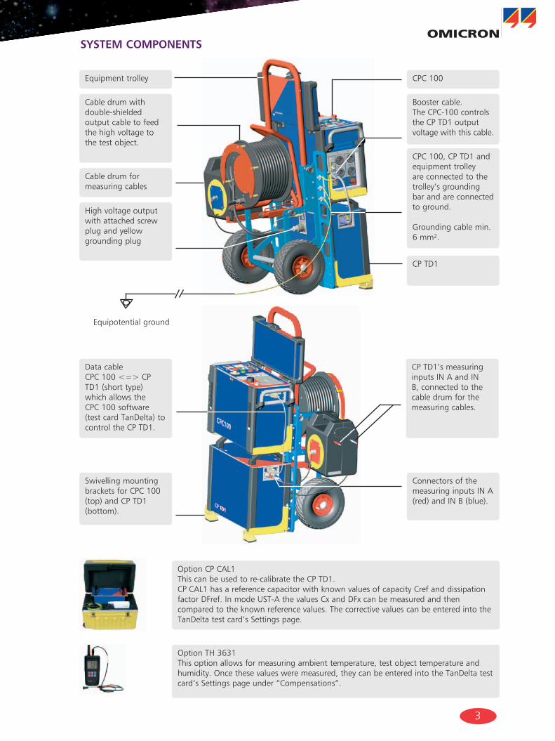
Cable drum with double-shielded output cable to feed the high voltage to the test object.
Equipment trolley CPC 100
Booster cable. The CPC-100 controls the CP TD1 output voltage with this cable.
CPC 100, CP TD1 and equipment trolley are connected to the trolley’s grounding bar and are connected to ground.
Grounding cable min. 6mm2.
Cable drum for measuring cables
Highvoltageoutputwith attached screw plug and yellow grounding plug
Equipotential ground
Data cable CPC 100 <=> CP TD1(shorttype)which allows the CPC 100 software (testcardTanDelta)tocontrol the CP TD1.
Connectors of the measuringinputsINA(red)andINB(blue).
CP TD1’s measuring inputsINAandINB, connected to the cable drum for the measuring cables.
CP TD1
OptionTH3631This option allows for measuring ambient temperature, test object temperature and humidity. Once these values were measured, they can be entered into the TanDelta test card’s Settings page under “Compensations”.
OptionCPCAL1This can be used to re-calibrate the CP TD1. CPCAL1hasareferencecapacitorwithknownvaluesofcapacityCrefanddissipationfactorDFref.InmodeUST-AthevaluesCxandDFxcanbemeasuredandthencomparedtotheknownreferencevalues.ThecorrectivevaluescanbeenteredintotheTanDelta test card’s Settings page.
Swivelling mounting bracketsforCPC100(top)andCPTD1(bottom).
system comPoNeNts
4
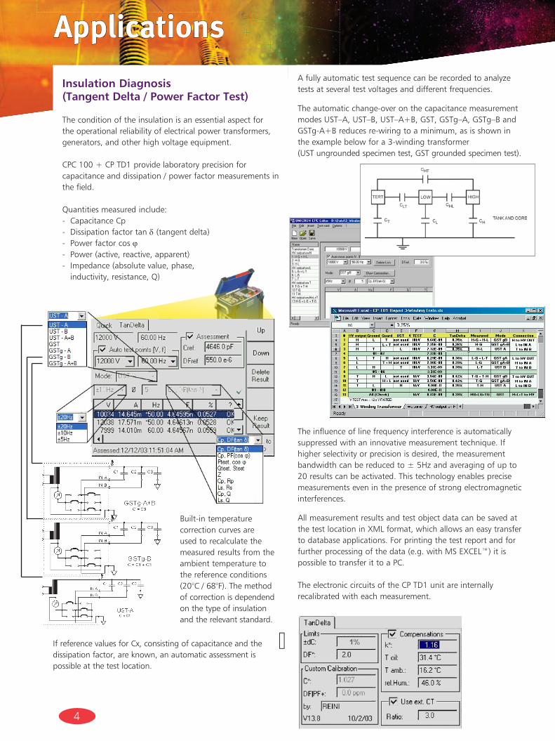
Afullyautomatictestsequencecanberecordedtoanalyzetests at several test voltages and different frequencies.
The automatic change-over on the capacitance measurement modesUST–A,UST–B,UST–A+B,GST,GSTg–A,GSTg–BandGSTg-A+Breducesre-wiringtoaminimum,asisshownintheexamplebelowfora3-windingtransformer (USTungroundedspecimentest,GSTgroundedspecimentest).
Applications
Built-in temperature correction curves are used to recalculate the measured results from the ambient temperature to the reference conditions (20°C/68°F).Themethodof correction is dependend on the type of insulation and the relevant standard.
The influence of line frequency interference is automatically suppressed with an innovative measurement technique. If higher selectivity or precision is desired, the measurement bandwidthcanbereducedto±5Hzandaveragingofupto20 results can be activated. This technology enables precise measurements even in the presence of strong electromagnetic interferences.
AllmeasurementresultsandtestobjectdatacanbesavedatthetestlocationinXMLformat,whichallowsaneasytransferto database applications. For printing the test report and for furtherprocessingofthedata(e.g.withMSEXCEL™)itispossible to transfer it to a PC.
The electronic circuits of the CP TD1 unit are internally recalibrated with each measurement.
insulation diagnosis (tangent delta / Power factor test)
The condition of the insulation is an essential aspect for the operational reliability of electrical power transformers, generators, and other high voltage equipment.
CPC100+CPTD1providelaboratoryprecisionforcapacitanceanddissipation/powerfactormeasurementsinthe field.
Quantities measured include:- Capacitance Cp- Dissipation factor tan δ(tangentdelta)- Power factor cos ϕ- Power(active,reactive,apparent)- Impedance(absolutevalue,phase,
inductivity, resistance, Q)
IfreferencevaluesforCx,consistingofcapacitanceandthedissipationfactor,areknown,anautomaticassessmentispossible at the test location.
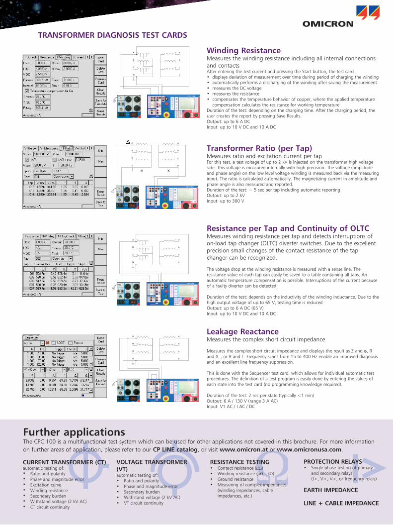
transformer ratio (per tap)MeasuresratioandexcitationcurrentpertapForthistest,atestvoltageofupto2kVisinjectedonthetransformerhighvoltageside.Thisvoltageismeasuredinternallywithhighprecision.Thevoltage(amplitudeandphaseangle)onthelowlevelvoltagewindingismeasuredbackviathemeasuringinput.Theratioiscalculatedautomatically.Themagnetizingcurrentinamplitudeandphase angle is also measured and reported.Duration of the test: ~ 5 sec per tap including automatic reportingOutput:upto2kVInput:upto300V
resistance per tap and continuity of oltc Measures winding resistance per tap and detects interruptions of on-loadtapchanger(OLTC)diverterswitches.Duetotheexcellentprecision small changes of the contact resistance of the tap changercanberecognized.
The voltage drop at the winding resistance is measured with a sense line. The resistancevalueofeachtapcaneasilybesavedtoatablecontainingalltaps.Anautomatic temperature compensation is possible. Interruptions of the current because of a faulty diverter can be detected.
Duration of the test: depends on the inductivity of the winding inductance. Due to the highoutputvoltageofupto65V,testingtimeisreducedOutput:upto6ADC(65V)Input:upto10VDCand10ADC
A a
B b
C c
N n
H X
A
B
C
N
a
b
c
n
leakage reactanceMeasuresthecomplexshortcircuitimpedance
MeasuresthecomplexshortcircuitimpedanceanddisplaystheresultasZandϕ, R and XL,orRandL.Frequencyscansfrom15to400Hzenableanimproveddiagnosisandanexcellentlinefrequencysuppression.
This is done with the Sequencer test card, which allows for individual automatic test procedures. The definition of a test program is easily done by entering the values of eachstateintothetestcard(noprogrammingknowledgerequired).
Durationofthetest:2secperstate(typically<1min)Output:6A/130V(range3AAC)Input:V1AC/IAC/DC
A
B
C
N
a
b
c
n
ProtectioN relays• Singlephasetestingofprimary
and secondary relays (I>,V>,V<,orfrequencyrelais)
earth imPedaNce
liNe + cable imPedaNce
resistaNce testiNg • Contactresistance(µW)• Windingresistance(µW-kW)• Groundresistance• Measuringofcompleximpedances(windingimpedances,cableimpedances, etc.)
Voltage traNsformer (Vt)automatic testing of:• Ratioandpolarity• Phaseandmagnitudeerror• Secondaryburden• Withstandvoltage(2kVAC)• VTcircuitcontinuity
curreNt traNsformer (ct)automatic testing of:• Ratio and polarity• Phase and magnitude error• Excitationcurve• Windingresistance• Secondary burden• Withstandvoltage(2kVAC)• CT circuit continuity
further applicationsThe CPC 100 is a multifunctional test system which can be used for other applications not covered in this brochure. For more information on further areas of application, please refer to our cP liNe catalog, or visit www.omicron.at or www.omicronusa.com.
winding resistanceMeasures the winding resistance including all internal connections and contactsAfterenteringthetestcurrentandpressingtheStartbutton,thetestcard• displaysdeviationofmeasurementovertimeduringperiodofchargingthewinding• automaticallyperformsadischargingofthewindingaftersavingthemeasurement• measurestheDCvoltage• measurestheresistance• compensatesthetemperaturebehaviorofcopper,wheretheappliedtemperaturecompensationcalculatestheresistanceforworkingtemperature
Durationofthetest:dependingonthechargingtime.Afterthechargingperiod,theuser creates the report by pressing Save Results.Output:upto6ADCInput:upto10VDCand10ADC
A
B
C
N
a
b
c
n
traNsformer diagNosis test cards
6
Technical Data
Guaranteedvaluesvalidoveroneyearwithin23°C±5°C(73°F±10°F),inthefrequency rangeof45...65HzorDC.Accuracyvaluesindicatethattheerrorissmallerthan+/-(Valueread*Readingerror+FullScaleoftherange*FullScaleError).1 Withmainsvoltage230Vwith2x6mhighcurrentcableat23°C±5°C(73°F±10°F) ambient
temperature.2 Signalsbelow50Hzorabove60Hzwithreducedvaluespossible.3 Outputcanbesynchronizedwithmains.4 Theinput/outputisprotectedwithlightningarrestorsbetweenthepinsandagainstprotective
earth. In case of energies above a few hundred Joule the lightning arrestors apply a permanent shortcircuittotheinput/output.
5 Signalsbelow50Hzorabove200Hzwithreducedvaluespossible.6 98%ofallunitshaveanaccuracybetterthanspecifiedasTypical.7 Input is galvanically separated from all other inputs.8 V1andV2aregalvanicallycoupledbutseparatedfromallotherinputs.9 Therearepowerrestrictionsformainsvoltagesbelow190VAC.10 Fuse protected.11 Error of reading < than ± value.
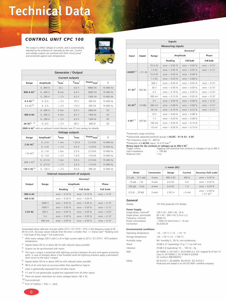
The output is either voltage or current, and is automatically selected by the software or manually by the user. Current and voltage outputs are overload and short circuit proof and protected against over temperature.
generalDisplay 1/4VGAgreyscaleLCDdisplay
Power supplySingle-phase, nominal9 100VAC...240VAC,16ASingle-phase,permissible 85VAC...264VAC(L-NorL-L)Frequency,nominal 50/60HzPowerconsumption <7000VAshorttime(<10sec)Connection IEC320/C20
environmental conditions
Operatingtemperature -10...+55°C(+14...+131°F)
Storagetemperature -20...+70°C(-4...+158°F)
Humidityrange Rel.humidity5...95%,non-condensing
Shock IEC68-2-27(operating)15g/11mshalfsine
Vibration IEC68-2-6(operating)10...150Hz:2g
EMC EN50081-2,EN55011,EN61000-3-2,FCCSubpartBofPart15ClassA,EN50082-2,IEC61000-4-2/3/4/8 CEconform(89/336/EEC)
Safety EN61010-1,EN60950,EN50191,IEC61010-1 Produced and tested in an EN ISO 9001 certified company
•Automaticrangeswitching•Galvanically separated potential groups: i ac/dc ; V1 & V2 ; V dc•ACfrequencyrange15-400Hz•Protection of i ac/dcinput:10AFFfuse4
binary input for dry contacts or voltages up to 300 V dc7
Triggercriteria Togglingwithpotentialfreecontactsorvoltagesofupto300V.Inputimpedance >100kWResponse time 1 ms
Control unit CPC 100
Voltage outputs
range amplitude5 tmax imax Powermax5
f
2 kV ac30...2kV 1 min 1.25A 2.5kVA 15-400Hz
0...2kV > 2 h 0.5A 1.0kVA 15-400Hz
1kVAC30...1kV 1 min 2.5A 2.5kVA 15-400Hz
0...1kV > 2 h 1.0A 1.0kVA 15-400Hz
500VAC30...0.5kV 1 min 5.0A 2.5kVA 15-400Hz
0...0.5kV > 2 h 2.0A 1.0kVA 15-400Hz
130 V ac10 0...130V > 2 h 3.0A 390VA 15-400Hz
generator / output
current outputs
range amplitude tmax1 Vmax
2 Powermax2
f
800 a ac3
0...800A 25 s 6.0V 4800VA 15-400Hz
0...400A 8min 6.4V 2560VA 15-400Hz
0...200A > 2 h 6.5V 1300VA 15-400Hz
6 a ac10 0...6A > 2 h 55V 330VA 15-400Hz
3AAC10 0...3A > 2 h 110V 330VA 15-400Hz
400 a dc
0...400A 2 min 6.5V 2600W DC
0...300A 3 min 6.5V 1950W DC
0...200A > 2 h 6.5V 1300W DC
6a dc4, 10 0...6A > 2 h 60V 360W DC
2000 a ac3withanoptionalCurrentBooster(seeCPLinecatalogfordetails).
W meter (dc)
mode connection range current accuracy (full scale)
0.5µW .. 12.5 mW 4-wire 400ADC 400A error<0.45%
10µW ... 1 W 4-wire 6ADC 6A error<0.35%
100µW ... 10 W 4-wire 6ADC 1A error<0.25%
0.2 W...20kW 2-wire VDCin <5mAerror<0.50% +0.1W11
inputs
measuring inputs
input imped. range
accuracy6
amplitude Phase
reading full scale full scale
i ac/dc4,7 < 0.1 W
10AAC error<0.05% error<0.05% error<0.10°
1AAC error<0.05% error<0.05% error<0.15°
10ADC error<0.03% error<0.08% -
1ADC error<0.03% error<0.08% -
V1 ac8 500kW
300V error<0.05% error<0.05% error<0.10°
30V error<0.05% error<0.05% error<0.10°
3V error<0.10% error<0.05% error<0.10°
300mV error<0.15% error<0.05% error<0.10°
V2 ac8 10 MW
3V error<0.03% error<0.08% error<0.10°
300mV error<0.08% error<0.08% error<0.10°
30mV error<0.10% error<0.25% error<0.15°
V dc4, 7 500kW
10V error<0.03% error<0.08% -
1V error<0.03% error<0.08% -
100mV error<0.05% error<0.10% -
10mV error<0.05% error<0.15% -
internal measurement of outputs
output range
accuracy6
amplitude Phase
reading full scale full scale
800 a ac - error<0.10% error<0.10% error<0.10°
400 a dc - error<0.20% error<0.05% -
2 kV ac
2000V error<0.05% error<0.05% error<0.10°
1000V error<0.05% error<0.05% error<0.15°
500V error<0.05% error<0.05% error<0.20°
5A error<0.20% error<0.05% error<0.10°
500mA error<0.05% error<0.05% error<0.10°
7
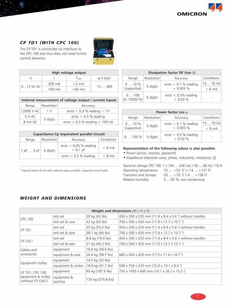
CP tD1 (with CPC 100)
1 Signalsbelow45Hzwithreducedvaluespossible.Capacitivelinearloads.
The CP TD1 is connected via interfaces to the CPC 100 and thus does not need further control elements.
representation of the following values is also possible:• Power(active,reactive,apparent)• Impedance(absolutevalue,phase,inductivity,resistance,Q)
NominalvoltageCPC100 1x100...240Vac/50...60Hz/16AOperatingtemperature -10…+55°C(+14...+131F)Transportandstorage -20…+70°C(-4...+158F)Relativehumidity 5...95%,noncondensing
weight anD Dimensions
high voltage output
V I tmax atf(Hz)1
0…12kVAC300mA >2 min
15…400100mA >60min
dissipation factor df (tan δ)
Range Resolution Accuracy Conditions
0…10% (capacitive)
5 digitserror<0.1%reading
+0.005%15...70Hz
<8mA
0 … 100 (0..10000%)
5 digitserror<0.5%reading
+0.02%-
internal measurement of voltage output / current inputs
Range Resolution Accuracy
12000VAC 1V error<0.3%reading+1V
5AAC5 digits
error<0.5%reading
8mAAC error<0.3%reading+100nA
capacitance cp (equivalent parallel circuit)
Range Resolution Accuracy Conditions
1pF…3µF 6digitserror<0.05%reading
+0.1pF<8mA
error<0.2%reading >8mA
Power factor cos ϕ
Range Resolution Accuracy Conditions
0…10% (capacitive)
5 digitserror<0.1%reading
+0.005%15...70Hz
<8mA
0…100% 5 digitserror<0.5%reading
+0.02%-
weight and dimensions (WxHxD)
CPC 100test set 29kg(63lbs) 450x330x220mm(11.4x8.4x5.6")withouthandles
test set & case 42kg(92lbs) 700x500x420mm(17.8x12.7x10.7")
CP TD1test set 25kg(55.2lbs) 450x330x220mm(11.4x8.4x5.6")withouthandles
test set & case 38.1kg(84lbs) 700x500x420mm(17.8x12.7x10.7")
CPCAL1test set 8.8kg(19.4lbs) 450x330x220mm(11.4x8.4x5.6")withouthandles
test set & case 21kg(46.3lbs) 700x500x420mm(17.8x12.7x10.7")
Cables and accessories
equipment 16.6kg(36.6lbs) -
equipment & case 26.6kg(58.7lbs) 680x450x420mm(17.3x11.4x10.7")
Equipment trolleyequipment 14.5kg(32lbs) -
equipment & carton 18.9kg(41.7lbs) 590x750x370mm(15.0x19.1x9.4")
CP TD1, CPC 100, equipment & trolley (withoutCPCAL1)
equipment 85kg(187.5lbs) 750x1050x600mm(19.1x26.7x15.2")
equipment & packing
125kg(275.8lbs) -
coNtact:
euroPe, africa, middle east OMICRONelectronicsGmbH,AustriaPhone:+435523507-0Fax:[email protected]
asia, PacificOMICRONelectronicsAsiaLimited,HongKongPhone:+85226340377Fax:[email protected]
North aNd south america OMICRONelectronicsCorp.USAPhone:+17138304660or1-800-OMICRONFax:[email protected]
www.omicron.at or www.omicronusa.com
©OMICRONL013 Subject to change without notice
Lastupdate:November2010
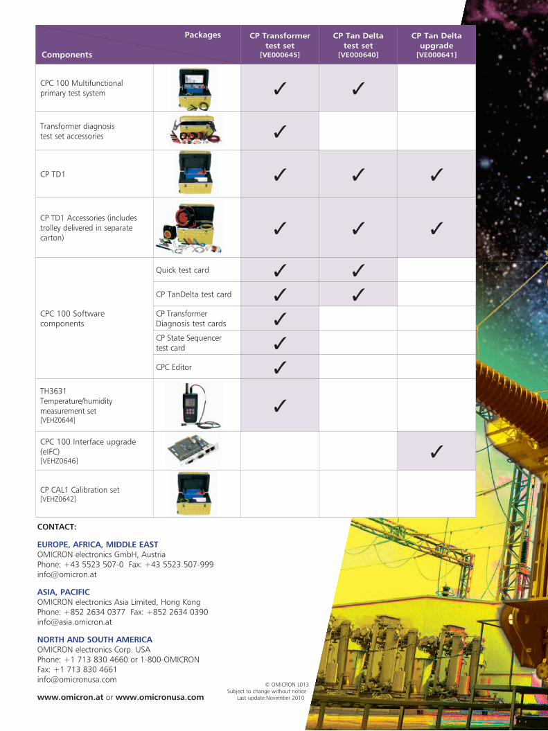
cP transformer test set
[Ve000645]
cP tan delta test set
[Ve000640]
cP tan delta upgrade
[Ve000641]
CPC 100 Multifunctional primary test system 3 3
Transformer diagnosis test set accessories 3
CP TD1 3 3 3
CPTD1Accessories(includestrolley delivered in separate carton)
3 3 3
CPC 100 Software components
Quicktestcard 3 3
CP TanDelta test card 3 3CP Transformer Diagnosis test cards 3CP State Sequencer test card 3
CPC Editor 3TH3631 Temperature/humiditymeasurement set [VEHZ0644]
3
CPC 100 Interface upgrade (eIFC)[VEHZ0646]
3
CPCAL1Calibrationset[VEHZ0642]
Packages
components