


γλώσσες
Σελίδες
Νομικός


RSC Advances
PAPER
Ope
n A
cces
s A
rtic
le. P
ublis
hed
on 0
8 D
ecem
ber
2017
. Dow
nloa
ded
on 3
/15/
2022
8:1
3:45
AM
. T
his
artic
le is
lice
nsed
und
er a
Cre
ativ
e C
omm
ons
Attr
ibut
ion
3.0
Unp
orte
d L
icen
ce.
View Article OnlineView Journal | View Issue
Shaping of porou
aResearch Group for Nanocatalysts, Korea R
Daejeon 305-600, Korea. E-mail: jschang@kbDepartment of Green Chemistry, Universit
Gajeong-Ro, Yuseong, Daejeon 305-350, KorcDepartment of Chemical Engineering, Chon
757, Korea. E-mail: [email protected] of Chemistry, Sungkyunkwan
† Electronic supplementary informa10.1039/c7ra11764g
Cite this: RSC Adv., 2017, 7, 55767
Received 25th October 2017Accepted 30th November 2017
DOI: 10.1039/c7ra11764g
rsc.li/rsc-advances
This journal is © The Royal Society of C
s metal–organic frameworkgranules using mesoporous r-alumina as a binder†
Anil H. Valekar,ab Kyung-Ho Cho,a U-Hwang Lee, *ab Ji Sun Lee,a Ji Woong Yoon,a
Young Kyu Hwang, ab Seung Gwan Lee,c Sung June Cho *c
and Jong-San Chang*ad
The shaping of metal–organic frameworks (MOFs) on a macroscopic level is a vibrant area in MOF research.
For practical application of MOFs, the fine microcrystalline powder should be converted into a shaped body
while preserving the powder's intrinsic properties. In this study, we prepared millimetre-scale spheres of
MIL-100(Fe), MIL-101(Cr), UiO-66(Zr), and UiO-66(Zr)_NH2 using the wet granulation method. The use
of mesoporous r-alumina (MRA) as a binder resulted in well-shaped MOF bodies which retained their
intrinsic properties after shaping. Furthermore, the performance of the MOF spheres was compared to
that of compressed pellets in terms of NH3 adsorption using a breakthrough test, and CO2 and N2
adsorption performance was compared using adsorption isotherms at 298 K between the powder and
spheres of MOFs for future industrial applications.
1. Introduction
Metal–organic frameworks (MOFs) are a class of promisingporous crystalline materials for potential application in gasstorage and separation, chemical sensing, heterogeneouscatalysis, etc.1–5 They have unique structural and texture char-acteristics like large surface areas, tunable pore-size distribu-tions, and coordinatively unsaturatedmetal sites (CUSs).6–8 Overthe past decade, many researchers and companies haveattempted to nd a commercial use for these appealing porousmaterials.9–12 However, there are several problems that need tobe addressed in order to successfully use MOFs for industrialand chemical engineering applications. The fundamental issuewith commercial applications is the highly pulverulent propertyof MOFs. One of the major strategies to overcome this problemhas been to produce macroscopic MOF bodies using variousshaping processes.
Shaped MOF bodies have been produced in the form ofpellets, tablets, monoliths, granules, and spheres using typicalshaping techniques like pressing, extrusion, granulation, andspray drying.13–17 In general, the shaped body of a porousmaterial provides improved handling, improved bulk density,
esearch Institute of Chemical Technology,
rict.re.kr; [email protected]
y of Science and Technology (UST), 217
ea
nam National University, Gwangju 500-
University, Suwon 440-476, Korea
tion (ESI) available. See DOI:
hemistry 2017
and reduced pressure drop for uid ow in packed bed systems.However, the chemical and mechanical sensitivities of MOFs tobinders, pressure-shaping process, etc. limit our ability to formthem into shaped bodies without losing their novel proper-ties.18,19 Therefore, to understand the pivotal importance of theshaping of MOFs, the prime objective of the current investiga-tion was to develop a facile shaping method using a versatilebinder suitable for use with variousMOFs while preserving theirspecic properties.
Recently, new strategies have been reported for fabricatingmacroscopic MOFs on a millimeter scale. Blom et al. preparedagglomerated spheres of CPO-27(Ni) using hydrocolloids andgelling agents as natural polymer binders by the “moleculargastronomy”method.20CPO-27(Ni) powder was formed into nicelyshaped spheres 2.5–3.5 mm in size and containing more than84 wt% of MOFs with minor loss in their weight-specic surfacearea (WSSA); the resulting spheres showed good mechanicalstrength. In another example, large-scale continuous neat melt-phase synthesis of ZiF-8 under solvent-free or low-solvent condi-tions was successfully demonstrated by James et al.21 Thisenhanced extrusion technique provided shaped bodies with highspace-time yields (STY) of up to 144 � 103 kg m�3. In the past,several research groups including ours reported the preparation ofwell-shaped MOFs using polymer, graphite and silica sol bindersfor a wide range of applications.16,22–28 However, the thermalstability of the shaped MOF bodies decreased owing to the lowdegradation temperature of the polymer binder. MOFs have alsobeen shaped by deposition onto range of metal surfaces, also withfollow-up the addition/coating of binders.29–32
Although most studies have focused on the shapingmethods, processes, or application of shaped MOFs, very few
RSC Adv., 2017, 7, 55767–55777 | 55767
RSC Advances Paper
Ope
n A
cces
s A
rtic
le. P
ublis
hed
on 0
8 D
ecem
ber
2017
. Dow
nloa
ded
on 3
/15/
2022
8:1
3:45
AM
. T
his
artic
le is
lice
nsed
und
er a
Cre
ativ
e C
omm
ons
Attr
ibut
ion
3.0
Unp
orte
d L
icen
ce.
View Article Online
studies have investigated the effect of the shaping process onthe intrinsic chemical properties of MOFs.33,34 Here, we presenta simple but effective granulation process to fabricate macro-scopic MOF bodies using amorphous-phase mesoporous r-alumina (MRA) as a binder. MRA can be used as hydratable andbondable alumina in the presence of a small amount ofa hydrophilic polar dispersionmedium like water or alcohol.35,36
The corresponding properties can be potential use for bindingMOF particles during the shaping process under ambientcondition. Indeed MRA requires no additional additives whereall the shaping process can be completed through wet granu-lation and subsequent drying in ambient air or elevatedtemperature. In this study, we prepared millimeter-scalespheres of MIL-100(Fe), MIL-101(Cr), UiO-66(Zr), and UiO-66(Zr)_NH2 using the wet granulation method. MRA bondedwith the MOFs without the substantial loss of the fundamentalproperties for example initial sorption capacity of the crystals.Thus, the formation of well-shaped bodies which can be easy-tohandle and also is scalable in large amount shown in thepresent work can be considered as a signicant step toward theindustrial-scale application and commercial application ofMOFs.
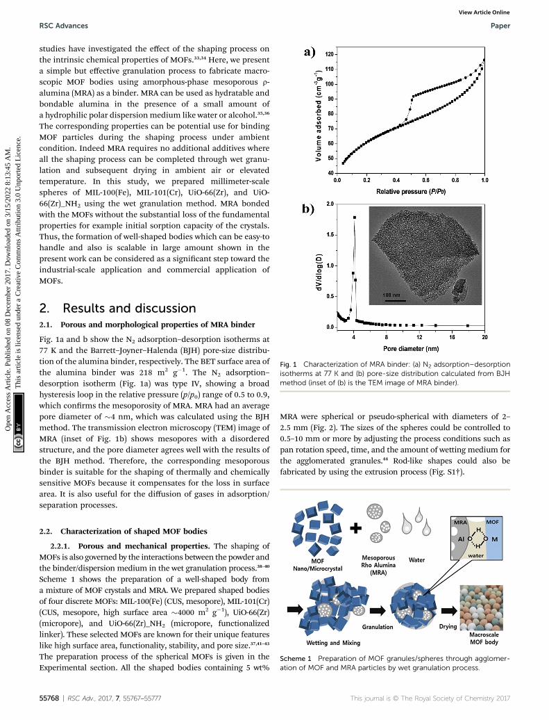
Fig. 1 Characterization of MRA binder: (a) N2 adsorption–desorptionisotherms at 77 K and (b) pore-size distribution calculated from BJHmethod (inset of (b) is the TEM image of MRA binder).
2. Results and discussion2.1. Porous and morphological properties of MRA binder
Fig. 1a and b show the N2 adsorption–desorption isotherms at77 K and the Barrett–Joyner–Halenda (BJH) pore-size distribu-tion of the alumina binder, respectively. The BET surface area ofthe alumina binder was 218 m2 g�1. The N2 adsorption–desorption isotherm (Fig. 1a) was type IV, showing a broadhysteresis loop in the relative pressure (p/p0) range of 0.5 to 0.9,which conrms the mesoporosity of MRA. MRA had an averagepore diameter of �4 nm, which was calculated using the BJHmethod. The transmission electron microscopy (TEM) image ofMRA (inset of Fig. 1b) shows mesopores with a disorderedstructure, and the pore diameter agrees well with the results ofthe BJH method. Therefore, the corresponding mesoporousbinder is suitable for the shaping of thermally and chemicallysensitive MOFs because it compensates for the loss in surfacearea. It is also useful for the diffusion of gases in adsorption/separation processes.
Scheme 1 Preparation of MOF granules/spheres through agglomer-ation of MOF and MRA particles by wet granulation process.
2.2. Characterization of shaped MOF bodies
2.2.1. Porous and mechanical properties. The shaping ofMOFs is also governed by the interactions between the powder andthe binder/dispersion medium in the wet granulation process.38–40
Scheme 1 shows the preparation of a well-shaped body froma mixture of MOF crystals and MRA. We prepared shaped bodiesof four discrete MOFs: MIL-100(Fe) (CUS, mesopore), MIL-101(Cr)(CUS, mesopore, high surface area �4000 m2 g�1), UiO-66(Zr)(micropore), and UiO-66(Zr)_NH2 (micropore, functionalizedlinker). These selected MOFs are known for their unique featureslike high surface area, functionality, stability, and pore size.37,41–43
The preparation process of the spherical MOFs is given in theExperimental section. All the shaped bodies containing 5 wt%
55768 | RSC Adv., 2017, 7, 55767–55777
MRA were spherical or pseudo-spherical with diameters of 2–2.5 mm (Fig. 2). The sizes of the spheres could be controlled to0.5–10 mm or more by adjusting the process conditions such aspan rotation speed, time, and the amount of wetting medium forthe agglomerated granules.44 Rod-like shapes could also befabricated by using the extrusion process (Fig. S1†).
This journal is © The Royal Society of Chemistry 2017
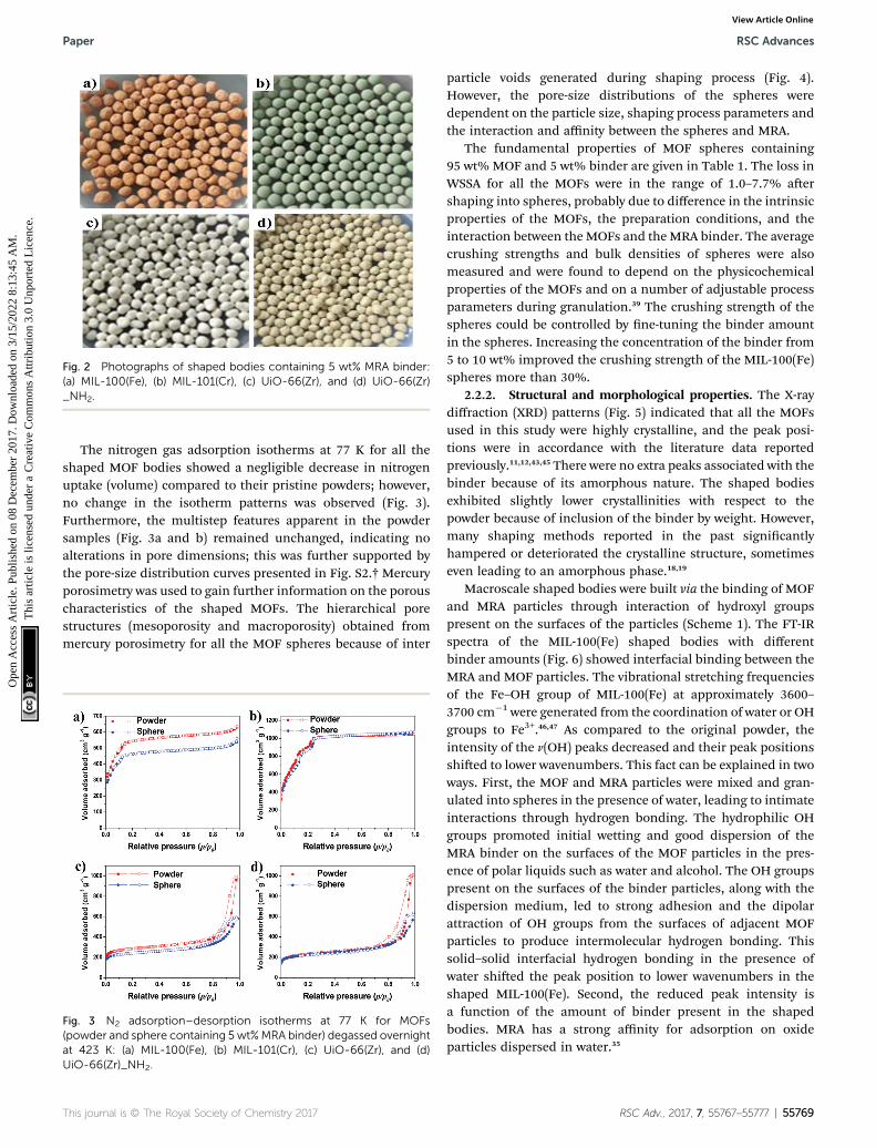
Fig. 2 Photographs of shaped bodies containing 5 wt% MRA binder:(a) MIL-100(Fe), (b) MIL-101(Cr), (c) UiO-66(Zr), and (d) UiO-66(Zr)_NH2.
Paper RSC Advances
Ope
n A
cces
s A
rtic
le. P
ublis
hed
on 0
8 D
ecem
ber
2017
. Dow
nloa
ded
on 3
/15/
2022
8:1
3:45
AM
. T
his
artic
le is
lice
nsed
und
er a
Cre
ativ
e C
omm
ons
Attr
ibut
ion
3.0
Unp
orte
d L
icen
ce.
View Article Online
The nitrogen gas adsorption isotherms at 77 K for all theshaped MOF bodies showed a negligible decrease in nitrogenuptake (volume) compared to their pristine powders; however,no change in the isotherm patterns was observed (Fig. 3).Furthermore, the multistep features apparent in the powdersamples (Fig. 3a and b) remained unchanged, indicating noalterations in pore dimensions; this was further supported bythe pore-size distribution curves presented in Fig. S2.† Mercuryporosimetry was used to gain further information on the porouscharacteristics of the shaped MOFs. The hierarchical porestructures (mesoporosity and macroporosity) obtained frommercury porosimetry for all the MOF spheres because of inter
Fig. 3 N2 adsorption–desorption isotherms at 77 K for MOFs(powder and sphere containing 5 wt%MRA binder) degassed overnightat 423 K: (a) MIL-100(Fe), (b) MIL-101(Cr), (c) UiO-66(Zr), and (d)UiO-66(Zr)_NH2.
This journal is © The Royal Society of Chemistry 2017
particle voids generated during shaping process (Fig. 4).However, the pore-size distributions of the spheres weredependent on the particle size, shaping process parameters andthe interaction and affinity between the spheres and MRA.
The fundamental properties of MOF spheres containing95 wt% MOF and 5 wt% binder are given in Table 1. The loss inWSSA for all the MOFs were in the range of 1.0–7.7% aershaping into spheres, probably due to difference in the intrinsicproperties of the MOFs, the preparation conditions, and theinteraction between the MOFs and theMRA binder. The averagecrushing strengths and bulk densities of spheres were alsomeasured and were found to depend on the physicochemicalproperties of the MOFs and on a number of adjustable processparameters during granulation.39 The crushing strength of thespheres could be controlled by ne-tuning the binder amountin the spheres. Increasing the concentration of the binder from5 to 10 wt% improved the crushing strength of the MIL-100(Fe)spheres more than 30%.
2.2.2. Structural and morphological properties. The X-raydiffraction (XRD) patterns (Fig. 5) indicated that all the MOFsused in this study were highly crystalline, and the peak posi-tions were in accordance with the literature data reportedpreviously.11,12,43,45 There were no extra peaks associated with thebinder because of its amorphous nature. The shaped bodiesexhibited slightly lower crystallinities with respect to thepowder because of inclusion of the binder by weight. However,many shaping methods reported in the past signicantlyhampered or deteriorated the crystalline structure, sometimeseven leading to an amorphous phase.18,19
Macroscale shaped bodies were built via the binding of MOFand MRA particles through interaction of hydroxyl groupspresent on the surfaces of the particles (Scheme 1). The FT-IRspectra of the MIL-100(Fe) shaped bodies with differentbinder amounts (Fig. 6) showed interfacial binding between theMRA and MOF particles. The vibrational stretching frequenciesof the Fe–OH group of MIL-100(Fe) at approximately 3600–3700 cm�1 were generated from the coordination of water or OHgroups to Fe3+.46,47 As compared to the original powder, theintensity of the n(OH) peaks decreased and their peak positionsshied to lower wavenumbers. This fact can be explained in twoways. First, the MOF and MRA particles were mixed and gran-ulated into spheres in the presence of water, leading to intimateinteractions through hydrogen bonding. The hydrophilic OHgroups promoted initial wetting and good dispersion of theMRA binder on the surfaces of the MOF particles in the pres-ence of polar liquids such as water and alcohol. The OH groupspresent on the surfaces of the binder particles, along with thedispersion medium, led to strong adhesion and the dipolarattraction of OH groups from the surfaces of adjacent MOFparticles to produce intermolecular hydrogen bonding. Thissolid–solid interfacial hydrogen bonding in the presence ofwater shied the peak position to lower wavenumbers in theshaped MIL-100(Fe). Second, the reduced peak intensity isa function of the amount of binder present in the shapedbodies. MRA has a strong affinity for adsorption on oxideparticles dispersed in water.35
RSC Adv., 2017, 7, 55767–55777 | 55769
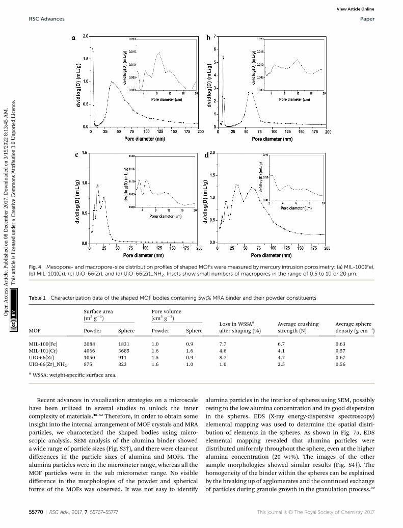
Fig. 4 Mesopore- and macropore-size distribution profiles of shaped MOFs were measured by mercury intrusion porosimetry: (a) MIL-100(Fe),(b) MIL-101(Cr), (c) UiO-66(Zr), and (d) UiO-66(Zr)_NH2. Insets show small numbers of macropores in the range of 0.5 to 10 or 20 mm.
Table 1 Characterization data of the shaped MOF bodies containing 5wt% MRA binder and their powder constituents
MOF
Surface area(m2 g�1)
Pore volume(cm3 g�1)
Loss in WSSAa
aer shaping (%)Average crushingstrength (N)
Average spheredensity (g cm�3)Powder Sphere Powder Sphere
MIL-100(Fe) 2088 1831 1.0 0.9 7.7 6.7 0.63MIL-101(Cr) 4066 3685 1.6 1.6 4.6 4.1 0.57UIO-66(Zr) 1050 911 1.5 0.9 8.7 4.7 0.67UIO-66(Zr)_NH2 875 823 1.6 1.0 1.0 2.5 0.56
a WSSA: weight-specic surface area.
RSC Advances Paper
Ope
n A
cces
s A
rtic
le. P
ublis
hed
on 0
8 D
ecem
ber
2017
. Dow
nloa
ded
on 3
/15/
2022
8:1
3:45
AM
. T
his
artic
le is
lice
nsed
und
er a
Cre
ativ
e C
omm
ons
Attr
ibut
ion
3.0
Unp
orte
d L
icen
ce.
View Article Online
Recent advances in visualization strategies on a microscalehave been utilized in several studies to unlock the innercomplexity of materials.48–52 Therefore, in order to obtain someinsight into the internal arrangement of MOF crystals and MRAparticles, we characterized the shaped bodies using micro-scopic analysis. SEM analysis of the alumina binder showeda wide range of particle sizes (Fig. S3†), and there were clear-cutdifferences in the particle sizes of alumina and MOFs. Thealumina particles were in the micrometer range, whereas all theMOF particles were in the sub micrometer range. No visibledifference in the morphologies of the powder and sphericalforms of the MOFs was observed. It was not easy to identify
55770 | RSC Adv., 2017, 7, 55767–55777
alumina particles in the interior of spheres using SEM, possiblyowing to the low alumina concentration and its good dispersionin the spheres. EDS (X-ray energy-dispersive spectroscopy)elemental mapping was used to determine the spatial distri-bution of elements in the spheres. As shown in Fig. 7a, EDSelemental mapping revealed that alumina particles weredistributed uniformly throughout the sphere, even at the higheralumina concentration (20 wt%). The images of the othersample morphologies showed similar results (Fig. S4†). Thehomogeneity of the binder within the spheres can be explainedby the breaking up of agglomerates and the continued exchangeof particles during granule growth in the granulation process.39
This journal is © The Royal Society of Chemistry 2017
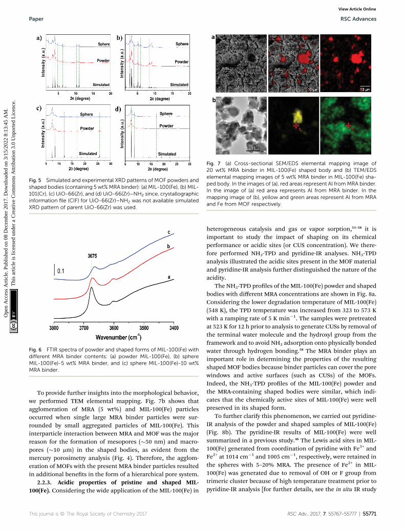
Fig. 5 Simulated and experimental XRD patterns of MOF powders andshaped bodies (containing 5 wt%MRA binder): (a) MIL-100(Fe), (b) MIL-101(Cr), (c) UiO-66(Zr), and (d) UiO-66(Zr)–NH2 since, crystallographicinformation file (CIF) for UiO-66(Zr)–NH2 was not available simulatedXRD pattern of parent UiO-66(Zr) was used.
Fig. 6 FTIR spectra of powder and shaped forms of MIL-100(Fe) withdifferent MRA binder contents: (a) powder MIL-100(Fe), (b) sphereMIL-100(Fe)-5 wt% MRA binder, and (c) sphere MIL-100(Fe)-10 wt%MRA binder.
Fig. 7 (a) Cross-sectional SEM/EDS elemental mapping image of20 wt% MRA binder in MIL-100(Fe) shaped body and (b) TEM/EDSelemental mapping images of 5 wt% MRA binder in MIL-100(Fe) sha-ped body. In the images of (a), red areas represent Al fromMRA binder.In the image of (a) red area represents Al from MRA binder. In themapping image of (b), yellow and green areas represent Al from MRAand Fe from MOF respectively.
Paper RSC Advances
Ope
n A
cces
s A
rtic
le. P
ublis
hed
on 0
8 D
ecem
ber
2017
. Dow
nloa
ded
on 3
/15/
2022
8:1
3:45
AM
. T
his
artic
le is
lice
nsed
und
er a
Cre
ativ
e C
omm
ons
Attr
ibut
ion
3.0
Unp
orte
d L
icen
ce.
View Article Online
To provide further insights into the morphological behavior,we performed TEM elemental mapping. Fig. 7b shows thatagglomeration of MRA (5 wt%) and MIL-100(Fe) particlesoccurred when single large MRA binder particles were sur-rounded by small aggregated particles of MIL-100(Fe). Thisinterparticle interaction between MRA and MOF was the majorreason for the formation of mesopores (�50 nm) and macro-pores (�10 mm) in the shaped bodies, as evident from themercury porosimetry analysis (Fig. 4). Therefore, the agglom-eration of MOFs with the present MRA binder particles resultedin additional benets in the form of a hierarchical pore system.
2.2.3. Acidic properties of pristine and shaped MIL-100(Fe). Considering the wide application of the MIL-100(Fe) in
This journal is © The Royal Society of Chemistry 2017
heterogeneous catalysis and gas or vapor sorption,53–58 it isimportant to study the impact of shaping on its chemicalperformance or acidic sites (or CUS concentration). We there-fore performed NH3-TPD and pyridine-IR analyses. NH3-TPDanalysis illustrated the acidic sites present in the MOF materialand pyridine-IR analysis further distinguished the nature of theacidity.
The NH3-TPD proles of the MIL-100(Fe) powder and shapedbodies with different MRA concentrations are shown in Fig. 8a.Considering the lower degradation temperature of MIL-100(Fe)(548 K), the TPD temperature was increased from 323 to 573 Kwith a ramping rate of 5 K min�1. The samples were pretreatedat 523 K for 12 h prior to analysis to generate CUSs by removal ofthe terminal water molecule and the hydroxyl group from theframework and to avoid NH3 adsorption onto physically bondedwater through hydrogen bonding.58 The MRA binder plays animportant role in determining the properties of the resultingshaped MOF bodies because binder particles can cover the porewindows and active surfaces (such as CUSs) of the MOFs.Indeed, the NH3-TPD proles of the MIL-100(Fe) powder andthe MRA-containing shaped bodies were similar, which indi-cates that the chemically active sites of MIL-100(Fe) were wellpreserved in its shaped form.
To further clarify this phenomenon, we carried out pyridine-IR analysis of the powder and shaped samples of MIL-100(Fe)(Fig. 8b). The pyridine-IR results of MIL-100(Fe) were wellsummarized in a previous study.46 The Lewis acid sites in MIL-100(Fe) generated from coordination of pyridine with Fe3+ andFe2+ at 1014 cm�1 and 1005 cm�1, respectively, were retained inthe spheres with 5–20% MRA. The presence of Fe2+ in MIL-100(Fe) was generated due to removal of OH or F group fromtrimeric cluster because of high temperature treatment prior topyridine-IR analysis [for further details, see the in situ IR study
RSC Adv., 2017, 7, 55767–55777 | 55771

Fig. 8 (a) NH3-TPD profiles and (b) pyridine-IR spectra of MIL-100(Fe)powder and spheres with 5, 10, and 20 wt% MRA binder.
RSC Advances Paper
Ope
n A
cces
s A
rtic
le. P
ublis
hed
on 0
8 D
ecem
ber
2017
. Dow
nloa
ded
on 3
/15/
2022
8:1
3:45
AM
. T
his
artic
le is
lice
nsed
und
er a
Cre
ativ
e C
omm
ons
Attr
ibut
ion
3.0
Unp
orte
d L
icen
ce.
View Article Online
of MIL-100(Fe) in the ESI, Fig. S5†].46 No signicant variation inthe strength of the peaks was observed. The decrease in theacidity was proportional to the binder content, which can dilutethe acidity of MOFs. A similar dilution effect was observed for H-ZSM-5 zeolite by IR and TPD analyses aer being shaped intogranules using an attapulgite clay binder.59 The aforementionedresults conrmed that the CUSs of MIL-100(Fe) were unaffectedby the shaping process and the use of MRA binder.
Fig. 9 NH3 breakthrough test of shaped MIL-100(Fe) bodies (spheres)containing 5 wt% MRA binder and a pellet fabricated by using thepressing method with 3 wt% of graphite as the binder at 298 K.Amounts of NH3 calculated for sphere (4.4 mmol g�1) and pellet(3.6 mmol g�1) were normalized to the MIL-100(Fe) content present.
2.3. Ammonia adsorption on shaped bodies of MIL-100(Fe)
Recently, toxic gas adsorption, particularly that of ammonia,over porous solid materials has attracted the attention of manyresearchers.58,60–62 Considerable effort has been made to choosea potential material for the adsorption of ammonia gas. Ban-dosz et al. comprehensively studied MIL-100(Fe) and an MIL-100(Fe)-GO composite material for this purpose.58 ConsideringMIL-100(Fe) as a potential candidate for NH3 adsorption, itspractical implementation motivated us to perform NH3 break-through tests using shaped bodies of MIL-100(Fe). We alsoinvestigated how the binder and shaping method affect the NH3
adsorption performance of MIL-100(Fe). Generally, NH3, withits free lone pair of electrons, tends to bind with electron-decient species through a coordinative covalent bond. It iswell documented that several MOFs, including MIL-100(Fe),have Lewis acidity due to the presence of CUSs.8,63 Therefore,
55772 | RSC Adv., 2017, 7, 55767–55777
NH3 can easily form coordinate bonds with the CUSs of MIL-100(Fe).
The NH3 breakthrough results obtained for granulated andconventional pellets of MIL-100(Fe) are shown in Fig. 9. The testwas carried out at 298 K under dry conditions using samplesthat were pretreated at 423 K for 12 h prior to the breakthroughtest. The ammonia uptake capacity of MIL-100(Fe) spheres(4.4 mmol g�1) was higher than that of MIL-100(Fe) pellets(3.6 mmol g�1), which conrms that the pore structure andCUSs of MIL-100(Fe) spheres were not signicantly affected bythe shaping (granulation) process. The ammonia uptakecapacity of MIL-100(Fe) reported here is somewhat higher thanthat previously reported (4.3 mmol g�1).58 On the other hand,shaping MIL-100(Fe) by pressing affects the crystal structureand porosity (Fig. S6†), which subsequently lowers the adsorp-tion of ammonia as compared to the spheres prepared in thepresent work. We further checked the effect of pressure-dependent pelletization on the physicochemical properties ofMIL-101(Cr) in detail (Fig. S7†), and the obtained results were inline with the results obtained for MIL-100(Fe). Additionally, wehave summarized the other shaping strategies utilized previ-ously in the literature for shaping of MOFs and their effects onits porous properties [Table S1†].
2.4. CO2 adsorption on powder and shaped bodies of MIL-101(Cr), UiO-66(Zr) and UiO-66(Zr)_NH2
Metal�organic frameworks (MOFs) have been extensivelyinvestigated for the adsorption of CO2.64 In recent years,adsorption-based post combustion CO2 capture has alsoreceived great attention.65,66 The adsorbents for this processshould have high CO2 uptake at lower pressure (0.15 bar) underambient temperature such as 298 K, good CO2/N2 selectivity andexcellent water stability.64 MOFs have been demonstrated withgreat potential for this purpose.64 The MOFs reported herein
This journal is © The Royal Society of Chemistry 2017

Fig. 10 CO2 and N2 adsorption isotherms at 298 K for MOFs powder and sphere (containing 5 wt%MRA binder) degassed overnight at 150 �C: (a)UiO-66(Zr), (b) UiO-66(Zr)_NH2, and (c) MIL-101(Cr).
Paper RSC Advances
Ope
n A
cces
s A
rtic
le. P
ublis
hed
on 0
8 D
ecem
ber
2017
. Dow
nloa
ded
on 3
/15/
2022
8:1
3:45
AM
. T
his
artic
le is
lice
nsed
und
er a
Cre
ativ
e C
omm
ons
Attr
ibut
ion
3.0
Unp
orte
d L
icen
ce.
View Article Online
have excellent water stability which allowed us to evaluate theirperformance in CO2 and N2 capture at low pressure (up to 1 bar).
There isminor difference in CO2 adsorbed on the powder withrespect to the spheres of MOFs (Fig. 10). This difference inuptakes is in accordance with the difference in surface area ofpowder and sphere samples (Table 1). MIL-101(Cr) is a veryprominent example of MOFs that possess unsaturated metalsites.37,45 It can capture CO2 in its pores through physisorption aswell as through a Lewis acid�base interaction between thecoordinatively unsaturated Cr(III) sites, and O atoms in CO2
molecule.66 It exhibits high CO2 adsorption capacity at lowerpressure (25.9 cm3 g�1), which has not inuenced much aershaping into spears (24.5 cm3 g�1). At 0.15 bar pressure UiO-66(Zr)_NH2 adsorb higher CO2 (6.8 cm
3 g�1) compared to pristineUiO-66(Zr) (5.4 cm3 g�1). MOFs containing polar functionalgroups tend to have stronger interactions with CO2 leading tohigher adsorption volume.66–68 However, at higher pressure (1bar), physisorption occurs which leads to almost similar overallCO2 adsorption capacity for UiO-66(Zr)–NH2 and its pristine form(27.4 cm3 g�1). Nevertheless, CO2 adsorption capacity of UiO-66(Zr) and its NH2 functionalized analogs did not change muchaer shaping into spheres. N2 uptake of powder and spheres ofMOFs is almost same.Moreover, CO2/N2 sorption ratios at 1.0 barwere 12, 10.9 and 7 for shaped samples of UiO-66(Zr), UiO-66(Zr)–NH2 and MIL-101(Cr) respectively, which indicating high affinityfor CO2 over N2 in all MOF samples tested here. Further researchis in progress to evaluate the adsorption behavior of series ofgasses over various MRA shaped MOFs bodies. These results
This journal is © The Royal Society of Chemistry 2017
strongly imply that physical as well as chemical properties ofMOFs (surface area, functionality and CUSs) remain intact aershaping them into spheres using MRA binder.
3. Conclusions
We successfully fabricated shaped bodies of MIL-100(Fe), MIL-101(Cr), UiO-66(Zr), and UiO-66(Zr)_NH2 using MRA binder. TheMOFs were prepared to have a macroscopic structure on a milli-meter scale with small loss of WSSA and increased bulk density.Advanced visualization tools were utilized to unlock the innercomplexity of the shaped MOF bodies. It is of interest that theMOF shaped bodies retained their intrinsic properties aershaping, which was conrmed by gas adsorption, NH3-TPD, andpyridine-IR measurements. The possible adverse effect of thebinder on the chemical properties of the shaped MOFs wasstudied in detail in order to determine their potential for practicalapplications. Additionally, results of an NH3 breakthrough testusingMIL-100(Fe) spheres and CO2 adsorption usingMIL-101(Cr),UiO-66(Zr) and UiO-66(Zr)_NH2 spheres showed the potential ofour shaping method for use in practical applications for MOFs.
4. Experimental section4.1. MOF synthesis
4.1.1. Synthesis of MIL-100(Fe). MIL-100(Fe) was synthe-sized using the scaled-up method previously reported by ourresearch group.11 Briey, Fe(NO3)3$9H2O was completely
RSC Adv., 2017, 7, 55767–55777 | 55773
RSC Advances Paper
Ope
n A
cces
s A
rtic
le. P
ublis
hed
on 0
8 D
ecem
ber
2017
. Dow
nloa
ded
on 3
/15/
2022
8:1
3:45
AM
. T
his
artic
le is
lice
nsed
und
er a
Cre
ativ
e C
omm
ons
Attr
ibut
ion
3.0
Unp
orte
d L
icen
ce.
View Article Online
dissolved in water. Then, trimesic acid (BTC) was added to thesolution; the resultingmixture was stirred at room temperature for1 h. The nal composition was Fe(NO3)3$9H2O : 0.67BTC : xH2O(x ¼ 55–280). The reactant mixture was heated at 433 K for12 h using a Teon-lined pressure vessel. The synthesized sol-id was ltered and washed with deionized (DI) water.Further washing was carried out with DI water and ethanol at343 K for 3 h and puried with a 38 mM NH4F solution at 343 Kfor 3 h. The solid was nally dried overnight at less than 373 Kin air.
4.1.2. Synthesis of MIL-101(Cr). MIL-101(Cr) was synthe-sized according to a previous report.37 In brief, H2BDC(1 mmol), Cr(NO3)3$9H2O (1 mmol), hydrouoric acid(0.25 mmol), and H2O (265 mmol) were mixed in a Teon-linedhydrothermal reactor and heated at 493 K for 8 h. The obtainedgreen solid product was ltered and washed with DI water. Next,the solid was immersed in an ethanol/water mixture (95%ethanol and 5% water) and stirred at 343 K for 24 h. Furtherpurication of the solid was carried out by treating it witha 30 mM aqueous solution of NH4F at 343 K for 10 h. Finally, thesample was dried at 373 K for 12 h in a vacuum oven.
4.1.3. Synthesis of UiO-66(Zr). The scaled-up synthesis ofUiO-66(Zr) was carried out in a 5 L glass reactor (Reactor Master,Syrris, equipped with reux condenser and a Teon-linedmechanical stirrer) according to a previously reportedmethod.12 In short, 462 g (2.8 mol) of H2BDC (98%) was initiallydissolved in 2.5 L of dimethyl formamide (DMF, 2.36 kg,32.3 mol) at room temperature. Then, 896 g (2.8 mol) ofZrOCl2$8H2O (98%) and 465 mL of 37% HCl (548 g, 15 mol)were added to the mixture. The molar ratio of the nalZrOCl2$8H2O/H2BDC/DMF/HCl mixture was 1 : 1 : 11.6 : 5.4.The reaction mixture was vigorously stirred to obtain a homo-geneous gel. The mixture was then heated to 423 K at a rate of1 K min�1 and maintained at this temperature for 6 h in thereactor without stirring, leading to a crystalline UiO-66(Zr) solid.The resulting product (�510 g) was recovered from the slurry byltration, redispersed in 7 L of DMF at 333 K for 6 h understirring, and recovered by ltration. The same procedure wasrepeated twice, using methanol (MeOH) instead of DMF. Thesolid product was nally dried at 373 K overnight.
4.1.4. Synthesis of UiO-66(Zr)_NH2. UiO-66(Zr)_NH2 wassynthesized by the reux method. Initially, 250 mL of DMF waspoured into a 500 mL round-bottom ask. Next, ZrOCl2$8H2O(16.11 g, 0.05 mol), 2-amino-1,4-benzenedicarboxylic acid(9.06 g, 0.05 mol), and HCl (8.35 mL, 0.27 mol) were added tothe round-bottom ask containing DMF. The reaction solutionwas heated to 426 K and held at this temperature for 24 h. Aercooling to room temperature, the yellow precipitate was lteredoff and washed with DMF, followed byMeOH (twice) at 333 K for2 h to remove unreacted ligand moieties from the pores. Thepuried yellowish powder was then dried at 373 K in an oven for12 h.
4.2. Preparation of MRA binder
Al(OH)3 (7 mm, KC Chemical Corp.) was used as the startingmaterial to prepare mesoporous alumina by the ash pyrolysis
55774 | RSC Adv., 2017, 7, 55767–55777
method. The preparation method of the alumina binder wasreported by Cho and co-workers.35,36 Briey, Al(OH)3 was pyro-lyzed for a few seconds at 800–1000 K in order to obtain ash-calcined alumina. To achieve such a fast dehydration, Al(OH)3was dropped into a tubular furnace under vigorous vibrationthat had been preheated to the desired temperature. Thepowder was collected at the bottom of the furnace. The bulkdensity of the obtained powder was measured to ensure theash calcination upon dehydration and subsequently wassealed tightly in polypropylene bottle for further use during thehydration in tubular furnace, Al(OH)3 was converted into mes-oporous rehydratable alumina (MRA).
4.3. Preparation of spheres and pellets
Spheres of the various MOFs were prepared using the conven-tional granulation method. In brief, known amounts of MOFpowder (for e.g. 10–100 g), MRA binder (5–20 wt% for MOFpowder), and dispersion medium (water) were mixed usinga hand-made pan-type granulator. During the mixing process,the requisite amount of water was briey sprayed onto thesamples to achieve the desired particle growth. Granules witha wider size distribution were thus produced. Aer sieving, thegranules (2.0–2.5 mm) were rolled using a roller machine toenhance the spherical shape. The samples were then dried fromroom temperature to 383 K for 12 h in a vacuum oven to removethe water from the spheres.
Pellets were prepared by mixing a known amount of MOFpowder (50–100 mg) and 3 wt% graphite binder powder. Thispowder mixture then transferred into a multiple cylindrical dies(diameter 3 mm, length 10 mm) and the dies were closed usinga stainless steel dowels. The assembly was pressed in manualhydraulic press to 5000 psi (34 MPa) and held this pressure for1 min. The prepared pellets were 3.0 mm in diameter and4.0 mm in length.
4.4. Characterization
Powder X-ray diffraction patterns of all MOF powders and sha-ped bodies were obtained by a Rigaku diffractometer (D/MAXIIB, 2 kW) using Ni-ltered Cu Ka radiation (40 kV, 30 mA, l¼ 1.5406 A). The N2 adsorption isotherms were measured at 77K using a Micromeritics Tristar 3000 system. The samples weredehydrated under vacuum at 423 K for 12 h prior to analysis.The specic surface areas were evaluated using the Brunauer–Emmett–Teller (BET) method and the pore volume was deter-mined by the single-point method at p/p0 ¼ 0.99. The macro-scale pore-size distribution of the MOF spheres was measuredusing amercury porosimeter (Micromeritics, Autopore III 9420).The sphere densities were estimated from the mass and phys-ical dimensions of individual spheres. Ten well-shaped sphereswere selected to calculate the average sphere density. Thecrushing strengths of the spheres and pellets were measuredusing the strength meter described in our previous paper.22 Foreach sample, the average crushing strength of at least 10 indi-vidual spheres or pellets was considered. The internal crosssections of the spheres were examined to study the distributionof the binder particles, as well as their arrangements with MOF
This journal is © The Royal Society of Chemistry 2017
Paper RSC Advances
Ope
n A
cces
s A
rtic
le. P
ublis
hed
on 0
8 D
ecem
ber
2017
. Dow
nloa
ded
on 3
/15/
2022
8:1
3:45
AM
. T
his
artic
le is
lice
nsed
und
er a
Cre
ativ
e C
omm
ons
Attr
ibut
ion
3.0
Unp
orte
d L
icen
ce.
View Article Online
particles, using scanning electron microscopy (SEM) (TescanMira 3 LMU FEG with an accelerating voltage of 10 kV) and X-rayenergy-dispersive spectroscopy (EDS) (Bruker, Quantax 200equipped with a Si Dri Detector). Scanning transmissionelectron microscopy (STEM)-EDS measurements were taken ona FEI Tecnai G2 T20 S microscope with an accelerating voltageof 200 kV. The NH3 temperature-programmed desorption (TPD)proles of the binders, MOF powders, and spheres weremeasured on a Micromeritics AutoChem II 2920 V3.05 systemequipped with a thermal conductivity detector. Samples wereactivated at 523 K for 12 h in He ow prior to the adsorptionstep. Subsequently, the activated samples were exposed to NH3
at 373 K for 1 h at a ow rate of 50 mL min�1. Physicallyadsorbed NH3 was removed by purging with helium gas at thesame temperature for 1 h. TPD data was recorded from 313 to673 K at a heating rate of 5 K min�1. The Fourier-transforminfrared (FT-IR) spectra of adsorbed pyridine (Aldrich, 99.8%)were obtained at room temperature using a Nicolet FT-IRspectrometer (iS50). For this purpose, the MIL-100(Fe) powderwas pelletized to a wafer (10 mg cm�2) and evacuated for 2 h at423 K and 523 K under vacuum (�10�6 Torr), respectively. Aerthe adsorption of pyridine at room temperature, the adsorbedpyridine was evacuated for 30 min at 298–523 �C, respectively.For temperature-dependent FT-IR analyses, samples werepressed into self-supported wafers and the spectra were recor-ded at 323 K aer evacuation for 2 h under vacuum (�10�6 Torr)at the same temperature.
4.5. Ammonia breakthrough test
To perform the NH3 breakthrough test, �0.246 mL of 60–70-mesh-sieved samples was loaded into a 3.96 mm (i.d.) quartztube reactor. Before the breakthrough test, each sample wasactivated for 12 h at 423 K under 20 mL min�1 He ow. Theconcentration of the mixed ammonia/air balanced gas was1000 ppm and the total ow rate was 43.6 mL min�1. Thecontact time and linear velocity of the 1000 ppm NH3/airmixture gas penetrating the samples were 0.399 s and5.9 cm s�1, respectively. During the breakthrough test forammonia, the concentration of effluent gas was determinedusing a tunable diode-laser NH3 gas detector. The amount ofadsorbed NH3 was calculated by integrating the breakthroughcurve for the sample subtracted from the integration of thebreakthrough curve for the blank test.
4.6. CO2 adsorption
CO2 sorption isotherms of MOFs were measured up to 1 barusing a Micromeritics Tristar 3020 analyzer. Before themeasurements, the sample (�150 mg) was degassed underreduced pressure at 423 K for 12 h. The CO2 adsorption volumesfor MOFs at 298 K were then measured.
Conflicts of interest
There are no conicts to declare.
This journal is © The Royal Society of Chemistry 2017
Acknowledgements
This work was supported by the Center for Hybrid InterfaceMaterials (HIM) for the Global Frontier R&D Program(2013M3A6B1073298), funded by the Ministry of Science, ICT &Future Planning (MSIP), and the R&D Convergence Program(CRC 14-1-KRICT) of National Research Council of Science &Technology (NST) of the Republic of Korea.
References
1 J. A. Mason, M. Veenstra and J. R. Long, Chem. Sci., 2014, 5,32–51.
2 J. R. Li, R. J. Kuppler and H. C. Zhou, Chem. Soc. Rev., 2009,38, 1477–1504.
3 L. E. Kreno, K. Leong, O. K. Farha, M. Allendorf, R. P. VanDuyne and J. T. Hupp, Chem. Rev., 2012, 112, 1105–1125.
4 J. Liu, L. Chen, H. Cui, J. Zhang, L. Zhang and C. Y. Su, Chem.Soc. Rev., 2014, 43, 6011–6061.
5 A. H. Valekar, K.-H. Cho, S. K. Chitale, D.-Y. Hong, G.-Y. Cha,U.-H. Lee, D. W. Hwang, C. Serre, J.-S. Chang andY. K. Hwang, Green Chem., 2016, 18, 4542–4552.
6 G. Ferey, Chem. Soc. Rev., 2008, 37, 191–214.7 M. Eddaoudi, J. Kim, N. Rosi, D. Vodak, J. Wachter,M. O'Keeffe and O. M. Yaghi, Science, 2002, 295, 469–472.
8 D. Y. Hong, Y. K. Hwang, C. Serre, G. Ferey and J. S. Chang,Adv. Funct. Mater., 2009, 19, 1537–1552.
9 A. U. Czaja, N. Trukhan and U. Muller, Chem. Soc. Rev., 2009,38, 1284–1293.
10 N. Stock and S. Biswas, Chem. Rev., 2012, 112, 933–969.11 Y. K. Seo, J. W. Yoon, J. S. Lee, U. H. Lee, Y. K. Hwang,
C. H. Jun, P. Horcajada, C. Serre and J. S. Chang,Microporous Mesoporous Mater., 2012, 157, 137–145.
12 F. Ragon, P. Horcajada, H. Chevreau, Y. K. Hwang, U. H. Lee,S. R. Miller, T. Devic, J. S. Chang and C. Serre, Inorg. Chem.,2014, 53, 2491–2500.
13 R. Zacharia, D. Cossement, L. La and R. Chahine, J. Mater.Chem., 2010, 20, 2145–2151.
14 A. M. Ribeiro, M. C. Campo, G. Narin, J. C. Santos,A. Ferreira, J. S. Chang, Y. K. Hwang, Y. K. Seo, U. H. Lee,J. M. Loureiro and A. E. Rodrigues, Sep. Purif. Technol.,2013, 110, 101–111.
15 A. F. P. Ferreira, J. C. Santos, M. G. Plaza, N. Lamia,J. M. Loureiro and A. E. Rodrigues, Chem. Eng. J., 2011,167, 1–12.
16 M. G. Plaza, A. M. Ribeiro, A. Ferreira, J. C. Santos, U. H. Lee,J. S. Chang, J. M. Loureiro and A. E. Rodrigues, Sep. Purif.Technol., 2012, 90, 109–119.
17 A. Carne-Sanchez, I. Imaz, M. Cano-Sarabia and D. Maspoch,Nat. Chem., 2013, 5, 203–211.
18 Y. H. Hu and L. Zhang, Phys. Rev. B: Condens. Matter Mater.Phys., 2010, 81, 174103–174105.
19 K. W. Chapman, G. J. Halder and P. J. Chupas, J. Am. Chem.Soc., 2009, 131, 17546–17547.
20 A. I. Spjelkavik, Aarti, S. Divekar, T. Didriksen and R. Blom,Chem.–Eur. J., 2014, 20, 8973–8978.
RSC Adv., 2017, 7, 55767–55777 | 55775
RSC Advances Paper
Ope
n A
cces
s A
rtic
le. P
ublis
hed
on 0
8 D
ecem
ber
2017
. Dow
nloa
ded
on 3
/15/
2022
8:1
3:45
AM
. T
his
artic
le is
lice
nsed
und
er a
Cre
ativ
e C
omm
ons
Attr
ibut
ion
3.0
Unp
orte
d L
icen
ce.
View Article Online
21 D. Crawford, J. Casaban, R. Haydon, N. Giri, T. McNally andS. L. James, Chem. Sci., 2015, 6, 1645–1649.
22 P. J. Kim, Y. W. You, H. Park, J. S. Chang, Y. S. Bae, C. H. Leeand J. K. Suh, Chem. Eng. J., 2015, 262, 683–690.
23 N. Chanut, A. D. Wiersum, U.-H. Lee, Y. K. Hwang, F. Ragon,H. Chevreau, S. Bourrelly, B. Kuchta, J.-S. Chang, C. Serreand P. L. Llewellyn, Eur. J. Inorg. Chem., 2016, 4416–4423.
24 U.-H. Lee, A. H. Valekar, Y. K. Hwang and J.-S. Chang, in TheChemistry of Metal–Organic Frameworks: Synthesis,Characterization, and Applications, ed. S. Kaskel, Wiley-VCHVerlag GmbH & Co. KGaA, Weinheim, Germany, 2016, pp.551–572.
25 M. A. Moreira, J. C. Santos, A. F. P. Ferreira, J. M. Loureiro,F. Ragon, P. Horcajada, K.-E. Shim, Y.-K. Hwang,U.-H. Lee, J.-S. Chang, C. Serre and A. E. Rodrigues,Langmuir, 2012, 28, 5715–5723.
26 M. Wickenheisser, T. Paul and C. Janiak, MicroporousMesoporous Mater., 2016, 220, 258–269.
27 M. Wickenheisser and C. Janiak, Microporous MesoporousMater., 2015, 204, 242–250.
28 A. Permyakova, O. Skrylnyk, E. Courbon, M. Affram, S. Wang,U.-H. Lee, A. H. Valekar, F. Nouar, G. Mouchaham, T. Devic,G. DeWeireld, J.-S. Chang, N. Steunou, M. Frere and C. Serre,ChemSusChem, 2017, 10, 1419–1426.
29 A. Perea-Cachero, J. Dechnik, R. Lahoz, C. Janiak, C. Tellezaand J. Coronas, CrystEngComm, 2017, 19, 1470–1478.
30 D. Frohlich, E. Pantatosaki, P. D. Kolokathis, K. Markey,H. Reinsch, M. Baumgartner, M. A. Veen, D. E. De Vos,N. Stock, G. K. Papadopoulos, S. K. Henninger andC. Janiak, J. Mater. Chem. A, 2016, 4, 11859–11869.
31 F. Jeremias, D. Frohlich, C. Janiak and S. K. Henninger, RSCAdv., 2014, 4, 24073–24082.
32 F. Jeremias, S. K. Henninger and C. Janiak, Chem. Commun.,2012, 48, 9708–9710.
33 D. Bazer-Bachi, L. Assie, V. Lecocq, B. Harbuzaru and V. Falk,Powder Technol., 2014, 255, 52–59.
34 G. W. Peterson, J. B. DeCoste, T. G. Glover, Y. G. Huang,H. Jasuja and K. S. Walton, Microporous Mesoporous Mater.,2013, 179, 48–53.
35 I. J. Jang, H. S. Shin, N. R. Shin, S. H. Kim, S. K. Kim, M. J. Yuand S. J. Cho, Catal. Today, 2012, 185, 198–204.
36 H. J. Lee, J. H. Kim, D.-W. Park and S. J. Cho, Appl. Catal., A,2015, 502, 42–47.
37 G. Ferey, C. Mellot-Draznieks, C. Serre, F. Millange,J. Dutour, S. Surble and I. Margiolaki, Science, 2005, 309,2040–2042.
38 I. T. Cameron, F. Y. Wang, C. D. Immanuel and F. Stepanek,Chem. Eng. Sci., 2005, 60, 3723–3750.
39 P. R. Mort, Powder Technol., 2005, 150, 86–103.40 S. M. Iveson, J. D. Litster, K. Hapgood and B. J. Ennis, Powder
Technol., 2001, 117, 3–39.41 G. Ferey, C. Serre, C. Mellot-Draznieks, F. Millange, S. Surble,
J. Dutour and I. Margiolaki, Angew. Chem., Int. Ed., 2004, 43,6296–6301.
42 J. H. Cavka, S. Jakobsen, U. Olsbye, N. Guillou, C. Lamberti,S. Bordiga and K. P. Lillerud, J. Am. Chem. Soc., 2008, 130,13850–13851.
55776 | RSC Adv., 2017, 7, 55767–55777
43 M. Kandiah, M. H. Nilsen, S. Usseglio, S. Jakobsen,U. Olsbye, M. Tilset, C. Larabi, E. A. Quadrelli, F. Boninoand K. P. Lillerud, Chem. Mater., 2010, 22, 6632–6640.
44 G. K. Reynolds, J. S. Fu, Y. S. Cheong, M. J. Hounslow andA. D. Salman, Chem. Eng. Sci., 2005, 60, 3969–3992.
45 Y. K. Hwang, D. Y. Hong, J. S. Chang, S. H. Jhung, Y. K. Seo,J. Kim, A. Vimont, M. Daturi, C. Serre and G. Ferey, Angew.Chem., Int. Ed., 2008, 47, 4144–4148.
46 H. Leclerc, A. Vimont, J. C. Lavalley, M. Daturi,A. D. Wiersum, P. L. Llwellyn, P. Horcajada, G. Ferey andC. Serre, Phys. Chem. Chem. Phys., 2011, 13, 11748–11756.
47 A. Vimont, J.-M. Goupil, J.-C. Lavalley, M. Daturi, S. Surble,C. Serre, F. Millange, G. Ferey and N. Audebrand, J. Am.Chem. Soc., 2006, 128, 3218–3227.
48 S. Mitchell, N. L. Michels, G. Majano and J. Perez-Ramirez,Curr. Opin. Chem. Eng., 2013, 2, 304–311.
49 S. Mitchell, N. L. Michels, K. Kunze and J. Perez-Ramirez,Nat. Chem., 2012, 4, 825–831.
50 H. Friedrich, C. J. Gommes, K. Overgaag, J. D. Meeldijk,W. H. Evers, B. de Nijs, M. P. Boneschanscher, P. E. deJongh, A. J. Verkleij, K. P. de Jong, A. van Blaaderen andD. Vanmaekelbergh, Nano Lett., 2009, 9, 2719–2724.
51 M. H. Kox, K. F. Domke, J. P. Day, G. Rago, E. Stavitski,M. Bonn and B. M. Weckhuysen, Angew. Chem., Int. Ed.,2009, 48, 8990–8994.
52 M. W. Zandbergen, S. D. Jacques, B. M. Weckhuysen andA. M. Beale, Angew. Chem., Int. Ed., 2012, 51, 957–960.
53 R. Canioni, C. Roch-Marchal, F. Secheresse, P. Horcajada,C. Serre, M. Hardi-Dan, G. Ferey, J. M. Greneche,F. Lefebvre, J. S. Chang, Y. K. Hwang, O. Lebedev,S. Turnerf and G. V. Tendeloo, J. Mater. Chem., 2011, 21,1226–1233.
54 M. Latroche, S. Surble, C. Serre, C. Mellot-Draznieks,P. L. Llewellyn, J. H. Lee, J. S. Chang, S. H. Jhung andG. Ferey, Angew. Chem., Int. Ed., 2006, 45, 8227–8231.
55 M. G. Plaza, A. M. Ribeiro, A. Ferreira, J. C. Santos,Y. K. Hwang, Y. K. Seo, U. H. Lee, J. S. Chang,J. M. Loureiro and A. E. Rodrigues, Microporous MesoporousMater., 2012, 153, 178–190.
56 Y. K. Seo, J. W. Yoon, J. S. Lee, Y. K. Hwang, C. H. Jun,J. S. Chang, S. Wuttke, P. Bazin, A. Vimont, M. Daturi,S. Bourrelly, P. L. Llewellyn, P. Horcajada, C. Serre andG. Ferey, Adv. Mater., 2012, 24, 806–810.
57 M. Wickenheisser, A. Herbst, R. Tannert, B. Milow andC. Janiak, Microporous Mesoporous Mater., 2015, 215, 143–153.
58 C. Petit and T. J. Bandosz, Adv. Funct. Mater., 2011, 21, 2108–2117.
59 N. L. Michels, S. Mitchell, M. Milina, K. Kunze, F. Krumeich,F. Marone, M. Erdmann, N. Marti and J. Perez-Ramirez, Adv.Funct. Mater., 2012, 22, 2509–2518.
60 E. Barea, C. Montoro and J. A. Navarro, Chem. Soc. Rev., 2014,43, 5419–5430.
61 J. B. DeCoste and G. W. Peterson, Chem. Rev., 2014, 114,5695–5727.
62 G. W. Peterson, J. B. DeCoste, F. Fatollahi-Fard andD. K. Britt, Ind. Eng. Chem. Res., 2013, 53, 701–707.
This journal is © The Royal Society of Chemistry 2017
Paper RSC Advances
Ope
n A
cces
s A
rtic
le. P
ublis
hed
on 0
8 D
ecem
ber
2017
. Dow
nloa
ded
on 3
/15/
2022
8:1
3:45
AM
. T
his
artic
le is
lice
nsed
und
er a
Cre
ativ
e C
omm
ons
Attr
ibut
ion
3.0
Unp
orte
d L
icen
ce.
View Article Online
63 J. W. Yoon, Y. K. Seo, Y. K. Hwang, J. S. Chang, H. Leclerc,S. Wuttke, P. Bazin, A. Vimont, M. Daturi, E. Bloch,P. L. Llewellyn, C. Serre, P. Horcajada, J. M. Greneche,A. E. Rodrigues and G. Ferey, Angew. Chem., Int. Ed., 2010,49, 5949–5952.
64 K. Sumida, D. L. Rogow, J. A. Mason, T. M. McDonald,E. D. Bloch, Z. R. Herm, T.-H. Bae and J. R. Long, Chem.Rev., 2012, 112, 724–781.
This journal is © The Royal Society of Chemistry 2017
65 S. S. Myers, A. Zanobetti, I. Kloog, P. Huybers, A. D. Leakey,A. J. Bloom, E. Carlisle, L. H. Dietterich, G. Fitzgerald andT. Hasegawa, Nature, 2014, 510, 139–142.
66 Z. Hu, Y. Peng, Z. Kang, Y. Qian and D. Zhao, Inorg. Chem.,2015, 54, 4862–4868.
67 J. Shen, G. Liu, K. Huang, Q. Li, K. Guan, Y. Li and W. Jin, J.Membr. Sci., 2016, 513, 155–165.
68 X. Wang, H. Li and X.-J. Hou, J. Phys. Chem. C, 2012, 116,19814–19821.
RSC Adv., 2017, 7, 55767–55777 | 55777
Top Related