


γλώσσες
Σελίδες
Νομικός

EEE 194RF_ L17 1
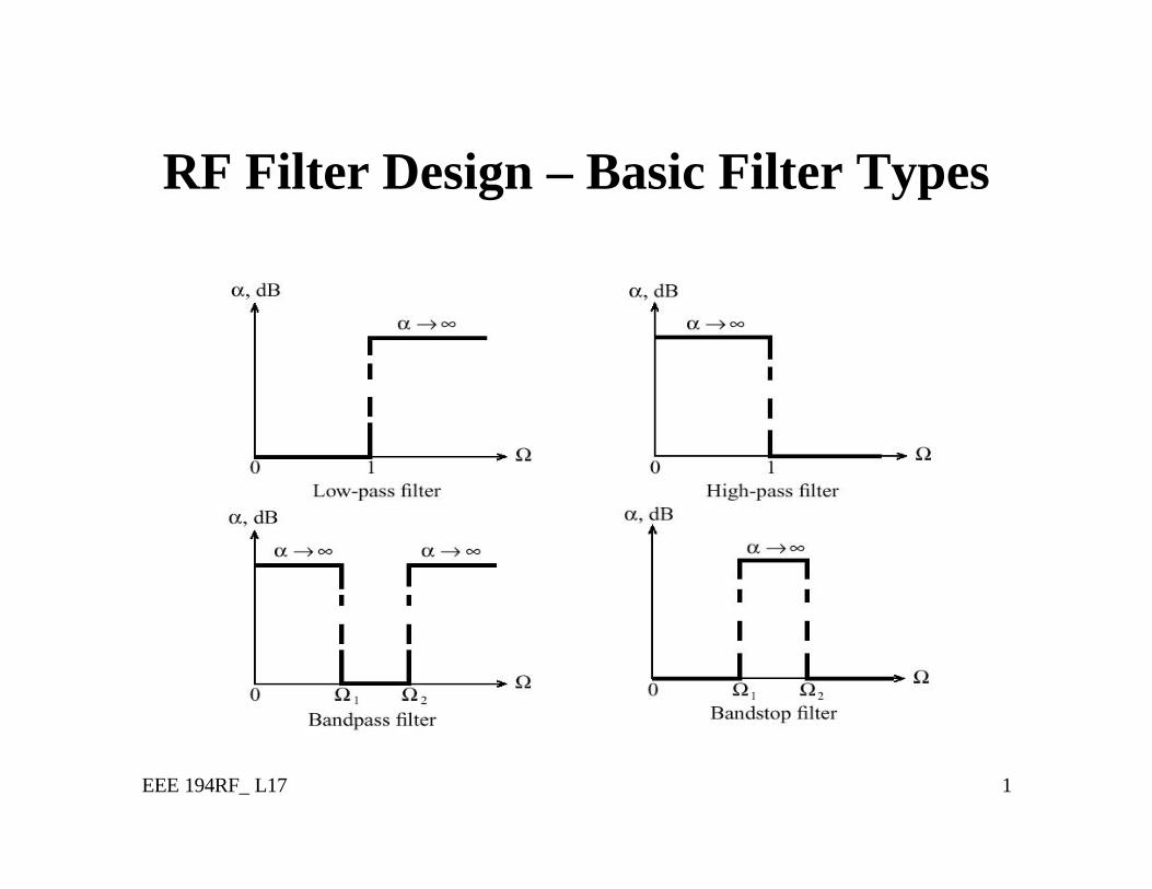
RF Filter Design – Basic Filter Types
EEE 194RF_ L17 2
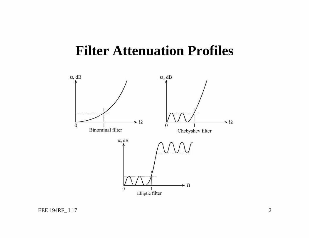
Filter Attenuation Profiles
EEE 194RF_ L17 3
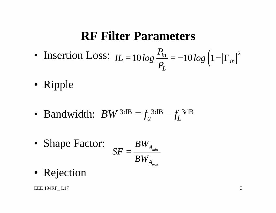
RF Filter Parameters• Insertion Loss:
• Ripple
• Bandwidth: BW 3dB = fu3dB – fL3dB
• Shape Factor:
• Rejection
( )210 10 1inin
L
PIL log log
P= = − − Γ
min
max
A
A
BWSF
BW=
EEE 194RF_ L17 4
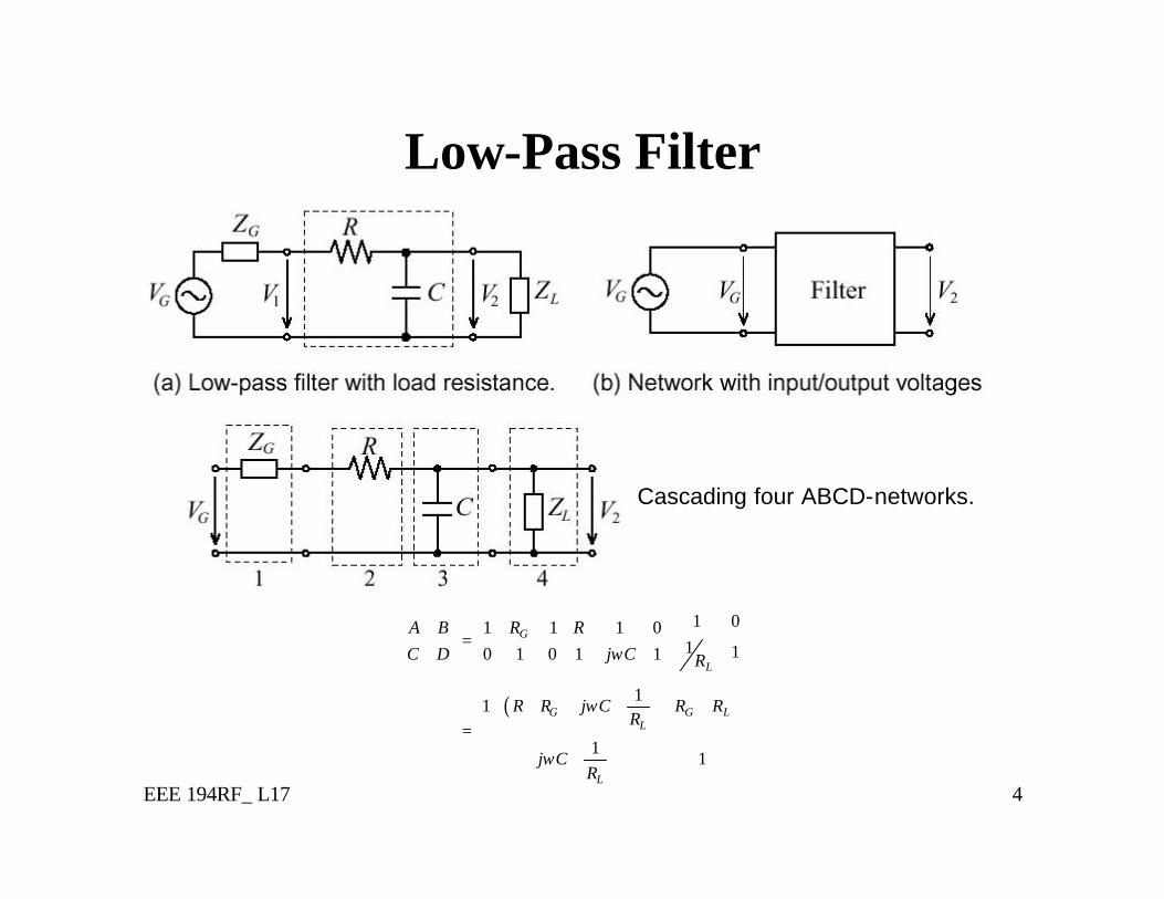
Low-Pass Filter
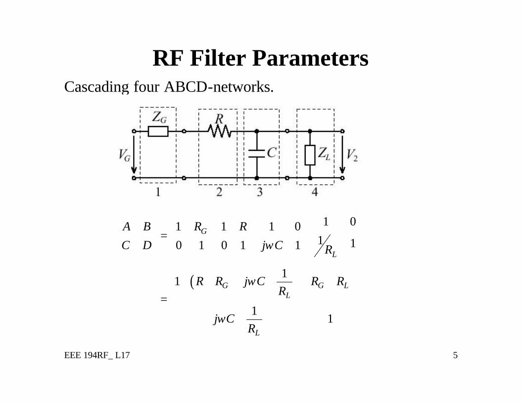
Cascading four ABCD-networks.
( )
1 01 1 1 01 10 1 0 1 1
11
11
G
L
G G LL
L
A B R RC D j C R
R R j C R RR
j CR
ω
ω
ω
=
+ + + + =
+
EEE 194RF_ L17 5
RF Filter Parameters
( )
1 01 1 1 01 10 1 0 1 1
11
11
G
L
G G LL
L
A B R RC D j C R
R R j C R RR
j CR
ω
ω
ω
=
+ + + + =
+
Cascading four ABCD-networks.
EEE 194RF_ L17 6
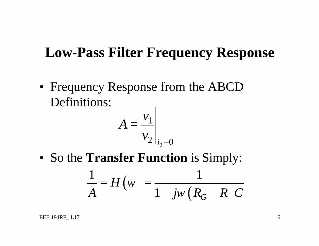
Low-Pass Filter Frequency Response
• Frequency Response from the ABCD Definitions:
• So the Transfer Function is Simply:2
1
2 0i
vA
v =
=
( ) ( )1 1
1 G
HA j R R C
ωω
= =+ +
EEE 194RF_ L17 7
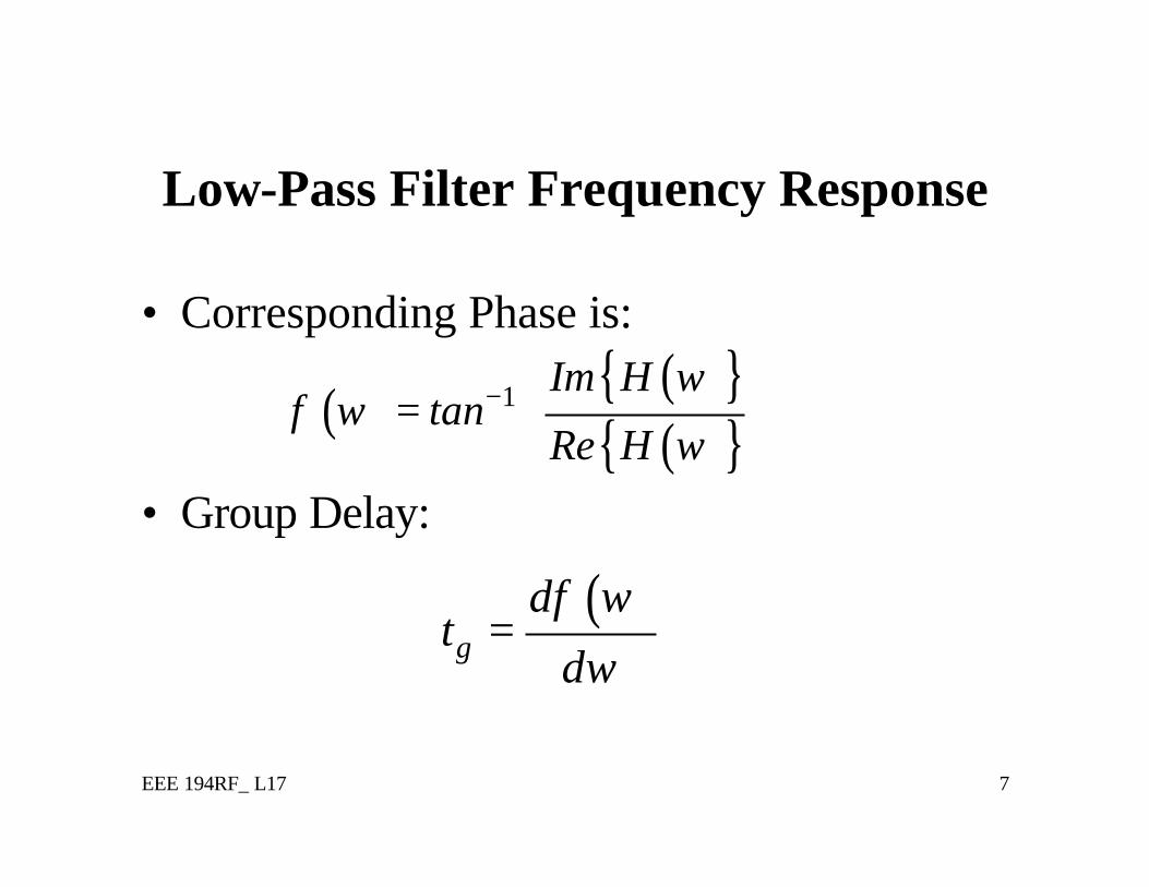
Low-Pass Filter Frequency Response
• Corresponding Phase is:
• Group Delay:
( )g
dt
d
φ ωω
=
( ) ( ){ }( ){ }
1 Im Htan
Re H
ωφ ω
ω−
=
EEE 194RF_ L17 8
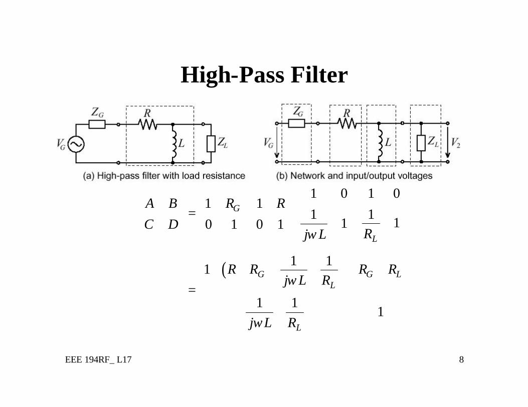
High-Pass Filter
( )
1 01 01 1
11 110 1 0 1
1 11
1 11
G
L
G G LL
L
A B R RC D
Rj L
R R R Rj L R
j L R
ω
ω
ω
=
+ + + +
= +
EEE 194RF_ L17 9
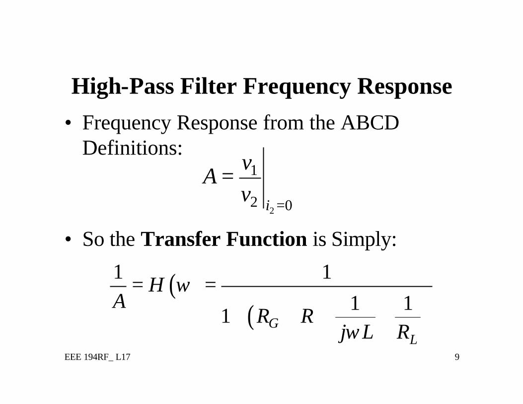
High-Pass Filter Frequency Response• Frequency Response from the ABCD
Definitions:
• So the Transfer Function is Simply:2
1
2 0i
vA
v =
=
( )( )
1 11 1
1 GL
HA
R Rj L R
ω
ω
= =
+ + +
EEE 194RF_ L17 10
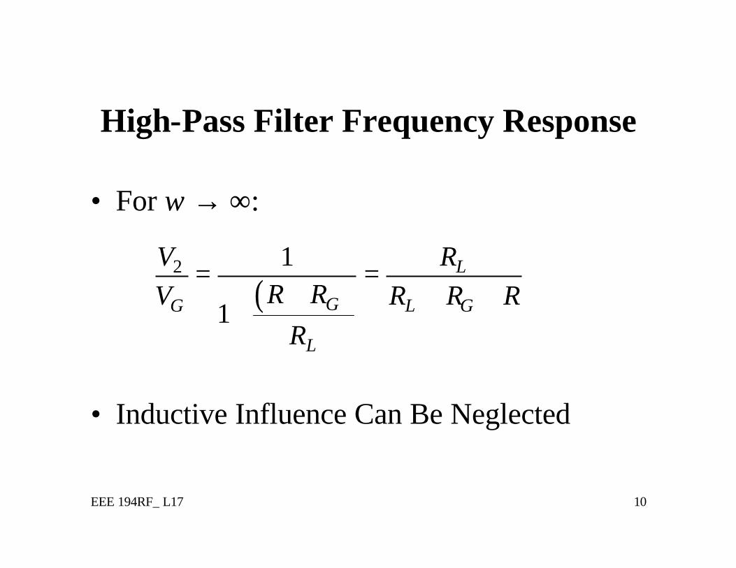
High-Pass Filter Frequency Response
• For ω → ∞:
• Inductive Influence Can Be Neglected
( )2 1
1
L
GG L G
L
V RR RV R R R
R
= =+ + +
+
EEE 194RF_ L17 11
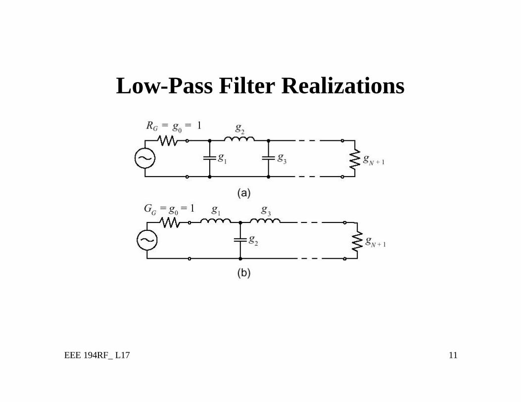
Low-Pass Filter Realizations
EEE 194RF_ L17 12
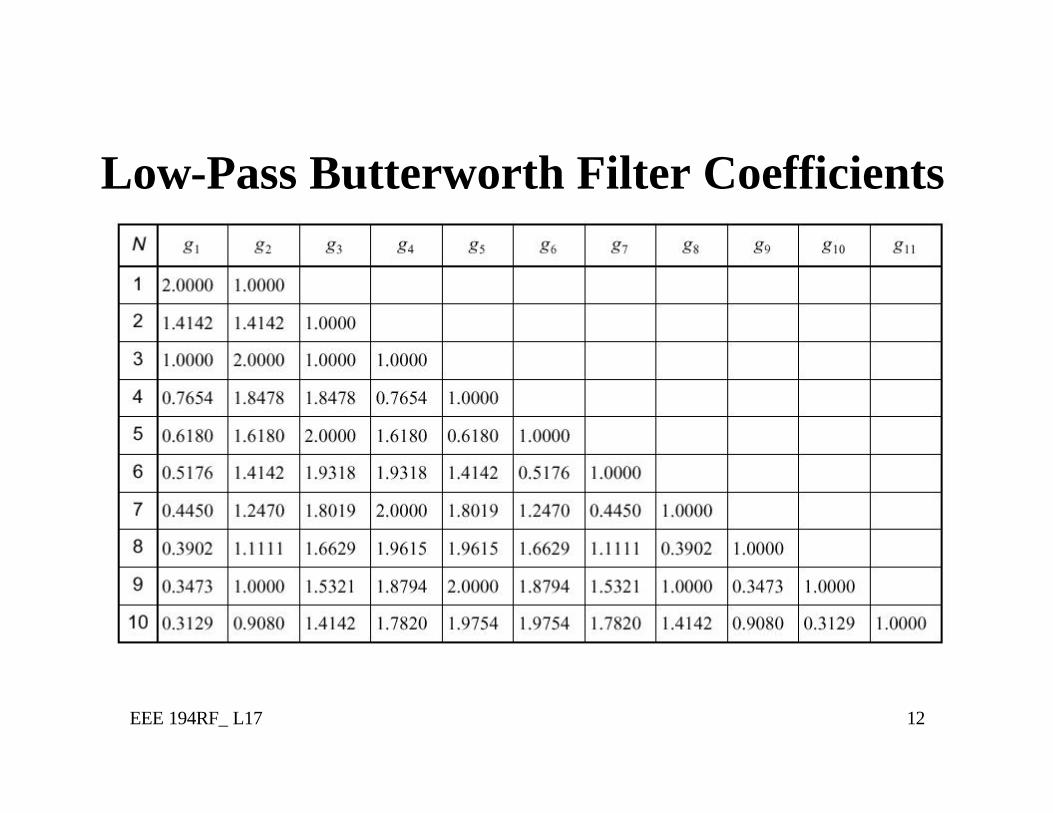
Low-Pass Butterworth Filter Coefficients
EEE 194RF_ L17 13
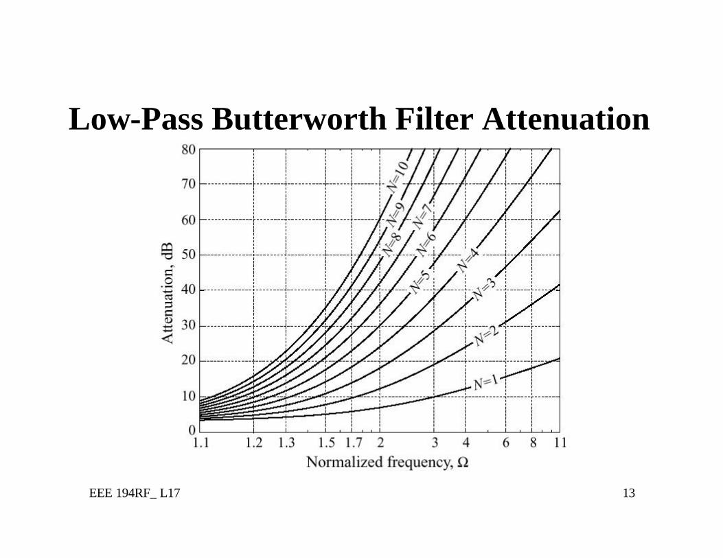
Low-Pass Butterworth Filter Attenuation
EEE 194RF_ L17 14
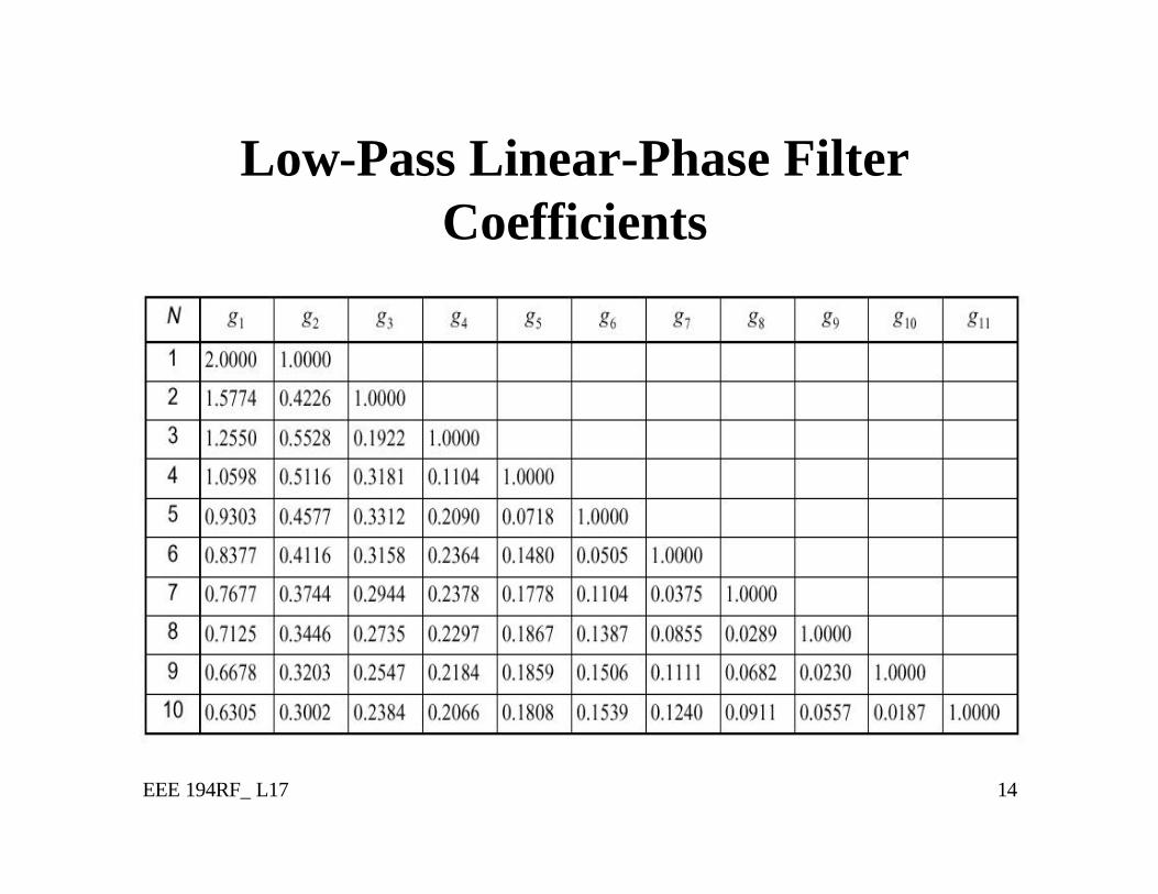
Low-Pass Linear-Phase Filter Coefficients
EEE 194RF_ L17 15
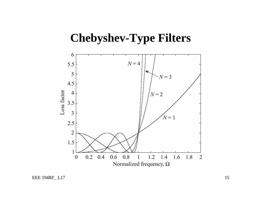
Chebyshev-Type Filters
EEE 194RF_ L17 16
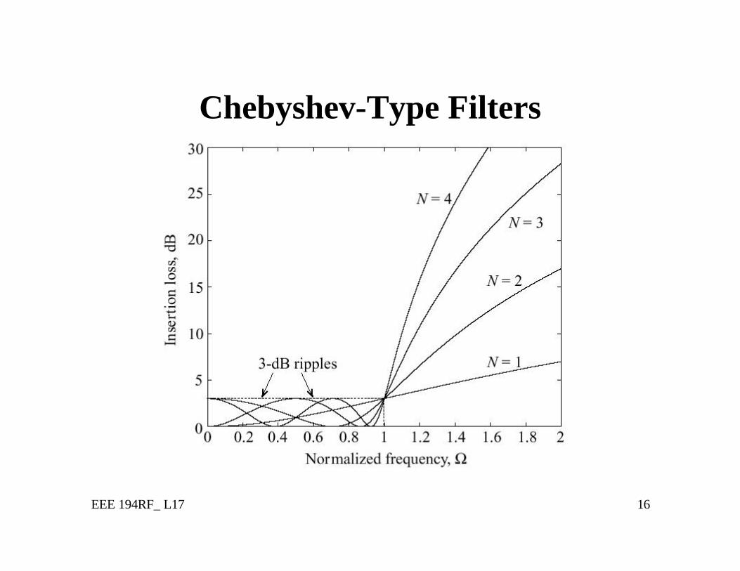
Chebyshev-Type Filters
EEE 194RF_ L17 17
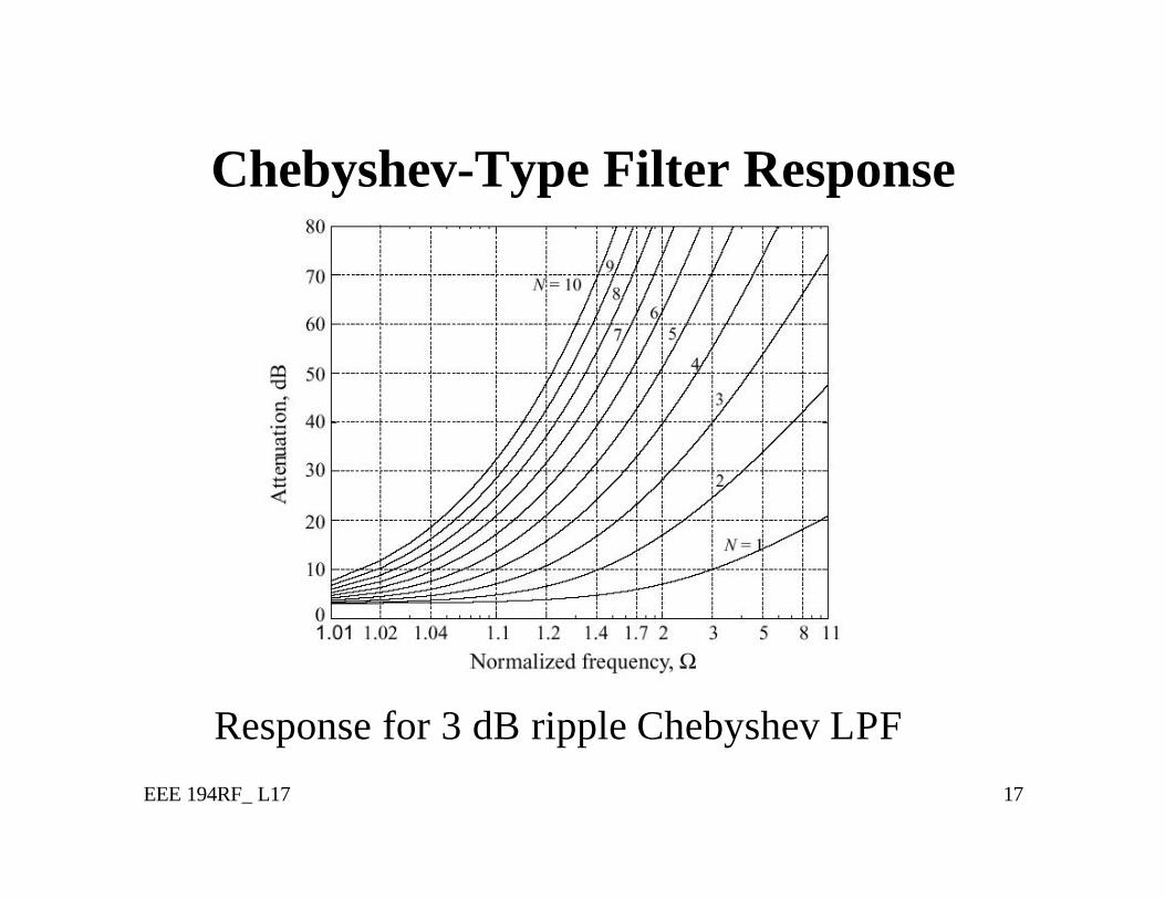
Chebyshev-Type Filter Response
Response for 3 dB ripple Chebyshev LPF
EEE 194RF_ L17 18
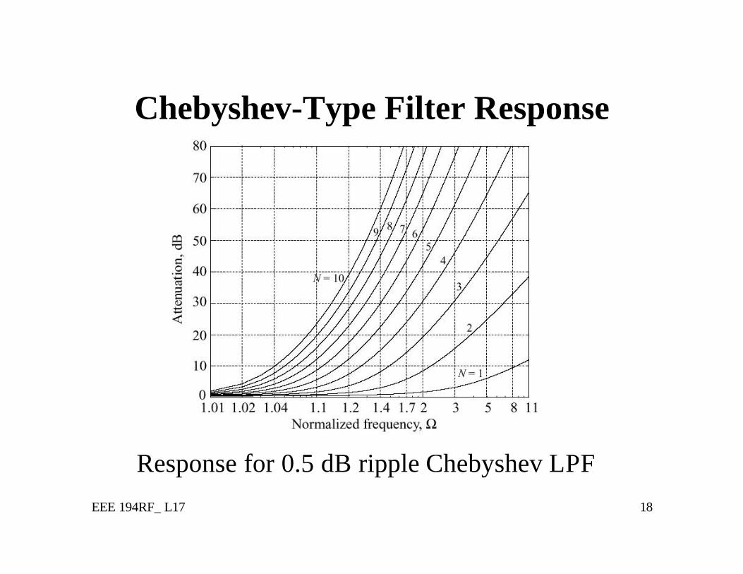
Chebyshev-Type Filter Response
Response for 0.5 dB ripple Chebyshev LPF
EEE 194RF_ L17 19
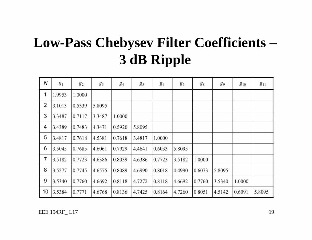
Low-Pass Chebysev Filter Coefficients –3 dB Ripple
EEE 194RF_ L17 20
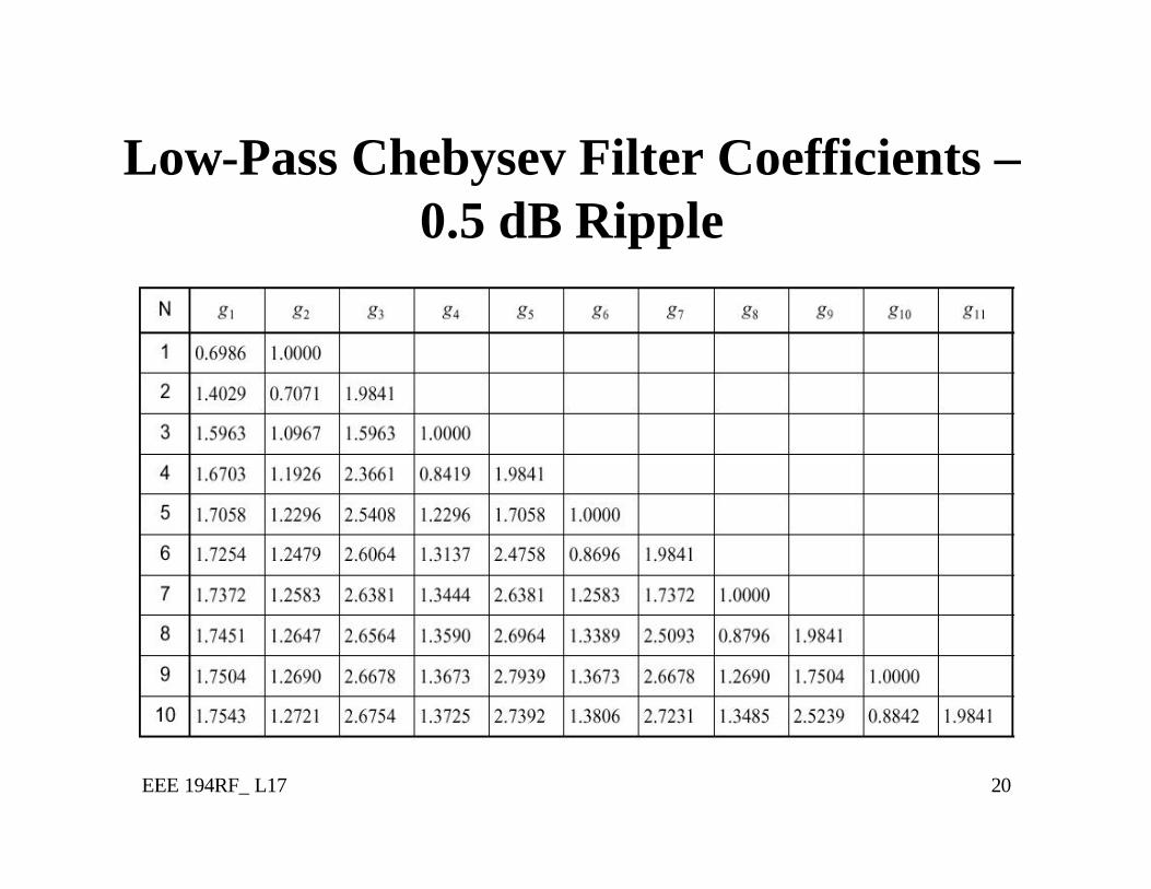
Low-Pass Chebysev Filter Coefficients –0.5 dB Ripple
EEE 194RF_ L17 21
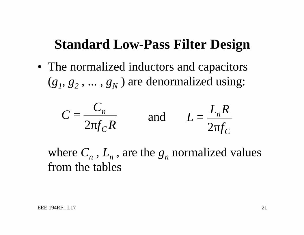
Standard Low-Pass Filter Design
• The normalized inductors and capacitors (g1, g2 , ... , gN ) are denormalized using:
and
where Cn , Ln , are the gn normalized values from the tables
2n
C
CC
f R=
π 2n
C
L RL
f=
π
Top Related