


γλώσσες
Σελίδες
Νομικός

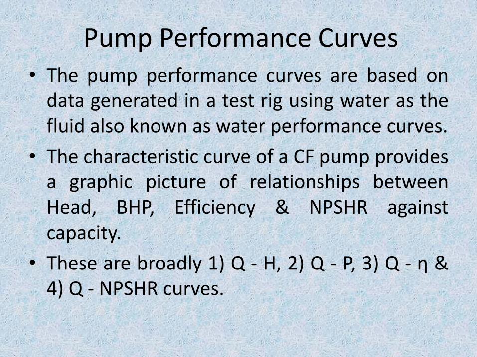
Pump Performance Curves• The pump performance curves are based on
data generated in a test rig using water as thefluid also known as water performance curves.
• The characteristic curve of a CF pump providesa graphic picture of relationships betweenHead, BHP, Efficiency & NPSHR againstcapacity.
• These are broadly 1) Q - H, 2) Q - P, 3) Q - η &4) Q - NPSHR curves.
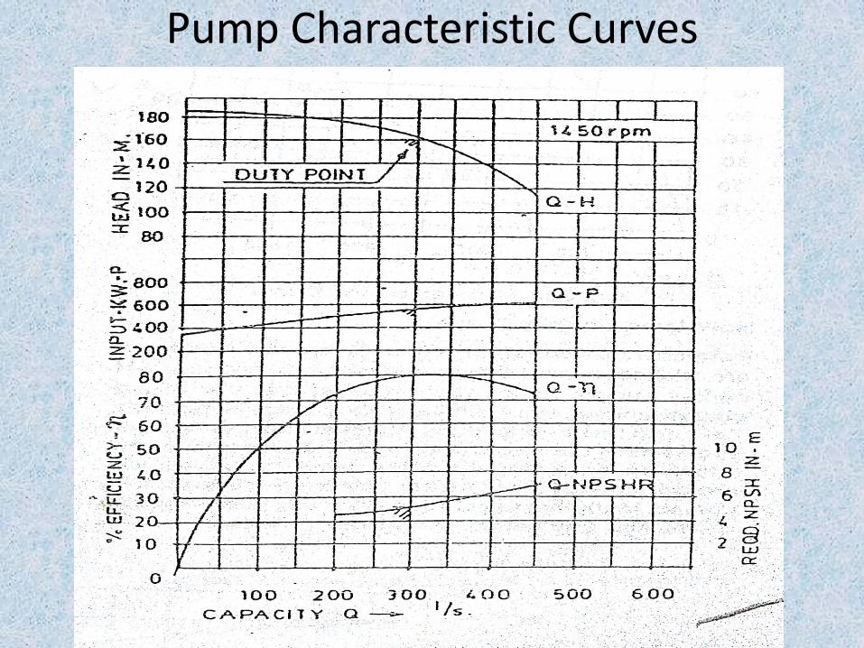
Pump Characteristic Curves
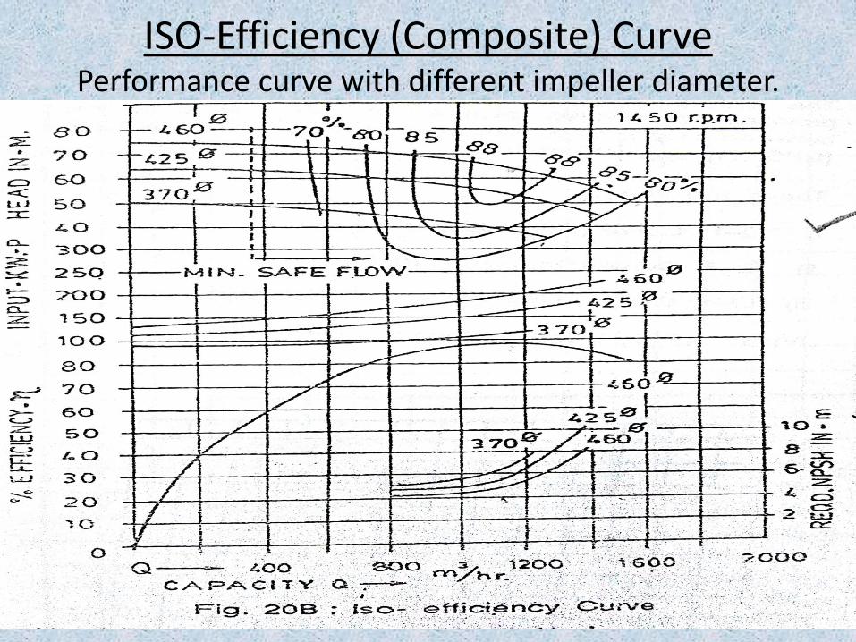
ISO-Efficiency (Composite) CurvePerformance curve with different impeller diameter.
Shut off Head & Cut-off Point Definition
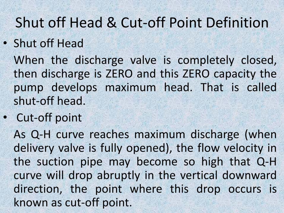
• Shut off Head
When the discharge valve is completely closed,then discharge is ZERO and this ZERO capacity thepump develops maximum head. That is calledshut-off head.
• Cut-off point
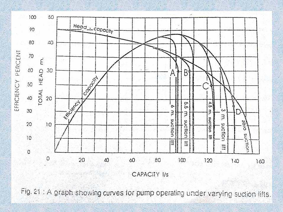
As Q-H curve reaches maximum discharge (whendelivery valve is fully opened), the flow velocity inthe suction pipe may become so high that Q-Hcurve will drop abruptly in the vertical downwarddirection, the point where this drop occurs isknown as cut-off point.
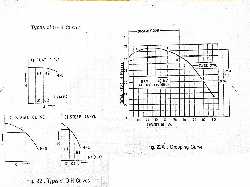
Types of Q vs. H Curves
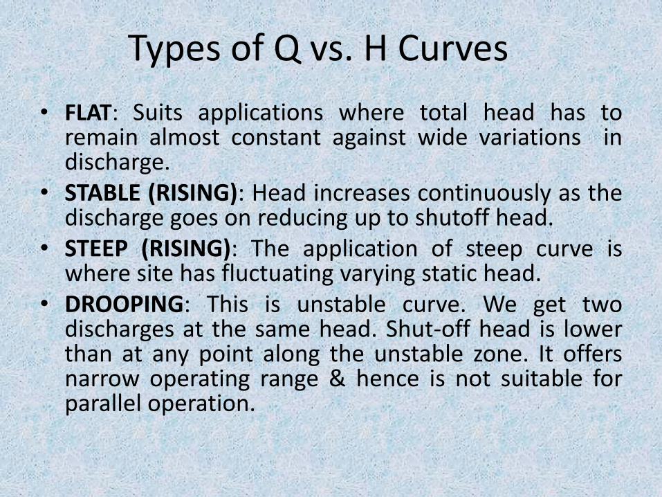
• FLAT: Suits applications where total head has toremain almost constant against wide variations indischarge.
• STABLE (RISING): Head increases continuously as thedischarge goes on reducing up to shutoff head.
• STEEP (RISING): The application of steep curve iswhere site has fluctuating varying static head.
• DROOPING: This is unstable curve. We get twodischarges at the same head. Shut-off head is lowerthan at any point along the unstable zone. It offersnarrow operating range & hence is not suitable forparallel operation.
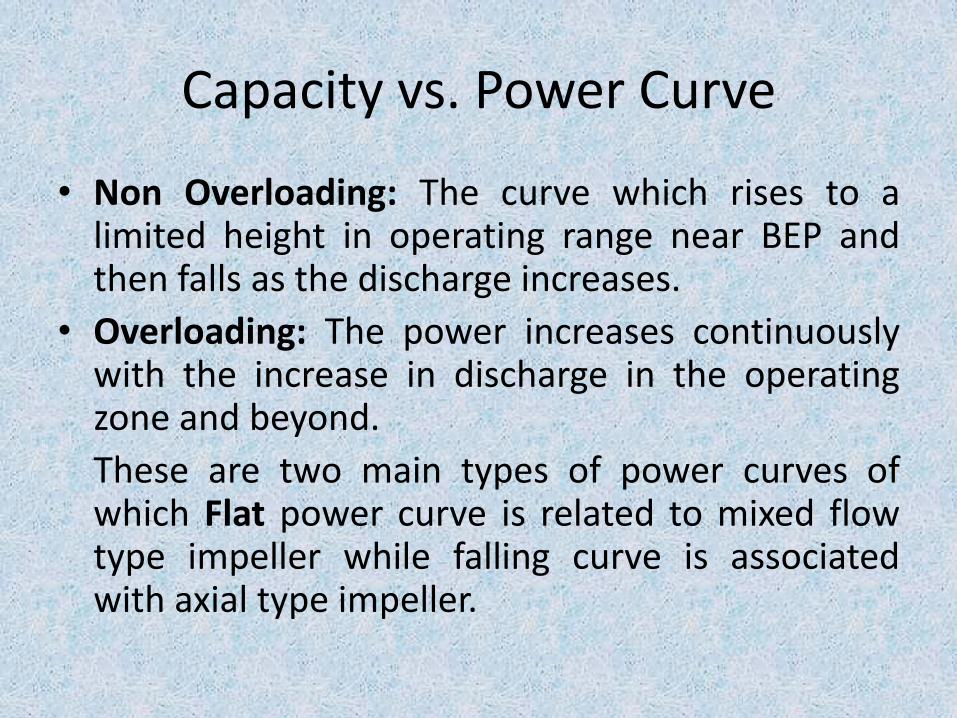
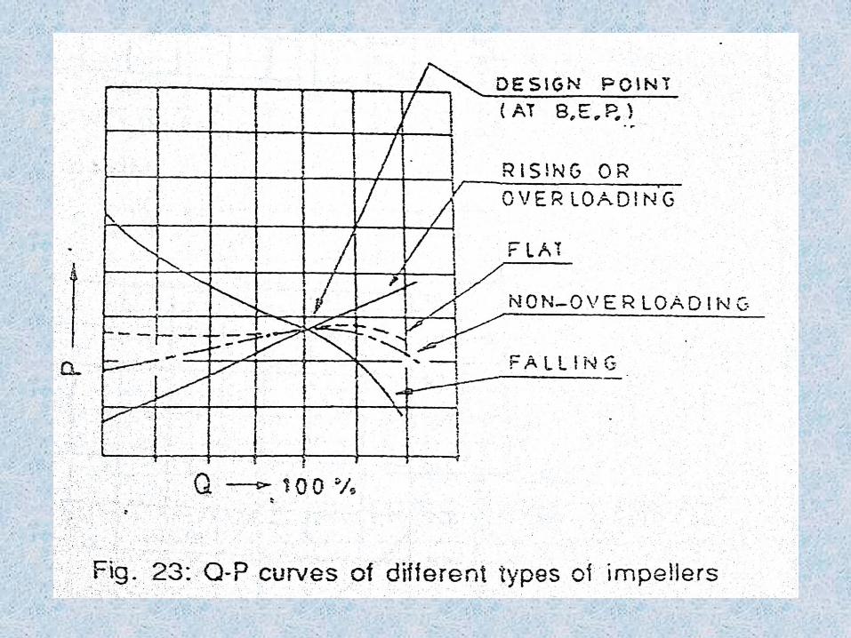
Capacity vs. Power Curve
• Non Overloading: The curve which rises to alimited height in operating range near BEP andthen falls as the discharge increases.
• Overloading: The power increases continuouslywith the increase in discharge in the operatingzone and beyond.
These are two main types of power curves ofwhich Flat power curve is related to mixed flowtype impeller while falling curve is associatedwith axial type impeller.
Impellers (Geometry)• Types of Impellers & performance curves have a
close relation.
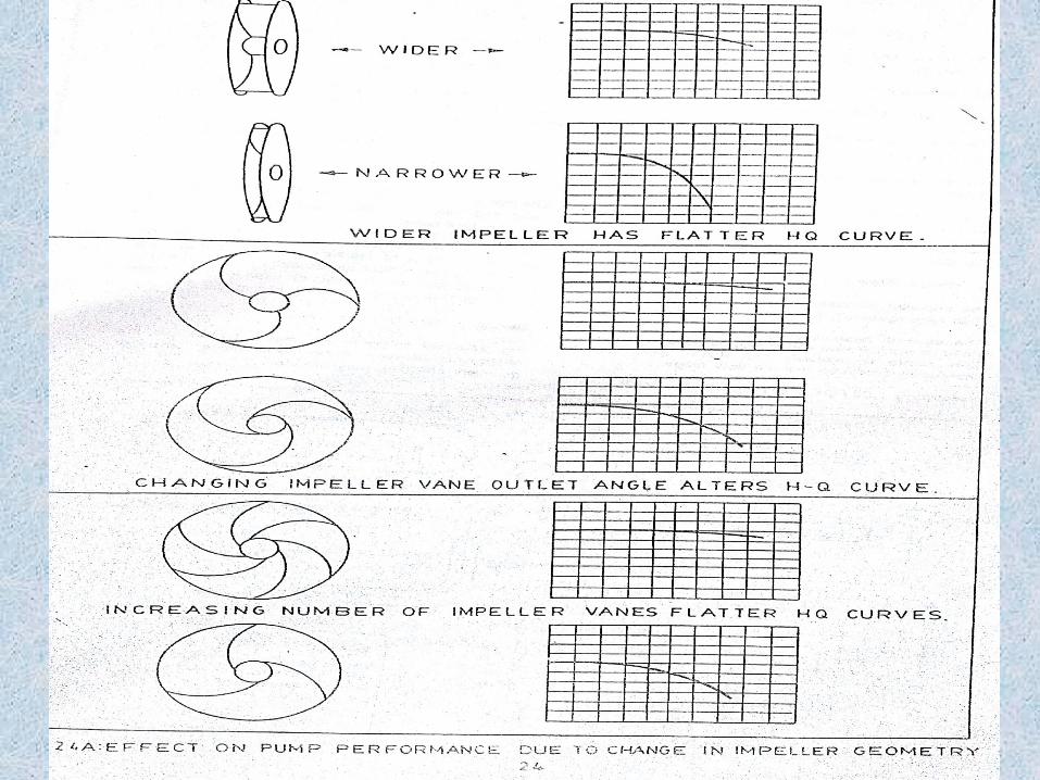
• Impeller Geometry: For each type basic dimensionsof impellers are different:
1) Ratio of impeller outside (outlet) diameter to eye(inlet) diameter i. e. D 2 / D 1 and
2) Outlet width
• Further impeller vane outlet angle , inlet angle & outletfinishing will also affect Q-H curves & NPSHR.
• Figure illustrates the relationship between pumpperformance, impeller geometry & vane numbers.
Continued
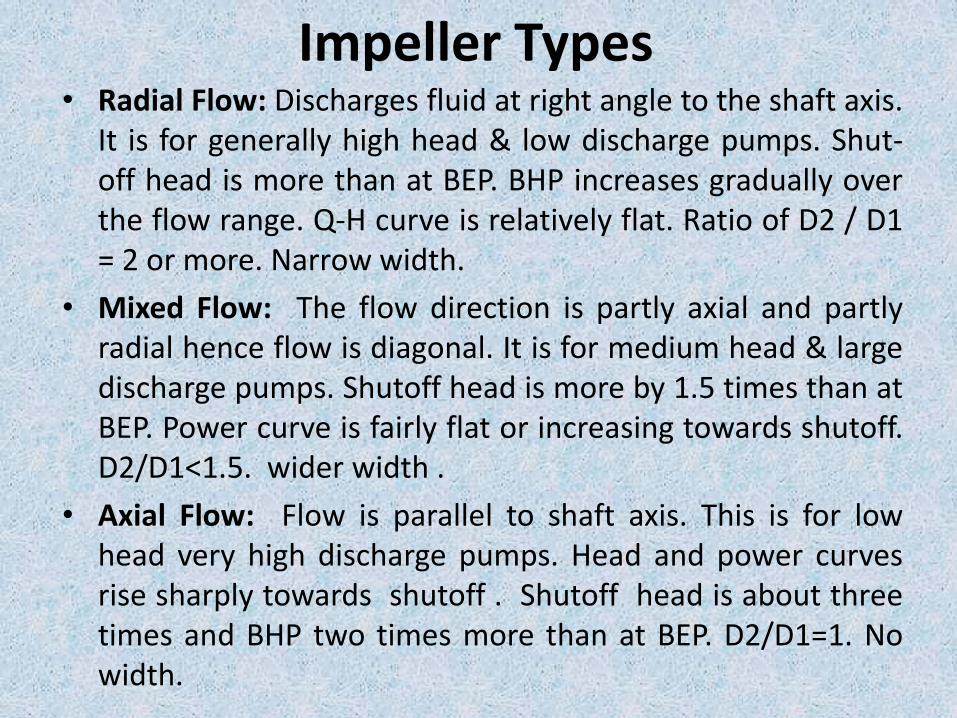
Impeller Types• Radial Flow: Discharges fluid at right angle to the shaft axis.
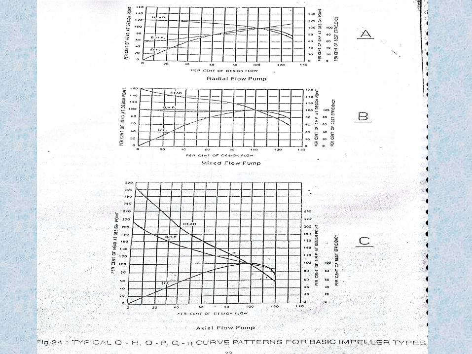
It is for generally high head & low discharge pumps. Shut-off head is more than at BEP. BHP increases gradually overthe flow range. Q-H curve is relatively flat. Ratio of D2 / D1= 2 or more. Narrow width.
• Mixed Flow: The flow direction is partly axial and partlyradial hence flow is diagonal. It is for medium head & largedischarge pumps. Shutoff head is more by 1.5 times than atBEP. Power curve is fairly flat or increasing towards shutoff.D2/D1<1.5. wider width .
• Axial Flow: Flow is parallel to shaft axis. This is for lowhead very high discharge pumps. Head and power curvesrise sharply towards shutoff . Shutoff head is about threetimes and BHP two times more than at BEP. D2/D1=1. Nowidth.
Power & Efficiency of Pump • The work performed by the pump is equal to the liquid
pumped (l/s) in unit time x total head (meters).
• Pump Output (WHP): Water Horse Power
• Pump Input (BHP): Brake Horse Power
• Pump Efficiency: η = (WHP/ BHP) x 100
• The brake horse power is greater than hydraulic horse powerdue to the mechanical & hydraulic losses incurred in thepump.
• A pump’s power demand is directly proportional to thedifference between the inlet & outlet pressure & the flowrate.
• Suitable prime mover i. e. motor is to be selected consideringefficiency of pump & its full operational range.
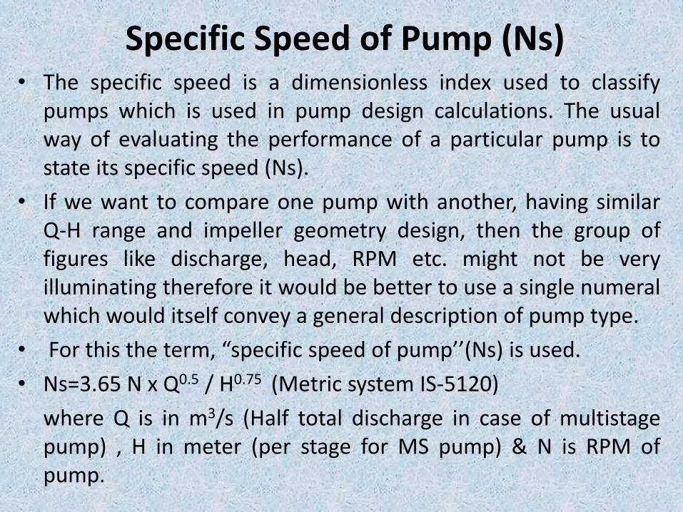
Specific Speed of Pump (Ns)• The specific speed is a dimensionless index used to classify
pumps which is used in pump design calculations. The usualway of evaluating the performance of a particular pump is tostate its specific speed (Ns).
• If we want to compare one pump with another, having similarQ-H range and impeller geometry design, then the group offigures like discharge, head, RPM etc. might not be veryilluminating therefore it would be better to use a single numeralwhich would itself convey a general description of pump type.
• For this the term, “specific speed of pump’’(Ns) is used.
• Ns=3.65 N x Q0.5 / H0.75 (Metric system IS-5120)
where Q is in m3/s (Half total discharge in case of multistagepump) , H in meter (per stage for MS pump) & N is RPM ofpump.
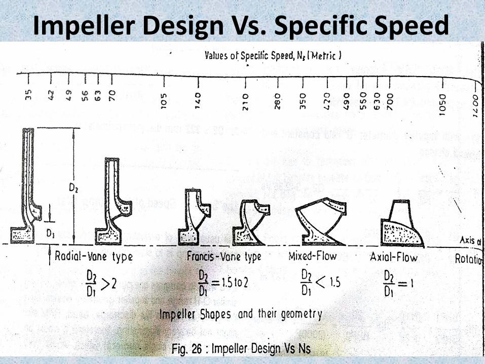
Impeller Design Vs. Specific Speed
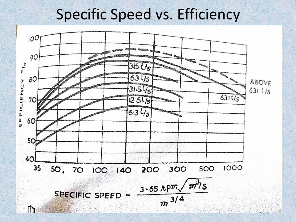
Specific Speed vs. Efficiency
Affinity Laws
• These are derived from a dimensionlessanalysis of three parameters that describepump performance: flow, total head & power.
• The analysis is based on the reduced impellerbeing geometrically similar & operated atdynamically similar conditions or equalspecific speed.
• The affinity laws were developed using thelaw of similitude which provide three basicrelationships viz. Flow, Total Head & Power vs.Diameter & Speed. Continued
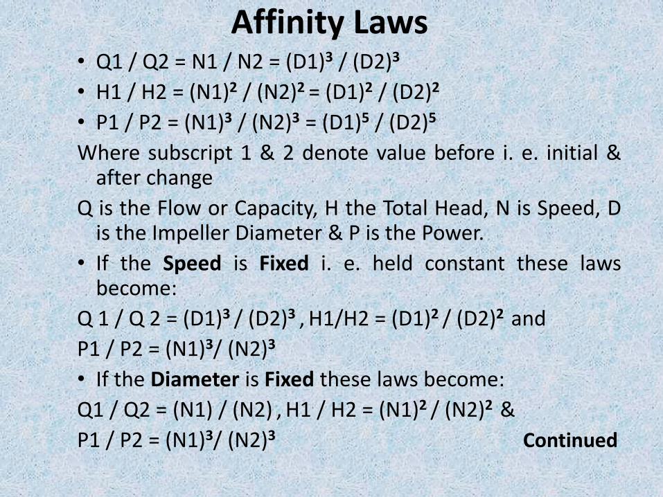
Affinity Laws• Q1 / Q2 = N1 / N2 = (D1)3 / (D2)3
• H1 / H2 = (N1)2 / (N2)2 = (D1)2 / (D2)2
• P1 / P2 = (N1)3 / (N2)3 = (D1)5 / (D2)5
Where subscript 1 & 2 denote value before i. e. initial &after change
Q is the Flow or Capacity, H the Total Head, N is Speed, Dis the Impeller Diameter & P is the Power.
• If the Speed is Fixed i. e. held constant these lawsbecome:
Q 1 / Q 2 = (D1)3 / (D2)3 , H1/H2 = (D1)2 / (D2)2 and
P1 / P2 = (N1)3/ (N2)3
• If the Diameter is Fixed these laws become:
Q1 / Q2 = (N1) / (N2) , H1 / H2 = (N1)2 / (N2)2 &
P1 / P2 = (N1)3/ (N2)3 Continued
Affinity Laws• If the actual speed is more than the nominal than
power input as well as NPSHr will also be more, insuch a situation we can check for actual powerand NPSHr with the help of affinity formula andensure in respect of motor overloading andcavitation.
• If the actual operating head is much lower thanrated head, pump will operate at excessive flowresulting in overloading the motor. In such caseimpeller diameter needs to be trimmed to suitthe operating conditions. However this will resultin reduction of the efficiency of the pump.
Cavitation• The lowest pressure point in a pump occurs at the
inlet of the pump impeller. If the pressure at anypoint inside the pump drops below the vapourpressure of liquid, then liquid may evaporategenerating small vapour bubbles i. e. the liquidflashes i.e. changing from liquid to gaseous phase.The vapour bubbles are carried along with thestream through the impeller eye to regions wherethe pressure within the impeller shroud rises due tocentrifugal force. In the higher pressure zone thebubbles implode with tremendous shock and noise.This phenomenon is called cavitations. Continued
Cavitation• To counter the situation of cavitation,
adequate suction head shall be provided sothat suction pressure at the impeller eye willremain above the liquid vapour pressure.Alternatively to reduce the discharge to bareminimum and thus reduce the NPSHR. Onecan reduce the speed and thus reducing thedischarge the NPSHR value will also getreduced.
• Cavitation can occur at any point on the curveif NPSHR is less than NPSHR.
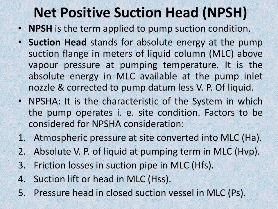
Net Positive Suction Head (NPSH)• NPSH is the term applied to pump suction condition.
• Suction Head stands for absolute energy at the pumpsuction flange in meters of liquid column (MLC) abovevapour pressure at pumping temperature. It is theabsolute energy in MLC available at the pump inletnozzle & corrected to pump datum less V. P. Of liquid.
• NPSHA: It is the characteristic of the System in whichthe pump operates i. e. site condition. Factors to beconsidered for NPSHA consideration:
1. Atmospheric pressure at site converted into MLC (Ha).
2. Absolute V. P. of liquid at pumping term in MLC (Hvp).
3. Friction losses in suction pipe in MLC (Hfs).
4. Suction lift or head in MLC (Hss).
5. Pressure head in closed suction vessel in MLC (Ps).
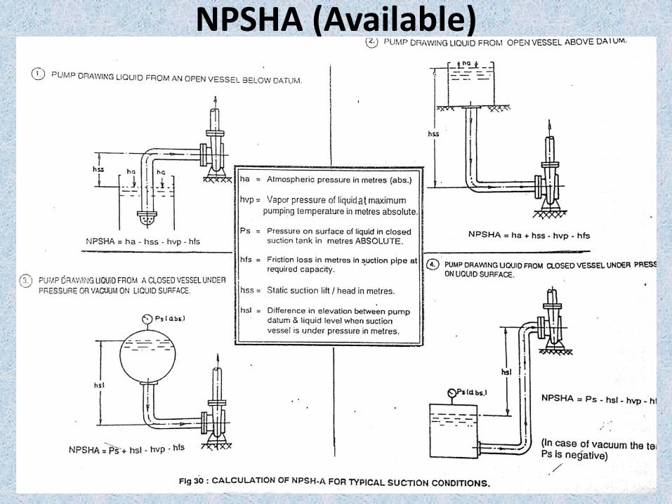
NPSHA (Available)
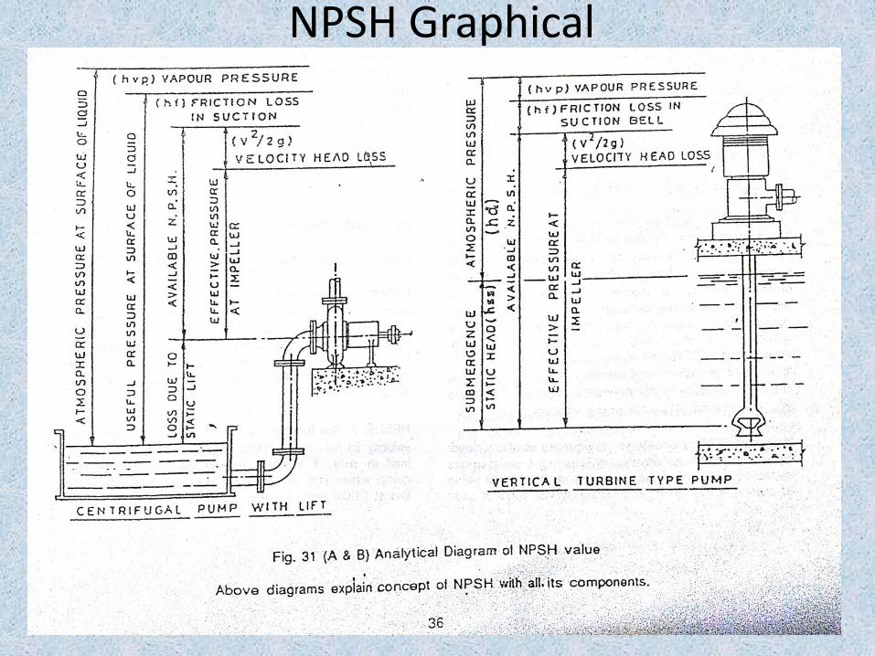
NPSH Graphical
NPSHR (Required)• NPSHR is defined as the positive head in metres
absolutely necessary at the impeller eye to overcomethe Internal Pressure Drop within the impeller andmaintain the pressure above its vapour pressure andthus ensure stable flow into the impeller. The pumpdesigner decides the NPSHR value of the pumpmodel.
• It is the function of the impeller eye peripheralvelocity in m/s & suction velocity of liquid at pumpinlet in m/s.
• NPSHR must always be greater than NPSHA (at least0.5 m).
• Vapour pressure of liquid is dependent oftemperature & will rise with increasing temperature.
Parallel pump operation
• Parallel operation means connecting two ormore pumps to common discharge headeroutlet with necessary fittings like sluice /butterfly and check valves. Additional pumpsare put to the service if demand increasesand vice versa. The working is absolutelyflexible, since this method increasesdischarge at the same head.
Points to be observed before selecting pump for parallel operation
1. Selecting identical pumps as far as possiblewith stable Q-H characteristic (for equal loadon each pump. This also keeps the spare partinventory to an economic level).
2. Pumps of dissimilar characteristics canoperate in parallel, if the system head doesnot exceed the shut off head of any of thepump at any capacity.
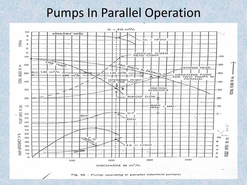
Pumps In Parallel Operation

THANKS
Top Related