


γλώσσες
Σελίδες
Νομικός

PROBLEM 8.1
KNOWN: Flowrate and temperature of water in fully developed flow through a tube of prescribeddiameter.
FIND: Maximum velocity and pressure gradient.
SCHEMATIC:
ASSUMPTIONS: (1) Steady-state conditions, (2) Isothermal flow.
PROPERTIES: Table A-6, Water (300K): ρ = 998 kg/m3, µ = 855 × 10
-6 N⋅s/m2
.
ANALYSIS: From Eq. 8.6,
( )D 64m 4 0.01 kg/s
Re 596.D 0.025m 855 10 kg m/sπ µ π −
×= = =
× ⋅
&
Hence the flow is laminar and the velocity profile is given by Eq. 8.15,
( ) ( )2om
u r2 1 r/r .
u = −
The maximum velocity is therefore at r = 0, the centerline, where
( ) mu 0 2 u .=
From Eq. 8.5
( )m 2 23
m 4 0.01 kg/su 0.020 m/s,
D / 4 998 kg/m 0.025mρπ π
×= = =×
&
hence
( )u 0 0.041 m/s.=
Combining Eqs. 8.16 and 8.19, the pressure gradient is
2m
D
dp 64 u
dx Re 2Dρ= −
( )232 2998 kg/m 0.020 m/sdp 64
0.86 kg/m sdx 596 2 0.025 m
= − × = − ⋅×
2 -5dp0.86N/m m 0.86 10 bar/m.
dx= − ⋅ = − × <
PROBLEM 8.2
KNOWN: Temperature and mean velocity of water flow through a cast iron pipe of prescribedlength and diameter.
FIND: Pressure drop.
SCHEMATIC:
ASSUMPTIONS: (1) Steady-state conditions, (2) Fully developed flow, (3) Constant properties.
PROPERTIES: Table A-6, Water (300K): ρ = 997 kg/m3, µ = 855 × 10
-6 N⋅s/m2
.
ANALYSIS: From Eq. 8.22, the pressure drop is
2m u
p f L.2D
ρ∆ =
With
34m
D -6 2 u D 997 kg/m 0.2 m/s 0.15 m
Re 3.50 10855 10 N s/m
ρµ
× ×= = = ×× ⋅
the flow is turbulent and with e = 2.6 ×10⁻⁴
m for cast iron (see Fig. 8.3), it follows that e/D = 1.73
× 10-3
and
f 0.027.≈
Hence,
( ) ( )23997 kg/m 0.2 m/s
p 0.027 600m2 0.15 m
∆ =×
2 2p 2154 kg/s m 2154 N/m∆ = ⋅ =
p 0.0215 bar.∆ = <COMMENTS: For the prescribed geometry, L/D = (600/0.15) = 4000 >> (xfd,h/D)turb ≈ 10,and the assumption of fully developed flow throughout the pipe is justified.
PROBLEM 8.3
KNOWN: Temperature and velocity of water flow in a pipe of prescribed dimensions.
FIND: Pressure drop and pump power requirement for (a) a smooth pipe, (b) a cast iron pipe with aclean surface, and (c) smooth pipe for a range of mean velocities 0.05 to 1.5 m/s.
SCHEMATIC:
ASSUMPTIONS: (1) Steady, fully developed flow.
PROPERTIES: Table A.6, Water (300 K): ρ = 997 kg/m3, µ = 855 × 10-6 N⋅s/m2, ν = µ/ρ = 8.576 ×10⁻⁷ m2/s.
ANALYSIS: From Eq. 8.22a and 8.22b, the pressure drop and pump power requirement are2mu
p f L2D
ρ∆ = ( )2mP pV p D 4 uπ= ∆ = ∆� (1,2)
The friction factor, f, may be determined from Figure 8.3 for different relative roughness, e/D, surfacesor from Eq. 8.21 for the smooth condition, 3000 ≤ ReD ≤ 5 × 10⁶,
( )( ) 2Df 0.790ln Re 1.64
−= − (3)
where the Reynolds number is
5mD 7 2
u D 1m s 0.25mRe 2.915 10
8.576 10 m sν −×= = = ×
×(4)
(a) Smooth surface: from Eqs. (3), (1) and (2),
( )( ) 25f 0.790ln 2.915 10 1.64 0.01451−
= × − =
( )3 2 2 4 2p 0.01451 997 kg m 1m s 2 0.25m 1000 m 2.89 10 kg s m∆ = × × = × ⋅ = 0 289. bar <
( )4 2 2 2P 2.89 10 N m 0.25 m 4 1m s 1418 N m s 1.42 kWπ= × × = ⋅ = <(b) Cast iron clean surface: with e = 260 µm, the relative roughness is e/D = 260 × 10-6 m/0.25 m = 1.04× 10⁻³. From Figure 8.3 with ReD = 2.92 × 10⁵, find f = 0.021. Hence,
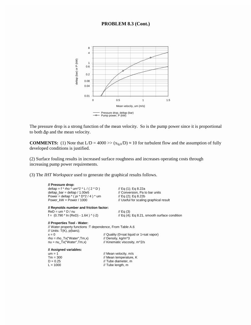
∆p = 0.419 bar P = 2.06 kW <(c) Smooth surface: Using IHT with the expressions of part (a), the pressure drop and pump powerrequirement as a function of mean velocity, um, for the range 0.05 ≤ um ≤ 1.5 m/s are computed andplotted below.
Continued...
PROBLEM 8.3 (Cont.)
0 0.5 1 1.5
Mean velocity, um (m/s)
0.01
0.04
0.08
0.2
0.61
4
8
delta
p (b
ar)
or P
(kW
)
Pressure drop, deltap (bar)Pump power, P (kW)
The pressure drop is a strong function of the mean velocity. So is the pump power since it is proportionalto both ∆p and the mean velocity.
COMMENTS: (1) Note that L/D = 4000 >> (xfg,h/D) ≈ 10 for turbulent flow and the assumption of fullydeveloped conditions is justified.
(2) Surface fouling results in increased surface roughness and increases operating costs throughincreasing pump power requirements.
(3) The IHT Workspace used to generate the graphical results follows.
// Pressure drop:deltap = f * rho * um^2 * L / ( 2 * D ) // Eq (1); Eq 8.22adeltap_bar = deltap / 1.00e5 // Conversion, Pa to bar unitsPower = deltap * ( pi * D^2 / 4 ) * um // Eq (2); Eq 8.22bPower_kW = Power / 1000 // Useful for scaling graphical result
// Reynolds number and friction factor:ReD = um * D / nu // Eq (3)f = (0.790 * ln (ReD) - 1.64 ) ^ (-2) // Eq (4); Eq 8.21, smooth surface condition
// Properties Tool - Water:// Water property functions :T dependence, From Table A.6// Units: T(K), p(bars);x = 0 // Quality (0=sat liquid or 1=sat vapor)rho = rho_Tx("Water",Tm,x) // Density, kg/m^3nu = nu_Tx("Water",Tm,x) // Kinematic viscosity, m^2/s
// Assigned variables:um = 1 // Mean velocity, m/sTm = 300 // Mean temperature, KD = 0.25 // Tube diameter, mL = 1000 // Tube length, m
PROBLEM 8.4
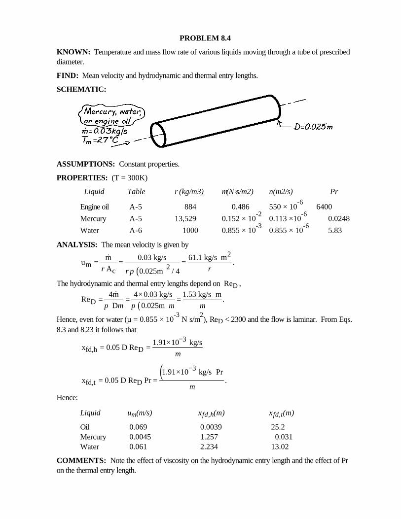
KNOWN: Temperature and mass flow rate of various liquids moving through a tube of prescribeddiameter.
FIND: Mean velocity and hydrodynamic and thermal entry lengths.
SCHEMATIC:
ASSUMPTIONS: Constant properties.
PROPERTIES: (T = 300K)
Liquid Table ρ(kg/m3) µ(N⋅s/m2) ν(m2/s) Pr
Engine oil A-5 884 0.486 550 × 10-6
6400
Mercury A-5 13,529 0.152 × 10⁻²
0.113 ×10⁻⁶
0.0248
Water A-6 1000 0.855 × 10⁻³
0.855 × 10⁻⁶
5.83
ANALYSIS: The mean velocity is given by
( )
2m 2c
m 0.03 kg/s 61.1 kg/s mu .
A 0.025m / 4ρ ρρπ
⋅= = =&
The hydrodynamic and thermal entry lengths depend on ReD ,
( )D4m 4 0.03 kg/s 1.53 kg/s m
Re . D 0.025mπ µ π µ µ
× ⋅= = =
&
Hence, even for water (µ = 0.855 × 10⁻³
N⋅s/m2), ReD < 2300 and the flow is laminar. From Eqs.
8.3 and 8.23 it follows that3
fd,h D1.91 10 kg/s
x 0.05 D Reµ
−×= =
( )3
fd,t D1.91 10 kg/s Pr
x 0.05 D Re Pr .µ
−×= =
Hence:
Liquid um(m/s) xfd,h(m) xfd,t(m)
Oil 0.069 0.0039 25.2Mercury 0.0045 1.257 0.031Water 0.061 2.234 13.02
COMMENTS: Note the effect of viscosity on the hydrodynamic entry length and the effect of Pron the thermal entry length.
PROBLEM 8.5
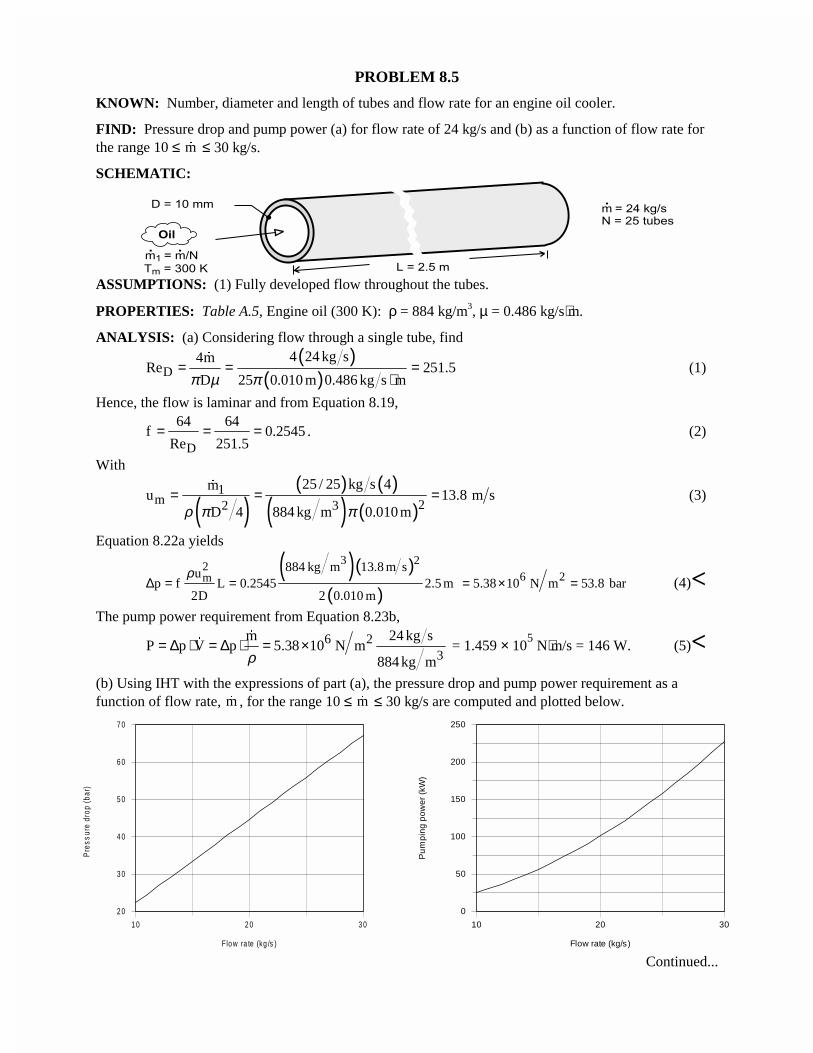
KNOWN: Number, diameter and length of tubes and flow rate for an engine oil cooler.
FIND: Pressure drop and pump power (a) for flow rate of 24 kg/s and (b) as a function of flow rate forthe range 10 ≤ �m ≤ 30 kg/s.
SCHEMATIC:
ASSUMPTIONS: (1) Fully developed flow throughout the tubes.
PROPERTIES: Table A.5, Engine oil (300 K): ρ = 884 kg/m3, µ = 0.486 kg/s⋅m.
ANALYSIS: (a) Considering flow through a single tube, find( )
( )D4 24 kg s4m
Re 251.5D 25 0.010 m 0.486 kg s mπ µ π
= = =⋅
�
(1)
Hence, the flow is laminar and from Equation 8.19,
D
64 64f 0.2545
Re 251.5= = = . (2)
With
( )( ) ( )
( ) ( )1
m 22 3
25 / 25 kg s 4mu 13.8 m s
D 4 884 kg m 0.010 mρ π π= = =
�
(3)
Equation 8.22a yields
( )( )( )
3 22m
884 kg m 13.8 m sup f L 0.2545 2.5 m
2D 2 0.010 m
ρ∆ = = 6 25.38 10 N m 53.8 bar= × = (4)<
The pump power requirement from Equation 8.23b,
6 23
m 24 kg sP p V p 5.38 10 N m
884 kg mρ= ∆ ⋅ = ∆ ⋅ = ×
�
� = 1.459 × 10⁵ N⋅m/s = 146 W. (5)<
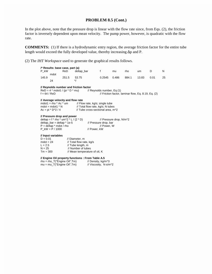
(b) Using IHT with the expressions of part (a), the pressure drop and pump power requirement as afunction of flow rate, �m , for the range 10 ≤ �m ≤ 30 kg/s are computed and plotted below.
Continued...
1 0 2 0 3 0
Flo w ra te (kg /s )
2 0
3 0
4 0
5 0
6 0
7 0
Pre
ssur
e dr
op (b
ar)
10 20 30
Flow rate (kg/s)
0
50
100
150
200
250
Pu
mp
ing
pow
er (k
W)
PROBLEM 8.5 (Cont.)
In the plot above, note that the pressure drop is linear with the flow rate since, from Eqs. (2), the frictionfactor is inversely dependent upon mean velocity. The pump power, however, is quadratic with the flowrate.
COMMENTS: (1) If there is a hydrodynamic entry region, the average friction factor for the entire tubelength would exceed the fully developed value, thereby increasing ∆p and P.
(2) The IHT Workspace used to generate the graphical results follows.
/* Results: base case, part (a)P_kW ReD deltap_bar f mu rho um D N
mdot145.9 251.5 53.75 0.2545 0.486 884.1 13.83 0.01 25
24 */
// Reynolds number and friction factorReD = 4 * mdot1 / (pi * D * mu) // Reynolds number, Eq (1)f = 64 / ReD // Friction factor, laminar flow, Eq. 8.19, Eq. (2)
// Average velocity and flow ratemdot1 = rho * Ac * um // Flow rate, kg/s; single tubemdot = mdot1 * N // Total flow rate, kg/s; N tubesAc = pi * D^2 / 4 // Tube cross-sectional area, m^2
// Pressure drop and powerdeltap = f * rho * um^2 * L / (2 * D) // Pressure drop, N/m^2deltap_bar = deltap * 1e-5 // Pressure drop, barP = deltap * mdot / rho // Power, WP_kW = P / 1000 // Power, kW
// Input variablesD = 0.01 // Diameter, mmdot = 24 // Total flow rate, kg/sL = 2.5 // Tube length, mN = 25 // Number of tubesTm = 300 // Mean temperature of oil, K
// Engine Oil property functions : From Table A.5rho = rho_T("Engine Oil",Tm) // Density, kg/m^3mu = mu_T("Engine Oil",Tm) // Viscosity, N·s/m^2
PROBLEM 8.6
KNOWN: The x-momentum equation for fully developed laminar flow in a parallel-plate channel2
2
dP d uconstant
dx dyµ= =
FIND: Following the same approach as for the circular tube in Section 8.1: (a) Show that the velocityprofile, u(y), is parabolic of the form
( )2
2
3( ) 1
2 / 2m
yu y u
a
= −
where um is the mean velocity expressed as
2
12m
a dPu
dxµ = −
and -dp/dx = ∆p/L where ∆p is the pressure drop across the channel of length L; (b) Write theexpression defining the friction factor, f, using the hydraulic diameter as the characteristic length, Dh;What is the hydraulic diameter for the parallel-plate channel? (c) The friction factor is estimated fromthe expression
hDf C Re= where C depends upon the flow cross-section as shown in Table 8.1;
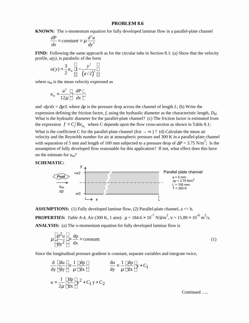
What is the coefficient C for the parallel-plate channel (b/a → ∞ ) ? (d) Calculate the mean airvelocity and the Reynolds number for air at atmospheric pressure and 300 K in a parallel-plate channelwith separation of 5 mm and length of 100 mm subjected to a pressure drop of ∆P = 3.75 N/m
2; Is the
assumption of fully developed flow reasonable for this application? If not, what effect does this haveon the estimate for um?
SCHEMATIC:
ASSUMPTIONS: (1) Fully developed laminar flow, (2) Parallel-plate channel, a << b.
PROPERTIES: Table A-4, Air (300 K, 1 atm): µ = 184.6 × 10⁻⁷
N⋅s/m2, ν = 15.89 × 10
-6 m
2/s.
ANALYSIS: (a) The x-momentum equation for fully developed laminar flow is
2
2d u dp
constantdxdy
µ = =
(1)
Since the longitudinal pressure gradient is constant, separate variables and integrate twice,
1d du 1 dp du 1 dp
y Cdy dy dx dy dxµ µ
= = +
21 2
1 dpu y C y C
2 dxµ = + +
Continued …..
PROBLEM 8.6 (Cont.)
The integration constants are determined from the boundary conditions,
( )y 0
du0 u a / 2 0
dy == =
to find
( )21 21 dp
C 0 C a / 22 dxµ
= = − giving
( ) ( )( )
2 2
2
a / 2 dp yu y 1
2 dx a / 2µ
= − − (2)
The mean velocity is
( ) ( )( )
a / 2
0
a / 22 3
m 20
a / 22 2 dp y / 3u u y dy y
a a 2 dx a / 2µ
= = − − ∫
2
ma dp
u12 dxµ
= − (3)
Substituting Eq. (3) for dp/dx into Eq. (2) find the velocity distribution in terms of the mean velocity
( )( )
2
m 23 y
u y u 12 a / 2
= −
< (4)
(b) The friction factor follows from its definition, Eq. 8.16,
( ) h2m
dp / dx Df
u / 2ρ
−=
⋅(5)
where the hydraulic diameter for the channel using Eq. 8.67 is
( )( )
ch
4 a b4 AD 2a
P 2 a b
×⋅= = =+
< (6)
since a << b.
(c) Substituting for the pressure gradient, Eq. (3), and rearranging, find using Eq. (6),
h
m h2 2 m h Dm
u D 96 96f
u D / Rea /12 u / 2 νµ ρ= = = < (7)
where the Reynolds number is
hD m hRe u D /ν= (8)
Continued …..
PROBLEM 8.6 (Cont.)
This result is in agreement with Table 8.1 for the cross-section with b/a → ∞ where
C = 96. <(d) For the conditions shown in the schematic, with air properties evaluated at 300 K, using Eqs. (3)and (8), find
( )2 2
m 7 2
0.005 m 3.75 N / mu 1.06 m / s
0.100 m12 184.6 10 N s / m−
= = × × ⋅
D 6 21.06 m / s 2 0.005 m
Re 66715.89 10 m / s−
× ×= =×
The flow is laminar as hDRe 2300,< and from Eq. 8.3, the entry length is
hfd,h
Dh am
x0.05 Re
D
=
"
fd,hx 2 0.005m 0.05 667 0.334 m 334 mm= × × × = =
We conclude that the flow is not fully developed, and the friction factor in the entry region will behigher than for fully developed conditions. Hence, for the same pressure drop, the mean velocity willbe less than our estimate.
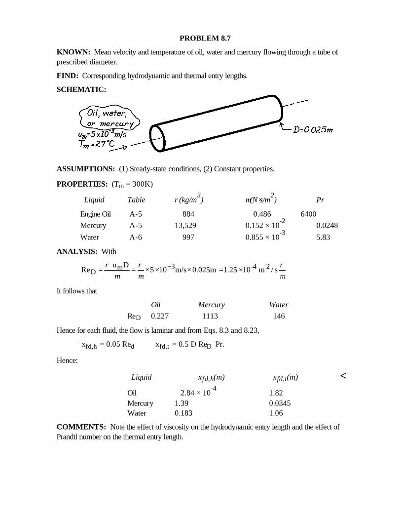
PROBLEM 8.7
KNOWN: Mean velocity and temperature of oil, water and mercury flowing through a tube ofprescribed diameter.
FIND: Corresponding hydrodynamic and thermal entry lengths.
SCHEMATIC:
ASSUMPTIONS: (1) Steady-state conditions, (2) Constant properties.
PROPERTIES: (Tm = 300K)
Liquid Table ρ(kg/m3) µ(N⋅s/m2
) Pr
Engine Oil A-5 884 0.486 6400Mercury A-5 13,529 0.152 × 10
-20.0248
Water A-6 997 0.855 × 10⁻³
5.83
ANALYSIS: With
3 -4 2mD
u DRe 5 10 m/s 0.025m 1.25 10 m / s
ρ ρ ρµ µ µ
−= = × × × = ×
It follows that
Oil Mercury WaterReD 0.227 1113 146
Hence for each fluid, the flow is laminar and from Eqs. 8.3 and 8.23,
fd,h d fd,t Dx 0.05 Re x 0.5 D Re Pr.= =
Hence:
Liquid xfd,h(m) xfd,t(m) <Oil 2.84 × 10
-41.82
Mercury 1.39 0.0345Water 0.183 1.06
COMMENTS: Note the effect of viscosity on the hydrodynamic entry length and the effect ofPrandtl number on the thermal entry length.
PROBLEM 8.8
KNOWN: Velocity and temperature profiles for laminar flow in a tube of radius ro = 10 mm.
FIND: Mean (or bulk) temperature, Tm, at this axial position.
SCHEMATIC:
ASSUMPTIONS: (1) Laminar incompressible flow, (2) Constant properties.
ANALYSIS: The prescribed velocity and temperature profiles, (m/s and K, respectively) are
u(r) = 0.1 [1-(r/ro)2] T(r) = 344.8 + 75.0 (r/ro)
2 - 18.8 (r/ro)4 (1,2)
For incompressible flow with constant cv in a circular tube, from Eq. 8.27, the mean temperature and um,the mean velocity, from Eq. 8.8 are, respectively,
( ) ( )orm 2 0
m o
2T u r T r r dr
u r= ⋅ ⋅ ⋅∫ ( )or
m 2 0o
2u u r r dr
r= ⋅ ⋅∫ (3,4)
Substituting the velocity profile, Eq. (1), into Eq. (4) and integrating, find
( ) ( ) ( )1 22m o o o o2 0
o
2u r 0.1 1 r r r r d r r
r= −
∫ ( ) ( )1
2 4o o
0
1 12 0.1 r r r r 0.05m / s
2 4= − =
Substituting the profiles and um into Eq. (3), find
( )( ){ } ( ) ( ){ } ( ) ( )1 2 2 42
m o o o o o o2 0o
2T r 0.1 1 r r 344.8 75.0 r r 18.8 r r r r d r r
0.05m s r= − + − ⋅ ⋅
∫
( ) ( ) ( ) ( ) ( ) ( ){ } ( )1 3 5 3 5 7m o o o o o o o0
T 4 344.8 r r 75.0 r r 18.8 r r 344.8 r r 75.0 r r 18.8 r r d r r= + − − + − ∫
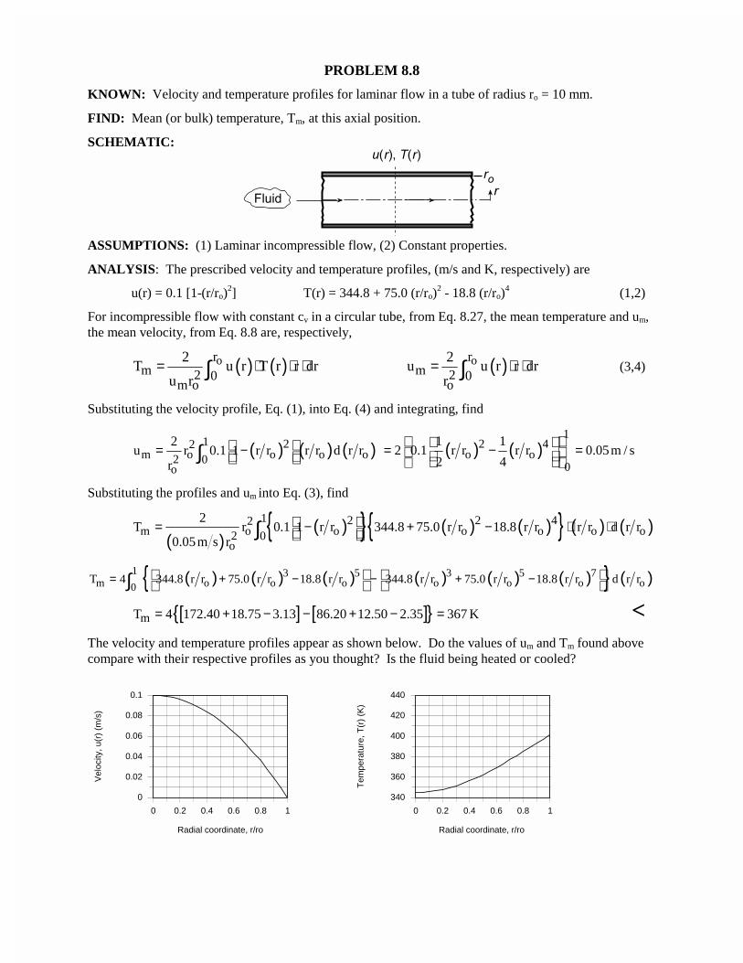
[ ] [ ]{ }mT 4 172.40 18.75 3.13 86.20 12.50 2.35 367 K= + − − + − = <The velocity and temperature profiles appear as shown below. Do the values of um and Tm found abovecompare with their respective profiles as you thought? Is the fluid being heated or cooled?
0 0.2 0.4 0.6 0.8 1
Radial coordinate, r/ro
0
0.02
0.04
0.06
0.08
0.1
Vel
ocity
, u(r
) (m
/s)
0 0.2 0.4 0.6 0.8 1
Radial coordinate, r/ro
340
360
380
400
420
440
Tem
pera
ture
, T(r
) (K
)
PROBLEM 8.9
KNOWN: Velocity and temperature profiles for laminar flow in a parallel plate channel.
FIND: Mean velocity, um, and mean (or bulk) temperature, Tm, at this axial position. Plot the velocityand temperature distributions. Comment on whether values of um and Tm appear reasonable.
SCHEMATIC:
ASSUMPTIONS: (1) Laminar incompressible flow, (2) Constant properties.
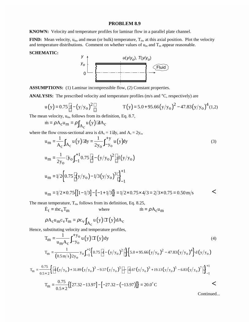
ANALYSIS: The prescribed velocity and temperature profiles (m/s and °C, respectively) are
( ) ( )2ou y 0.75 1 y y = − ( ) ( ) ( )2 4
o oT y 5.0 95.66 y y 47.83 y y= + − (1,2)
The mean velocity, um, follows from its definition, Eq. 8.7,
( )c
c m cAm A u u y dAρ ρ= = ⋅∫�
where the flow cross-sectional area is dAc = 1⋅dy, and Ac = 2yo,
( ) ( )c o
ym A yc o
1 1u u y dy u y dy
A 2y
+−
= ⋅ =∫ ∫ (3)
( ) ( )1 2m o o o1o
1u y 0.75 1 y y d y y
2y
+−
= ⋅ − ∫
( ) ( ){ } 13
m o o1
u 1 2 0.75 y y 1 3 y y+
− = −
[ ] [ ]{ }mu 1 2 0.75 1 1 3 1 1 3 1 2 0.75 4 3 2 3 0.75 0.50m s= × − − − + = × × = × = <The mean temperature, Tm, follows from its definition, Eq. 8.25,
t v mE mc T=� � where c mm A uρ=�
( ) ( )c
c m v m v cAA u c T c u y T y dAρ ρ= ⋅∫
Hence, substituting velocity and temperature profiles,
( ) ( )o
o
ym ym c
1T u y T y dy
u A
+−
= ⋅∫ (4)
( )( ){ } ( ) ( ){ } ( )1 2 2 4
m o o o o o1o
1T y 0.75 1 y y 5.0 95.66 y y 47.83 y y d y y
0.5 m s 2y
+−
= − + − ∫
( ) ( ) ( ) ( ) ( ) ( ){ } 13 5 3 5 7m o o o o o o
1
0.75T 5 y y 31.89 y y 9.57 y y 1.67 y y 19.13 y y 6.83 y y
0.5 2
+
−= + − − + −
×
[ ] ( )[ ]{ }m0.75
T 27.32 13.97 27.32 13.97 20.0 C0.5 2
= − − − − − =×
$ <Continued...
PROBLEM 8.9 (Cont.)
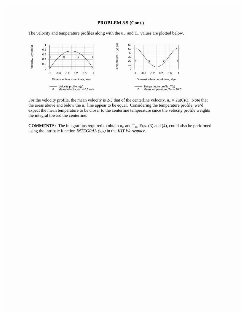
The velocity and temperature profiles along with the um and Tm values are plotted below.
-1 -0.6 -0.2 0.2 0.6 1
Dimensionless coordinate, x/xo
0
0.2
0.4
0.6
0.8
1
Vel
ocity
, u(y
) (m
/s)
Velocity profile, u(y)Mean velocity, um = 0.5 m/s
-1 -0.6 -0.2 0.2 0.6 1
Dimensionless coordinate, y/yo
0102030405060
Tem
pera
ture
, T(y
) (C
)
Temperature profile, T(y)Mean temperature, Tm = 20 C
For the velocity profile, the mean velocity is 2/3 that of the centerline velocity, um = 2u(0)/3. Note thatthe areas above and below the um line appear to be equal. Considering the temperature profile, we’dexpect the mean temperature to be closer to the centerline temperature since the velocity profile weightsthe integral toward the centerline.
COMMENTS: The integrations required to obtain um and Tm, Eqs. (3) and (4), could also be performedusing the intrinsic function INTEGRAL (y,x) in the IHT Workspace.
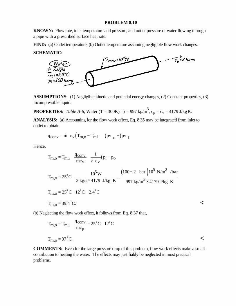
PROBLEM 8.10
KNOWN: Flow rate, inlet temperature and pressure, and outlet pressure of water flowing througha pipe with a prescribed surface heat rate.
FIND: (a) Outlet temperature, (b) Outlet temperature assuming negligible flow work changes.
SCHEMATIC:
ASSUMPTIONS: (1) Negligible kinetic and potential energy changes, (2) Constant properties, (3)Incompressible liquid.
PROPERTIES: Table A-6, Water (T = 300K): ρ = 997 kg/m3, cp = cv = 4179 J/kg⋅K.
ANALYSIS: (a) Accounting for the flow work effect, Eq. 8.35 may be integrated from inlet tooutlet to obtain
( ) ( ) ( )conv v m,o m,i o iq m c T T pv pv = − + − &
Hence,
( )convm,o m,i i o
v v
q 1T T p p
mc cρ= + + −
&
( ) ( )5 25m,o 3
100 2 bar 10 N/m /bar10 WT 25 C
2 kg/s 4179 J/kg K 997 kg/m 4179 J/kg K
−= + +
× ⋅ × ⋅o
m,oT 25 C 12 C 2.4 C= + +o o o
m,oT 39.4 C.= o <(b) Neglecting the flow work effect, it follows from Eq. 8.37 that,
convm,o m,i
p
qT T 25 C 12 C
mc= + = +o o
&
m,oT 37 C.= o <COMMENTS: Even for the large pressure drop of this problem, flow work effects make a smallcontribution to heating the water. The effects may justifiably be neglected in most practicalproblems.
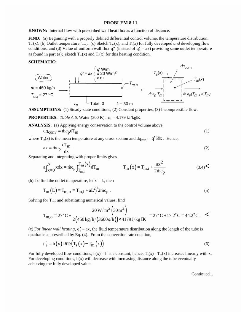
PROBLEM 8.11
KNOWN: Internal flow with prescribed wall heat flux as a function of distance.
FIND: (a) Beginning with a properly defined differential control volume, the temperature distribution,Tm(x), (b) Outlet temperature, Tm,o, (c) Sketch Tm(x), and Ts(x) for fully developed and developing flowconditions, and (d) Value of uniform wall flux ��qs (instead of �qs = ax) providing same outlet temperatureas found in part (a); sketch Tm(x) and Ts(x) for this heating condition.
SCHEMATIC:
ASSUMPTIONS: (1) Steady-state conditions, (2) Constant properties, (3) Incompressible flow.
PROPERTIES: Table A.6, Water (300 K): cp = 4.179 kJ/kg⋅K.
ANALYSIS: (a) Applying energy conservation to the control volume above,
conv p mdq mc dT= � (1)
where Tm(x) is the mean temperature at any cross-section and dqconv = q dx′ ⋅ . Hence,
mp
dTax mc
dx= � . (2)
Separating and integrating with proper limits gives
( )m
m,i
x T xp mx 0 T
a xdx mc dT=
=∫ ∫� ( )2
m m,ip
axT x T
2mc= +
�(3,4)<
(b) To find the outlet temperature, let x = L, then
( ) 2m m,o m,i pT L T T aL 2mc= = + � . (5)
Solving for Tm,o and substituting numerical values, find
( )( )( )
2 2
m,o
20 W m 30mT 27 C
2 450 kg h 3600s h 4179J kg K= +
× ⋅$ 27 C 17.2 C 44.2 C= + =$ $ $ . <
(c) For linear wall heating, � q axs , the fluid temperature distribution along the length of the tube isquadratic as prescribed by Eq. (4). From the convection rate equation,
( ) ( ) ( )( )s s mq h x D T x T xπ′ = ⋅ − (6)
For fully developed flow conditions, h(x) = h is a constant; hence, Ts(x) - Tm(x) increases linearly with x.For developing conditions, h(x) will decrease with increasing distance along the tube eventuallyachieving the fully developed value.
Continued...
PROBLEM 8.11 (Cont.)
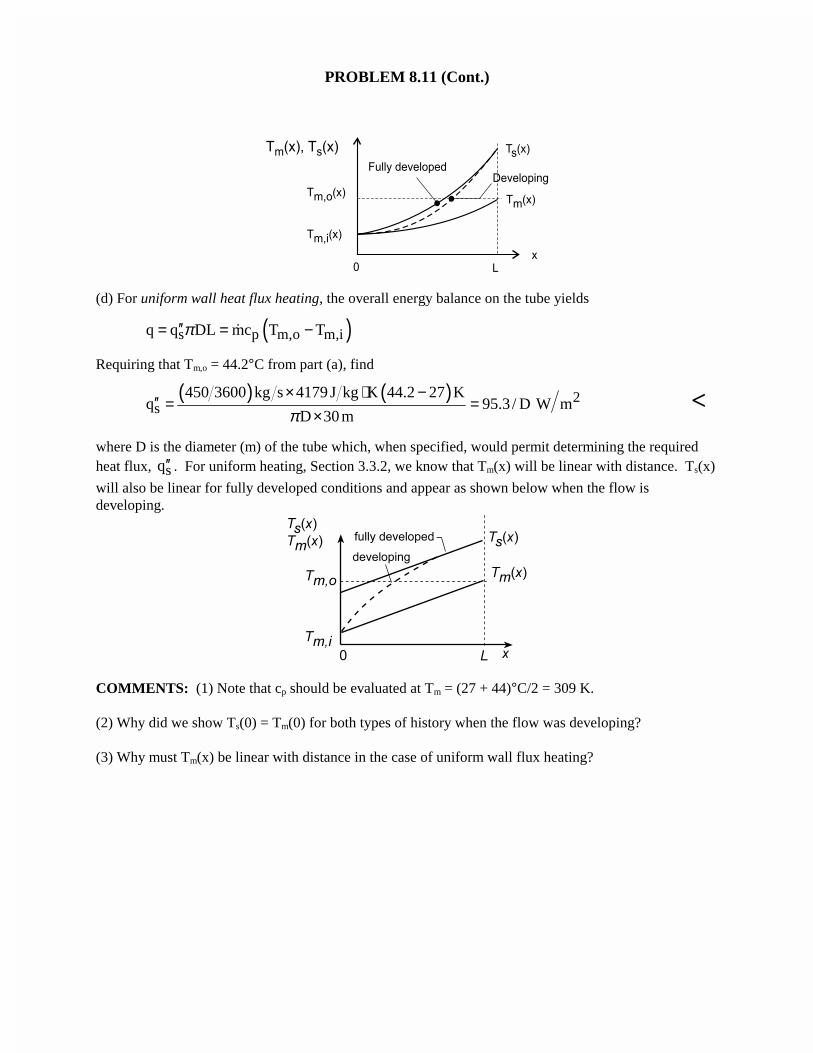
(d) For uniform wall heat flux heating, the overall energy balance on the tube yields
( )s p m,o m,iq q DL mc T Tπ′′= = −�
Requiring that Tm,o = 44.2°C from part (a), find
( ) ( ) 2s
450 3600 kg s 4179 J kg K 44.2 27 Kq 95.3 / D W m
D 30 mπ× ⋅ −
′′ = =×
<
where D is the diameter (m) of the tube which, when specified, would permit determining the requiredheat flux, sq′′ . For uniform heating, Section 3.3.2, we know that Tm(x) will be linear with distance. Ts(x)
will also be linear for fully developed conditions and appear as shown below when the flow isdeveloping.
COMMENTS: (1) Note that cp should be evaluated at Tm = (27 + 44)°C/2 = 309 K.
(2) Why did we show Ts(0) = Tm(0) for both types of history when the flow was developing?
(3) Why must Tm(x) be linear with distance in the case of uniform wall flux heating?
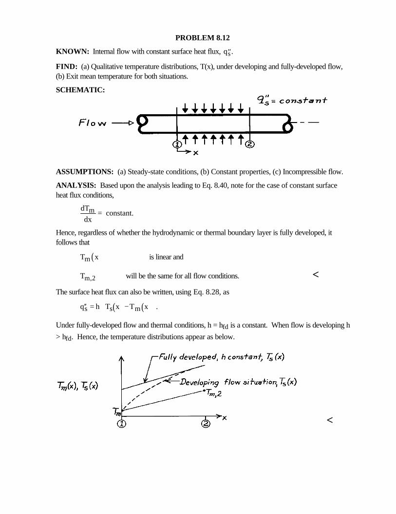
PROBLEM 8.12
KNOWN: Internal flow with constant surface heat flux, ′′qs .
FIND: (a) Qualitative temperature distributions, T(x), under developing and fully-developed flow,(b) Exit mean temperature for both situations.
SCHEMATIC:
ASSUMPTIONS: (a) Steady-state conditions, (b) Constant properties, (c) Incompressible flow.
ANALYSIS: Based upon the analysis leading to Eq. 8.40, note for the case of constant surfaceheat flux conditions,
mdT constant.
dx=
Hence, regardless of whether the hydrodynamic or thermal boundary layer is fully developed, itfollows that
( )mT x is linear and
m,2T will be the same for all flow conditions. <The surface heat flux can also be written, using Eq. 8.28, as
( ) ( )s s mq h T x T x .′′ = −
Under fully-developed flow and thermal conditions, h = hfd is a constant. When flow is developing h
> hfd. Hence, the temperature distributions appear as below.
<
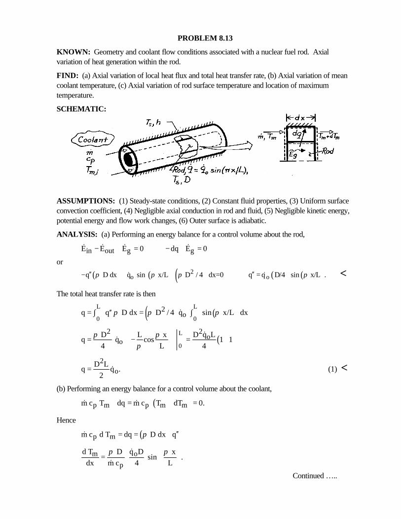
PROBLEM 8.13
KNOWN: Geometry and coolant flow conditions associated with a nuclear fuel rod. Axialvariation of heat generation within the rod.
FIND: (a) Axial variation of local heat flux and total heat transfer rate, (b) Axial variation of meancoolant temperature, (c) Axial variation of rod surface temperature and location of maximumtemperature.
SCHEMATIC:
ASSUMPTIONS: (1) Steady-state conditions, (2) Constant fluid properties, (3) Uniform surfaceconvection coefficient, (4) Negligible axial conduction in rod and fluid, (5) Negligible kinetic energy,potential energy and flow work changes, (6) Outer surface is adiabatic.
ANALYSIS: (a) Performing an energy balance for a control volume about the rod,
in out g gE E E 0 dq E 0− + = − + =& & & &
or
( ) ( ) ( ) ( ) ( )2o oq D dx q sin x/L D / 4 dx=0 q q D/4 sin x/L .π π π π′′ ′′− + =& & <
The total heat transfer rate is then
( ) ( )L L
0 02
oq q D dx D / 4 q sin x/L dxπ π π′′= ∫ = ∫&
( )L
0
22o
oD q L D L x
q q cos 1 14 L 4
π ππ
= − = + &
&
2o
D Lq q .
2= & (1) <
(b) Performing an energy balance for a control volume about the coolant,
( )p m p m mm c T dq m c T dT 0.+ = + =& &
Hence
( )p mm c d T dq D dx qπ ′′= =&
om
p
q Dd T D x sin .
dx m c 4 Lπ π =
&
&
Continued …..
PROBLEM 8.13 (Cont.)
Integrating,
( )x
0
2o
m m,ip
q D xT x T sin dx
4 m c Lπ π− = ∫
&
&
( )2
om m,i
p
qL D xT x T 1 cos
4 m c Lπ = + −
&
&
(2) <(c) From Newton’s law of cooling,
( )s mq h T T .′′ = −
Hence
s mq
T Th
′′= +
2o o
s m,ip
q D q x LD xT sin T 1 cos .
4h L 4 m c Lπ π = + + −
& &
&<
To determine the location of the maximum surface temperature, evaluate
2s o o
p
d T q D q x LD x0 cos sin
dx 4hL L 4 m c L Lπ π π π= = +
& &
&
or
p
1 x D x cos sin 0.
hL L m c Lπ π+ =
&
Hence
pm c xtan
L D h Lπ = −
&
p1max
m cLx tan x .
D h Lπ−
= − =
& <
COMMENTS: Note from Eq. (2) that
( )2
om,o m m,i
p
L D qT T L T
2 m c= = +
&
&
which is equivalent to the result obtained by combining Eq. (1) and Eq. 8.37.
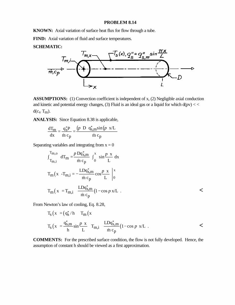
PROBLEM 8.14
KNOWN: Axial variation of surface heat flux for flow through a tube.
FIND: Axial variation of fluid and surface temperatures.
SCHEMATIC:
ASSUMPTIONS: (1) Convection coefficient is independent of x, (2) Negligible axial conductionand kinetic and potential energy changes, (3) Fluid is an ideal gas or a liquid for which d(pv) < <d(cv Tm).
ANALYSIS: Since Equation 8.38 is applicable,
( ) ( )s,msm
p p
D q sin x/Lq PdTdx m c m c
π π′′′′= =
& &
Separating variables and integrating from x = 0
T xm,o
T 0m,i
s,mm
p
Dq x dT sin dx
m c L
π π′′∫ = ∫
&
( )x
0
s,mm m,i
p
LDq xT x -T cos
m c Lπ′′
= −&
( ) ( )s,mm m,i
p
LDqT x T 1 cos x/L .
m cπ
′′= + −
&<
From Newton’s law of cooling, Eq. 8.28,
( ) ( ) ( )s s mT x q / h T x′′= +
( ) ( )s,m s,ms m,i
p
q LDq xT x sin T 1 cos x/L .
h L m cπ π
′′ ′′= + + −
&<
COMMENTS: For the prescribed surface condition, the flow is not fully developed. Hence, theassumption of constant h should be viewed as a first approximation.
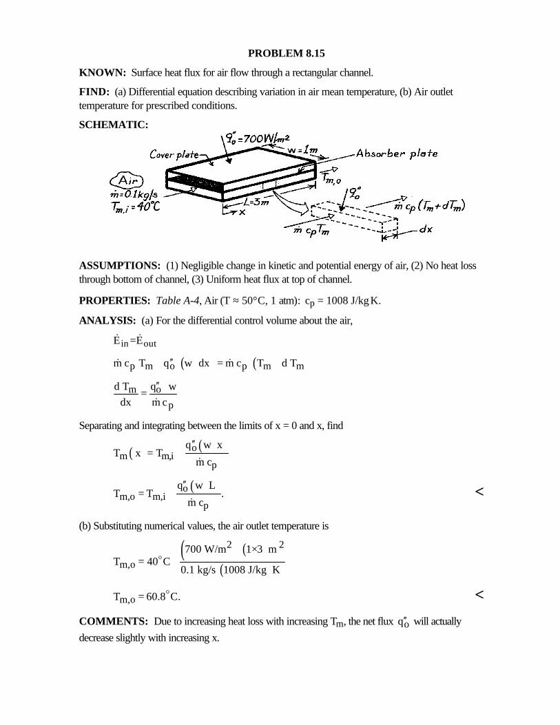
PROBLEM 8.15
KNOWN: Surface heat flux for air flow through a rectangular channel.
FIND: (a) Differential equation describing variation in air mean temperature, (b) Air outlettemperature for prescribed conditions.
SCHEMATIC:
ASSUMPTIONS: (1) Negligible change in kinetic and potential energy of air, (2) No heat lossthrough bottom of channel, (3) Uniform heat flux at top of channel.
PROPERTIES: Table A-4, Air (T ≈ 50°C, 1 atm): cp = 1008 J/kg⋅K.
ANALYSIS: (a) For the differential control volume about the air,
in outE =E& &
( ) ( )p m o p m mm c T q w dx m c T d T′′+ ⋅ = +& &
om
p
q wd Tdx m c
′′ ⋅=&
Separating and integrating between the limits of x = 0 and x, find
( ) ( )om m,i
p
q w xT x T
m c
′′ ⋅= +
&
( )om,o m,i
p
q w LT T .
m c
′′ ⋅= +
&<
(b) Substituting numerical values, the air outlet temperature is
( ) ( )( )
2 2
m,o700 W/m 1 3 m
T 40 C0.1 kg/s 1008 J/kg K
×= +
⋅o
m,oT 60.8 C.= o <
COMMENTS: Due to increasing heat loss with increasing Tm, the net flux oq′′ will actually
decrease slightly with increasing x.
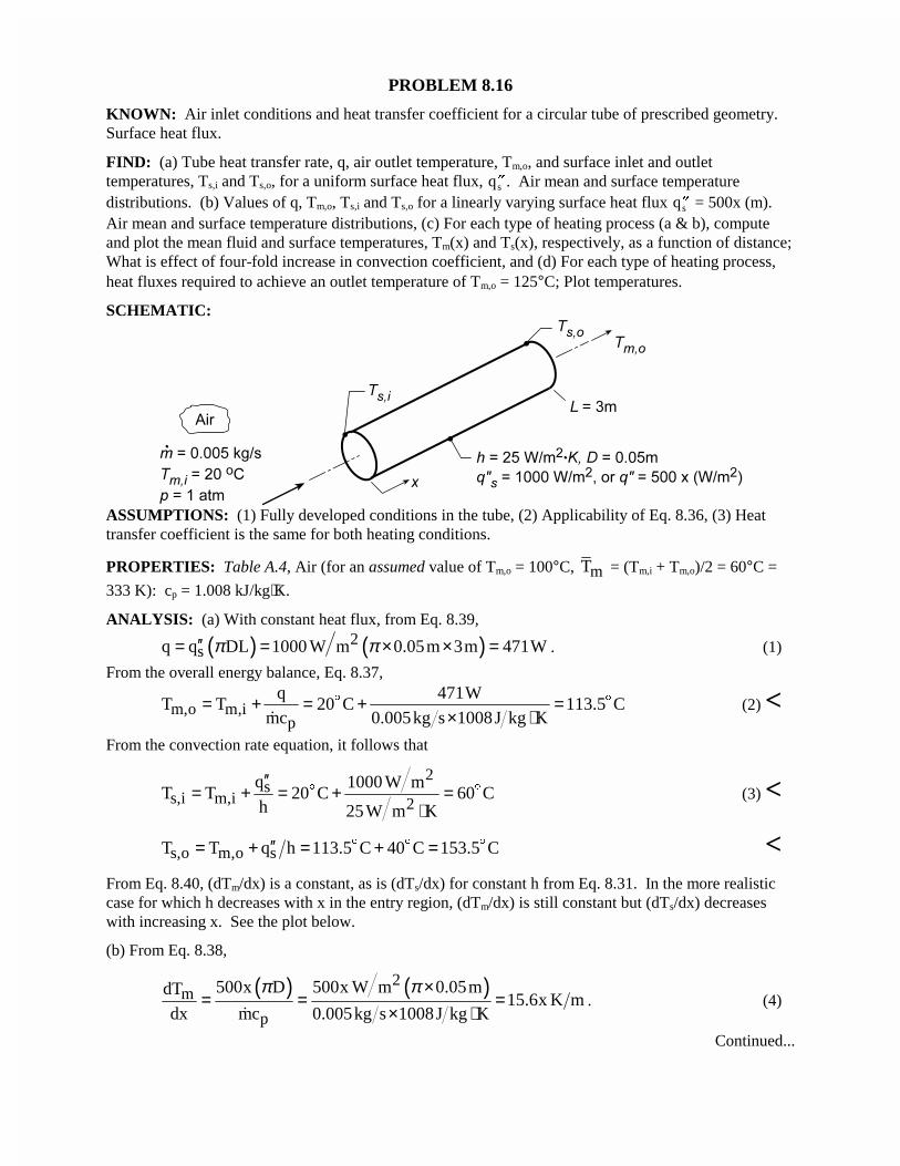
PROBLEM 8.16
KNOWN: Air inlet conditions and heat transfer coefficient for a circular tube of prescribed geometry.Surface heat flux.
FIND: (a) Tube heat transfer rate, q, air outlet temperature, Tm,o, and surface inlet and outlettemperatures, Ts,i and Ts,o, for a uniform surface heat flux, ��qs . Air mean and surface temperaturedistributions. (b) Values of q, Tm,o, Ts,i and Ts,o for a linearly varying surface heat flux ��qs = 500x (m).Air mean and surface temperature distributions, (c) For each type of heating process (a & b), computeand plot the mean fluid and surface temperatures, Tm(x) and Ts(x), respectively, as a function of distance;What is effect of four-fold increase in convection coefficient, and (d) For each type of heating process,heat fluxes required to achieve an outlet temperature of Tm,o = 125°C; Plot temperatures.
SCHEMATIC:
ASSUMPTIONS: (1) Fully developed conditions in the tube, (2) Applicability of Eq. 8.36, (3) Heattransfer coefficient is the same for both heating conditions.
PROPERTIES: Table A.4, Air (for an assumed value of Tm,o = 100°C, mT = (Tm,i + Tm,o)/2 = 60°C =
333 K): cp = 1.008 kJ/kg⋅K.
ANALYSIS: (a) With constant heat flux, from Eq. 8.39,
( ) ( )2sq q DL 1000 W m 0.05m 3m 471Wπ π′′= = × × = . (1)
From the overall energy balance, Eq. 8.37,
m,o m,ip
q 471WT T 20 C 113.5 C
mc 0.005kg s 1008J kg K= + = + =
× ⋅$ $
�(2) <
From the convection rate equation, it follows that
2s
s,i m,i 2q 1000 W m
T T 20 C 60 Ch 25W m K
′′= + = + =
⋅$ $ (3) <
s,o m,o sT T q h 113.5 C 40 C 153.5 C′′= + = + =$ $ $ <From Eq. 8.40, (dTm/dx) is a constant, as is (dTs/dx) for constant h from Eq. 8.31. In the more realisticcase for which h decreases with x in the entry region, (dTm/dx) is still constant but (dTs/dx) decreaseswith increasing x. See the plot below.
(b) From Eq. 8.38,
( ) ( )2m
p
500x D 500x W m 0.05mdT15.6x K m
dx mc 0.005kg s 1008J kg K
π π×= = =
× ⋅�. (4)
Continued...
PROBLEM 8.16 (Cont.)
Integrating from x = 0 to L it follows that323
m,o m,i 00
xT T 15.6 xdx 20 C 15.6 20 C 70.2 C
2= + = + = +∫ $ $ $ = 90.2°C. (5) <
The heat rate is
( )323
s s 00
xq q dA 500 0.05m xdx 78.5 353W
2π′′= = × = =∫ ∫ <
From Eq. 8.28 it then follows that2
2s m s m,i
x 500T T q h T 15.6 x 20 C 7.8x 20x
2 25′′= + = + + = + +$ (6)
Hence, at the inlet (x = 0) and outlet (x = L),
s,i m,iT T 20 C= = $ and s,oT 150.2 C= $ <Note that (dTs/dx) and (dTm/dx) both increase linearly with x, but (dTs/dx) > (dTm/dx).
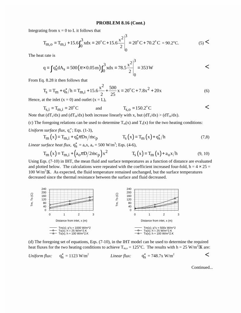
(c) The foregoing relations can be used to determine Tm(x) and Ts(x) for the two heating conditions:
Uniform surface flux, ��qs ; Eqs. (1-3),
( )m m,i s pT x T q Dx mcπ′′= + � ( ) ( )s m sT x T x q h′′= + (7,8)
Linear surface heat flux, sq′′ = aox, ao = 500 W/m3; Eqs. (4-6),
( ) ( ) 2m m,i o pT x T a D 2mc xπ= + � ( ) ( )s m oT x T x a x h= + (9, 10)
Using Eqs. (7-10) in IHT, the mean fluid and surface temperatures as a function of distance are evaluatedand plotted below. The calculations were repeated with the coefficient increased four-fold, h = 4 × 25 =100 W/m2⋅K. As expected, the fluid temperature remained unchanged, but the surface temperaturesdecreased since the thermal resistance between the surface and fluid decreased.
0 1 2 3
Distance from inlet, x (m)
04080
120160200240
Tm
, Ts
(C)
Tm(x); q''s = 1000 W/m^2Ts(x); h = 25 W/m^2.KTs(x); h = 100 W/m^2.K
0 1 2 3
Distance from inlet, x (m)
04080
120160200240
Tm
, Ts
(C)
Tm(x); q''s = 500x W/m^2Ts(x); h = 25 W/m^2.KTs(x); h = 100 W/m^2.K
(d) The foregoing set of equations, Eqs. (7-10), in the IHT model can be used to determine the requiredheat fluxes for the two heating conditions to achieve Tm,o = 125°C. The results with h = 25 W/m2⋅K are:
Uniform flux: sq′′ = 1123 W/m2 Linear flux: sq′′ = 748.7x W/m2 <
Continued...
PROBLEM 8.16 (Cont.)
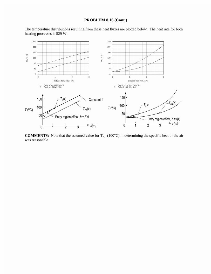
The temperature distributions resulting from these heat fluxes are plotted below. The heat rate for bothheating processes is 529 W.
0 1 2 3
Distance from inlet, x (m)
0
40
80
120
160
200
240
Tm
, Ts
(C)
Tm(x); q''s = 1123 W/m^2Ts(x); h = 25 W/m^2.K
0 1 2 3
Distance from inlet, x (m)
0
40
80
120
160
200
240
Tm
, Ts
(C)
Tm(x); q''s = 749x (W/m^2) Ts(x); h = 25 W/m^2.K
COMMENTS: Note that the assumed value for Tm,o (100°C) in determining the specific heat of the airwas reasonable.
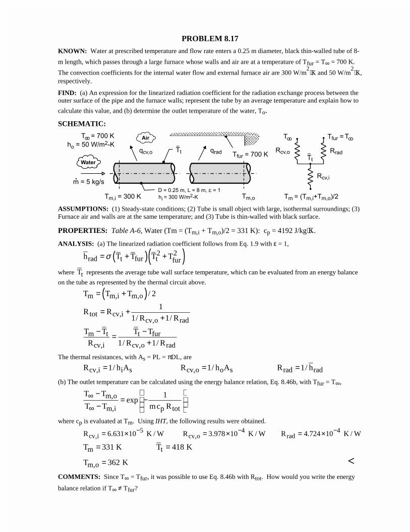
PROBLEM 8.17
KNOWN: Water at prescribed temperature and flow rate enters a 0.25 m diameter, black thin-walled tube of 8-
m length, which passes through a large furnace whose walls and air are at a temperature of Tfur = T∞ = 700 K.
The convection coefficients for the internal water flow and external furnace air are 300 W/m2⋅K and 50 W/m
2⋅K,
respectively.
FIND: (a) An expression for the linearized radiation coefficient for the radiation exchange process between theouter surface of the pipe and the furnace walls; represent the tube by an average temperature and explain how to
calculate this value, and (b) determine the outlet temperature of the water, To.
SCHEMATIC:
ASSUMPTIONS: (1) Steady-state conditions; (2) Tube is small object with large, isothermal surroundings; (3)Furnace air and walls are at the same temperature; and (3) Tube is thin-walled with black surface.
PROPERTIES: Table A-6, Water (Tm = (Tm,i + Tm,o)/2 = 331 K): cp = 4192 J/kg⋅K.
ANALYSIS: (a) The linearized radiation coefficient follows from Eq. 1.9 with ε = 1,
( )( )2 2rad t fur t furh T T T Tσ= + +
where tT represents the average tube wall surface temperature, which can be evaluated from an energy balance
on the tube as represented by the thermal circuit above.
( )m m,i m,oT T T / 2= +
tot cv,icv,o rad
1R R
1/ R 1/ R= +
+
m t t fur
cv,i cv,o rad
T T T T
R 1/ R 1/ R
− −=+
The thermal resistances, with As = PL = πDL, are
cv,i i s cv,o o s rad radR 1/ h A R 1/ h A R 1/ h= = =
(b) The outlet temperature can be calculated using the energy balance relation, Eq. 8.46b, with Tfur = T∞,
m,o
m,i p tot
T T 1exp
T T mc R∞
∞
−= − −
where cp is evaluated at Tm. Using IHT, the following results were obtained.
5 4 4cv,i cv,o radR 6.631 10 K / W R 3.978 10 K / W R 4.724 10 K / W− − −= × = × = ×
m tT 331 K T 418 K= =
m,oT 362 K= <COMMENTS: Since T∞ = Tfur, it was possible to use Eq. 8.46b with Rtot. How would you write the energy
balance relation if T∞ ≠ Tfur?
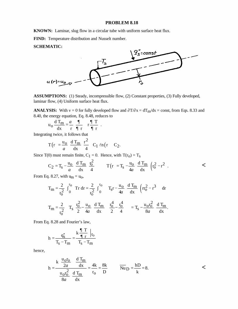
PROBLEM 8.18
KNOWN: Laminar, slug flow in a circular tube with uniform surface heat flux.
FIND: Temperature distribution and Nusselt number.
SCHEMATIC:
ASSUMPTIONS: (1) Steady, incompressible flow, (2) Constant properties, (3) Fully developed,laminar flow, (4) Uniform surface heat flux.
ANALYSIS: With v = 0 for fully developed flow and ∂T/∂x = dTm/dx = const, from Eqs. 8.33 and8.40, the energy equation, Eq. 8.48, reduces to
mo
d T Tu r .
dx r r rα ∂ ∂
∂ ∂ =
Integrating twice, it follows that
( ) ( )2
o m1 2
u d T rT r C n r C .
dx 4α= + +l
Since T(0) must remain finite, C1 = 0. Hence, with T(ro) = Ts
( ) ( )22 2o o om m
2 s s ou r ud T d T
C T T r T r r .dx 4 4 dxα α
= − = − − <From Eq. 8.27, with um = uo,
( )r ro o
0 02 3o m
m s o2 2o o
u2 2 d TT Tr dr T r rr r dr
4 dxr r α = ∫ = ∫ − −
2 4 4 2o o o o o om m
m s s2o
r u r r u r2 d T d TT T T .
2 4 dx 2 4 8 dxr α α
= − − = −
From Eq. 8.28 and Fourier’s law,
ors
s m s m
Tk q rh
T T T T
∂∂′′
= =− −
hence,
o o m
D2 oo o m
u r d Tk
4k 8k hD2 dxh Nu 8.r D ku r d T
8 dx
α
α
= = = = = <
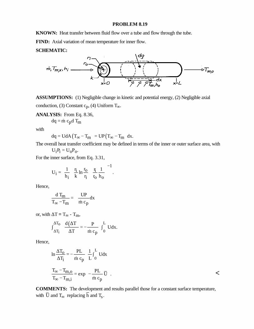
PROBLEM 8.19
KNOWN: Heat transfer between fluid flow over a tube and flow through the tube.
FIND: Axial variation of mean temperature for inner flow.
SCHEMATIC:
ASSUMPTIONS: (1) Negligible change in kinetic and potential energy, (2) Negligible axial
conduction, (3) Constant cp, (4) Uniform T∞.
ANALYSIS: From Eq. 8.36,
p mdq m c d T= &
with( ) ( )m mdq UdA T T UP T T dx.∞ ∞= − = −
The overall heat transfer coefficient may be defined in terms of the inner or outer surface area, with
i i o oU P U P .=For the inner surface, from Eq. 3.31,
1oi i
ii i o o
r1 r r 1U ln .
h k r r h
− = + +
Hence,
m
m p
d T UPdx
T T m c∞= +
− &
or, with ∆T ≡ T∞ - Tm,
( )T Lo
T 0i p
d T P Udx.
T m c
∆
∆
∆∫ = − ∫
∆ &
Hence,
L
0o
i p
T PL 1ln Udx
T m c L ∆ = − ∫ ∆ &
m,o
m,i p
T T PLexp U .
T T m c∞
∞
−= − − &
<
COMMENTS: The development and results parallel those for a constant surface temperature,with sU and T replacing h and T .∞
PROBLEM 8.20
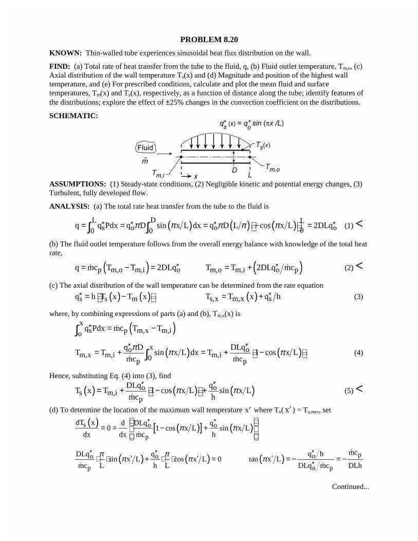
KNOWN: Thin-walled tube experiences sinusoidal heat flux distribution on the wall.
FIND: (a) Total rate of heat transfer from the tube to the fluid, q, (b) Fluid outlet temperature, Tm,o, (c)Axial distribution of the wall temperature Ts(x) and (d) Magnitude and position of the highest walltemperature, and (e) For prescribed conditions, calculate and plot the mean fluid and surfacetemperatures, Tm(x) and Ts(x), respectively, as a function of distance along the tube; identify features ofthe distributions; explore the effect of ±25% changes in the convection coefficient on the distributions.
SCHEMATIC:
ASSUMPTIONS: (1) Steady-state conditions, (2) Negligible kinetic and potential energy changes, (3)Turbulent, fully developed flow.
ANALYSIS: (a) The total rate heat transfer from the tube to the fluid is
( ) ( ) ( )L D Ls o o o00 0
q q Pdx q D sin x L dx q D L cos x L 2DLqπ π π π π′′ ′′ ′′ ′′ = = = − = ∫ ∫ (1) <(b) The fluid outlet temperature follows from the overall energy balance with knowledge of the total heatrate,
( )p m,o m,i oq mc T T 2DLq′′= − =� ( )m,o m,i o pT T 2DLq mc′′= + � (2) <(c) The axial distribution of the wall temperature can be determined from the rate equation
( ) ( )s s mq h T x T x′′ = − ( )s,x m,x sT T x q h′′= + (3)
where, by combining expressions of parts (a) and (b), Tm,x(x) is
( )xs p m,x m,io
q Pdx mc T T′′ = −∫ �
( ) ( )xo om,x m,i m,i0p p
q D DLqT T sin x L dx T 1 cos x L
mc mc
π π π′′ ′′
= + = + − ∫� �
(4)
Hence, substituting Eq. (4) into (3), find
( ) ( ) ( )o os m,i
p
DLq qT x T 1 cos x L sin x L
mc hπ π
′′ ′′ = + − +
�(5) <
(d) To determine the location of the maximum wall temperature �x where Tx( x′ ) = Ts,max, set
( ) ( )[ ] ( )s o o
p
dT x DLq qd0 1 cos x L sin x L
dx dx mc hπ π
′′ ′′= = − +
�
( ) ( )o o
p
DLq qsin x L cos x L 0
mc L h L
π ππ π
′′ ′′′ ′⋅ ⋅ + ⋅ ⋅ =
�
( ) po
o p
mcq htan x L
DLq mc DLhπ
′′′ = − = −
′′
�
�
Continued...
PROBLEM 8.20 (Cont.)
( )1p
Lx tan mc DLh
π−′ = − � (6) <
At this location, the wall temperature is
( ) ( ) ( )o os,max s m,i
p
DLq qT T x T 1 cos x L sin x L
mc hπ π
′′ ′′′ ′ ′ = = + − + �
(7) <
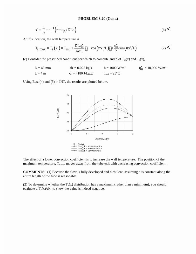
(e) Consider the prescribed conditions for which to compute and plot Tm(x) and Ts(x),
D = 40 mm m� = 0.025 kg/s h = 1000 W/m2oq′′ = 10,000 W/m2
L = 4 m cp = 4180 J/kg⋅K Tm,i = 25°C
Using Eqs. (4) and (5) in IHT, the results are plotted below.
0 1 2 3 4
Distance, x (m)
25
30
35
40
45
Ts,
Tm
(C
)
Tm(x) Ts(x); h = 1250 W/m^2.KTs(x); h = 1000 W/m^2.KTs(x); h = 750 W/m^2.K
The effect of a lower convection coefficient is to increase the wall temperature. The position of themaximum temperature, Ts,max, moves away from the tube exit with decreasing convection coefficient.
COMMENTS: (1) Because the flow is fully developed and turbulent, assuming h is constant along theentire length of the tube is reasonable.
(2) To determine whether the Tx(x) distribution has a maximum (rather than a minimum), you shouldevaluate d2Ts(x)/dx2 to show the value is indeed negative.
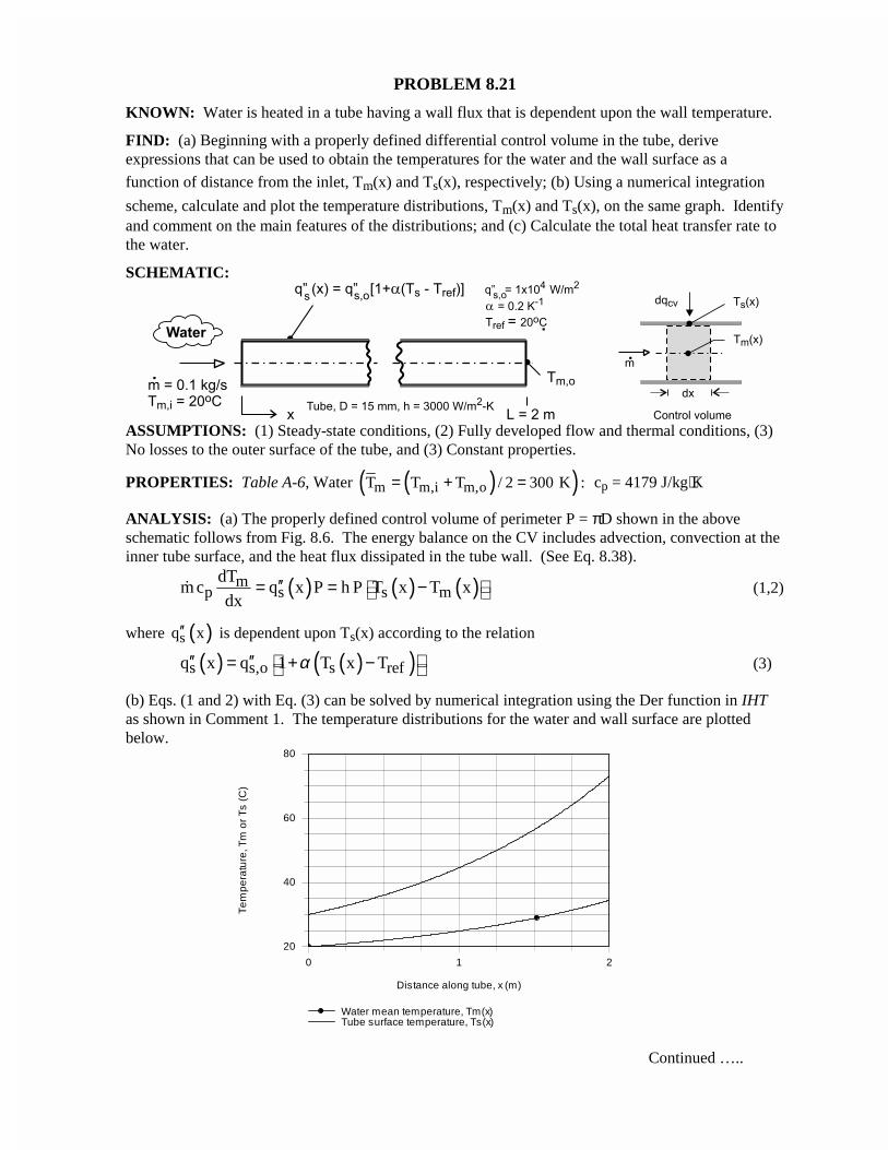
PROBLEM 8.21
KNOWN: Water is heated in a tube having a wall flux that is dependent upon the wall temperature.
FIND: (a) Beginning with a properly defined differential control volume in the tube, deriveexpressions that can be used to obtain the temperatures for the water and the wall surface as a
function of distance from the inlet, Tm(x) and Ts(x), respectively; (b) Using a numerical integration
scheme, calculate and plot the temperature distributions, Tm(x) and Ts(x), on the same graph. Identifyand comment on the main features of the distributions; and (c) Calculate the total heat transfer rate tothe water.
SCHEMATIC:
ASSUMPTIONS: (1) Steady-state conditions, (2) Fully developed flow and thermal conditions, (3)No losses to the outer surface of the tube, and (3) Constant properties.
PROPERTIES: Table A-6, Water ( )( )m m,i m,oT T T / 2 300 K := + = cp = 4179 J/kg⋅K
ANALYSIS: (a) The properly defined control volume of perimeter P = πD shown in the aboveschematic follows from Fig. 8.6. The energy balance on the CV includes advection, convection at theinner tube surface, and the heat flux dissipated in the tube wall. (See Eq. 8.38).
( ) ( ) ( )mp s s m
dTm c q x P h P T x T x
dx′′ = = − � (1,2)
where ( )sq x′′ is dependent upon Ts(x) according to the relation
( ) ( )( )s s,o s refq x q 1 T x Tα ′′ ′′= + − (3)
(b) Eqs. (1 and 2) with Eq. (3) can be solved by numerical integration using the Der function in IHTas shown in Comment 1. The temperature distributions for the water and wall surface are plottedbelow.
Continued …..
0 1 2
Distance along tube, x (m)
20
40
60
80
Te
mp
era
ture
, Tm
or
Ts
(C
)
Water mean temperature, Tm(x)Tube surface temperature, Ts(x)
PROBLEM 8.21 (Cont.)(c) The total heat transfer to the water can be evaluated from an overall energy balance on the water,
( )p m,o m,iq m c T T= −� (4)
( )q 0.1 kg / s 4179 J / kg K 34.4 20 K 6018 W= × ⋅ − = <Alternatively, the heat rate can be evaluated by integration of the heat flux from the tube surface overthe length of the tube,
( )L
0sq q x Pdx′′= ∫ (5)
where ( )sq x′′ is given by Eq. (3), and Ts(x) and Tm(x) are determined from the differential form of
the energy equation, Eqs. (1) and (2). The result as shown in the IHT code below is 6005 W.
COMMENTS: (1) Note that Tm(x) increases with distance greater than linearly, as expected since sq (x)′′ does.
Also as expected, the difference, Ts(x) – Tm(x), likewise increases with distance greater than linearly.
(2) In the foregoing analysis, cp is evaluated at the mean fluid temperature Tm = (Tm,i + Tm,o)/2.(3) The IHT code representing the foregoing equations to calculate and plot the temperaturedistribution and to calculate the total heat rate to the water is shown below.
/* Results: integration for distributions; conditions at x = 2 mF_xTs Ts q' q''s_x x Tm11.64 73.18 5483 1.164E5 2 34.393 30 1414 3E4 0 20 */
/* Results: heat rate by energy balances on fluid and tube surfaceq_eb q_hf6018 6005 */
/* Results: for evaluating cp at TmTs cp q''s_x x Tm73.31 4179 1.166E5 2 34.4430 4179 3E4 0 20 */
// Energy balancesmdot * cp * der(Tm,x) = q' // Energy balance, Eq. 8.38q' = q''s_x * Pq''s_x = q''o * F_xTsq' = h * P * (Ts - Tm) // Convection rate equationP = pi * D
// Surface heat flux specificationF_xTs = (1 + alpha * (Ts -Tref))alpha = 0.2Tref = 20
// Overall heat rate// Energy balance on the fluidq_eb = mdot * cp * (Tmo - Tmi)Tmi = 20Tmo = 34.4 // From initial solve// Integration of the surface heat fluxq_hf = q''o * P * INTEGRAL(F_xTs, x)
// Input variablesmdot = 0.1D = 0.015h = 3000q''o = 1.0e4// L = 2 // Limit of integration over x// Tmi = 20 // Initial condition for integration
// Water property functions :T dependence, From Table A.6// Units: T(K), p(bars);xx = 0 // Quality (0=sat liquid or 1=sat vapor)cp = cp_Tx("Water",Tmm,xx) // Specific heat, J/kg·KTmm = (20 + 34.4) / 2 + 273
PROBLEM 8.22
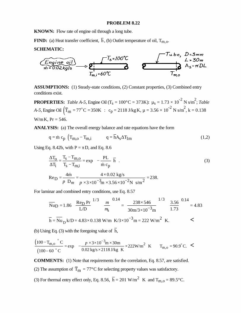
KNOWN: Flow rate of engine oil through a long tube.
FIND: (a) Heat transfer coefficient, h , (b) Outlet temperature of oil, Tm,o.
SCHEMATIC:
ASSUMPTIONS: (1) Steady-state conditions, (2) Constant properties, (3) Combined entryconditions exist.
PROPERTIES: Table A-5, Engine Oil (Ts = 100°C = 373K): µs = 1.73 × 10⁻²
N⋅s/m2; Table
A-5, Engine Oil ( )mT 77 C 350K := =o cp = 2118 J/kg⋅K, µ = 3.56 × 10⁻²
N⋅s/m2, k = 0.138
W/m⋅K, Pr = 546.
ANALYSIS: (a) The overall energy balance and rate equations have the form
( )p m,o m,i s 1mq m c T T q hA T= − = ∆& (1,2)
Using Eq. 8.42b, with P = πD, and Eq. 8.6
s m,oo
i s m,i p
T TT PLexp h .
T T T m c
−∆ = = − ⋅ ∆ − &(3)
D 3 2 24m 4 0.02 kg/s
Re 238. D 3 10 m 3.56 10 N s/mµπ π − −
×= = =× × × × ⋅
&
For laminar and combined entry conditions, use Eq. 8.57
0.14 1/31/3 0.14DD 3s
Re Pr 238 546 3.56Nu 1.86 4.83
L/D 1.7330m/3 10 m
µµ −
× = = = ×
D3 2h Nu k/D 4.83 0.138 W/m K/3 10 m 222 W/m K.−= = × ⋅ × = ⋅ <
(b) Using Eq. (3) with the foregoing value of h,
( )( )
3m,o 2
m,o100 T C 3 10 m 30m
exp 222W/m K T 90.9 C.0.02 kg/s 2118 J/kg K100 60 C
π −− × × ×= − × ⋅ =
× ⋅−
oo
o<
COMMENTS: (1) Note that requirements for the correlation, Eq. 8.57, are satisfied.
(2) The assumption of mT = 77°C for selecting property values was satisfactory.
(3) For thermal entry effect only, Eq. 8.56, 2h 201 W/m K= ⋅ and Tm,o = 89.5°C.
PROBLEM 8.23
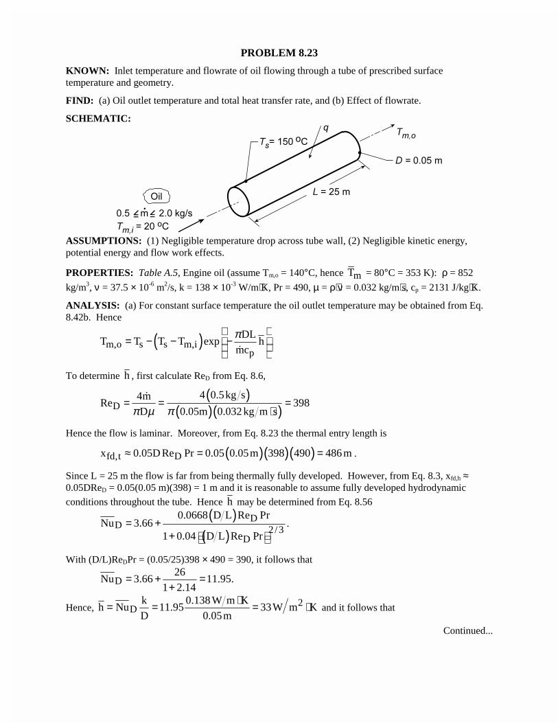
KNOWN: Inlet temperature and flowrate of oil flowing through a tube of prescribed surfacetemperature and geometry.
FIND: (a) Oil outlet temperature and total heat transfer rate, and (b) Effect of flowrate.
SCHEMATIC:
ASSUMPTIONS: (1) Negligible temperature drop across tube wall, (2) Negligible kinetic energy,potential energy and flow work effects.
PROPERTIES: Table A.5, Engine oil (assume Tm,o = 140°C, hence mT = 80°C = 353 K): ρ = 852
kg/m3, ν = 37.5 × 10⁻⁶ m2/s, k = 138 × 10-3 W/m⋅K, Pr = 490, µ = ρ⋅ν = 0.032 kg/m⋅s, cp = 2131 J/kg⋅K.
ANALYSIS: (a) For constant surface temperature the oil outlet temperature may be obtained from Eq.8.42b. Hence
( )m,o s s m,ip
DLT T T T exp h
mc
π = − − − �
To determine h , first calculate ReD from Eq. 8.6,
( )( )( )D
4 0.5kg s4mRe 398
D 0.05m 0.032 kg m sπ µ π= = =
⋅�
Hence the flow is laminar. Moreover, from Eq. 8.23 the thermal entry length is
( )( )( )fd,t Dx 0.05D Re Pr 0.05 0.05m 398 490 486 m≈ = = .
Since L = 25 m the flow is far from being thermally fully developed. However, from Eq. 8.3, xfd,h ≈0.05DReD = 0.05(0.05 m)(398) = 1 m and it is reasonable to assume fully developed hydrodynamic
conditions throughout the tube. Hence h may be determined from Eq. 8.56
( )( )
DD 2/3
D
0.0668 D L Re PrNu 3.66
1 0.04 D L Re Pr= +
+ .
With (D/L)ReDPr = (0.05/25)398 × 490 = 390, it follows that
D26
Nu 3.66 11.95.1 2.14
= + =+
Hence, 2D
k 0.138 W m Kh Nu 11.95 33W m K
D 0.05m
⋅= = = ⋅ and it follows that
Continued...
PROBLEM 8.23 (Cont.)
( ) ( )( ) 2m,o
0.05m 25mT 150 C 150 C 20 C exp 33W m K
0.5kg s 2131J kg K
π = − − − × ⋅ × ⋅
$ $ $
Tm,o = 35°C. <From the overall energy balance, Eq. 8.37, it follows that
( ) ( )p m,o m,iq mc T T 0.5kg s 2131J kg K 35 20 C= − = × ⋅ × − $
�
q = 15,980 W. <The value of Tm,o has been grossly overestimated in evaluating the properties. The properties should be
re-evaluated at T = (20 + 35)/2 = 27°C and the calculations repeated. Iteration should continue untilsatisfactory convergence is achieved between the calculated and assumed values of Tm,o. Following such
a procedure, one would obtain Tm,o = 36.4°C, ReD = 27.8, h = 32.8 W/m2⋅K, and q = 15,660 W. Thesmall effect of reevaluating the properties is attributed to the compensating effects on ReD (a largedecrease) and Pr (a large increase).
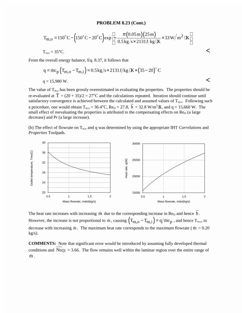
(b) The effect of flowrate on Tm,o and q was determined by using the appropriate IHT Correlations andProperties Toolpads.
0.5 1 1.5 2
Mass flowrate, mdot(kg/s)
20
24
28
32
36
40
Out
let t
empe
ratu
re, T
mo(
C)
0.5 1 1.5 2
Mass flowrate, mdot(kg/s)
15000
20000
25000
30000
Hea
t rat
e, q
(W)
The heat rate increases with increasing m� due to the corresponding increase in ReD and hence h .
However, the increase is not proportional to �m , causing ( )m,o m,i pT T q mc− = � , and hence Tm,o, to
decrease with increasing �m . The maximum heat rate corresponds to the maximum flowrate ( m� = 0.20kg/s).
COMMENTS: Note that significant error would be introduced by assuming fully developed thermal
conditions and DNu = 3.66. The flow remains well within the laminar region over the entire range ofm� .
PROBLEM 8.24
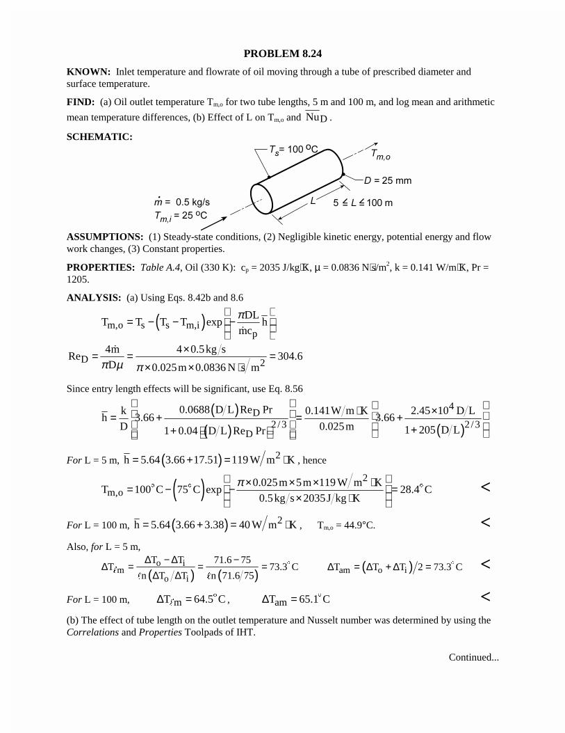
KNOWN: Inlet temperature and flowrate of oil moving through a tube of prescribed diameter andsurface temperature.
FIND: (a) Oil outlet temperature Tm,o for two tube lengths, 5 m and 100 m, and log mean and arithmetic
mean temperature differences, (b) Effect of L on Tm,o and DNu .
SCHEMATIC:
ASSUMPTIONS: (1) Steady-state conditions, (2) Negligible kinetic energy, potential energy and flowwork changes, (3) Constant properties.
PROPERTIES: Table A.4, Oil (330 K): cp = 2035 J/kg⋅K, µ = 0.0836 N⋅s/m2, k = 0.141 W/m⋅K, Pr =1205.
ANALYSIS: (a) Using Eqs. 8.42b and 8.6
( )m,o s s m,ip
DLT T T T exp h
mc
π = − − − �
D 24m 4 0.5kg s
Re 304.6D 0.025m 0.0836 N s mπ µ π
×= = =× × ⋅
�
Since entry length effects will be significant, use Eq. 8.56
( )( ) ( )
4D
2/3 2 /3D
0.0688 D L Re Prk 0.141W m K 2.45 10 D Lh 3.66 3.66
D 0.025m 1 205 D L1 0.04 D L Re Pr
⋅ × = + = + + +
For L = 5 m, ( ) 2h 5.64 3.66 17.51 119 W m K= + = ⋅ , hence
( ) 2
m,o0.025m 5m 119 W m K
T 100 C 75 C exp 28.4 C0.5kg s 2035J kg K
π × × × ⋅ = − − = × ⋅
$ $ $ <
For L = 100 m, ( ) 2h 5.64 3.66 3.38 40 W m K= + = ⋅ , Tm,o = 44.9°C. <Also, for L = 5 m,
( ) ( )o i
mo i
T T 71.6 75T 73.3 C
n T T n 71.6 75
∆ − ∆ −∆ = = =
∆ ∆$
"" "
( )am o iT T T 2 73.3 C∆ = ∆ + ∆ = $ <
For L = 100 m, mT 64.5 C∆ = $" , amT 65.1 C∆ = $ <
(b) The effect of tube length on the outlet temperature and Nusselt number was determined by using theCorrelations and Properties Toolpads of IHT.
Continued...
PROBLEM 8.24 (Cont.)
0 20 40 60 80 100
Tube length, L(m)
25
30
35
40
45
50
Out
let t
empe
ratu
re, T
mo(
C)
0 20 40 60 80 100
Tube length, L(m)
0
5
10
15
20
25
Nus
selt
num
ber,
NuD
bar
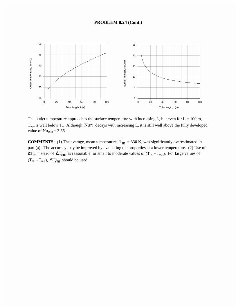
The outlet temperature approaches the surface temperature with increasing L, but even for L = 100 m,
Tm,o is well below Ts. Although DNu decays with increasing L, it is still well above the fully developedvalue of NuD,fd = 3.66.
COMMENTS: (1) The average, mean temperature, mT = 330 K, was significantly overestimated inpart (a). The accuracy may be improved by evaluating the properties at a lower temperature. (2) Use of∆Tam instead of mT∆ " is reasonable for small to moderate values of (Tm,i - Tm,o). For large values of
(Tm,i - Tm,o), mT∆ " should be used.
PROBLEM 8.25
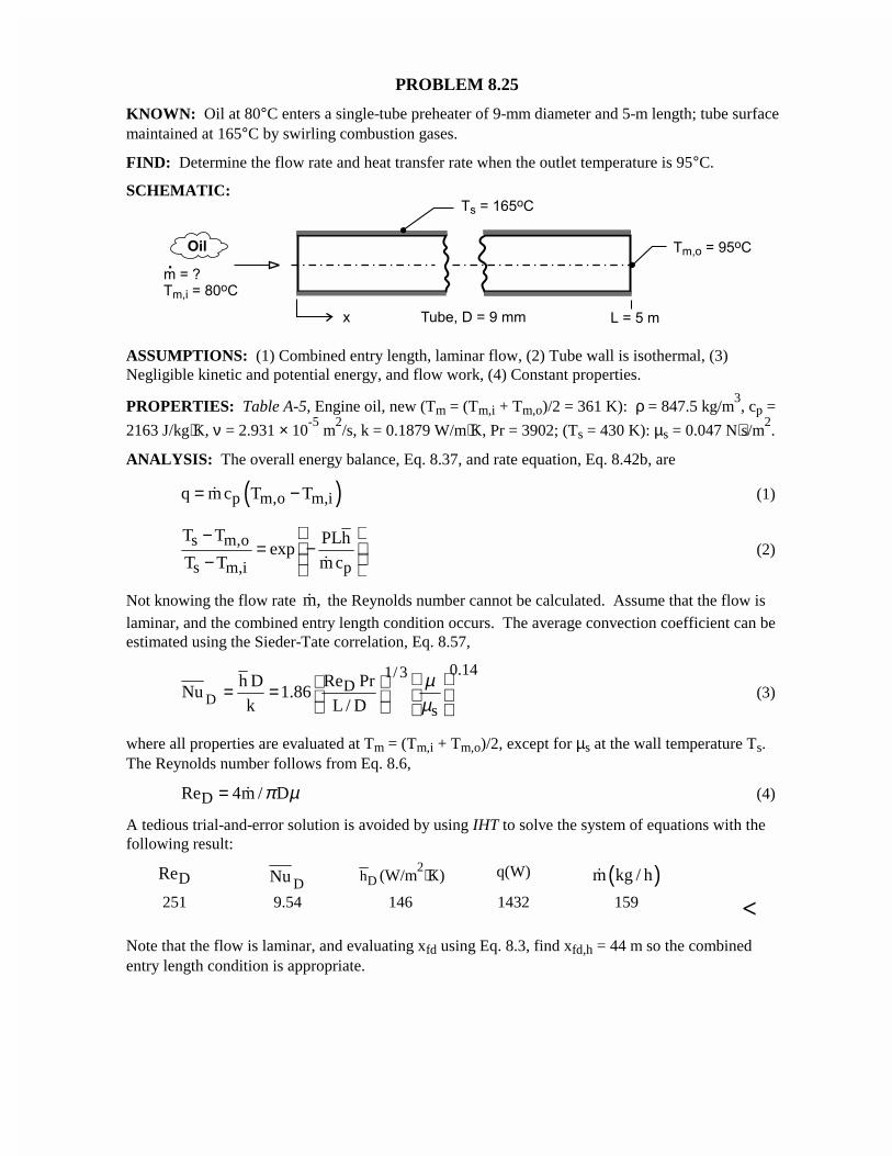
KNOWN: Oil at 80°C enters a single-tube preheater of 9-mm diameter and 5-m length; tube surfacemaintained at 165°C by swirling combustion gases.
FIND: Determine the flow rate and heat transfer rate when the outlet temperature is 95°C.
SCHEMATIC:
ASSUMPTIONS: (1) Combined entry length, laminar flow, (2) Tube wall is isothermal, (3)Negligible kinetic and potential energy, and flow work, (4) Constant properties.
PROPERTIES: Table A-5, Engine oil, new (Tm = (Tm,i + Tm,o)/2 = 361 K): ρ = 847.5 kg/m3, cp =
2163 J/kg⋅K, ν = 2.931 × 10⁻⁵
m2/s, k = 0.1879 W/m⋅K, Pr = 3902; (Ts = 430 K): µs = 0.047 N⋅s/m
2.
ANALYSIS: The overall energy balance, Eq. 8.37, and rate equation, Eq. 8.42b, are
( )p m,o m,iq m c T T= −� (1)
s m,o
s m,i p
T T PLhexp
T T m c
−= − − �
(2)
Not knowing the flow rate m,� the Reynolds number cannot be calculated. Assume that the flow islaminar, and the combined entry length condition occurs. The average convection coefficient can beestimated using the Sieder-Tate correlation, Eq. 8.57,
D
0.141/3D
s
h D Re PrNu 1.86
k L / D
µµ
= = (3)
where all properties are evaluated at Tm = (Tm,i + Tm,o)/2, except for µs at the wall temperature Ts.The Reynolds number follows from Eq. 8.6,
DRe 4m / Dπ µ= � (4)
A tedious trial-and-error solution is avoided by using IHT to solve the system of equations with thefollowing result:
DReDNu Dh (W/m
2⋅K) q(W) ( )m kg / h�
251 9.54 146 1432 159 <
Note that the flow is laminar, and evaluating xfd using Eq. 8.3, find xfd,h = 44 m so the combinedentry length condition is appropriate.
PROBLEM 8.26
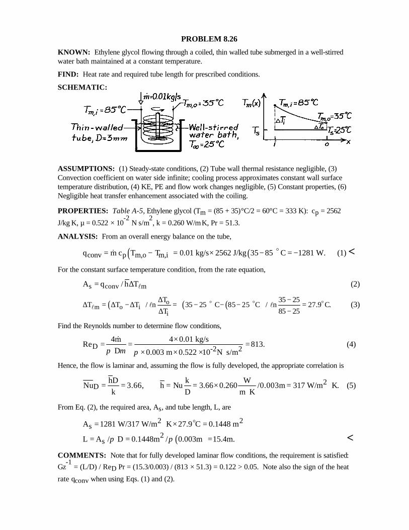
KNOWN: Ethylene glycol flowing through a coiled, thin walled tube submerged in a well-stirredwater bath maintained at a constant temperature.
FIND: Heat rate and required tube length for prescribed conditions.
SCHEMATIC:
ASSUMPTIONS: (1) Steady-state conditions, (2) Tube wall thermal resistance negligible, (3)Convection coefficient on water side infinite; cooling process approximates constant wall surfacetemperature distribution, (4) KE, PE and flow work changes negligible, (5) Constant properties, (6)Negligible heat transfer enhancement associated with the coiling.
PROPERTIES: Table A-5, Ethylene glycol (Tm = (85 + 35)°C/2 = 60°C = 333 K): cp = 2562
J/kg⋅K, µ = 0.522 × 10⁻²
N⋅s/m2, k = 0.260 W/m⋅K, Pr = 51.3.
ANALYSIS: From an overall energy balance on the tube,
( ) ( )conv p m,o m,iq m c T T 0.01 kg/s 2562 J/kg 35 85 C 1281 W.= − = × − = −o& (1) <For the constant surface temperature condition, from the rate equation,
s conv mA q / h T= ∆ l (2)
( ) ( ) ( )om o i
i
T 35 25T T T / n 35 25 C 85 25 C / n 27.9 C.
T 85 25
∆ −∆ = ∆ −∆ = − − − =
∆ −
o o ol l l (3)
Find the Reynolds number to determine flow conditions,
D -2 24m 4 0.01 kg/s
Re 813. D 0.003 m 0.522 10 N s/mπ µ π
×= = =× × × ⋅
&(4)
Hence, the flow is laminar and, assuming the flow is fully developed, the appropriate correlation is
2D
hD k WNu 3.66, h Nu 3.66 0.260 /0.003m 317 W/m K.
k D m K= = = = × = ⋅
⋅(5)
From Eq. (2), the required area, As, and tube length, L, are
2 2sA 1281 W/317 W/m K 27.9 C 0.1448 m= ⋅ × =o
( )2sL A / D 0.1448m / 0.003m 15.4m.π π= = = <
COMMENTS: Note that for fully developed laminar flow conditions, the requirement is satisfied:
Gz-1
= (L/D) / ReD Pr = (15.3/0.003) / (813 × 51.3) = 0.122 > 0.05. Note also the sign of the heat
rate qconv when using Eqs. (1) and (2).
PROBLEM 8.27
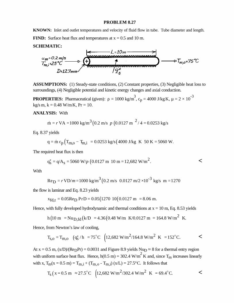
KNOWN: Inlet and outlet temperatures and velocity of fluid flow in tube. Tube diameter and length.
FIND: Surface heat flux and temperatures at x = 0.5 and 10 m.
SCHEMATIC:
ASSUMPTIONS: (1) Steady-state conditions, (2) Constant properties, (3) Negligible heat loss tosurroundings, (4) Negligible potential and kinetic energy changes and axial conduction.
PROPERTIES: Pharmaceutical (given): ρ = 1000 kg/m3, cp = 4000 J/kg⋅K, µ = 2 × 10
-3
kg/s⋅m, k = 0.48 W/m⋅K, Pr = 10.
ANALYSIS: With
( ) ( )23m VA 1000 kg/m 0.2 m/s 0.0127 m / 4 0.0253 kg/sρ π= = =&
Eq. 8.37 yields
( ) ( )p m,o m,iq m c T T 0.0253 kg/s 4000 J/kg K 50 K 5060 W.= − = ⋅ =&
The required heat flux is then
( ) 2s sq q/A 5060 W/ 0.0127 m 10 m 12,682 W/m .π′′ = = = <
With
( )3 -3DRe VD/ 1000 kg/m 0.2 m/s 0.0127 m/2 10 kg/s m 1270ρ µ= = × ⋅ =
the flow is laminar and Eq. 8.23 yields
( ) ( )fd,t Dx 0.05Re PrD 0.05 1270 10 0.0127 m 8.06 m.= = =
Hence, with fully developed hydrodynamic and thermal conditions at x = 10 m, Eq. 8.53 yields
( ) ( ) ( ) 2D,fdh 10 m Nu k/D 4.36 0.48 W/m K/0.0127 m 164.8 W/m K.= = ⋅ = ⋅
Hence, from Newton’s law of cooling,
( ) ( )2 2s,o m,o sT T q / h 75 C 12,682 W/m /164.8 W/m K 152 C.′′= + = + ⋅ =o o <
At x = 0.5 m, (x/D)/(ReDPr) = 0.0031 and Figure 8.9 yields NuD ≈ 8 for a thermal entry region
with uniform surface heat flux. Hence, h(0.5 m) = 302.4 W/m2⋅K and, since Tm increases linearly
with x, Tm(x = 0.5 m) = Tm,i + (Tm,o - Tm,i) (x/L) = 27.5°C. It follows that
( ) ( )2 2sT x 0.5 m 27.5 C 12,682 W/m /302.4 W/m K 69.4 C.= ≈ + ⋅ =o o <
PROBLEM 8.28
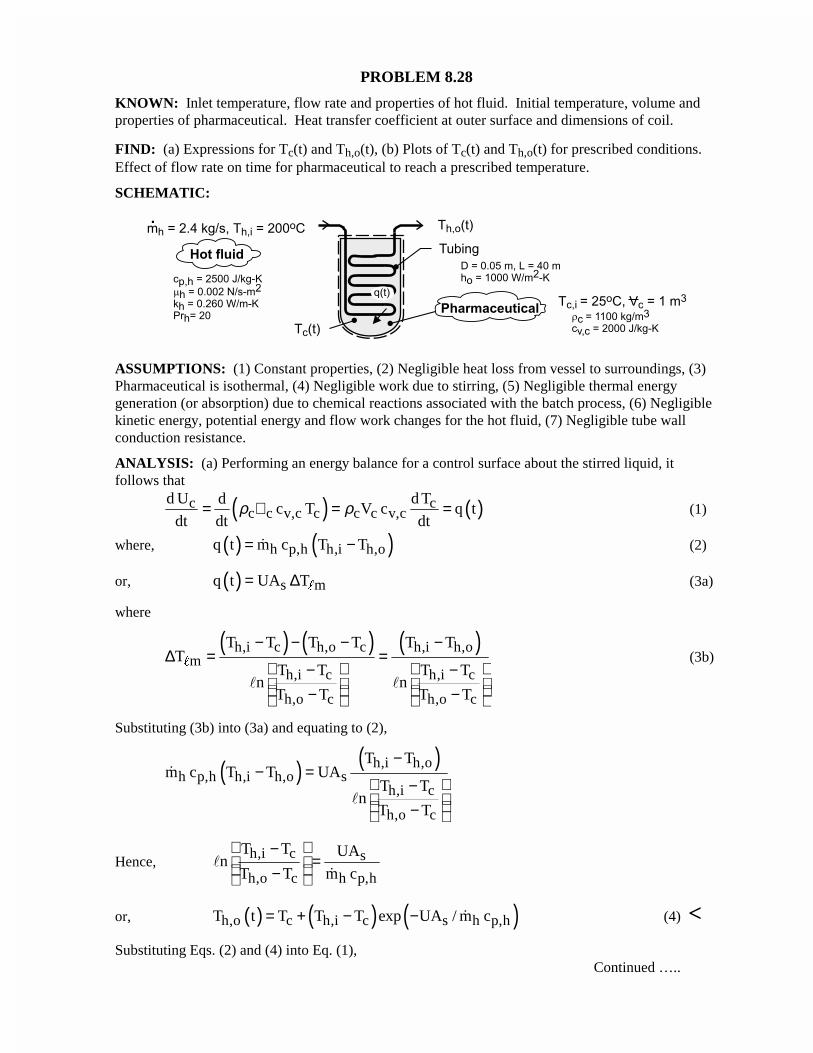
KNOWN: Inlet temperature, flow rate and properties of hot fluid. Initial temperature, volume andproperties of pharmaceutical. Heat transfer coefficient at outer surface and dimensions of coil.
FIND: (a) Expressions for Tc(t) and Th,o(t), (b) Plots of Tc(t) and Th,o(t) for prescribed conditions.Effect of flow rate on time for pharmaceutical to reach a prescribed temperature.
SCHEMATIC:
ASSUMPTIONS: (1) Constant properties, (2) Negligible heat loss from vessel to surroundings, (3)Pharmaceutical is isothermal, (4) Negligible work due to stirring, (5) Negligible thermal energygeneration (or absorption) due to chemical reactions associated with the batch process, (6) Negligiblekinetic energy, potential energy and flow work changes for the hot fluid, (7) Negligible tube wallconduction resistance.
ANALYSIS: (a) Performing an energy balance for a control surface about the stirred liquid, itfollows that
( ) ( )c cc c v,c c c c v,c
d U d Tdc T V c q t
dt dt dtρ ρ= ∀ = = (1)
where, ( ) ( )h p,h h,i h,oq t m c T T= −� (2)
or, ( ) s mq t UA T= ∆ " (3a)
where
( ) ( ) ( )h,i c h,o c h,i h,om
h,i c h,i c
h,o c h,o c
T T T T T TT
T T T Tn n
T T T T
− − − −∆ = =
− − − −
"
� �
(3b)
Substituting (3b) into (3a) and equating to (2),
( ) ( )h,i h,oh p,h h,i h,o s
h,i c
h,o c
T Tm c T T UA
T Tn
T T
−− =
− −
�
�
Hence,h,i c s
h,o c h p,h
T T UAn
T T m c
−= −
��
or, ( ) ( ) ( )h,o c h,i c s h p,hT t T T T exp UA / m c= + − − � (4) <Substituting Eqs. (2) and (4) into Eq. (1),
Continued …..
PROBLEM 8.28 (Cont.)
( ) ( )cc c v,c h p,h h,i c h,i c s h p,h
d Tc m c T T T T exp UA / m c
dtρ ∀ = − − − − � �
( ) ( )h p,h h,i ccs h p,h
c c v,c
m c T Td T1 exp UA / m c
dt cρ−
= − − ∀
�
�
( )( ) ( )c
c,i
T t th p,hcs h p,hT oc c v,cc h,i
m cd T1 exp UA / m c dt
cT T ρ − = − − ∀−∫ ∫
��
( )h p,hc h,is h p,h
c,i h,i c c v,c
m cT Tn 1 exp UA / m c t
T T V cρ − − = − − −
���
( ) ( ) ( )h p,h h p,hc h,i h,i c,i
c c v,c
m c 1 exp UA / m c tT t T T T exp
cρ
− − = − − − ∀
� �
(5) <
Eq. (5) may be used to determine Tc(t) and the result used with (4) to determine Th,o(t).
(b) To evaluate the temperature histories, the overall heat transfer coefficient, ( ) 11 1
o iU h h ,−− −
= + must
first be determined. With ( ) 2DRe 4 m / D 4 2.4 kg / s / 0.05m 0.002 N s / m 30, 600,π µ π= = × ⋅ =� the flow
is turbulent and
( ) ( )4 /5 0.3 2i D
k 0.260 W / m Kh Nu 0.023 30,600 20 1140 W / m K
D 0.05m
⋅ = = = ⋅
Hence, ( ) ( )1 2 21 1U 1000 1140 W / m K 532 W / m K.
−− −= + ⋅ = ⋅ As shown below, the temperature of
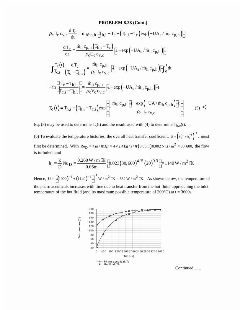
the pharmaceuticals increases with time due to heat transfer from the hot fluid, approaching the inlettemperature of the hot fluid (and its maximum possible temperature of 200°C) at t = 3600s.
Continued …..
0 400 800 1200 1600 2000 2400 2800 3200 3600
Tim e (s )
20
40
60
80
100
120
140
160
180
200
Te
mp
era
ture
(C)
P ha rm aceu tica l, TcH o t flu id , Th
PROBLEM 8.28 (Cont.)
With increasing Tc, the rate of heat transfer from the hot fluid decreases (from 4.49 × 10⁵ W at t = 0
to 6760 W at 3600s), in which case Th,o increases (from 125.2°C at t = 0 to 198.9°C at 3600s). The
time required for the pharmaceuticals to reach a temperature of Tc = 160°C is
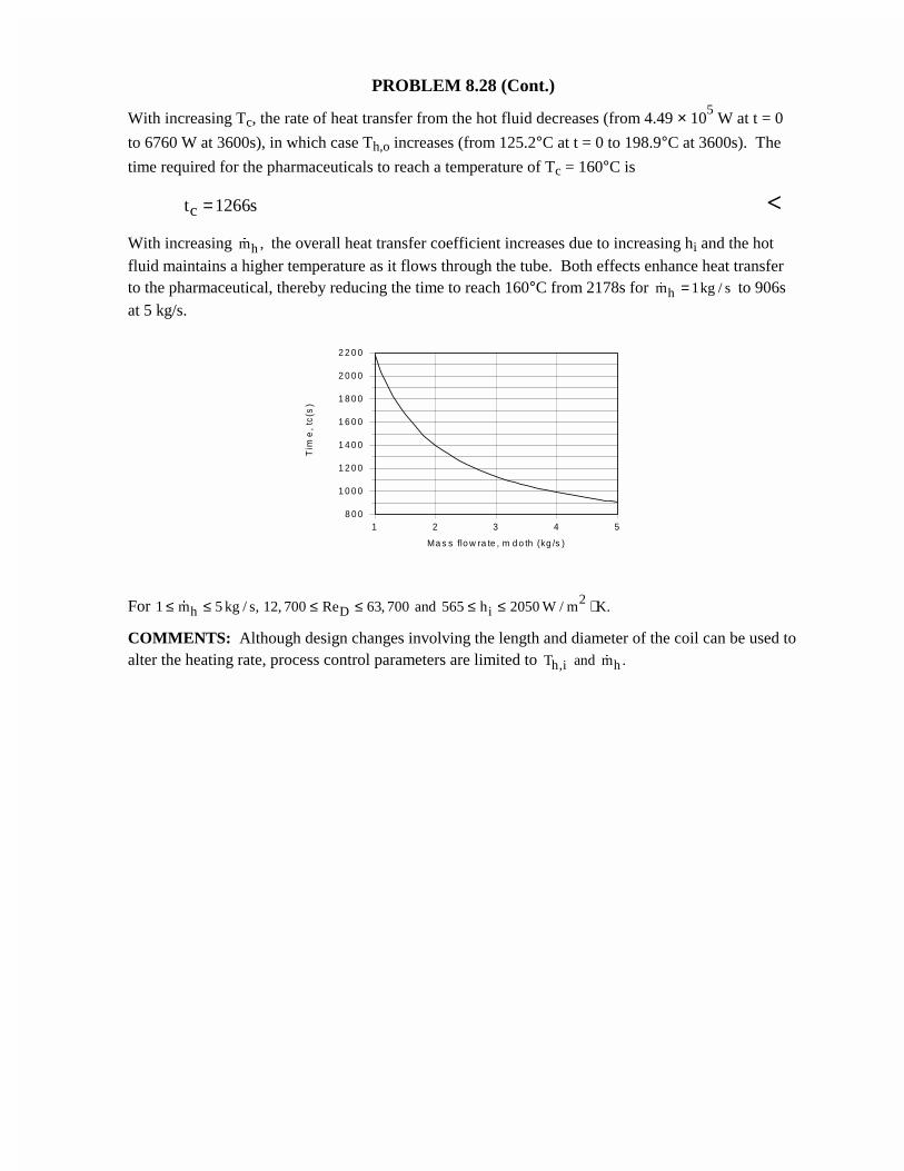
ct 1266s= <With increasing hm ,� the overall heat transfer coefficient increases due to increasing hi and the hotfluid maintains a higher temperature as it flows through the tube. Both effects enhance heat transferto the pharmaceutical, thereby reducing the time to reach 160°C from 2178s for hm 1kg / s=� to 906sat 5 kg/s.
For 2h D i1 m 5 kg / s, 12, 700 Re 63, 700 and 565 h 2050 W / m K.≤ ≤ ≤ ≤ ≤ ≤ ⋅�
COMMENTS: Although design changes involving the length and diameter of the coil can be used toalter the heating rate, process control parameters are limited to h,i hT and m .�
1 2 3 4 5
Ma s s flo w ra te , m d o th (kg /s )
8 0 0
1 0 0 0
1 2 0 0
1 4 0 0
1 6 0 0
1 8 0 0
2 0 0 0
2 2 0 0
Tim
e,
tc(s
)
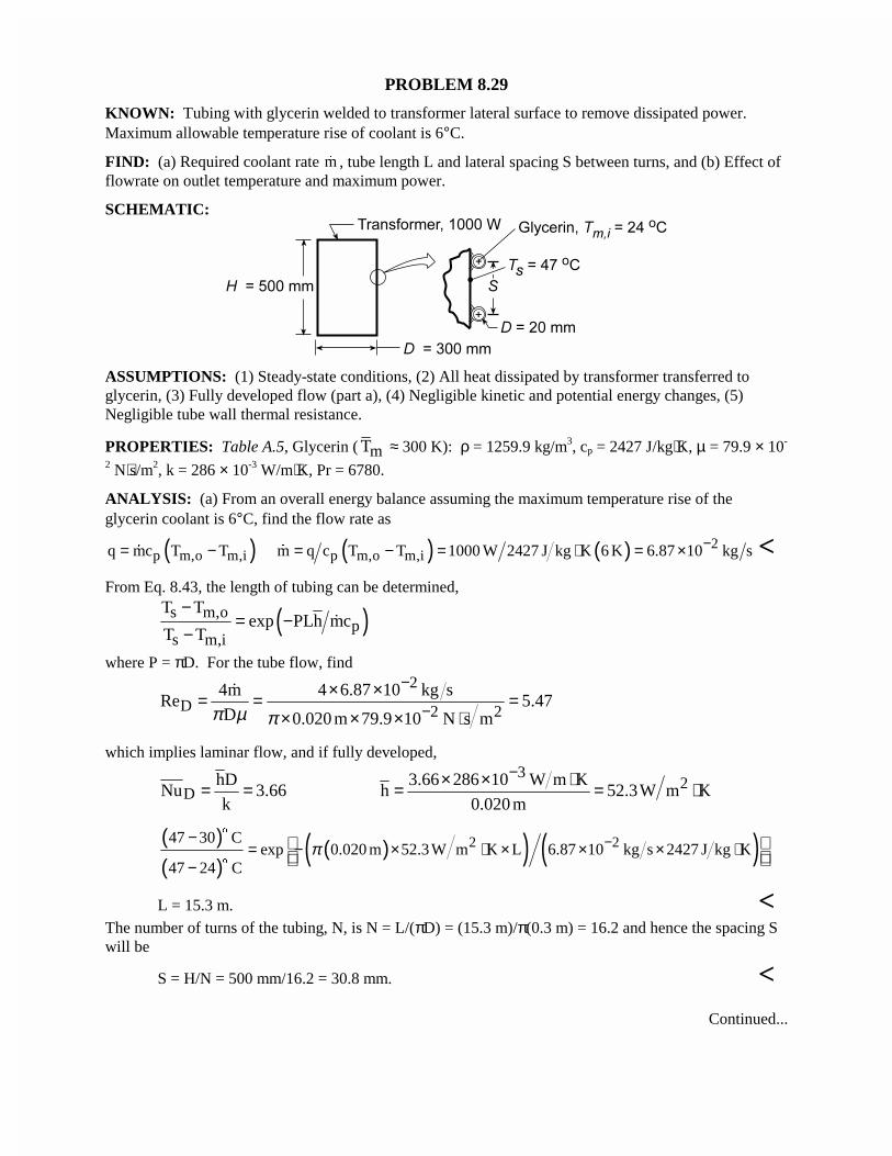
PROBLEM 8.29
KNOWN: Tubing with glycerin welded to transformer lateral surface to remove dissipated power.Maximum allowable temperature rise of coolant is 6°C.
FIND: (a) Required coolant rate �m , tube length L and lateral spacing S between turns, and (b) Effect offlowrate on outlet temperature and maximum power.
SCHEMATIC:
ASSUMPTIONS: (1) Steady-state conditions, (2) All heat dissipated by transformer transferred toglycerin, (3) Fully developed flow (part a), (4) Negligible kinetic and potential energy changes, (5)Negligible tube wall thermal resistance.
PROPERTIES: Table A.5, Glycerin ( mT ≈ 300 K): ρ = 1259.9 kg/m3, cp = 2427 J/kg⋅K, µ = 79.9 × 10-
2 N⋅s/m2, k = 286 × 10-3 W/m⋅K, Pr = 6780.
ANALYSIS: (a) From an overall energy balance assuming the maximum temperature rise of theglycerin coolant is 6°C, find the flow rate as
( )p m,o m,iq mc T T= −� ( ) ( ) 2p m,o m,im q c T T 1000 W 2427 J kg K 6 K 6.87 10 kg s−= − = ⋅ = ×� <
From Eq. 8.43, the length of tubing can be determined,
( )s m,op
s m,i
T Texp PLh mc
T T
−= −
−�
where P = πD. For the tube flow, find2
D 2 24m 4 6.87 10 kg s
Re 5.47D 0.020 m 79.9 10 N s mπ µ π
−
−× ×= = =
× × × ⋅
�
which implies laminar flow, and if fully developed,
DhD
Nu 3.66k
= = 3
23.66 286 10 W m Kh 52.3W m K
0.020 m
−× × ⋅= = ⋅
( )( )
( )( ) ( )2 247 30 Cexp 0.020 m 52.3W m K L 6.87 10 kg s 2427 J kg K
47 24 Cπ −−
= − × ⋅ × × × ⋅−
$
$
L = 15.3 m. <The number of turns of the tubing, N, is N = L/(πD) = (15.3 m)/π(0.3 m) = 16.2 and hence the spacing Swill be
S = H/N = 500 mm/16.2 = 30.8 mm. <Continued...
PROBLEM 8.29 (Cont.)
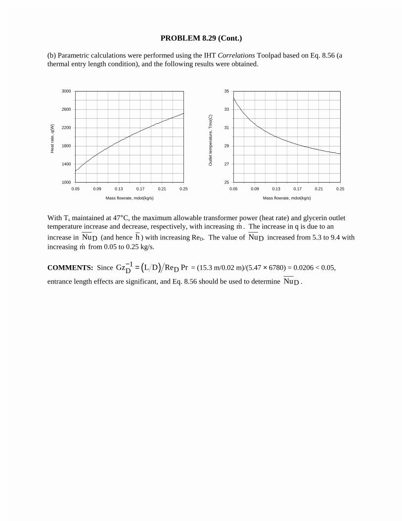
(b) Parametric calculations were performed using the IHT Correlations Toolpad based on Eq. 8.56 (athermal entry length condition), and the following results were obtained.
0.05 0.09 0.13 0.17 0.21 0.25
Mass flowrate, mdot(kg/s)
1000
1400
1800
2200
2600
3000
Hea
t rat
e, q
(W)
0.05 0.09 0.13 0.17 0.21 0.25
Mass flowrate, mdot(kg/s)
25
27
29
31
33
35
Out
let t
empe
ratu
re, T
mo(
C)
With Ts maintained at 47°C, the maximum allowable transformer power (heat rate) and glycerin outlettemperature increase and decrease, respectively, with increasing �m . The increase in q is due to an
increase in DNu (and hence h ) with increasing ReD. The value of DNu increased from 5.3 to 9.4 withincreasing �m from 0.05 to 0.25 kg/s.
COMMENTS: Since ( )1DDGz L D Re Pr− = = (15.3 m/0.02 m)/(5.47 × 6780) = 0.0206 < 0.05,
entrance length effects are significant, and Eq. 8.56 should be used to determine DNu .
PROBLEM 8.30
KNOWN: Diameter and length of copper tubing. Temperature of collector plate to which tubing issoldered. Water inlet temperature and flow rate.
FIND: (a) Water outlet temperature and heat rate, (b) Variation of outlet temperature and heat rate withflow rate. Variation of water temperature along tube for the smallest and largest flowrates.
SCHEMATIC:
ASSUMPTIONS: (1) Straight tube with smooth surface, (2) Negligible kinetic/potential energy andflow work changes, (3) Negligible thermal resistance between plate and tube inner surface, (4) ReD,c =2300.
PROPERTIES: Table A.6, water (assume mT = (Tm,i + Ts)/2 = 47.5°C = 320.5 K): ρ = 986 kg/m3, cp =
4180 J/kg⋅K, µ = 577 × 10-6 N⋅s/m2, k = 0.640 W/m⋅K, Pr = 3.77. Table A.6, water (Ts = 343 K): µs =400 × 10-6 N⋅s/m2.
ANALYSIS: (a) For �m = 0.01 kg/s, ReD = 4 m Dπ µ� = 4(0.01 kg/s)/π(0.01 m)577 × 10-6 N⋅s/m2 =
2200, in which case the flow may be assumed to be laminar. With fd,tx D ≈ 0.05ReDPr =
0.05(2200)(3.77) = 415 and L/D = 800, the flow is fully developed over approximately 50% of the tube
length. With ( ) ( )1/3 0.14D sRe Pr L D µ µ = 2.30, Eq. 8.57 may therefore be used to compute the
average convection coefficient
0.141/3D
Ds
Re PrNu 1.86 4.27
L D
µµ
= =
( ) ( ) 2Dh k D Nu 4.27 0.640 W m K 0.01m 273W m K= = ⋅ = ⋅
From Eq. 8.42b,
2s m,o
s m,i p
T T DL 0.01m 8m 273W m Kexp h exp
T T mc 0.01kg s 4180J kg K
π π − × × × ⋅ = − = − − × ⋅ �
( )m,o s s m,iT T 0.194 T T 70 C 8.7 C 61.3 C= − − = − =$ $ $ <Hence, ( ) ( )( )p m,o m,iq mc T T 0.01kg s 4186 J kg K 36.3K 1519 W= − = ⋅ =� <
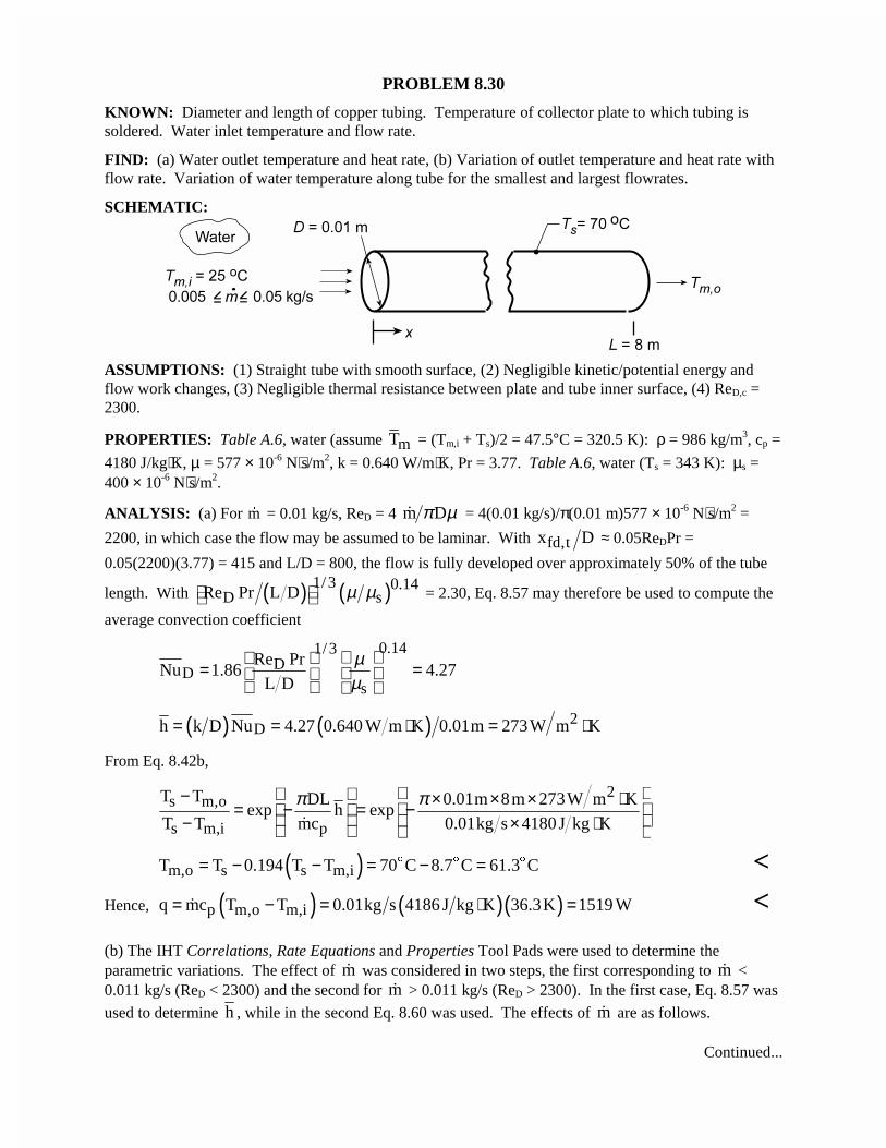
(b) The IHT Correlations, Rate Equations and Properties Tool Pads were used to determine theparametric variations. The effect of m� was considered in two steps, the first corresponding to m� <0.011 kg/s (ReD < 2300) and the second for m� > 0.011 kg/s (ReD > 2300). In the first case, Eq. 8.57 was
used to determine h , while in the second Eq. 8.60 was used. The effects of m� are as follows.
Continued...
PROBLEM 8.30 (Cont.)
0.005 0.006 0.007 0.008 0.009 0.01 0.011
Mass flowrate, mdot(kg/s)
60
61
62
63
64
65
66
67O
utle
t tem
pera
ture
, Tm
o(C
)
Laminar flow (ReD < 2300)
0.01 0.02 0.03 0.04 0.05
Mass flowrate, mdot(kg/s)
69
69.2
69.4
69.6
69.8
70
Out
let t
empe
ratu
re, T
mo(
C)
Turbulent flow (ReD>2300)
0.005 0.006 0.007 0.008 0.009 0.01 0.011
Mass flowrate, mdot(kg/s)
800
900
1000
1100
1200
1300
1400
1500
1600
1700
Hea
t rat
e, q
(W)
Laminar flow (ReD < 2300)
0.01 0.02 0.03 0.04 0.05
Mass flowrate, mdot(kg/s)
1500
3500
5500
7500
9500
Hea
t rat
e, q
(W)
Turbulent flow (ReD>2300)
The outlet temperature decreases with increasing m� , although the effect is more pronounced for laminarflow. If q were independent of �m , (Tm,o - Tm,i) would decrease inversely with increasing �m . In turbulent
flow, however, the convection coefficient, and hence the heat rate, increases approximately as 0.8m� ,
thereby attenuating the foregoing effect. In laminar flow, q ~ 0.5m� and this attenuation is not aspronounced.
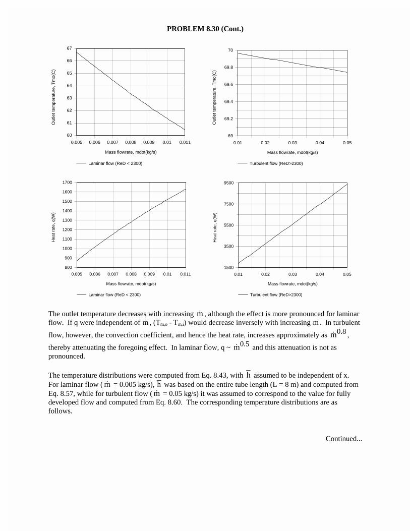
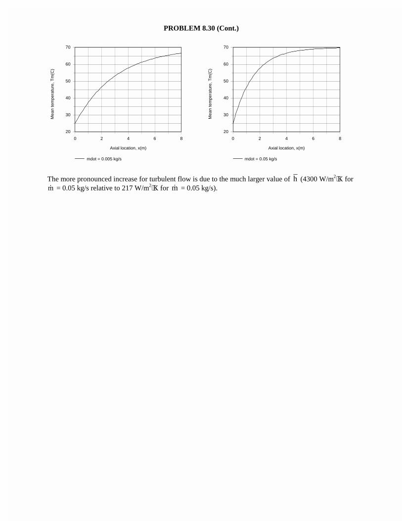
The temperature distributions were computed from Eq. 8.43, with h assumed to be independent of x.For laminar flow ( m� = 0.005 kg/s), h was based on the entire tube length (L = 8 m) and computed fromEq. 8.57, while for turbulent flow ( m� = 0.05 kg/s) it was assumed to correspond to the value for fullydeveloped flow and computed from Eq. 8.60. The corresponding temperature distributions are asfollows.
Continued...
PROBLEM 8.30 (Cont.)
0 2 4 6 8
Axial location, x(m)
20
30
40
50
60
70M
ean
tem
pera
ture
, Tm
(C)
mdot = 0.005 kg/s
0 2 4 6 8
Axial location, x(m)
20
30
40
50
60
70
Mea
n te
mpe
ratu
re, T
m(C
)
mdot = 0.05 kg/s
The more pronounced increase for turbulent flow is due to the much larger value of h (4300 W/m2⋅K for�m = 0.05 kg/s relative to 217 W/m2⋅K for m� = 0.05 kg/s).
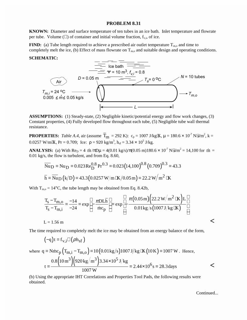
PROBLEM 8.31
KNOWN: Diameter and surface temperature of ten tubes in an ice bath. Inlet temperature and flowrateper tube. Volume (∀ ) of container and initial volume fraction, fv,i, of ice.
FIND: (a) Tube length required to achieve a prescribed air outlet temperature Tm,o and time tocompletely melt the ice, (b) Effect of mass flowrate on Tm,o and suitable design and operating conditions.
SCHEMATIC:
ASSUMPTIONS: (1) Steady-state, (2) Negligible kinetic/potential energy and flow work changes, (3)Constant properties, (4) Fully developed flow throughout each tube, (5) Negligible tube wall thermalresistance.
PROPERTIES: Table A.4, air (assume mT = 292 K): cp = 1007 J/kg⋅K, µ = 180.6 × 10⁻⁷ N⋅s/m2, k =
0.0257 W/m⋅K, Pr = 0.709; Ice: ρ = 920 kg/m3, hsf = 3.34 × 10⁵ J/kg.
ANALYSIS: (a) With ReD = 4 m� /πDµ = 4(0.01 kg/s)/π(0.05 m)180.6 × 10⁻⁷ N⋅s/m2 = 14,100 for m� =0.01 kg/s, the flow is turbulent, and from Eq. 8.60,
( ) ( )0.8 0.30.8 0.3D D DNu Nu 0.023Re Pr 0.023 14,100 0.709 43.3= = = =
( ) ( ) 2Dh Nu k D 43.3 0.0257 W m K 0.05m 22.2 W m K= = ⋅ = ⋅
With Tm,o = 14°C, the tube length may be obtained from Eq. 8.42b,
( )( )( )
2s m,o
s m,i p
0.05m 22.2 W m K LT T 14 DLhexp exp
T T 24 mc 0.01kg s 1007 J kg K
ππ ⋅ − − = = − = − − − ⋅
�
L = 1.56 m <The time required to completely melt the ice may be obtained from an energy balance of the form,
( ) ( )v,i sfq t f hρ− = ∀
where ( ) ( ) ( )p m,i m,oq Nmc T T 10 0.01kg s 1007 J kg K 10K 1007 W= − = ⋅ =� . Hence,
( )( )3 3 56
0.8 10 m 920 kg m 3.34 10 J kgt 2.44 10 s 28.3days
1007 W
×= = × = <
(b) Using the appropriate IHT Correlations and Properties Tool Pads, the following results wereobtained.
Continued...
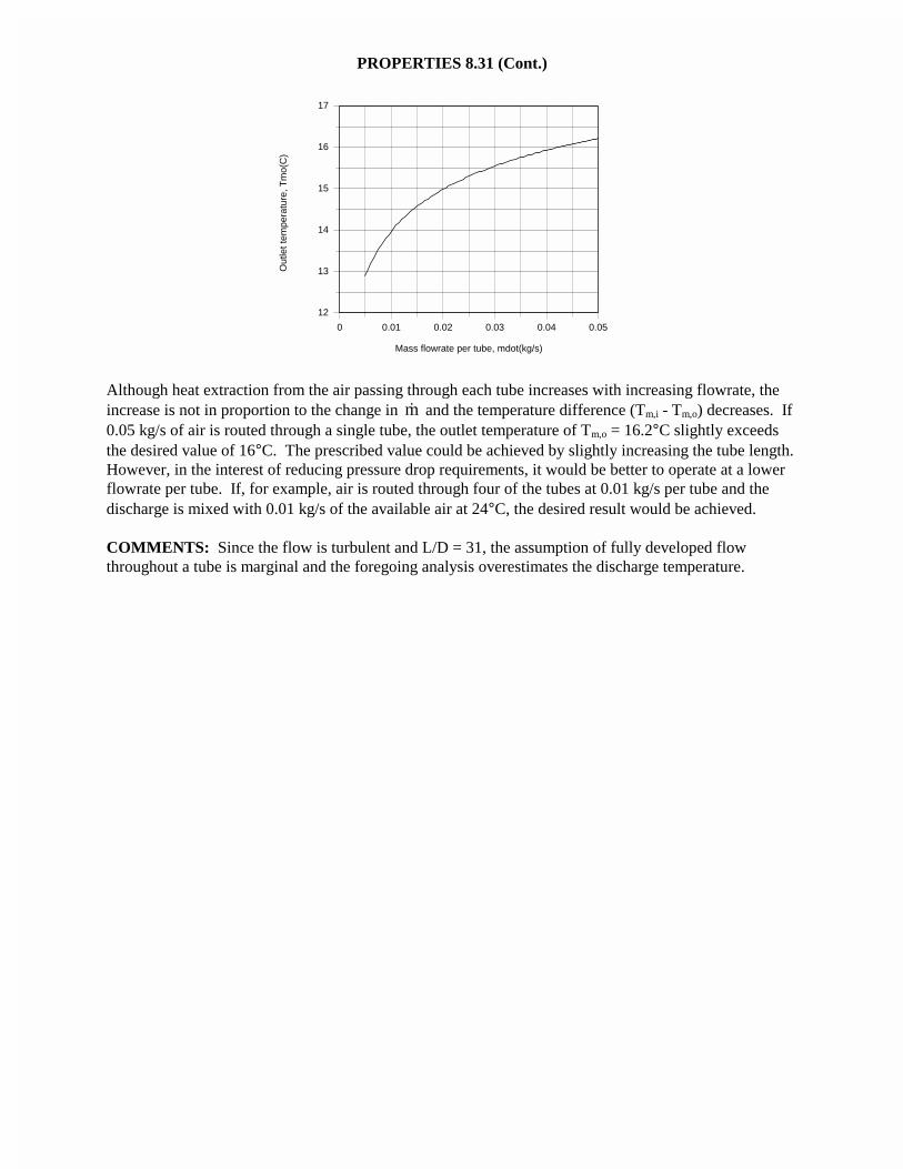
PROPERTIES 8.31 (Cont.)
0 0.01 0.02 0.03 0.04 0.05
Mass flowrate per tube, mdot(kg/s)
12
13
14
15
16
17
Out
let t
empe
ratu
re, T
mo(
C)
Although heat extraction from the air passing through each tube increases with increasing flowrate, theincrease is not in proportion to the change in m� and the temperature difference (Tm,i - Tm,o) decreases. If0.05 kg/s of air is routed through a single tube, the outlet temperature of Tm,o = 16.2°C slightly exceedsthe desired value of 16°C. The prescribed value could be achieved by slightly increasing the tube length.However, in the interest of reducing pressure drop requirements, it would be better to operate at a lowerflowrate per tube. If, for example, air is routed through four of the tubes at 0.01 kg/s per tube and thedischarge is mixed with 0.01 kg/s of the available air at 24°C, the desired result would be achieved.
COMMENTS: Since the flow is turbulent and L/D = 31, the assumption of fully developed flowthroughout a tube is marginal and the foregoing analysis overestimates the discharge temperature.
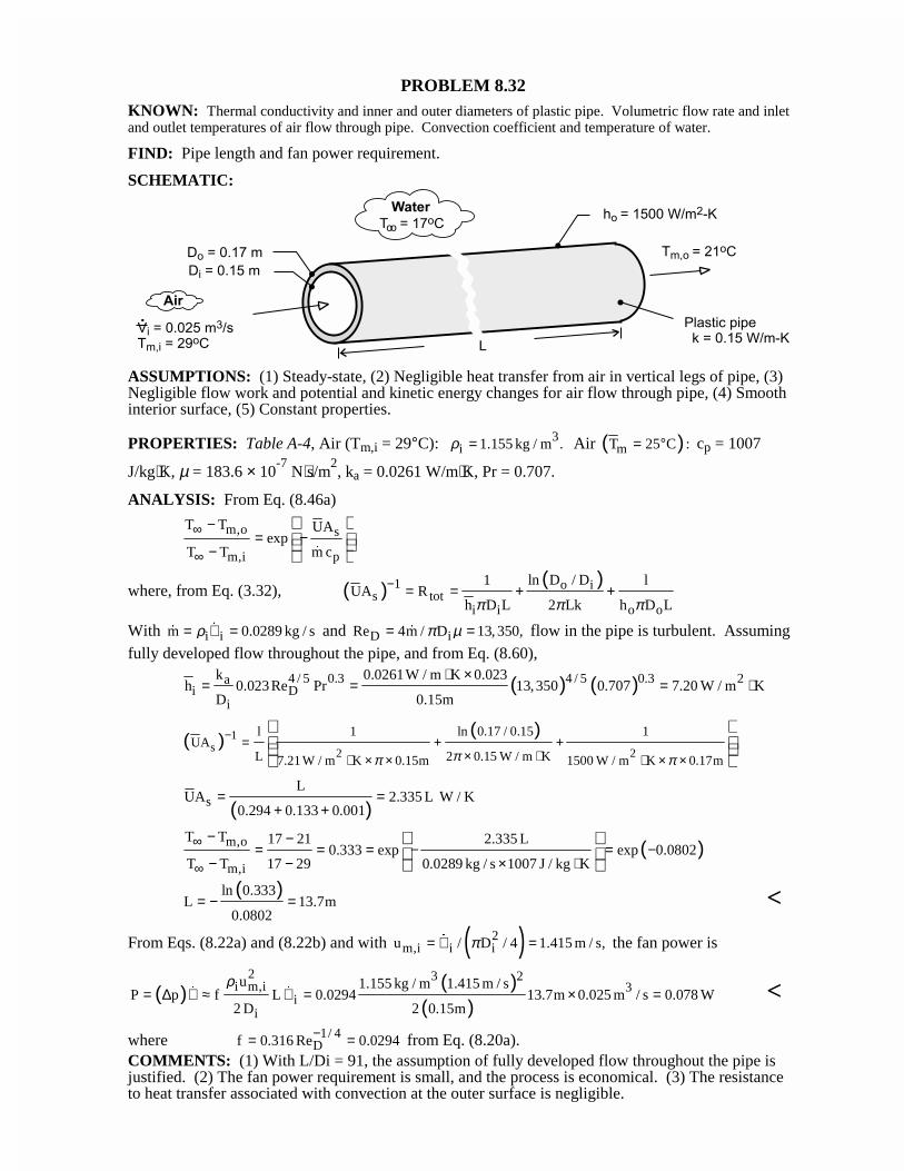
PROBLEM 8.32KNOWN: Thermal conductivity and inner and outer diameters of plastic pipe. Volumetric flow rate and inletand outlet temperatures of air flow through pipe. Convection coefficient and temperature of water.
FIND: Pipe length and fan power requirement.
SCHEMATIC:
ASSUMPTIONS: (1) Steady-state, (2) Negligible heat transfer from air in vertical legs of pipe, (3)Negligible flow work and potential and kinetic energy changes for air flow through pipe, (4) Smoothinterior surface, (5) Constant properties.
PROPERTIES: Table A-4, Air (Tm,i = 29°C): 3i 1.155 kg / m .ρ = Air ( )mT 25 C := ° cp = 1007
J/kg⋅K, µ = 183.6 × 10⁻⁷
N⋅s/m2, ka = 0.0261 W/m⋅K, Pr = 0.707.
ANALYSIS: From Eq. (8.46a)
m,o s
m,i p
T T UAexp
T T m c
∞
∞
−= −
−
�
where, from Eq. (3.32), ( ) ( )1 o is tot
i i o o
ln D / D1 lUA R
h D L 2 Lk h D Lπ π π− = = + +
With i im 0.0289 kg / sρ= ∀ =�
� and D iRe 4m / D 13, 350,π µ= =� flow in the pipe is turbulent. Assumingfully developed flow throughout the pipe, and from Eq. (8.60),
( ) ( )4 / 5 0.3 24 / 5 0.3ai D
i
k 0.0261W / m K 0.023h 0.023 Re Pr 13,350 0.707 7.20 W / m K
D 0.15m
⋅ ×= = = ⋅
( ) ( )1s 2 2
l 1 ln 0.17 / 0.15 1UA
L 2 0.15 W / m K7.21 W / m K 0.15m 1500 W / m K 0.17mππ π
− = + +× ⋅⋅ × × ⋅ × ×
( )sL
UA 2.335 L W / K0.294 0.133 0.001
= =+ +
( )m,o
m,i
T T 17 21 2.335 L0.333 exp exp 0.0802
T T 17 29 0.0289 kg / s 1007 J / kg K
∞
∞
− −= = = − = −
− − × ⋅
( )ln 0.333L 13.7m
0.0802= − = <
From Eqs. (8.22a) and (8.22b) and with ( )2m,i i iu / D / 4 1.415 m / s,π= ∀ =� the fan power is
( ) ( )( )
2 3 2i m,i 3
ii
u 1.155 kg / m 1.415 m / sP p f L 0.0294 13.7m 0.025 m / s 0.078 W
2 D 2 0.15m
ρ= ∆ ∀ ≈ ∀ = × =� � <
where 1/ 4Df 0.316 Re 0.0294−= = from Eq. (8.20a).
COMMENTS: (1) With L/Di = 91, the assumption of fully developed flow throughout the pipe isjustified. (2) The fan power requirement is small, and the process is economical. (3) The resistanceto heat transfer associated with convection at the outer surface is negligible.
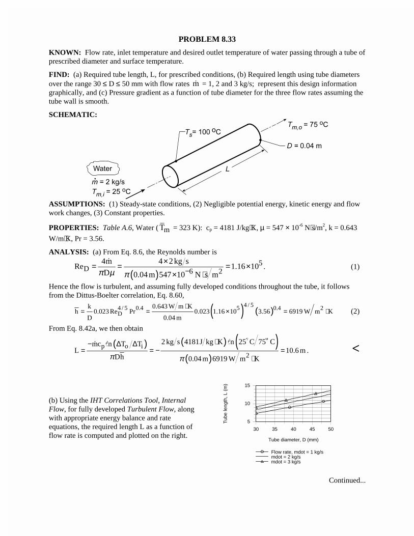
PROBLEM 8.33
KNOWN: Flow rate, inlet temperature and desired outlet temperature of water passing through a tube ofprescribed diameter and surface temperature.
FIND: (a) Required tube length, L, for prescribed conditions, (b) Required length using tube diametersover the range 30 ≤ D ≤ 50 mm with flow rates m� = 1, 2 and 3 kg/s; represent this design informationgraphically, and (c) Pressure gradient as a function of tube diameter for the three flow rates assuming thetube wall is smooth.
SCHEMATIC:
ASSUMPTIONS: (1) Steady-state conditions, (2) Negligible potential energy, kinetic energy and flowwork changes, (3) Constant properties.
PROPERTIES: Table A.6, Water ( mT = 323 K): cp = 4181 J/kg⋅K, µ = 547 × 10-6 N⋅s/m2, k = 0.643
W/m⋅K, Pr = 3.56.
ANALYSIS: (a) From Eq. 8.6, the Reynolds number is
( )5
D 6 24m 4 2 kg s
Re 1.16 10D 0.04 m 547 10 N s mπ µ π −
×= = = ×× ⋅
�. (1)
Hence the flow is turbulent, and assuming fully developed conditions throughout the tube, it followsfrom the Dittus-Boelter correlation, Eq. 8.60,
( ) ( )4 / 54 / 5 0.4 5 20.4
Dk 0.643 W m K
h 0.023 Re Pr 0.023 1.16 10 3.56 6919 W m KD 0.04 m
⋅= = × = ⋅ (2)
From Eq. 8.42a, we then obtain
( ) ( ) ( )( )
p o i2
2 kg s 4181J kg K n 25 C 75 Cmc n T TL 10.6 m
Dh 0.04 m 6919 W m Kπ π
⋅− ∆ ∆= = − =
⋅
$ $
"� "
. <
(b) Using the IHT Correlations Tool, InternalFlow, for fully developed Turbulent Flow, alongwith appropriate energy balance and rateequations, the required length L as a function offlow rate is computed and plotted on the right.
30 35 40 45 50
Tube diameter, D (mm)
5
10
15
Tub
e le
ngth
, L (
m)
Flow rate, mdot = 1 kg/smdot = 2 kg/smdot = 3 kg/s
Continued...
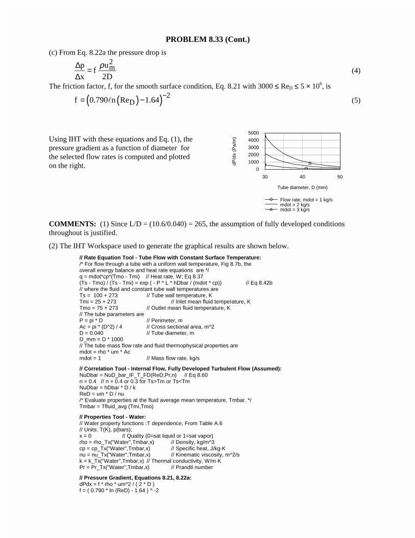
PROBLEM 8.33 (Cont.)
(c) From Eq. 8.22a the pressure drop is2mp u
fx 2D
ρ∆ =∆
(4)
The friction factor, f, for the smooth surface condition, Eq. 8.21 with 3000 ≤ ReD ≤ 5 × 10⁶, is
( )( ) 2Df 0.790 n Re 1.64
−= −� (5)
Using IHT with these equations and Eq. (1), thepressure gradient as a function of diameter forthe selected flow rates is computed and plottedon the right.
30 40 50
Tube diameter, D (mm)
0
1000
2000
3000
4000
5000
dP/d
x (P
a/m
)
Flow rate, mdot = 1 kg/smdot = 2 kg/smdot = 3 kg/s
COMMENTS: (1) Since L/D = (10.6/0.040) = 265, the assumption of fully developed conditionsthroughout is justified.
(2) The IHT Workspace used to generate the graphical results are shown below.
// Rate Equation Tool - Tube Flow with Constant Surface Temperature:/* For flow through a tube with a uniform wall temperature, Fig 8.7b, theoverall energy balance and heat rate equations are */q = mdot*cp*(Tmo - Tmi) // Heat rate, W; Eq 8.37(Ts - Tmo) / (Ts - Tmi) = exp ( - P * L * hDbar / (mdot * cp)) // Eq 8.42b// where the fluid and constant tube wall temperatures areTs = 100 + 273 // Tube wall temperature, KTmi = 25 + 273 // Inlet mean fluid temperature, KTmo = 75 + 273 // Outlet mean fluid temperature, K// The tube parameters areP = pi * D // Perimeter, mAc = pi * (D^2) / 4 // Cross sectional area, m^2D = 0.040 // Tube diameter, mD_mm = D * 1000// The tube mass flow rate and fluid thermophysical properties aremdot = rho * um * Acmdot = 1 // Mass flow rate, kg/s
// Correlation Tool - Internal Flow, Fully Developed Turbulent Flow (Assumed):NuDbar = NuD_bar_IF_T_FD(ReD,Pr,n) // Eq 8.60n = 0.4 // n = 0.4 or 0.3 for Ts>Tm or Ts<TmNuDbar = hDbar * D / kReD = um * D / nu/* Evaluate properties at the fluid average mean temperature, Tmbar. */Tmbar = Tfluid_avg (Tmi,Tmo)
// Properties Tool - Water:// Water property functions :T dependence, From Table A.6// Units: T(K), p(bars);x = 0 // Quality (0=sat liquid or 1=sat vapor)rho = rho_Tx("Water",Tmbar,x) // Density, kg/m^3cp = cp_Tx("Water",Tmbar,x) // Specific heat, J/kg·Knu = nu_Tx("Water",Tmbar,x) // Kinematic viscosity, m^2/sk = k_Tx("Water",Tmbar,x) // Thermal conductivity, W/m·KPr = Pr_Tx("Water",Tmbar,x) // Prandtl number
// Pressure Gradient, Equations 8.21, 8.22a:dPdx = f * rho * um^2 / ( 2 * D )f = ( 0.790 * ln (ReD) - 1.64 ) ^ -2
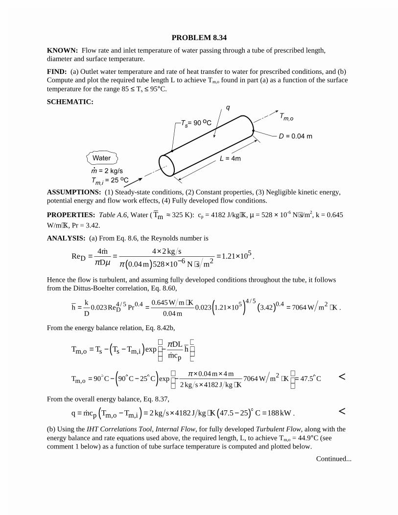
PROBLEM 8.34
KNOWN: Flow rate and inlet temperature of water passing through a tube of prescribed length,diameter and surface temperature.
FIND: (a) Outlet water temperature and rate of heat transfer to water for prescribed conditions, and (b)Compute and plot the required tube length L to achieve Tm,o found in part (a) as a function of the surfacetemperature for the range 85 ≤ Ts ≤ 95°C.
SCHEMATIC:
ASSUMPTIONS: (1) Steady-state conditions, (2) Constant properties, (3) Negligible kinetic energy,potential energy and flow work effects, (4) Fully developed flow conditions.
PROPERTIES: Table A.6, Water ( mT ≈ 325 K): cp = 4182 J/kg⋅K, µ = 528 × 10-6 N⋅s/m2, k = 0.645
W/m⋅K, Pr = 3.42.
ANALYSIS: (a) From Eq. 8.6, the Reynolds number is
( )5
D 6 24m 4 2 kg s
Re 1.21 10D 0.04m 528 10 N s mπ µ π −
×= = = ×× ⋅
�.
Hence the flow is turbulent, and assuming fully developed conditions throughout the tube, it followsfrom the Dittus-Boelter correlation, Eq. 8.60,
( ) ( )4 / 5 0.44 / 5 0.4 5 2
Dk 0.645 W m K
h 0.023Re Pr 0.023 1.21 10 3.42 7064 W m KD 0.04 m
⋅= = × = ⋅ .
From the energy balance relation, Eq. 8.42b,
( )m,o s s m,ip
DLT T T T exp h
mc
π = − − − �
( ) 2m,o
0.04 m 4 mT 90 C 90 C 25 C exp 7064 W m K 47.5 C
2 kg s 4182 J kg K
π× ×= − − − ⋅ =
× ⋅
$ $ $ $ <
From the overall energy balance, Eq. 8.37,
( ) ( )p m,o m,iq mc T T 2 kg s 4182 J kg K 47.5 25 C 188kW= − = × ⋅ − =$
� . <(b) Using the IHT Correlations Tool, Internal Flow, for fully developed Turbulent Flow, along with theenergy balance and rate equations used above, the required length, L, to achieve Tm,o = 44.9°C (seecomment 1 below) as a function of tube surface temperature is computed and plotted below.
Continued...
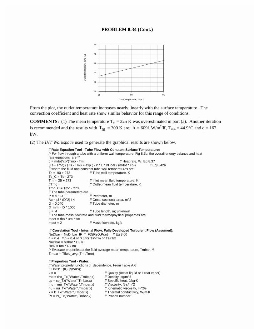
PROBLEM 8.34 (Cont.)
85 90 95
Tube temperature, Ts (C)
40
42
44
46
48
50
Out
let t
empe
ratu
re, T
mo
(C)
From the plot, the outlet temperature increases nearly linearly with the surface temperature. Theconvection coefficient and heat rate show similar behavior for this range of conditions.
COMMENTS: (1) The mean temperature Tm = 325 K was overestimated in part (a). Another iteration
is recommended and the results with mT = 309 K are: h = 6091 W/m2⋅K, Tm,o = 44.9°C and q = 167kW.
(2) The IHT Workspace used to generate the graphical results are shown below.
// Rate Equation Tool - Tube Flow with Constant Surface Temperature:/* For flow through a tube with a uniform wall temperature, Fig 8.7b, the overall energy balance and heatrate equations are */q = mdot*cp*(Tmo - Tmi) // Heat rate, W; Eq 8.37(Ts - Tmo) / (Ts - Tmi) = exp ( - P * L * hDbar / (mdot * cp)) // Eq 8.42b// where the fluid and constant tube wall temperatures areTs = 90 + 273 // Tube wall temperature, KTs_C = Ts - 273Tmi = 25 + 273 // Inlet mean fluid temperature, K//Tmo = // Outlet mean fluid temperature, KTmo_C = Tmo - 273// The tube parameters areP = pi * D // Perimeter, mAc = pi * (D^2) / 4 // Cross sectional area, m^2D = 0.040 // Tube diameter, mD_mm = D * 1000L = 4 // Tube length, m; unknown// The tube mass flow rate and fluid thermophysical properties aremdot = rho * um * Acmdot = 2 // Mass flow rate, kg/s
// Correlation Tool - Internal Flow, Fully Developed Turbulent Flow (Assumed):NuDbar = NuD_bar_IF_T_FD(ReD,Pr,n) // Eq 8.60n = 0.4 // n = 0.4 or 0.3 for Ts>Tm or Ts<TmNuDbar = hDbar * D / kReD = um * D / nu/* Evaluate properties at the fluid average mean temperature, Tmbar. */Tmbar = Tfluid_avg (Tmi,Tmo)
// Properties Tool - Water:// Water property functions :T dependence, From Table A.6// Units: T(K), p(bars);x = 0 // Quality (0=sat liquid or 1=sat vapor)rho = rho_Tx("Water",Tmbar,x) // Density, kg/m^3cp = cp_Tx("Water",Tmbar,x) // Specific heat, J/kg·Kmu = mu_Tx("Water",Tmbar,x) // Viscosity, N·s/m^2nu = nu_Tx("Water",Tmbar,x) // Kinematic viscosity, m^2/sk = k_Tx("Water",Tmbar,x) // Thermal conductivity, W/m·KPr = Pr_Tx("Water",Tmbar,x) // Prandtl number
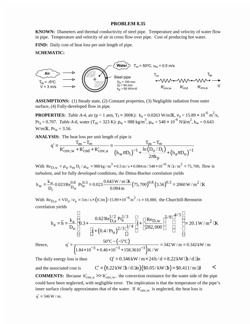
PROBLEM 8.35
KNOWN: Diameters and thermal conductivity of steel pipe. Temperature and velocity of water flowin pipe. Temperature and velocity of air in cross flow over pipe. Cost of producing hot water.
FIND: Daily cost of heat loss per unit length of pipe.
SCHEMATIC:
ASSUMPTIONS: (1) Steady state, (2) Constant properties, (3) Negligible radiation from outersurface, (4) Fully-developed flow in pipe.
PROPERTIES: Table A-4, air (p = 1 atm, Tf ≈ 300K): ka = 0.0263 W/m⋅K, νa = 15.89 × 10⁻⁶
m2/s,
Pra = 0.707. Table A-6, water (Tm = 323 K): ρw = 988 kg/m3, µw = 548 × 10
-6 N⋅s/m
2, kw = 0.643
W/m⋅K, Prw = 3.56.
ANALYSIS: The heat loss per unit length of pipe is
( ) ( ) ( )m m
1 1o icnv,w cnd cnv,aw i a o
p
T T T Tq
ln D / DR R Rh D h D
2 kπ π
π
∞ ∞− −
− −′ = =′ ′ ′+ +
+ +
With 3 6 2D,w w m i wRe u D / 988 kg / m 0.5 m / s 0.084 m / 548 10 N s / m 75, 700,ρ µ −= = × × × ⋅ = flow is
turbulent, and for fully developed conditions, the Dittus-Boelter correlation yields
( ) ( )w
0.8 0.30.8 0.3 2ww wD
i
k 0.643 W / m Kh 0.023Re Pr 0.023 75, 700 3.56 2060 W / m K
D 0.084 m
⋅= = = ⋅
With ( ) 6 2D,a o aRe VD / 3 m / s 0.1m /15.89 10 m / s 18,880,ν −= = × × = the Churchill-Bernstein
correlation yields
( )
4 /51/ 2 1/3 5/8aD,a D,w 2a
a 1/ 4o 2 /3a
0.62 Re Pr Rekh h 0.3 1 20.1W / m K
D 282,0001 0.4 / Pr
= = + + = ⋅ +
Hence,( )
( )3 3 3
50 C 5 Cq 342 W / m 0.342 kW / m
1.84 10 0.46 10 158.3610 K / W− − −° − − °′ = = =
× + × +
The daily energy loss is then Q 0.346kW / m 24h / d 8.22 kW h / d m′ = × = ⋅ ⋅
and the associated cost is ( )( )C 8.22 kW h / d m $0.05 / kW h $0.411/ m d′ = ⋅ ⋅ ⋅ = ⋅ <COMMENTS: Because cnv,a cnv,wR R ,′ ′>> the convection resistance for the water side of the pipe
could have been neglected, with negligible error. The implication is that the temperature of the pipe’sinner surface closely approximates that of the water. If cnv,wR ′ is neglected, the heat loss is
q 346 W / m.′ =
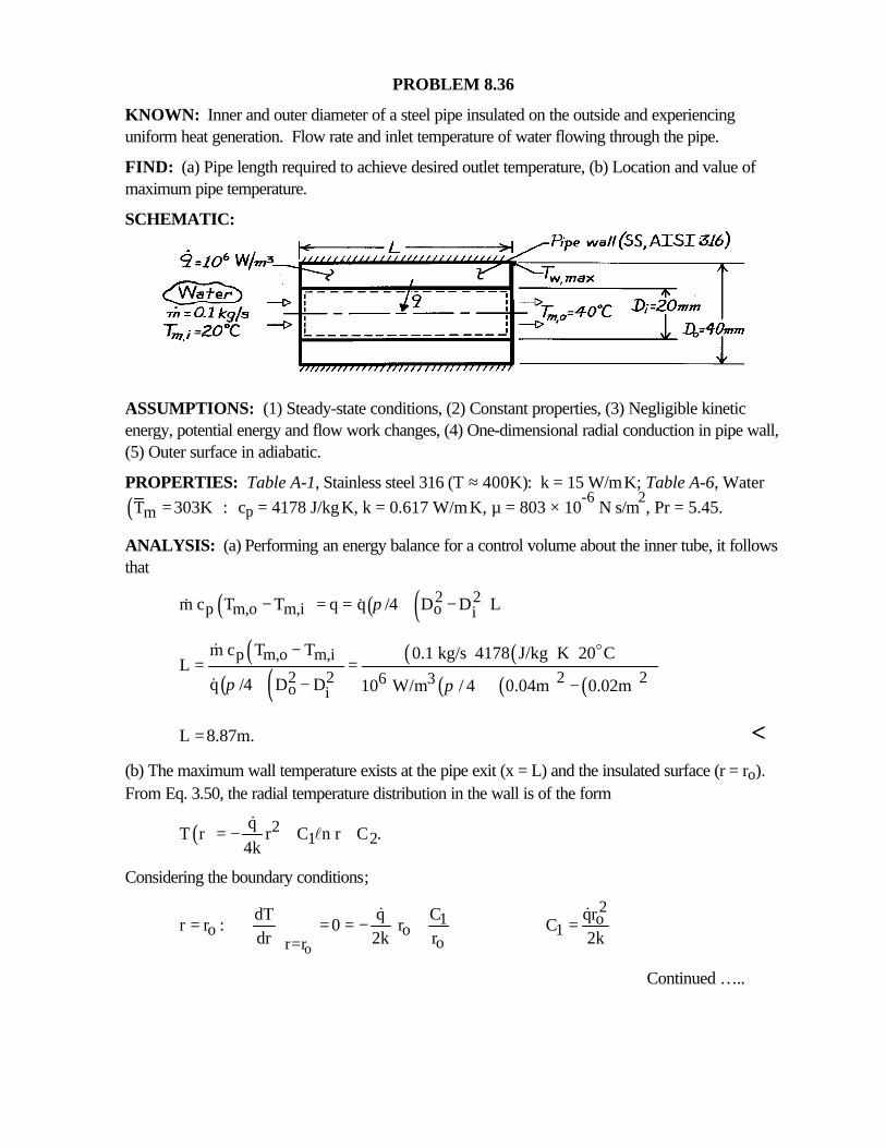
PROBLEM 8.36
KNOWN: Inner and outer diameter of a steel pipe insulated on the outside and experiencinguniform heat generation. Flow rate and inlet temperature of water flowing through the pipe.
FIND: (a) Pipe length required to achieve desired outlet temperature, (b) Location and value ofmaximum pipe temperature.
SCHEMATIC:
ASSUMPTIONS: (1) Steady-state conditions, (2) Constant properties, (3) Negligible kineticenergy, potential energy and flow work changes, (4) One-dimensional radial conduction in pipe wall,(5) Outer surface in adiabatic.
PROPERTIES: Table A-1, Stainless steel 316 (T ≈ 400K): k = 15 W/m⋅K; Table A-6, Water
( )mT 303K := cp = 4178 J/kg⋅K, k = 0.617 W/m⋅K, µ = 803 × 10-6
N⋅s/m2, Pr = 5.45.
ANALYSIS: (a) Performing an energy balance for a control volume about the inner tube, it followsthat
( ) ( ) ( )2 2p m,o m,i o im c T T q q /4 D D Lπ− = = −& &
( )( ) ( )
( ) ( )( ) ( ) ( )
p m,o m,i2 2 2 26 3o i
m c T T 0.1 kg/s 4178 J/kg K 20 CL
q /4 D D 10 W/m / 4 0.04m 0.02mπ π
− ⋅= =
− −
o&
&
L 8.87m.= <(b) The maximum wall temperature exists at the pipe exit (x = L) and the insulated surface (r = ro).From Eq. 3.50, the radial temperature distribution in the wall is of the form
( ) 21 2
qT r r C n r C .
4k= − + +
&l
Considering the boundary conditions;
o
2o1
o o 1or r
qrdT q Cr r : 0 r C
dr 2k r 2k=
= = = − + =&&
Continued …..
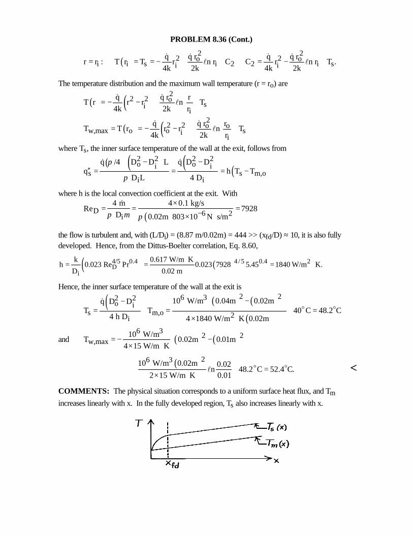
PROBLEM 8.36 (Cont.)
( )2 2
2 2o oi i s i 2 2 i si i
q r q rq qr r : T r T r n r C C r n r T .
4k 2k 4k 2k= = = − + + = − +
& && &l l
The temperature distribution and the maximum wall temperature (r = ro) are
( ) ( ) 22 2 o
sii
q rq rT r r r n T
4k 2k r= − − + +
&&l
( ) ( ) 22 2 o o
w,max o o sii
q r rqT T r r r n T
4k 2k r= = − − + +
&&l
where Ts, the inner surface temperature of the wall at the exit, follows from
( ) ( ) ( ) ( )2 2 2 2o oi i
s s m,oi i
q /4 D D L q D Dq h T T
D L 4 D
π
π
− −′′ = = = −
& &
where h is the local convection coefficient at the exit. With
( )D 6 2i
4 m 4 0.1 kg/sRe 7928
D 0.02m 803 10 N s/mπ µ π −×
= = =× ⋅
&
the flow is turbulent and, with (L/Di) = (8.87 m/0.02m) = 444 >> (xfd/D) ≈ 10, it is also fullydeveloped. Hence, from the Dittus-Boelter correlation, Eq. 8.60,
( ) ( )4 / 54/5 0.4 0.4 2D
i
k 0.617 W/m Kh 0.023 Re Pr 0.023 7928 5.45 1840 W/m K.
D 0.02 m
⋅= = = ⋅
Hence, the inner surface temperature of the wall at the exit is
( ) ( ) ( )
( )
2 26 32 2o i
s m,o 2i
10 W/m 0.04m 0.02mq D DT T 40 C 48.2 C
4 h D 4 1840 W/m K 0.02m
−− = + = + =× ⋅
o o&
and ( ) ( )6 3
2 2w,max
10 W/mT 0.02m 0.01m
4 15 W/m K = − − × ⋅
( )26 310 W/m 0.02m 0.02n 48.2 C 52.4 C.
2 15 W/m K 0.01+ + =
× ⋅o ol <
COMMENTS: The physical situation corresponds to a uniform surface heat flux, and Tm
increases linearly with x. In the fully developed region, Ts also increases linearly with x.
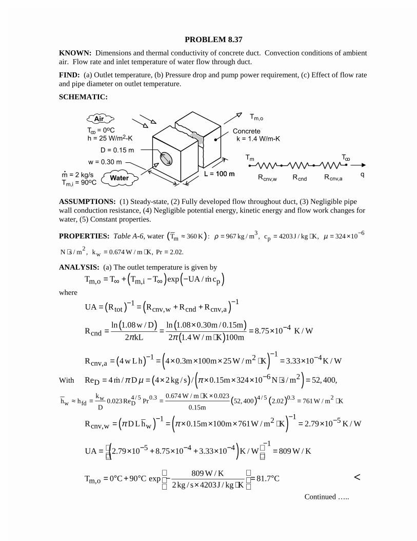
PROBLEM 8.37
KNOWN: Dimensions and thermal conductivity of concrete duct. Convection conditions of ambientair. Flow rate and inlet temperature of water flow through duct.
FIND: (a) Outlet temperature, (b) Pressure drop and pump power requirement, (c) Effect of flow rateand pipe diameter on outlet temperature.
SCHEMATIC:
ASSUMPTIONS: (1) Steady-state, (2) Fully developed flow throughout duct, (3) Negligible pipewall conduction resistance, (4) Negligible potential energy, kinetic energy and flow work changes forwater, (5) Constant properties.
PROPERTIES: Table A-6, water ( )mT 360 K :≈ 3967 kg / m ,ρ = pc 4203 J / kg K,= ⋅ 6324 10µ −= ×
2N s / m ,⋅ wk 0.674 W / m K, Pr 2.02.= ⋅ =
ANALYSIS: (a) The outlet temperature is given by
( ) ( )m,o m,i pT T T T exp UA / m c∞ ∞= + − − �
where
( ) ( ) 11tot cnv,w cnd cnv,aUA R R R R
−−= = + +
( ) ( )( )
4cnd
ln 1.08w / D ln 1.08 0.30m / 0.15mR 8.75 10 K / W
2 kL 2 1.4 W / m K 100mπ π−×
= = = ×⋅
( ) ( ) 11 2 4cnv,aR 4 w L h 4 0.3m 100m 25W / m K 3.33 10 K / W
−− −= = × × × ⋅ = ×
With ( ) ( )6 2DRe 4 m / D 4 2 kg / s / 0.15m 324 10 N s / m 52, 400,π µ π −= = × × × × ⋅ =�
( ) ( )4 / 5 0.3 24 / 5 0.3ww fd D
k 0.674 W / m K 0.023h h 0.023 Re Pr 52, 400 2.02 761W / m K
D 0.15m
⋅ ×≈ = = = ⋅
( ) ( ) 11 2 5cnv,w wR D L h 0.15m 100m 761W / m K 2.79 10 K / Wπ π
−− −= = × × × ⋅ = ×
( ) 15 4 4UA 2.79 10 8.75 10 3.33 10 K / W 809 W / K
−− − − = × + × + × =
m,o809 W / K
T 0 C 90 C exp 81.7 C2kg / s 4203J / kg K
= ° + ° − = ° × ⋅
<
Continued …..
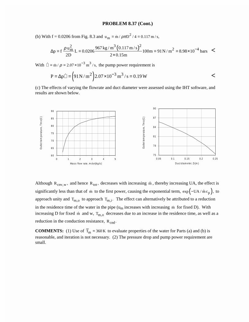
PROBLEM 8.37 (Cont.)
(b) With f = 0.0206 from Fig. 8.3 and 2mu m / D / 4 0.117 m / s,ρπ= =�
( )2322 4m 967 kg / m 0.117 m / su
p f L 0.0206 100m 91N / m 8.98 10 bars2D 2 0.15m
ρ −∆ = = = = ××
<
With 3 3m / 2.07 10 m / s,ρ −∀ = = ×�
� the pump power requirement is
( )2 3 3P p 91N / m 2.07 10 m / s 0.19 W−= ∆ ∀ = × =� <
(c) The effects of varying the flowrate and duct diameter were assessed using the IHT software, andresults are shown below.
Although cnv,wR , and hence totR , decreases with increasing m� , thereby increasing UA, the effect is
significantly less than that of m� to the first power, causing the exponential term, ( )pexp UA / m c ,− � to
approach unity and m,oT to approach m,iT . The effect can alternatively be attributed to a reduction
in the residence time of the water in the pipe (um increases with increasing m� for fixed D). Withincreasing D for fixed m� and w, m,oT decreases due to an increase in the residence time, as well as a
reduction in the conduction resistance, cndR .
COMMENTS: (1) Use of mT 360 K= to evaluate properties of the water for Parts (a) and (b) isreasonable, and iteration is not necessary. (2) The pressure drop and pump power requirement aresmall.
0 1 2 3 4 5
Ma s s flow ra te , m d o t(kg /s )
6 0
6 5
7 0
7 5
8 0
8 5
9 0
Ou
tlet t
em
pe
ratu
re, T
mo
(C)
0 .0 5 0 .1 0 .1 5 0 .2 0 .2 5
D u ct d ia m e te r, D (m )
7 5
7 8
8 1
8 4
8 7
9 0
Out
let t
empe
ratu
re, T
mo(
C)
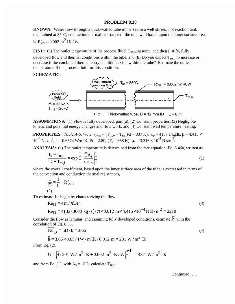
PROBLEM 8.38
KNOWN: Water flow through a thick-walled tube immersed in a well stirred, hot reaction tankmaintained at 85°C; conduction thermal resistance of the tube wall based upon the inner surface area
is 2cdR 0.002 m K / W.′′ = ⋅
FIND: (a) The outlet temperature of the process fluid, Tm,o; assume, and then justify, fully
developed flow and thermal conditions within the tube; and (b) Do you expect Tm,o to increase ordecrease if the combined thermal entry condition exists within the tube? Estimate the outlettemperature of the process fluid for this condition.
SCHEMATIC:
ASSUMPTIONS: (1) Flow is fully developed, part (a), (2) Constant properties, (3) Negligiblekinetic and potential energy changes and flow work, and (4) Constant wall temperature heating.
PROPERTIES: Table A-6, Water (Tm = (Tm,o + Tm,i)/2 = 337 K): cp = 4187 J/kg⋅K, µ = 4.415 ×10
-4 N⋅s/m
2, k = 0.6574 W/m⋅K, Pr = 2.80; (Ts = 358 K): µs = 3.316 × 10
-4 N⋅s/m
2.
ANALYSIS: (a) The outlet temperature is determined from the rate equation, Eq. 8.46a, written as
s m,o s
s m,i p
T T UAexp
T T m c
−= − − �
(1)
where the overall coefficient, based upon the inner surface area of the tube is expressed in terms ofthe convection and conduction thermal resistances,
cd,i1 1
RU h
′′= +
(2)
To estimate h, begin by characterizing the flow
DRe 4 m / Dπ µ= � (3)
( ) 4 2DRe 4 33/ 3600 kg / s / 0.012 m 4.415 10 N s / m 2210π −= × × × ⋅ =
Consider the flow as laminar, and assuming fully developed conditions, estimate h with thecorrelation of Eq. 8.55,
DNu hD / k 3.66= = (4)
2h 3.66 0.6574 W / m K / 0.012 m 201 W / m K= × ⋅ = ⋅From Eq. (2),
12 2 2U 1/ 201 W / m K 0.002 m K / W 143.1 W / m K− = ⋅ + ⋅ = ⋅
and from Eq. (1), with As = πDL, calculate Tm,o.
Continued …..
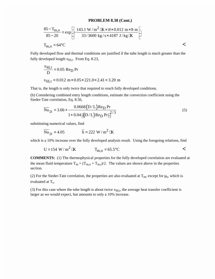
PROBLEM 8.38 (Cont.)
2m,o85 T 143.1 W / m K 0.012 m 8 m
exp85 20 33/ 3600 kg / s 4187 J / kg K
π − ⋅ × × × = − − × ⋅
m,oT 64 C= ° <Fully developed flow and thermal conditions are justified if the tube length is much greater than the
fully developed length xfd,t. From Eq. 8.23,
fd,tD
x0.05 Re Pr
D=
fd,tx 0.012 m 0.05 221.0 2.41 3.20 m= × × × =
That is, the length is only twice that required to reach fully developed conditions.
(b) Considering combined entry length conditions, estimate the convection coefficient using theSieder-Tate correlation, Eq. 8.56,
( )( )
DD
2/3D
0.0668 D / L Re PrNu 3.66
1 0.04 D / L Re Pr= +
+ (5)
substituting numerical values, find
D2Nu 4.05 h 222 W / m K= = ⋅
which is a 10% increase over the fully developed analysis result. Using the foregoing relations, find
2m,oU 154 W / m K T 65.5 C= ⋅ = ° <
COMMENTS: (1) The thermophysical properties for the fully developed correlation are evaluated at
the mean fluid temperature Tm = (Tm,o + Tm,i)/2. The values are shown above in the propertiessection.
(2) For the Sieder-Tate correlation, the properties are also evaluated at Tm, except for µs, which is
evaluated at Ts.
(3) For this case where the tube length is about twice xfd,t, the average heat transfer coefficient islarger as we would expect, but amounts to only a 10% increase.
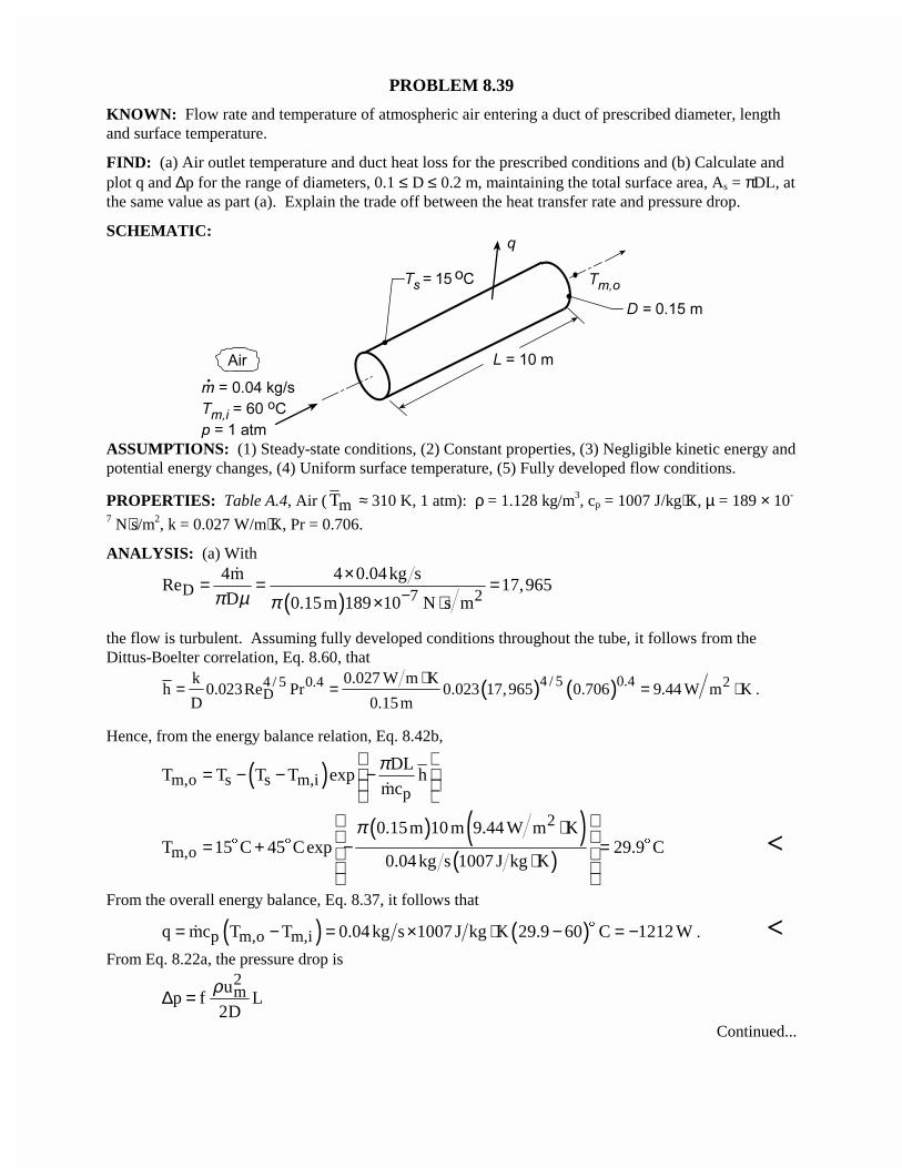
PROBLEM 8.39
KNOWN: Flow rate and temperature of atmospheric air entering a duct of prescribed diameter, lengthand surface temperature.
FIND: (a) Air outlet temperature and duct heat loss for the prescribed conditions and (b) Calculate andplot q and ∆p for the range of diameters, 0.1 ≤ D ≤ 0.2 m, maintaining the total surface area, As = πDL, atthe same value as part (a). Explain the trade off between the heat transfer rate and pressure drop.
SCHEMATIC:
ASSUMPTIONS: (1) Steady-state conditions, (2) Constant properties, (3) Negligible kinetic energy andpotential energy changes, (4) Uniform surface temperature, (5) Fully developed flow conditions.
PROPERTIES: Table A.4, Air ( mT ≈ 310 K, 1 atm): ρ = 1.128 kg/m3, cp = 1007 J/kg⋅K, µ = 189 × 10-
7 N⋅s/m2, k = 0.027 W/m⋅K, Pr = 0.706.
ANALYSIS: (a) With
( )D 7 24m 4 0.04kg s
Re 17,965D 0.15m 189 10 N s mπ µ π −
×= = =× ⋅
�
the flow is turbulent. Assuming fully developed conditions throughout the tube, it follows from theDittus-Boelter correlation, Eq. 8.60, that
( ) ( )4 / 5 0.44 / 5 0.4 2D
k 0.027 W m Kh 0.023Re Pr 0.023 17,965 0.706 9.44 W m K
D 0.15m
⋅= = = ⋅ .
Hence, from the energy balance relation, Eq. 8.42b,
( )m,o s s m,ip
DLT T T T exp h
mc
π = − − − �
( ) ( )( )
2
m,o
0.15m 10 m 9.44 W m KT 15 C 45 Cexp 29.9 C
0.04 kg s 1007 J kg K
π ⋅ = + − = ⋅
$ $ $ <
From the overall energy balance, Eq. 8.37, it follows that
( ) ( )p m,o m,iq mc T T 0.04 kg s 1007 J kg K 29.9 60 C 1212 W= − = × ⋅ − = −$� . <
From Eq. 8.22a, the pressure drop is2mu
p f L2D
ρ∆ =
Continued...
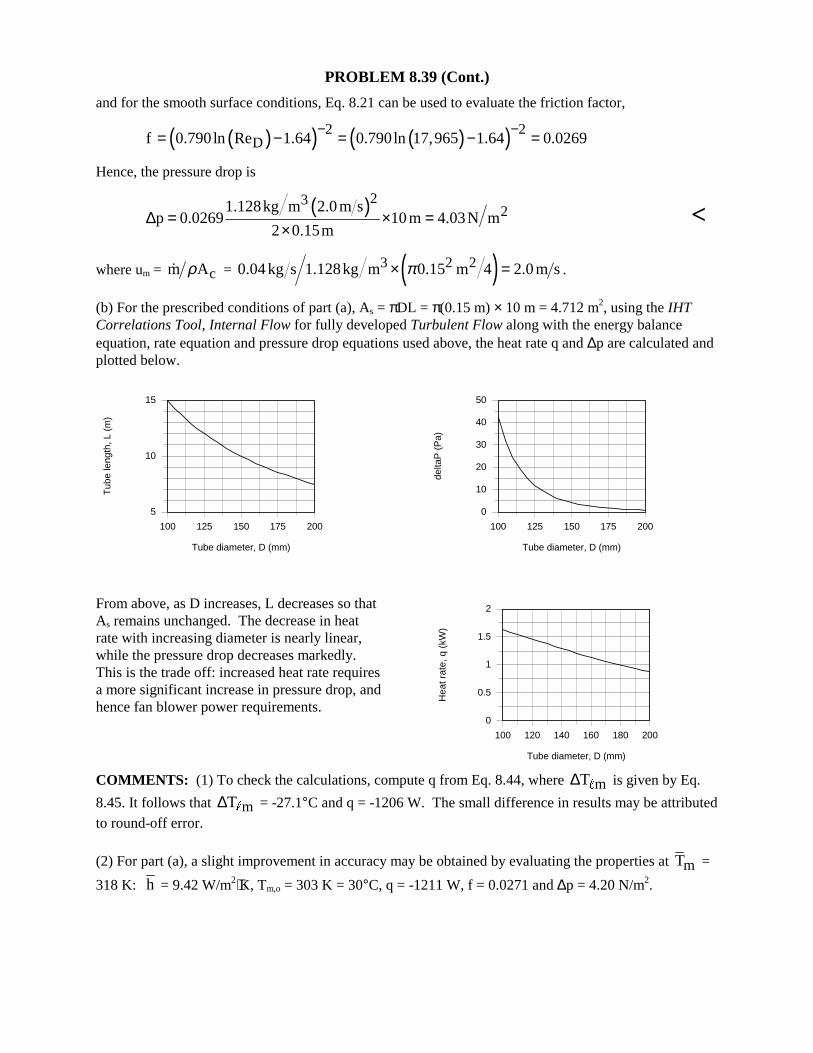
PROBLEM 8.39 (Cont.)
and for the smooth surface conditions, Eq. 8.21 can be used to evaluate the friction factor,
( )( ) ( )( )2 2Df 0.790ln Re 1.64 0.790ln 17,965 1.64 0.0269
− −= − = − =
Hence, the pressure drop is
( )2321.128kg m 2.0 m s
p 0.0269 10 m 4.03N m2 0.15m
∆ = × =×
<
where um = cm Aρ� = ( )3 2 20.04 kg s 1.128kg m 0.15 m 4 2.0 m sπ× = .
(b) For the prescribed conditions of part (a), As = πDL = π(0.15 m) × 10 m = 4.712 m2, using the IHTCorrelations Tool, Internal Flow for fully developed Turbulent Flow along with the energy balanceequation, rate equation and pressure drop equations used above, the heat rate q and ∆p are calculated andplotted below.
100 125 150 175 200
Tube diameter, D (mm)
5
10
15
Tub
e le
ngth
, L (
m)
100 125 150 175 200
Tube diameter, D (mm)
0
10
20
30
40
50
delta
P (
Pa)
From above, as D increases, L decreases so thatAs remains unchanged. The decrease in heatrate with increasing diameter is nearly linear,while the pressure drop decreases markedly.This is the trade off: increased heat rate requiresa more significant increase in pressure drop, andhence fan blower power requirements.
100 120 140 160 180 200
Tube diameter, D (mm)
0
0.5
1
1.5
2
Hea
t rat
e, q
(kW
)
COMMENTS: (1) To check the calculations, compute q from Eq. 8.44, where mT∆ " is given by Eq.
8.45. It follows that mT∆ " = -27.1°C and q = -1206 W. The small difference in results may be attributedto round-off error.
(2) For part (a), a slight improvement in accuracy may be obtained by evaluating the properties at mT =
318 K: h = 9.42 W/m2⋅K, Tm,o = 303 K = 30°C, q = -1211 W, f = 0.0271 and ∆p = 4.20 N/m2.
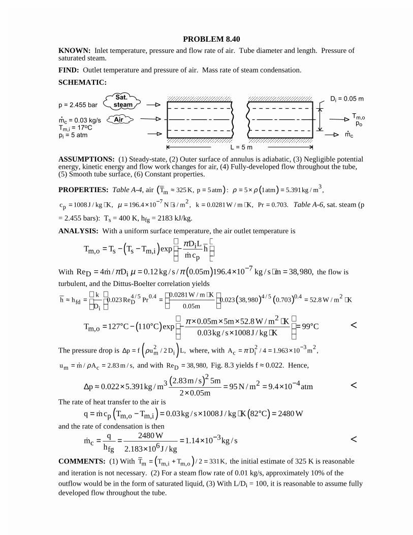
PROBLEM 8.40KNOWN: Inlet temperature, pressure and flow rate of air. Tube diameter and length. Pressure ofsaturated steam.
FIND: Outlet temperature and pressure of air. Mass rate of steam condensation.
SCHEMATIC:
ASSUMPTIONS: (1) Steady-state, (2) Outer surface of annulus is adiabatic, (3) Negligible potentialenergy, kinetic energy and flow work changes for air, (4) Fully-developed flow throughout the tube,(5) Smooth tube surface, (6) Constant properties.
PROPERTIES: Table A-4, air ( )mT 325 K, p 5 atm :≈ = ( ) 35 1atm 5.391kg / m ,ρ ρ= × =
pc 1008 J / kg K,= ⋅ 7 2196.4 10 N s / m ,µ −= × ⋅ k 0.0281W / m K,= ⋅ Pr 0.703.= Table A-6, sat. steam (p
= 2.455 bars): Ts = 400 K, hfg = 2183 kJ/kg.
ANALYSIS: With a uniform surface temperature, the air outlet temperature is
( ) im,o s s m,i
p
D LT T T T exp h
m c
π = − − − �
With ( ) 7D iRe 4m / D 0.12 kg / s / 0.05m 196.4 10 kg / s m 38,980,π µ π −= = × ⋅ =� the flow is
turbulent, and the Dittus-Boelter correlation yields
( ) ( )4 / 5 0.4 24 / 5 0.4fd D
i
k 0.0281W / m Kh h 0.023 Re Pr 0.023 38,980 0.703 52.8 W / m K
D 0.05m
⋅≈ = = = ⋅
( )2
m,o0.05m 5m 52.8 W / m K
T 127 C 110 C exp 99 C0.03kg / s 1008J / kg K
π × × × ⋅ = ° − ° − = ° × ⋅
<
The pressure drop is ( )2m ip f u / 2 D L,ρ∆ = where, with 2 3 2
c iA D / 4 1.963 10 m ,π −= = ×
m cu m / A 2.83 m / s,ρ= =� and with DRe 38, 980,= Fig. 8.3 yields f ≈ 0.022. Hence,
( )23 2 42.83m / s 5mp 0.022 5.391kg / m 95 N / m 9.4 10 atm
2 0.05m−∆ ≈ × = = ×
×<
The rate of heat transfer to the air is
( ) ( )p m,o m,iq m c T T 0.03kg / s 1008J / kg K 82 C 2480 W= − = × ⋅ ° =�
and the rate of condensation is then
3c 6fg
q 2480 Wm 1.14 10 kg / s
h 2.183 10 J / kg
−= = = ××
� <
COMMENTS: (1) With ( )m m,i m,oT T T / 2 331K,= + = the initial estimate of 325 K is reasonable
and iteration is not necessary. (2) For a steam flow rate of 0.01 kg/s, approximately 10% of the
outflow would be in the form of saturated liquid, (3) With L/Di = 100, it is reasonable to assume fullydeveloped flow throughout the tube.
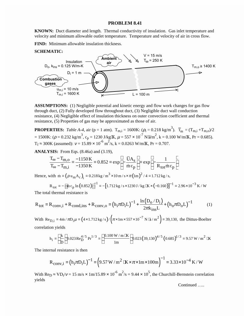
PROBLEM 8.41
KNOWN: Duct diameter and length. Thermal conductivity of insulation. Gas inlet temperature andvelocity and minimum allowable outlet temperature. Temperature and velocity of air in cross flow.
FIND: Minimum allowable insulation thickness.
SCHEMATIC:
ASSUMPTIONS: (1) Negligible potential and kinetic energy and flow work changes for gas flowthrough duct, (2) Fully developed flow throughout duct, (3) Negligible duct wall conductionresistance, (4) Negligible effect of insulation thickness on outer convection coefficient and thermalresistance, (5) Properties of gas may be approximated as those of air.
PROPERTIES: Table A-4, air (p = 1 atm). Tm,i = 1600K: (ρi = 0.218 kg/m3). mT = (Tm,i +Tm,o)/2
= 1500K: (ρ = 0.232 kg/m3, cp = 1230 J/kg⋅K, µ = 557 × 10
-7 N⋅s/m
2, k = 0.100 W/m⋅K, Pr = 0.685).
Tf ≈ 300K (assumed): ν = 15.89 × 10⁻⁶
m2/s, k = 0.0263 W/m⋅K, Pr = 0.707.
ANALYSIS: From Eqs. (8.46a) and (3.19),
m,o s
m,i p tot p
T T UA1150 K 10.852 exp exp
T T 1350 K m c R mc∞
∞
− −= = = − = − − − � �
Hence, with ( ) ( )3 2m c im u A 0.218 kg / m 10 m / s 1m / 4 1.712 kg / s,ρ π= = × × =�
( ) ( )[ ]1 1 3tot pR m c ln 0.852 1.712 kg / s 1230 J / kg K 0.160 2.96 10 K / W
− − −= − = − × ⋅ × − = × �
The total thermal resistance is
( ) ( ) ( )1 1o itot conv,i cond,ins conv,o i i o o
ins
ln D / DR R R R h D L h D L
2 k Lπ π
π− −= + + = + + (1)
With ( ) ( )7 2D,i iRe 4m / D 4 1.712 kg / s / 1m 557 10 N s / m 39,130,π µ π −= = × × × × ⋅ =� the Dittus-Boelter
correlation yields
( ) ( )4 / 5 1/ 3 24 / 5 1/ 3i D
k 0.100 W / m Kh 0.023 Re Pr 0.023 39,130 0.685 9.57 W / m K
D 1m
⋅= = = ⋅
The internal resistance is then
( ) ( ) 11 2 4conv,i i iR h D L 9.57 W / m K 1m 100m 3.33 10 K / Wπ π
−− −= = ⋅ × × × = ×
With ReD ≈ VDi/ν = 15 m/s × 1m/15.89 × 10-6
m2/s = 9.44 × 10
5, the Churchill-Bernstein correlation
yieldsContinued …..
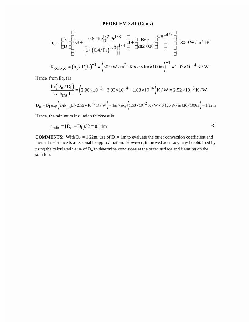
PROBLEM 8.41 (Cont.)
( )
4 /51/ 2 1/3 5/82DD
o 1/ 42 /3
0.62 Re Prk Reh 0.3 1 30.9 W / m K
D 282,0001 0.4 / Pr
≈ + + = ⋅ +
( ) ( ) 11 2 4conv,o o iR h D L 30.9 W / m K 1m 100m 1.03 10 K / Wπ π
−− −≈ = ⋅ × × × = ×
Hence, from Eq. (1)
( ) ( )o i 3 4 4 3
ins
ln D / D2.96 10 3.33 10 1.03 10 K / W 2.52 10 K / W
2 k Lπ− − − −= × − × − × = ×
( ) ( )3 2o i insD D exp 2 k L 2.52 10 K / W 1m exp 1.58 10 K / W 0.125 W / m K 100m 1.22mπ − −= × × = × × × ⋅ × =
Hence, the minimum insulation thickness is
( )min o it D D / 2 0.11m= − = <
COMMENTS: With Do = 1.22m, use of Di = 1m to evaluate the outer convection coefficient andthermal resistance is a reasonable approximation. However, improved accuracy may be obtained by
using the calculated value of Do to determine conditions at the outer surface and iterating on thesolution.
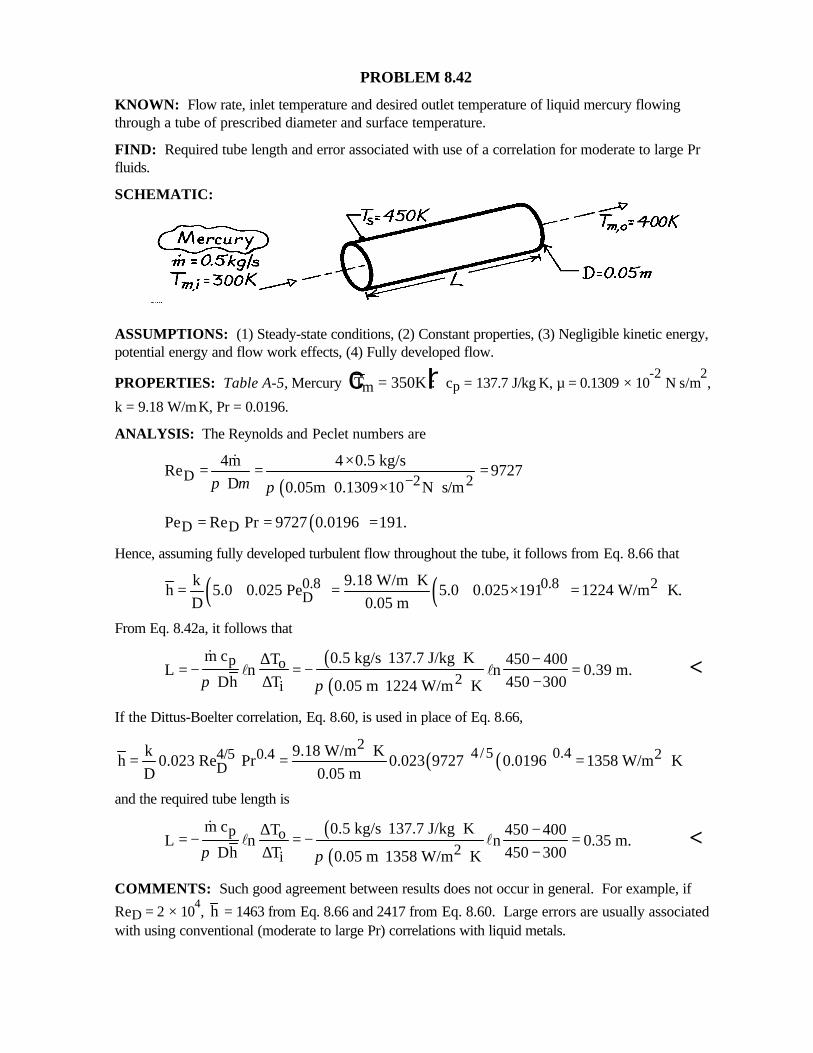
PROBLEM 8.42
KNOWN: Flow rate, inlet temperature and desired outlet temperature of liquid mercury flowingthrough a tube of prescribed diameter and surface temperature.
FIND: Required tube length and error associated with use of a correlation for moderate to large Prfluids.
SCHEMATIC:
ASSUMPTIONS: (1) Steady-state conditions, (2) Constant properties, (3) Negligible kinetic energy,potential energy and flow work effects, (4) Fully developed flow.
PROPERTIES: Table A-5, Mercury T Km = 350c h: cp = 137.7 J/kg⋅K, µ = 0.1309 × 10⁻²
N⋅s/m2,
k = 9.18 W/m⋅K, Pr = 0.0196.
ANALYSIS: The Reynolds and Peclet numbers are
( )D 2 24m 4 0.5 kg/s
Re 9727 D 0.05m 0.1309 10 N s/mπ µ π −
×= = =× ⋅
&
( )D DPe Re Pr 9727 0.0196 191.= = =
Hence, assuming fully developed turbulent flow throughout the tube, it follows from Eq. 8.66 that
( ) ( )0.8 0.8 2D
k 9.18 W/m Kh 5.0 0.025 Pe 5.0 0.025 191 1224 W/m K.
D 0.05 m⋅= + = + × = ⋅
From Eq. 8.42a, it follows that
( )( )
p o2i
m c 0.5 kg/s 137.7 J/kg KT 450 400L n n 0.39 m.
Dh T 450 3000.05 m 1224 W/m Kπ π
⋅∆ −= − = − =
∆ −⋅
&l l <
If the Dittus-Boelter correlation, Eq. 8.60, is used in place of Eq. 8.66,
( ) ( )2
4/5 0.44/5 0.4 2D
k 9.18 W/m Kh 0.023 Re Pr 0.023 9727 0.0196 1358 W/m K
D 0.05 m⋅= = = ⋅
and the required tube length is
( )( )
p o2i
m c 0.5 kg/s 137.7 J/kg KT 450 400L n n 0.35 m.
Dh T 450 3000.05 m 1358 W/m Kπ π
⋅∆ −= − = − =∆ −⋅
&l l <
COMMENTS: Such good agreement between results does not occur in general. For example, if
ReD = 2 × 10⁴, h = 1463 from Eq. 8.66 and 2417 from Eq. 8.60. Large errors are usually associated
with using conventional (moderate to large Pr) correlations with liquid metals.
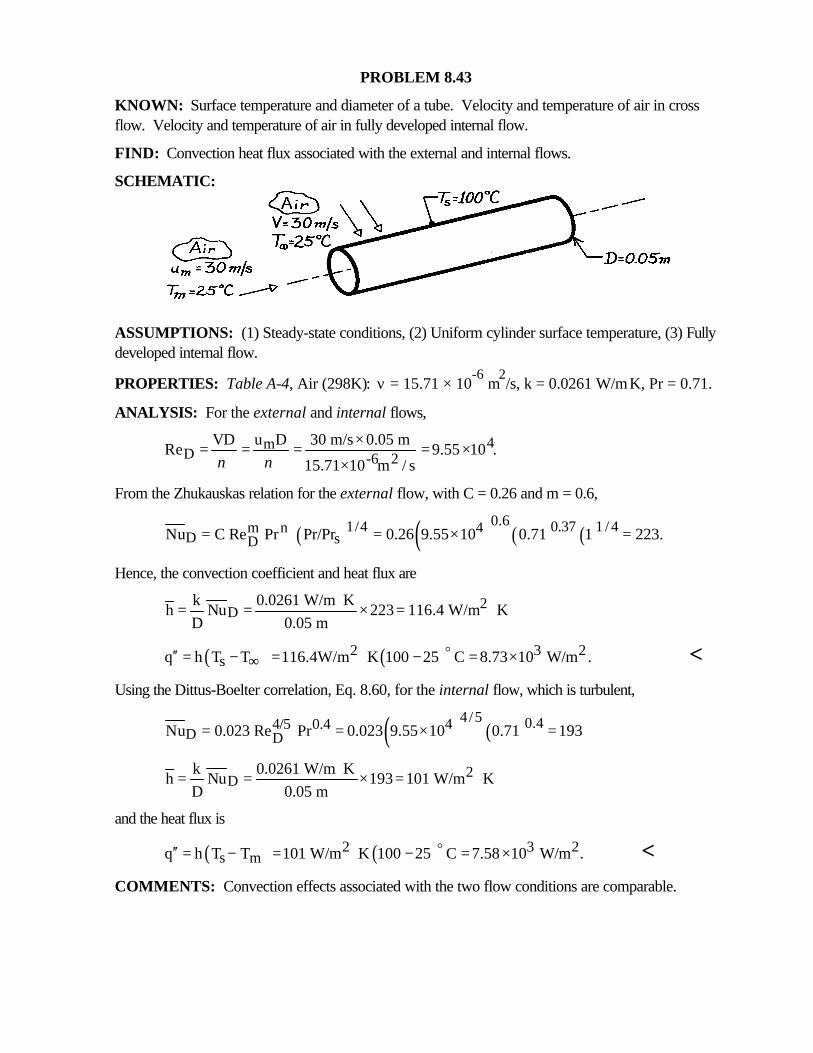
PROBLEM 8.43
KNOWN: Surface temperature and diameter of a tube. Velocity and temperature of air in crossflow. Velocity and temperature of air in fully developed internal flow.
FIND: Convection heat flux associated with the external and internal flows.
SCHEMATIC:
ASSUMPTIONS: (1) Steady-state conditions, (2) Uniform cylinder surface temperature, (3) Fullydeveloped internal flow.
PROPERTIES: Table A-4, Air (298K): ν = 15.71 × 10⁻⁶
m2/s, k = 0.0261 W/m⋅K, Pr = 0.71.
ANALYSIS: For the external and internal flows,
4mD -6 2
VD u D 30 m/s 0.05 mRe 9.55 10 .
15.71 10 m / sν ν×= = = = ×
×
From the Zhukauskas relation for the external flow, with C = 0.26 and m = 0.6,
( ) ( ) ( ) ( )0.61/4 0.37 1 / 4m n 4
D sDNu C Re Pr Pr/Pr 0.26 9.55 10 0.71 1 223.= = × =
Hence, the convection coefficient and heat flux are
2D
k 0.0261 W/m Kh Nu 223 116.4 W/m K
D 0.05 m⋅= = × = ⋅
( ) ( )2 3 2sq h T T 116.4W/m K 100 25 C 8.73 10 W/m .∞′′ = − = ⋅ − = ×o <
Using the Dittus-Boelter correlation, Eq. 8.60, for the internal flow, which is turbulent,
( ) ( )4/5 0.44/5 0.4 4
D DNu 0.023 Re Pr 0.023 9.55 10 0.71 193= = × =
2D
k 0.0261 W/m Kh Nu 193 101 W/m K
D 0.05 m⋅= = × = ⋅
and the heat flux is
( ) ( )2 3 2s mq h T T 101 W/m K 100 25 C 7.58 10 W/m .′′ = − = ⋅ − = ×o <
COMMENTS: Convection effects associated with the two flow conditions are comparable.
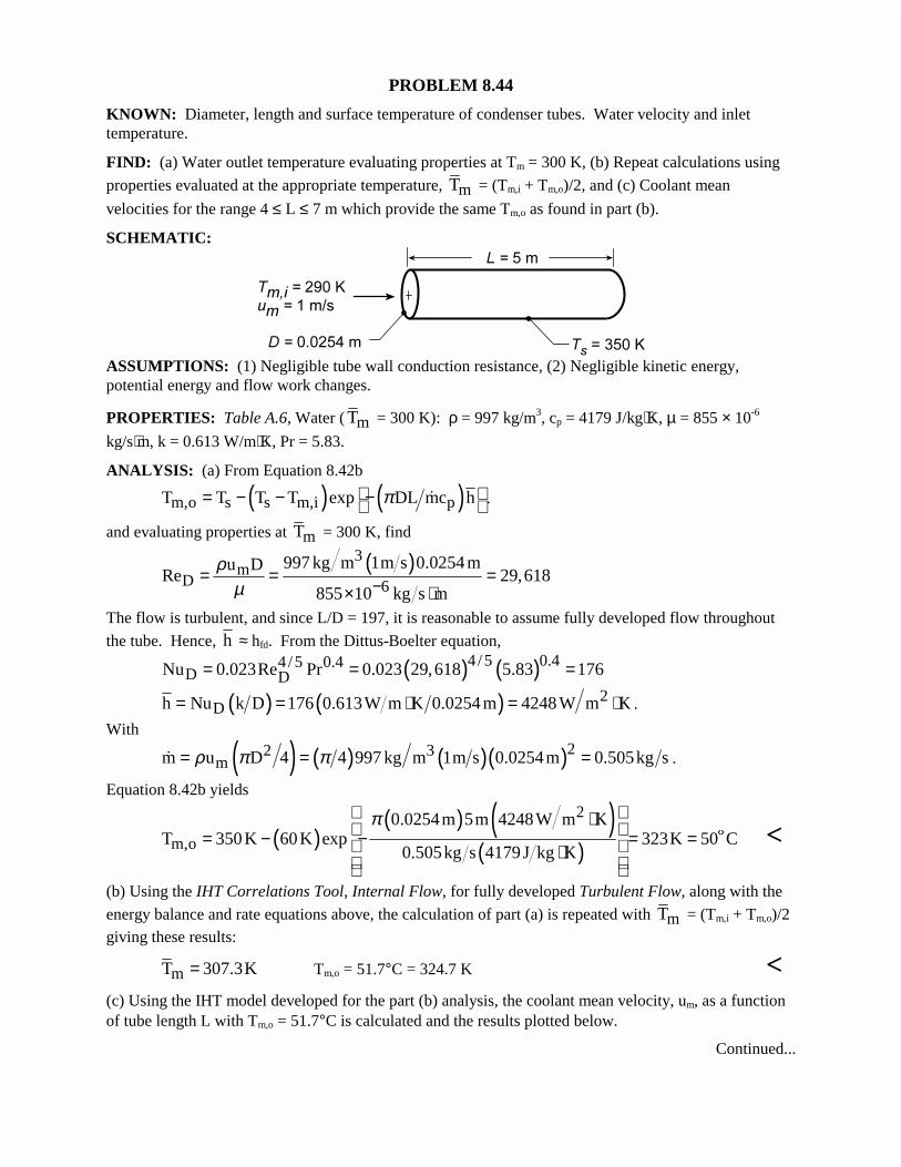
PROBLEM 8.44
KNOWN: Diameter, length and surface temperature of condenser tubes. Water velocity and inlettemperature.
FIND: (a) Water outlet temperature evaluating properties at Tm = 300 K, (b) Repeat calculations using
properties evaluated at the appropriate temperature, mT = (Tm,i + Tm,o)/2, and (c) Coolant mean
velocities for the range 4 ≤ L ≤ 7 m which provide the same Tm,o as found in part (b).
SCHEMATIC:
ASSUMPTIONS: (1) Negligible tube wall conduction resistance, (2) Negligible kinetic energy,potential energy and flow work changes.
PROPERTIES: Table A.6, Water ( mT = 300 K): ρ = 997 kg/m3, cp = 4179 J/kg⋅K, µ = 855 × 10-6
kg/s⋅m, k = 0.613 W/m⋅K, Pr = 5.83.
ANALYSIS: (a) From Equation 8.42b
( ) ( )m,o s s m,i pT T T T exp DL mc hπ = − − − � .
and evaluating properties at mT = 300 K, find
( )3m
D 6
997 kg m 1m s 0.0254 mu DRe 29,618
855 10 kg s m
ρµ −= = =
× ⋅The flow is turbulent, and since L/D = 197, it is reasonable to assume fully developed flow throughout
the tube. Hence, h ≈ hfd. From the Dittus-Boelter equation,
( ) ( )4 /5 0.44 /5 0.4D DNu 0.023Re Pr 0.023 29,618 5.83 176= = =
( ) ( ) 2Dh Nu k D 176 0.613W m K 0.0254 m 4248 W m K= = ⋅ = ⋅ .
With
( ) ( ) ( )( )22 3mm u D 4 4 997 kg m 1m s 0.0254m 0.505kg sρ π π= = =� .
Equation 8.42b yields
( )( ) ( )
( )
2
m,o
0.0254m 5m 4248W m KT 350K 60K exp 323K 50 C
0.505kg s 4179J kg K
π ⋅ = − − = = ⋅
$ <
(b) Using the IHT Correlations Tool, Internal Flow, for fully developed Turbulent Flow, along with the
energy balance and rate equations above, the calculation of part (a) is repeated with mT = (Tm,i + Tm,o)/2giving these results:
mT 307.3K= Tm,o = 51.7°C = 324.7 K <(c) Using the IHT model developed for the part (b) analysis, the coolant mean velocity, um, as a functionof tube length L with Tm,o = 51.7°C is calculated and the results plotted below.
Continued...
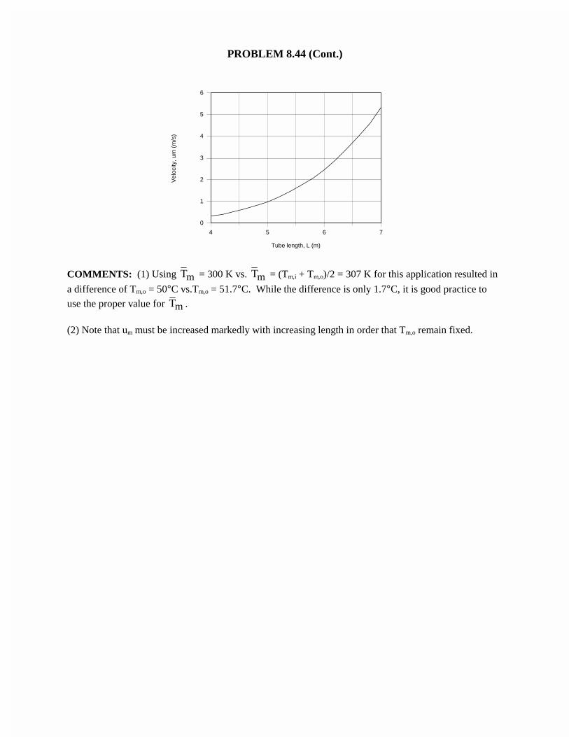
PROBLEM 8.44 (Cont.)
4 5 6 7
Tube length, L (m)
0
1
2
3
4
5
6
Vel
ocity
, um
(m
/s)
COMMENTS: (1) Using mT = 300 K vs. mT = (Tm,i + Tm,o)/2 = 307 K for this application resulted in
a difference of Tm,o = 50°C vs.Tm,o = 51.7°C. While the difference is only 1.7°C, it is good practice to
use the proper value for mT .
(2) Note that um must be increased markedly with increasing length in order that Tm,o remain fixed.
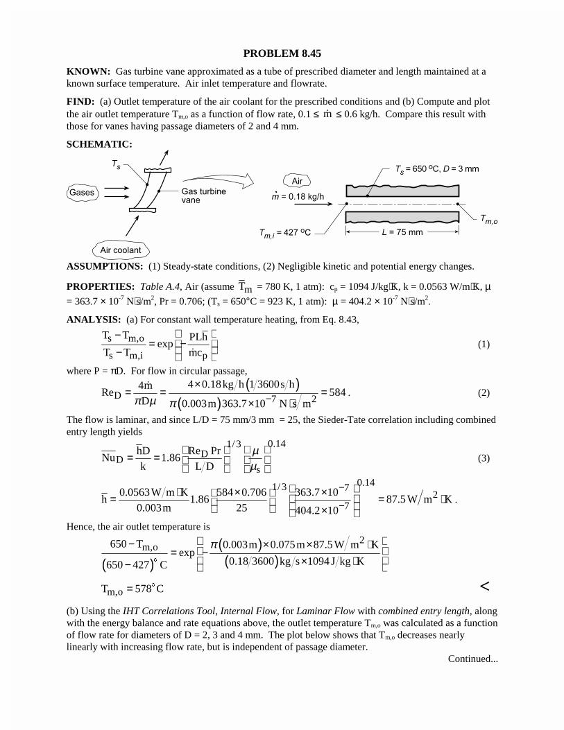
PROBLEM 8.45
KNOWN: Gas turbine vane approximated as a tube of prescribed diameter and length maintained at aknown surface temperature. Air inlet temperature and flowrate.
FIND: (a) Outlet temperature of the air coolant for the prescribed conditions and (b) Compute and plotthe air outlet temperature Tm,o as a function of flow rate, 0.1 ≤ m� ≤ 0.6 kg/h. Compare this result withthose for vanes having passage diameters of 2 and 4 mm.
SCHEMATIC:
ASSUMPTIONS: (1) Steady-state conditions, (2) Negligible kinetic and potential energy changes.
PROPERTIES: Table A.4, Air (assume mT = 780 K, 1 atm): cp = 1094 J/kg⋅K, k = 0.0563 W/m⋅K, µ= 363.7 × 10⁻⁷ N⋅s/m2, Pr = 0.706; (Ts = 650°C = 923 K, 1 atm): µ = 404.2 × 10⁻⁷ N⋅s/m2.
ANALYSIS: (a) For constant wall temperature heating, from Eq. 8.43,
s m,o
s m,i p
T T PLhexp
T T mc
−= − − �
(1)
where P = πD. For flow in circular passage,
( )( )D 7 2
4 0.18kg h 1 3600s h4mRe 584
D 0.003m 363.7 10 N s mπ µ π −×
= = =× ⋅
�. (2)
The flow is laminar, and since L/D = 75 mm/3 mm = 25, the Sieder-Tate correlation including combinedentry length yields
0.141/3D
Ds
hD Re PrNu 1.86
k L D
µµ
= =
(3)
0.141/3 72
70.0563W m K 584 0.706 363.7 10
h 1.86 87.5 W m K0.003m 25 404.2 10
−
−
⋅ × × = = ⋅ × .
Hence, the air outlet temperature is
( )( )( )
2m,o650 T 0.003m 0.075m 87.5W m K
exp0.18 3600 kg s 1094 J kg K650 427 C
π − × × ⋅ = − × ⋅−
$
m,oT 578 C= $ <(b) Using the IHT Correlations Tool, Internal Flow, for Laminar Flow with combined entry length, alongwith the energy balance and rate equations above, the outlet temperature Tm,o was calculated as a functionof flow rate for diameters of D = 2, 3 and 4 mm. The plot below shows that Tm,o decreases nearlylinearly with increasing flow rate, but is independent of passage diameter.
Continued...
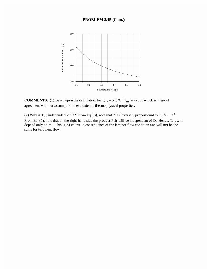
PROBLEM 8.45 (Cont.)
0.1 0.2 0.3 0.4 0.5 0.6
Flow rate, mdot (kg/h)
500
550
600
650
Out
let t
empe
ratu
re, T
mo
(C)
COMMENTS: (1) Based upon the calculation for Tm,o = 578°C, mT = 775 K which is in goodagreement with our assumption to evaluate the thermophysical properties.
(2) Why is Tm,o independent of D? From Eq. (3), note that h is inversely proportional to D, h ~ D-1.
From Eq. (1), note that on the right-hand side the product P⋅ h will be independent of D. Hence, Tm,o willdepend only on �m . This is, of course, a consequence of the laminar flow condition and will not be thesame for turbulent flow.
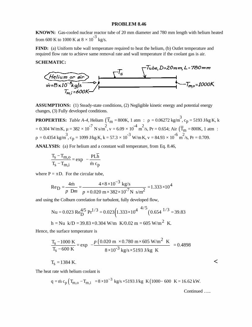
PROBLEM 8.46
KNOWN: Gas-cooled nuclear reactor tube of 20 mm diameter and 780 mm length with helium heated
from 600 K to 1000 K at 8 × 10⁻³
kg/s.
FIND: (a) Uniform tube wall temperature required to heat the helium, (b) Outlet temperature andrequired flow rate to achieve same removal rate and wall temperature if the coolant gas is air.
SCHEMATIC:
ASSUMPTIONS: (1) Steady-state conditions, (2) Negligible kinetic energy and potential energychanges, (3) Fully developed conditions.
PROPERTIES: Table A-4, Helium ( )mT 800K, 1 atm := ρ = 0.06272 kg/m3, cp = 5193 J/kg⋅K, k
= 0.304 W/m⋅K, µ = 382 × 10-7
N⋅s/m2, ν = 6.09 × 10
-4 m
2/s, Pr = 0.654; Air ( )mT 800K, 1 atm :=
ρ = 0.4354 kg/m3, cp = 1099 J/kg⋅K, k = 57.3 × 10
-3 W/m⋅K, ν = 84.93 × 10
-6 m
2/s, Pr = 0.709.
ANALYSIS: (a) For helium and a constant wall temperature, from Eq. 8.46,
s m,o
s m,i p
T T PLhexp
T T m c
−= − − &
where P = πD. For the circular tube,
34
D -7 24m 4 8 10 kg/s
Re 1.333 10 D 0.020 m 382 10 N s/mπ µ π
−× ×= = = ×× × × ⋅
&
and using the Colburn correlation for turbulent, fully developed flow,
( ) ( )4/5 1/34/5 1/3 4
DNu 0.023 Re Pr 0.023 1.333 10 0.654 39.83= = × =
2h Nu k/D 39.83 0.304 W/m K/0.02 m 605 W/m K.= ⋅ = × ⋅ = ⋅Hence, the surface temperature is
( ) 2s
-3s
0.020 m 0.780 m 605 W/m KT 1000 Kexp 0.4898
T 600 K 8 10 kg/s 5193 J/kg K
π × × ⋅− = − =− × × ⋅
sT 1384 K.= <The heat rate with helium coolant is
( ) ( )3p m,o m,iq m c T T 8 10 kg/s 5193 J/kg K 1000 600 K 16.62 kW.−= − = × × ⋅ − =&
Continued …..
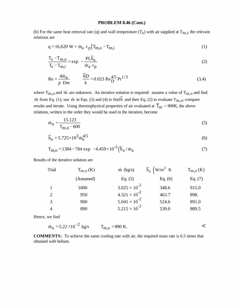
PROBLEM 8.46 (Cont.)
(b) For the same heat removal rate (q) and wall temperature (Ts) with air supplied at Tm,i, the relevantrelations are
( )a p m,o m,iq 16,620 W m c T T= = −& (1)
s m,o a
s m,i a p
T T PLhexp
T T m c
−= −
− &(2)
4/5 1/3aD
4m hDRe 0.023 Re Pr
D kπ µ= =
& (3,4)
where Tm,o and m& are unknown. An iterative solution is required: assume a value of Tm,o and find
&m from Eq. (1); use m& in Eqs. (3) and (4) to findh and then Eq. (2) to evaluate Tm,o; compareresults and iterate. Using thermophysical properties of air evaluated at mT = 800K, the aboverelations, written in the order they would be used in the iteration, become
am,o
15.123m
T 600=
−& (5)
3 4/5a ah 5.725 10 m= × & (6)
( )-5m,o a aT 1384 784 exp 4.459 10 h / m = − − ×
& (7)
Results of the iterative solution are
Trial Tm,o (K) m& (kg/s) ( )2ah W/m K⋅ Tm,o (K)
(Assumed) Eq. (5) Eq. (6) Eq. (7)
1 1000 3.025 × 10⁻²
348.6 915.0
2 950 4.321 × 10⁻²
463.7 898.
3 900 5.041 × 10⁻²
524.6 891.0
4 890 5.215 × 10⁻²
539.0 889.5
Hence, we find
2a m,om 5.22 10 kg/s T 890 K.−= × =& <
COMMENTS: To achieve the same cooling rate with air, the required mass rate is 6.5 times thatobtained with helium.
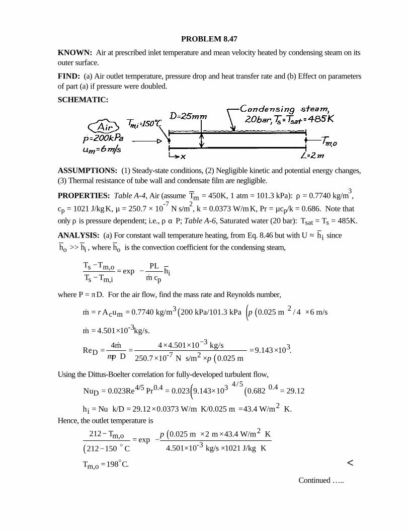
PROBLEM 8.47
KNOWN: Air at prescribed inlet temperature and mean velocity heated by condensing steam on itsouter surface.
FIND: (a) Air outlet temperature, pressure drop and heat transfer rate and (b) Effect on parametersof part (a) if pressure were doubled.
SCHEMATIC:
ASSUMPTIONS: (1) Steady-state conditions, (2) Negligible kinetic and potential energy changes,(3) Thermal resistance of tube wall and condensate film are negligible.
PROPERTIES: Table A-4, Air (assume Tm = 450K, 1 atm = 101.3 kPa): ρ = 0.7740 kg/m3,
cp = 1021 J/kg⋅K, µ = 250.7 × 10⁻⁷
N⋅s/m2, k = 0.0373 W/m⋅K, Pr = µcp/k = 0.686. Note that
only ρ is pressure dependent; i.e., ρ α P; Table A-6, Saturated water (20 bar): Tsat = Ts = 485K.
ANALYSIS: (a) For constant wall temperature heating, from Eq. 8.46 but with U ≈ ih since
o i oh h , where h>> is the convection coefficient for the condensing steam,
s m,oi
s m,i p
T T PLexp h
T T m c
−= − − &
where P = πD. For the air flow, find the mass rate and Reynolds number,
( ) ( )( )23c mm A u 0.7740 kg/m 200 kPa/101.3 kPa 0.025 m / 4 6 m/sρ π= = ×&
-3m 4.501 10 kg/s.= ×&
( )
33
D -7 24m 4 4.501 10 kg/s
Re 9.143 10 . D 250.7 10 N s/m 0.025 mµπ π
−× ×= = = ×× ⋅ ×
&
Using the Dittus-Boelter correlation for fully-developed turbulent flow,
( ) ( )4/5 0.44/5 0.4 3
DNu 0.023Re Pr 0.023 9.143 10 0.682 29.12= = × =
2ih Nu k/D 29.12 0.0373 W/m K/0.025 m 43.4 W/m K.= ⋅ = × ⋅ = ⋅
Hence, the outlet temperature is
( )( ) 2
m,o-3
212 T 0.025 m 2 m 43.4 W/m Kexp
4.501 10 kg/s 1021 J/kg K212 150 C
π − × × ⋅ = − × × ⋅−
o
m,oT 198 C.= o <Continued …..
PROBLEM 8.47 (Cont.)
The pressure drop follows from Eqs. 8.20 and 8.22,
( ) 1/41/4 3Df 0.316Re 0.316 9.143 10 0.0323
−−= = × =
2mu
p f L2D
ρ∆ =
( ) ( )2320.7740 kg/m 200/101.3 6 m/s 2 m
p 0.0323 71.1 N/m .2 0.025 m
×∆ = =
×<
The heat transfer rate is
( ) ( )3p m,o m,iq m c T T 4.501 10 kg/s 1021 J/kg K 198 150 K 221 W.−= − = × × ⋅ − =& <
(b) If the pressure were doubled, we can see from the above relations, that &m ,α ρ hence
om 2m=& &
D D,oRe 2Re ,=
since
( ) ( )4/5 4/5i i i,oh Re h / h 2 ,∝ → =
i i,oh 1.74h .=
It follows that Tm,o = 195°C, so that the effect on temperature is slight. However, the pressure
drop increases by the factor 2(2)-1/4
= 1.68 and the heat rate by 2(195 - 150)/(198 - 150) = 1.88.In summary:
Parameter p = 200 kPa p = 400 kPa Increase, % Part (a) Part (b)
&m, kg/s × 103
4.501 9.002 100
hi, W/m2⋅K 43.4 86.8 100
Tmo - Tm,i°C 48 45 -6
∆p, N/m2
71.1 119 68q, W 221 415 88
COMMENTS: (1) Note that mT = (198 + 150)°C/2 = 447 K agrees well with the assumedvalue (450 K) used to evaluate the thermophysical properties.
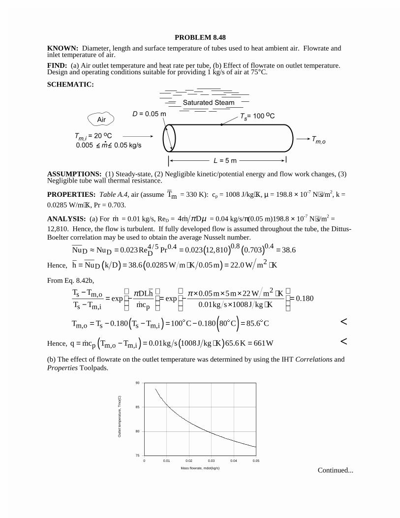
PROBLEM 8.48
KNOWN: Diameter, length and surface temperature of tubes used to heat ambient air. Flowrate andinlet temperature of air.
FIND: (a) Air outlet temperature and heat rate per tube, (b) Effect of flowrate on outlet temperature.Design and operating conditions suitable for providing 1 kg/s of air at 75°C.
SCHEMATIC:
ASSUMPTIONS: (1) Steady-state, (2) Negligible kinetic/potential energy and flow work changes, (3)Negligible tube wall thermal resistance.
PROPERTIES: Table A.4, air (assume mT = 330 K): cp = 1008 J/kg⋅K, µ = 198.8 × 10⁻⁷ N⋅s/m2, k =
0.0285 W/m⋅K, Pr = 0.703.
ANALYSIS: (a) For m� = 0.01 kg/s, ReD = 4m Dπ µ� = 0.04 kg/s/π(0.05 m)198.8 × 10⁻⁷ N⋅s/m2 =12,810. Hence, the flow is turbulent. If fully developed flow is assumed throughout the tube, the Dittus-Boelter correlation may be used to obtain the average Nusselt number.
( ) ( )0.8 0.44 /5 0.4D D DNu Nu 0.023Re Pr 0.023 12,810 0.703 38.6≈ = = =
Hence, ( ) ( ) 2Dh Nu k D 38.6 0.0285W m K 0.05m 22.0 W m K= = ⋅ = ⋅
From Eq. 8.42b,2
s m,o
s m,i p
T T DLh 0.05m 5m 22 W m Kexp exp 0.180
T T mc 0.01kg s 1008J kg K
π π − × × × ⋅ = − = − = − × ⋅ �
( ) ( )m,o s s m,iT T 0.180 T T 100 C 0.180 80 C 85.6 C= − − = − =$ $ $ <
Hence, ( ) ( )p m,o m,iq mc T T 0.01kg s 1008J kg K 65.6 K 661W= − = ⋅ =� <(b) The effect of flowrate on the outlet temperature was determined by using the IHT Correlations andProperties Toolpads.
0 0.01 0.02 0.03 0.04 0.05
Mass flowrate, mdot(kg/s)
75
80
85
90
Out
let t
empe
ratu
re, T
mo(
C)
Continued...
PROBLEM 8.48 (Cont.)
Although h and hence the heat rate increase with increasing m� , the increase in q is not linearlyproportional to the increase in �m and Tm,o decreases with increasing �m .
A flowrate of m� = 0.05 kg/s is not large enough to provide the desired outlet temperature of75°C, and to achieve this value, a flowrate of 0.0678 kg/s would be needed. At such a flowrate,N = 1 kg/s/0.0678 kg/s = 14.75 ≈ 15 tubes would be needed to satisfy the process airrequirement. Alternatively, a lower flowrate could be supplied to a larger number of tubes andthe discharge mixed with ambient air to satisfy the desired conditions. Requirements of thisoption are that
ambNm m 1kg / s+ =� �
( ) ( ) ( )amb p m,o m,iNm m c T T 1kg s 1008J kg K 75 20 K 55, 400 W+ − = × ⋅ − =� �
where m� is the flowrate per tube. Using a larger number of tubes with a smaller flowrate pertube would reduce flow pressure losses and hence provide for reduced operating costs.
COMMENTS: With L/D = 5 m/0.05 m = 100, the assumption of fully developed conditionsthroughout the tube is reasonable.
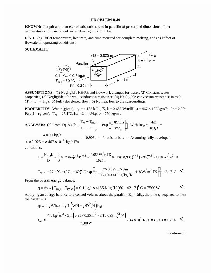
PROBLEM 8.49
KNOWN: Length and diameter of tube submerged in paraffin of prescribed dimensions. Inlettemperature and flow rate of water flowing through tube.
FIND: (a) Outlet temperature, heat rate, and time required for complete melting, and (b) Effect offlowrate on operating conditions.
SCHEMATIC:
ASSUMPTIONS: (1) Negligible KE/PE and flowwork changes for water, (2) Constant waterproperties, (3) Negligible tube wall conduction resistance, (4) Negligible convection resistance in melt(Ts = T
�
= Tmp), (5) Fully developed flow, (6) No heat loss to the surroundings.
PROPERTIES: Water (given): cp = 4.185 kJ/kg⋅K, k = 0.653 W/m⋅K, µ = 467 × 10-6 kg/s⋅m, Pr = 2.99;Paraffin (given): Tmp = 27.4°C, hsf = 244 kJ/kg, ρ = 770 kg/m3.
ANALYSIS: (a) From Eq. 8.42b, m,o
m,i p
T T DLhexp
T T mc
π∞
∞
−= − − �
. With ReD = 4m
Dπ µ�
=
64 0.1kg s
0.025m 467 10 kg s mπ −×
× × × ⋅ = 10,906, the flow is turbulent. Assuming fully developed
conditions,
( ) ( )4 / 5 0.3 24 / 5 0.3DD
Nu k k 0.653 W m Kh 0.023 Re Pr 0.023 10,906 2.99 1418 W m K
D D 0.025 m
⋅= = = = ⋅
( ) 2m,o
0.025 m 3mT 27.4 C 27.4 60 C exp 1418 W m K 42.17 C
0.1kg s 4185 J kg K
π× ×= − − − ⋅ =
× ⋅
$$ $ <From the overall energy balance,
( ) ( )p m,i m,oq mc T T 0.1kg s 4185J kg K 60 42.17 C 7500 W= − = × ⋅ − =$
� <Applying an energy balance to a control volume about the paraffin, Ein = ∆Est, the time tm required to meltthe paraffin is
( )2m sf sfqt Vh L WH D 4 hρ ρ ρ= = −
( )( )23 25
m
770 kg m 3m 0.25 0.25m 0.025 m 4t 2.44 10 J kg 4660s 1.29 h
7500 W
π× × −= × = = <
Continued...

PROBLEM 8.49 (Cont.)
(b) The effect of m� on q and Tm,o was determined by accessing the Correlations Toolpad of IHT, and theresults are plotted as follows.
0.1 0.2 0.3 0.4 0.5
Mass flowrate, mdot(kg/s)
5000
10000
15000
20000
25000
30000
Hea
t rat
e, q
(W)
0.1 0.2 0.3 0.4 0.5
Mass flowrate, mdot(kg/s)
42
43
44
45
46
Out
let
tem
pera
ture
, T
mo(
C)
Although q increases with increasing m� due to the attendant increase in ReD, and therefore h , theincrease is not linearly proportional to the change in m� . Hence, from the overall energy balance, q =m� cp(Tm,i - Tm,o), there is a reduction in (Tm,i - Tm,o), which corresponds to an increase in Tm,o. With theincrease in q, there is a reduction in tm, and for m� = 0.5 kg/s,
mt 1167s 0.324 h= = <COMMENTS: Heat transfer from the water to the paraffin is also affected by free convection in themelt region around the tube. The effect is to decrease U, increase Ts, and decrease q with increasingtime. The actual time to achieve complete melting would exceed values computed in the foregoinganalysis.
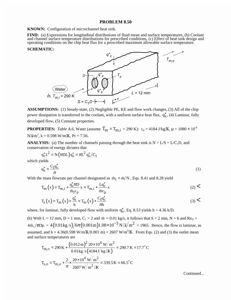
PROBLEM 8.50
KNOWN: Configuration of microchannel heat sink.
FIND: (a) Expressions for longitudinal distributions of fluid mean and surface temperatures, (b) Coolantand channel surface temperature distributions for prescribed conditions, (c) Effect of heat sink design andoperating conditions on the chip heat flux for a prescribed maximum allowable surface temperature.
SCHEMATIC:
ASSUMPTIONS: (1) Steady-state, (2) Negligible PE, KE and flow work changes, (3) All of the chippower dissipation is transferred to the coolant, with a uniform surface heat flux, sq′′ , (4) Laminar, fully
developed flow, (5) Constant properties.
PROPERTIES: Table A.6, Water (assume m m,iT T= = 290 K): cp = 4184 J/kg⋅K, µ = 1080 × 10-6
N⋅s/m2, k = 0.598 W/m⋅K, Pr = 7.56.
ANALYSIS: (a) The number of channels passing through the heat sink is N = L/S = L/C1D, andconservation of energy dictates that
( )2 2c s s 1q L N DL q L q Cπ π′′ ′′ ′′= =
which yields
1 cs
C qq
π′′
′′ = (1)
With the mass flowrate per channel designated as 1m m N=� � , Eqs. 8.41 and 8.28 yield
( ) s cm m,i m,i
1 p p
q D LqT x T x T x
m c mc
π′′ ′′= + = +
� �
(2) <
( ) ( ) ( )s 1 cs m m
q C qT x T x T x
h hπ′′ ′′
= + = + (3) <where, for laminar, fully developed flow with uniform sq′′ , Eq. 8.53 yields h = 4.36 k/D.
(b) With L = 12 mm, D = 1 mm, C1 = 2 and �m = 0.01 kg/s, it follows that S = 2 mm, N = 6 and ReD =
4 1�m DS P = ( ) ( ) 3 24 0.01kg s 6 0.001m 1.08 10 N s mπ −× ⋅ = 1965. Hence, the flow is laminar, as
assumed, and h = 4.36(0.598 W/m⋅K/0.001 m) = 2607 W/m2⋅K. From Eqs. (2) and (3) the outlet meanand surface temperatures are
( )( )
2 4 2
m,o0.012 m 20 10 W m
T 290 K 290.7 K 17.7 C0.01kg s 4184 J kg K
×= + = =
⋅$
4 2
s,o m,o 2
2 20 10 W mT T 339.5K 66.5 C
2607 W m Kπ×
= + × = =⋅
$
Continued...
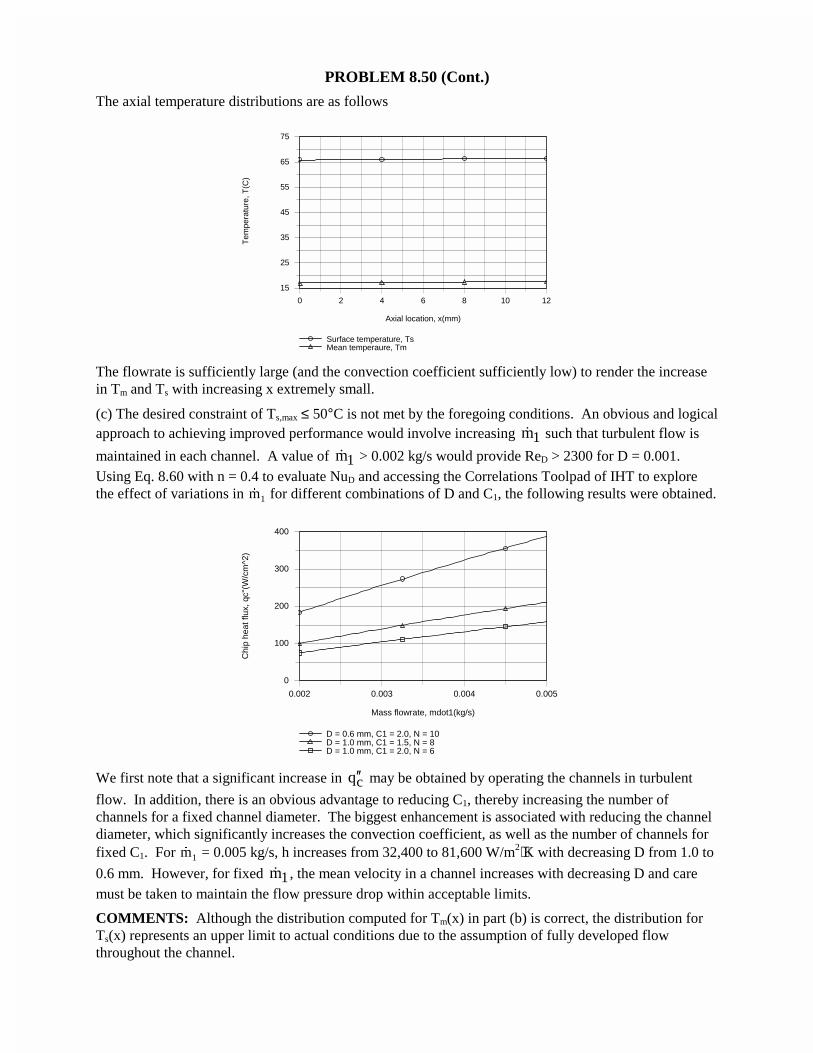
PROBLEM 8.50 (Cont.)
The axial temperature distributions are as follows
0 2 4 6 8 10 12
Axial location, x(mm)
15
25
35
45
55
65
75
Tem
pera
ture
, T(C
)
Surface temperature, TsMean temperaure, Tm
The flowrate is sufficiently large (and the convection coefficient sufficiently low) to render the increasein Tm and Ts with increasing x extremely small.
(c) The desired constraint of Ts,max ≤ 50°C is not met by the foregoing conditions. An obvious and logicalapproach to achieving improved performance would involve increasing 1m� such that turbulent flow is
maintained in each channel. A value of 1m� > 0.002 kg/s would provide ReD > 2300 for D = 0.001.Using Eq. 8.60 with n = 0.4 to evaluate NuD and accessing the Correlations Toolpad of IHT to explorethe effect of variations in �m1 for different combinations of D and C1, the following results were obtained.
0.002 0.003 0.004 0.005
Mass flowrate, mdot1(kg/s)
0
100
200
300
400
Chi
p he
at fl
ux, q
c''(W
/cm
^2)
D = 0.6 mm, C1 = 2.0, N = 10D = 1.0 mm, C1 = 1.5, N = 8D = 1.0 mm, C1 = 2.0, N = 6
We first note that a significant increase in cq′′ may be obtained by operating the channels in turbulent
flow. In addition, there is an obvious advantage to reducing C1, thereby increasing the number ofchannels for a fixed channel diameter. The biggest enhancement is associated with reducing the channeldiameter, which significantly increases the convection coefficient, as well as the number of channels forfixed C1. For �m1 = 0.005 kg/s, h increases from 32,400 to 81,600 W/m2⋅K with decreasing D from 1.0 to
0.6 mm. However, for fixed 1m� , the mean velocity in a channel increases with decreasing D and caremust be taken to maintain the flow pressure drop within acceptable limits.
COMMENTS: Although the distribution computed for Tm(x) in part (b) is correct, the distribution forTs(x) represents an upper limit to actual conditions due to the assumption of fully developed flowthroughout the channel.
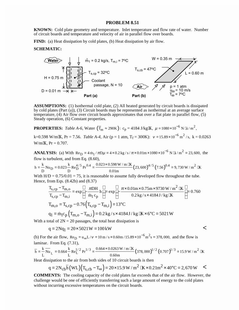
PROBLEM 8.51
KNOWN: Cold plate geometry and temperature. Inlet temperature and flow rate of water. Numberof circuit boards and temperature and velocity of air in parallel flow over boards.
FIND: (a) Heat dissipation by cold plates, (b) Heat dissipation by air flow.
SCHEMATIC:
ASSUMPTIONS: (1) Isothermal cold plate, (2) All heated generated by circuit boards is dissipatedby cold plates (Part (a)), (3) Circuit boards may be represented as isothermal at an average surfacetemperature, (4) Air flow over circuit boards approximates that over a flat plate in parallel flow, (5)Steady operation, (6) Constant properties.
PROPERTIES: Table A-6, Water ( )mT 290K :≈ cp = 4184 J/kg⋅K, 6 21080 10 N s / m ,µ −= × ⋅
k=0.598 W/m⋅K, Pr = 7.56. Table A-4, Air (p = 1 atm, Tf = 300K): 6 215.89 10 m / s,ν −= × k = 0.0263
W/m⋅K, Pr = 0.707.
ANALYSIS: (a) With 6 2D 1Re 4 m / D 4 0.2 kg / s / 0.01m 1080 10 N s / m 23, 600,π µ π −= = × × × × ⋅ =� the
flow is turbulent, and from Eq. (8.60),
( ) ( )4 / 5 0.4 24 / 5 0.4D D
k k 0.023 0.598 W / m Kh Nu 0.023 Re Pr 23, 600 7.56 9, 730 W / m K
D D 0.01m
× ⋅= = = = ⋅
With H/D = 0.75/0.01 = 75, it is reasonable to assume fully developed flow throughout the tube.Hence, from Eqs. (8.42b) and (8.37)
2s,cp m,o
s,cp m,i 1 p
T T DH 0.01m 0.75m 9730 W / m Kexp h exp 0.760
T T m c 0.2 kg / s 4184 J / kg K
π π− × × × ⋅= − = − =
− × ⋅
�
( )m,o s,cp s,cp m,iT T 0.76 T T 13 C= − − = °
( )1 1 p m,o m,iq m c T T 0.2 kg / s 4184J / kg K 6 C 5021W= − = × ⋅ × ° =�
With a total of 2N = 20 passages, the total heat dissipation is
1q 2Nq 20 5021W 100 kW= = × = <(b) For the air flow, 6 2
DRe u L / 10 m / s 0.60m /15.89 10 m s 378, 000,ν −∞= = × × = and the flow is
laminar. From Eq. (7.31),
( ) ( )L1/ 2 1/ 3 21/ 2 1/ 3L
k k 0.664 0.0263 W / m Kh Nu 0.664 Re Pr 378, 000 0.707 15.9 W / m K
L L 0.60m
× ⋅= = = = ⋅
Heat dissipation to the air from both sides of 10 circuit boards is then
( )( ) 2 2cb s,cbq 2N h WL T T 20 15.9 W / m K 0.21m 40 C 2,670 W∞= − = × ⋅ × × ° = <
COMMENTS: The cooling capacity of the cold plates far exceeds that of the air flow. However, thechallenge would be one of efficiently transferring such a large amount of energy to the cold plateswithout incurring excessive temperatures on the circuit boards.
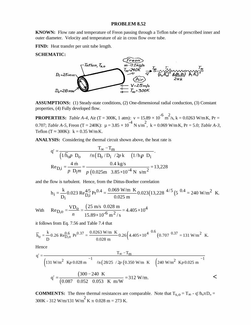
PROBLEM 8.52
KNOWN: Flow rate and temperature of Freon passing through a Teflon tube of prescribed inner andouter diameter. Velocity and temperature of air in cross flow over tube.
FIND: Heat transfer per unit tube length.
SCHEMATIC:
ASSUMPTIONS: (1) Steady-state conditions, (2) One-dimensional radial conduction, (3) Constantproperties, (4) Fully developed flow.
PROPERTIES: Table A-4, Air (T = 300K, 1 atm): ν = 15.89 × 10⁻⁶
m2/s, k = 0.0263 W/m⋅K, Pr =
0.707; Table A-5, Freon (T = 240K): µ = 3.85 × 10⁻⁴
N⋅s/m2, k = 0.069 W/m⋅K, Pr = 5.0; Table A-3,
Teflon (T ≈ 300K): k = 0.35 W/m⋅K.
ANALYSIS: Considering the thermal circuit shown above, the heat rate is
( ) ( ) ( )m
o o o i i i
T Tq .
1/h D n D / D / 2 k 1/h Dπ π π∞ −′ =
+ + l
( )D,i -4 2i
4 m 0.4 kg/sRe 13,228
D 0.025m 3.85 10 N s/mπ µ π= = =
× ⋅
&
and the flow is turbulent. Hence, from the Dittus-Boelter correlation
( ) ( )4/5 0.44/5 0.4 2i D,i
i
k 0.069 W/m Kh 0.023 Re Pr 0.023 13,228 5 240 W/m K.
D 0.025 m⋅= = = ⋅
With( ) 4o
D,o -6 225 m/s 0.028 mVD
Re 4.405 1015.89 10 m / sν
= = = ××
it follows from Eq. 7.56 and Table 7.4 that
( ) ( )0.6 0.370.6 0.37 4 2
o D,ok 0.0263 W/m K
h 0.26 Re Pr 0.26 4.405 10 0.707 131 W/m K.D 0.028 m
⋅= = × = ⋅
Hence
( ) ( ) ( ) ( )m
1 12 2
T Tq
131 W/m K 0.028 m n 28/25 / 2 0.350 W/m K 240 W/m K 0.025 mπ π π
∞− −
−′ =
⋅ + ⋅ + ⋅l
( )( )
300 240 Kq 312 W/m.
0.087 0.052 0.053 K m/W
−′ = =
+ + ⋅<
COMMENTS: The three thermal resistances are comparable. Note that Ts,o = T∞ - q′/hoπDo =
300K - 312 W/m/131 W/m2⋅K π 0.028 m = 273 K.
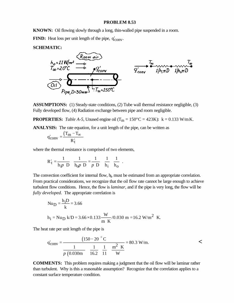
PROBLEM 8.53
KNOWN: Oil flowing slowly through a long, thin-walled pipe suspended in a room.
FIND: Heat loss per unit length of the pipe, convq .′
SCHEMATIC:
ASSUMPTIONS: (1) Steady-state conditions, (2) Tube wall thermal resistance negligible, (3)Fully developed flow, (4) Radiation exchange between pipe and room negligible.
PROPERTIES: Table A-5, Unused engine oil (Tm = 150°C = 423K): k = 0.133 W/m⋅K.
ANALYSIS: The rate equation, for a unit length of the pipe, can be written as( )m
convt
T Tq
R∞−
′ =′
where the thermal resistance is comprised of two elements,
ti o i o
1 1 1 1 1R .
h D h D D h hπ π π
′ = + = +
The convection coefficient for internal flow, hi, must be estimated from an appropriate correlation.From practical considerations, we recognize that the oil flow rate cannot be large enough to achieveturbulent flow conditions. Hence, the flow is laminar, and if the pipe is very long, the flow will befully developed. The appropriate correlation is
iD
h DNu 3.66
k= =
2i D
Wh Nu k/D 3.66 0.133 /0.030 m 16.2 W/m K.
m K= = × = ⋅
⋅
The heat rate per unit length of the pipe is
( )
( )
conv 2150 20 C
q 80.3 W/m.1 1 1 m K
0.030m 16.2 11 Wπ
−′ = =
⋅ +
o
<
COMMENTS: This problem requires making a judgment that the oil flow will be laminar ratherthan turbulent. Why is this a reasonable assumption? Recognize that the correlation applies to aconstant surface temperature condition.
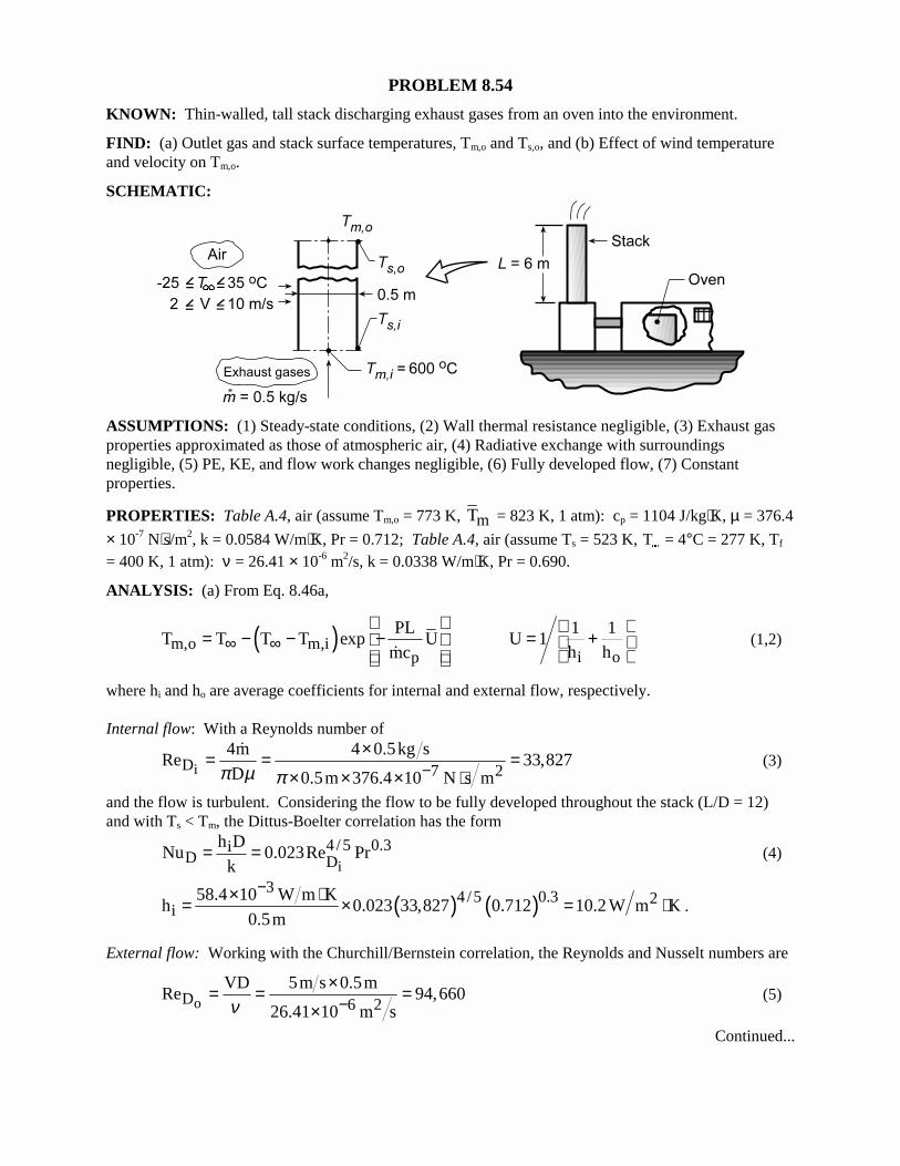
PROBLEM 8.54
KNOWN: Thin-walled, tall stack discharging exhaust gases from an oven into the environment.
FIND: (a) Outlet gas and stack surface temperatures, Tm,o and Ts,o, and (b) Effect of wind temperatureand velocity on Tm,o.
SCHEMATIC:
ASSUMPTIONS: (1) Steady-state conditions, (2) Wall thermal resistance negligible, (3) Exhaust gasproperties approximated as those of atmospheric air, (4) Radiative exchange with surroundingsnegligible, (5) PE, KE, and flow work changes negligible, (6) Fully developed flow, (7) Constantproperties.
PROPERTIES: Table A.4, air (assume Tm,o = 773 K, mT = 823 K, 1 atm): cp = 1104 J/kg⋅K, µ = 376.4
× 10-7 N⋅s/m2, k = 0.0584 W/m⋅K, Pr = 0.712; Table A.4, air (assume Ts = 523 K, T�
= 4°C = 277 K, Tf
= 400 K, 1 atm): ν = 26.41 × 10⁻⁶ m2/s, k = 0.0338 W/m⋅K, Pr = 0.690.
ANALYSIS: (a) From Eq. 8.46a,
( )m,o m,ip
PLT T T T exp U
mc∞ ∞
= − − − �
i o
1 1U 1
h h
= +
(1,2)
where hi and ho are average coefficients for internal and external flow, respectively.
Internal flow: With a Reynolds number of
iD 7 24m 4 0.5kg s
Re 33,827D 0.5m 376.4 10 N s mπ µ π −
×= = =× × × ⋅
�(3)
and the flow is turbulent. Considering the flow to be fully developed throughout the stack (L/D = 12)and with Ts < Tm, the Dittus-Boelter correlation has the form
i
4 /5 0.3iD D
h DNu 0.023Re Pr
k= = (4)
( ) ( )3
4 /5 0.3 2i
58.4 10 W m Kh 0.023 33,827 0.712 10.2 W m K
0.5m
−× ⋅= × = ⋅ .
External flow: Working with the Churchill/Bernstein correlation, the Reynolds and Nusselt numbers are
oD 6 2VD 5m s 0.5m
Re 94,66026.41 10 m sν −
×= = =×
(5)
Continued...
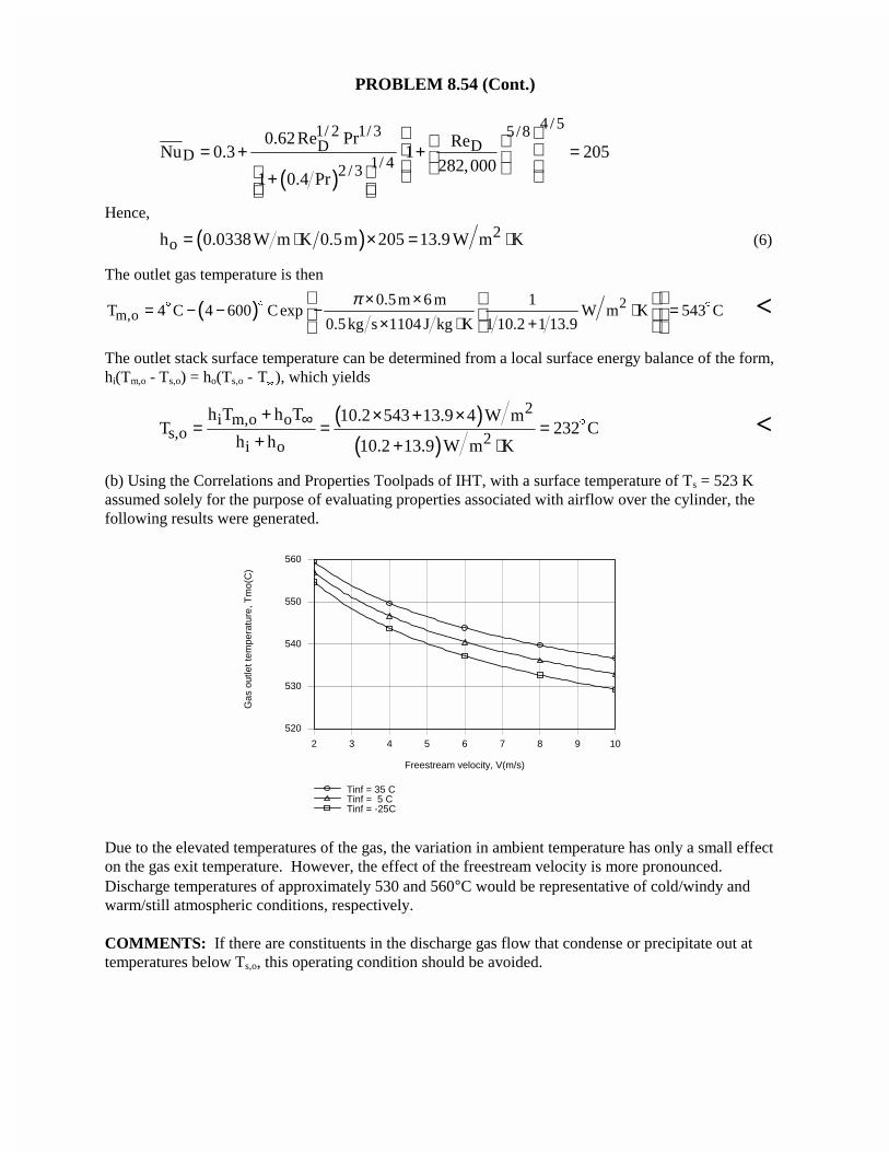
PROBLEM 8.54 (Cont.)
( )
4 /51/ 2 1/ 3 5/8DD
D 1/ 42 /3
0.62Re Pr ReNu 0.3 1 205
282,0001 0.4 Pr
= + + = + Hence,
( ) 2oh 0.0338W m K 0.5m 205 13.9 W m K= ⋅ × = ⋅ (6)
The outlet gas temperature is then
( ) 2m,o
0.5m 6 m 1T 4 C 4 600 C exp W m K 543 C
0.5kg s 1104 J kg K 1 10.2 1 13.9
π× ×= − − − ⋅ =
× ⋅ +
$$ $ <
The outlet stack surface temperature can be determined from a local surface energy balance of the form,hi(Tm,o - Ts,o) = ho(Ts,o - T
�
), which yields
( )( )
2i m,o o
s,o 2i o
h T h T 10.2 543 13.9 4 W mT 232 C
h h 10.2 13.9 W m K
∞+ × + ×= = =
+ + ⋅$ <
(b) Using the Correlations and Properties Toolpads of IHT, with a surface temperature of Ts = 523 Kassumed solely for the purpose of evaluating properties associated with airflow over the cylinder, thefollowing results were generated.
2 3 4 5 6 7 8 9 10
Freestream velocity, V(m/s)
520
530
540
550
560
Gas
out
let t
empe
ratu
re, T
mo(
C)
Tinf = 35 CTinf = 5 CTinf = -25C
Due to the elevated temperatures of the gas, the variation in ambient temperature has only a small effecton the gas exit temperature. However, the effect of the freestream velocity is more pronounced.Discharge temperatures of approximately 530 and 560°C would be representative of cold/windy andwarm/still atmospheric conditions, respectively.
COMMENTS: If there are constituents in the discharge gas flow that condense or precipitate out attemperatures below Ts,o, this operating condition should be avoided.
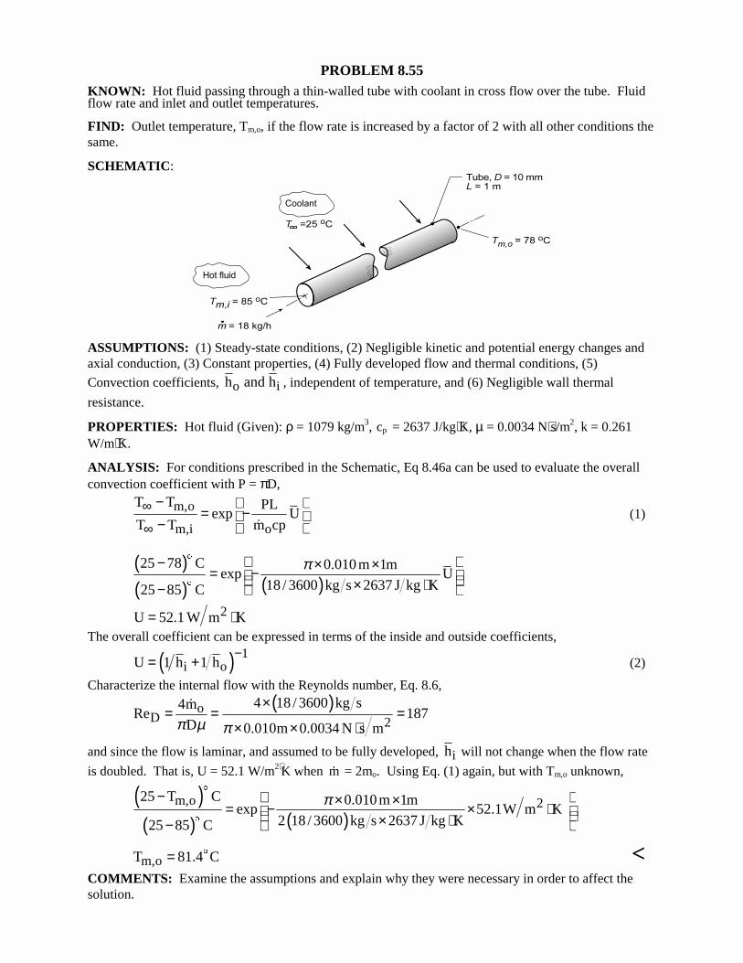
PROBLEM 8.55KNOWN: Hot fluid passing through a thin-walled tube with coolant in cross flow over the tube. Fluidflow rate and inlet and outlet temperatures.
FIND: Outlet temperature, Tm,o, if the flow rate is increased by a factor of 2 with all other conditions thesame.
SCHEMATIC:
ASSUMPTIONS: (1) Steady-state conditions, (2) Negligible kinetic and potential energy changes andaxial conduction, (3) Constant properties, (4) Fully developed flow and thermal conditions, (5)
Convection coefficients, o ih and h , independent of temperature, and (6) Negligible wall thermal
resistance.
PROPERTIES: Hot fluid (Given): ρ = 1079 kg/m3, cp = 2637 J/kg⋅K, µ = 0.0034 N⋅s/m2, k = 0.261W/m⋅K.
ANALYSIS: For conditions prescribed in the Schematic, Eq 8.46a can be used to evaluate the overallconvection coefficient with P = πD,
m,o
m,i o
T T PLexp U
T T m cp∞
∞
− = − − �
(1)
( )( ) ( )25 78 C 0.010 m 1m
exp U18 / 3600 kg s 2637 J kg K25 85 C
π − × ×= − × ⋅−
$
$
2U 52.1 W m K= ⋅The overall coefficient can be expressed in terms of the inside and outside coefficients,
( ) 1i oU 1 h 1 h
−= + (2)
Characterize the internal flow with the Reynolds number, Eq. 8.6,
( )oD 2
4 18 / 3600 kg s4mRe 187
D 0.010m 0.0034 N s mπ µ π
×= = =
× × ⋅
�
and since the flow is laminar, and assumed to be fully developed, ih will not change when the flow rate
is doubled. That is, U = 52.1 W/m2⋅K when �m = 2mo. Using Eq. (1) again, but with Tm,o unknown,
( )( ) ( )
m,o 225 T C 0.010 m 1mexp 52.1W m K
2 18/ 3600 kg s 2637 J kg K25 85 C
π− × ×= − × ⋅ × ⋅−
$
$
m,oT 81.4 C= $ <COMMENTS: Examine the assumptions and explain why they were necessary in order to affect thesolution.
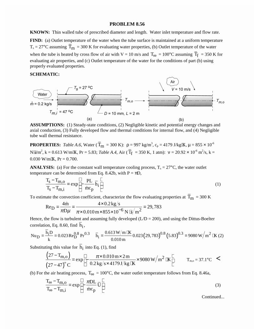
PROBLEM 8.56
KNOWN: Thin walled tube of prescribed diameter and length. Water inlet temperature and flow rate.
FIND: (a) Outlet temperature of the water when the tube surface is maintained at a uniform temperature
Ts = 27°C assuming mT = 300 K for evaluating water properties, (b) Outlet temperature of the water
when the tube is heated by cross flow of air with V = 10 m/s and T∞ = 100°C assuming fT = 350 K forevaluating air properties, and (c) Outlet temperature of the water for the conditions of part (b) usingproperly evaluated properties.
SCHEMATIC:
ASSUMPTIONS: (1) Steady-state conditions, (2) Negligible kinetic and potential energy changes andaxial conduction, (3) Fully developed flow and thermal conditions for internal flow, and (4) Negligibletube wall thermal resistance.
PROPERTIES: Table A.6, Water ( mT = 300 K): ρ = 997 kg/m3, cp = 4179 J/kg⋅K, µ = 855 × 10-6
N⋅s/m2, k = 0.613 W/m⋅K, Pr = 5.83; Table A.4, Air ( fT = 350 K, 1 atm): ν = 20.92 × 10⁻⁶ m2/s, k =
0.030 W/m⋅K, Pr = 0.700.
ANALYSIS: (a) For the constant wall temperature cooling process, Ts = 27°C, the water outlettemperature can be determined from Eq. 8.42b, with P = πD,
s m,oi
s m,i p
T T PLexp h
T T mc
−= − − �
(1)
To estimate the convection coefficient, characterize the flow evaluating properties at mT = 300 K
D 6 24m 4 0.2kg s
Re 29,783D 0.010 m 855 10 N s mπ µ π −
×= = =× × × ⋅
�
Hence, the flow is turbulent and assuming fully developed (L/D = 200), and using the Dittus-Boelter
correlation, Eq. 8.60, find ih ,
0.8 0.3iD D
h DNu 0.023Re Pr
k= = ( ) ( )0.8 0.3 2
i0.613 W m K
h 0.023 29, 783 5.83 9080 W m K0.010 m
⋅= = ⋅ (2)
Substituting this value for ih into Eq. (1), find
( )( )
m,o 227 T 0.010 m 2 mexp 9080 W m K
0.2 kg s 4179 J kg K27 47 C
π− × ×= − × ⋅ × ⋅ − $
Tm,o = 37.1°C <
(b) For the air heating process, T∞ = 100°C, the water outlet temperature follows from Eq. 8.46a,
m,o
m,i p
T T DLexp U
T T mc
π∞
∞
−= − − �
(3)
Continued...
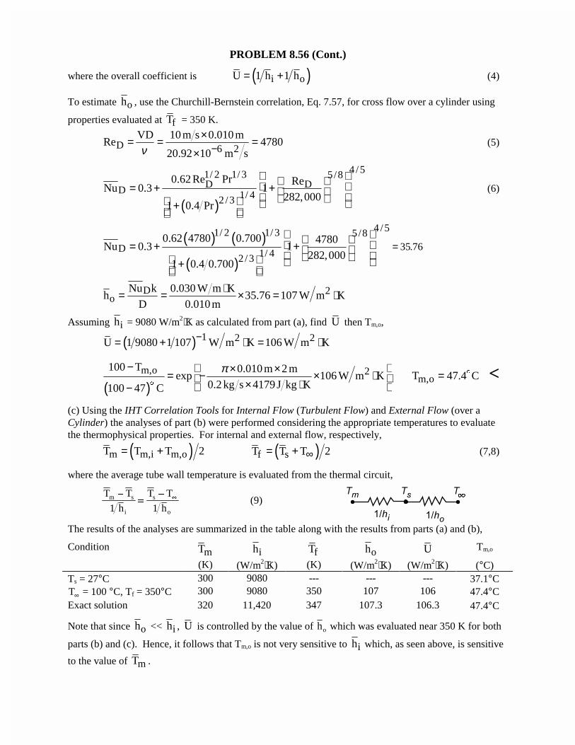
PROBLEM 8.56 (Cont.)
where the overall coefficient is ( )i oU 1 h 1 h= + (4)
To estimate oh , use the Churchill-Bernstein correlation, Eq. 7.57, for cross flow over a cylinder using
properties evaluated at fT = 350 K.
D 6 2VD 10 m s 0.010 m
Re 478020.92 10 m sν −
×= = =×
(5)
( )
4 /51/ 2 1/ 3 5/8DD
D 1/ 42 /3
0.62 Re Pr ReNu 0.3 1
282,0001 0.4 Pr
= + + +
(6)
( ) ( )
( )
4 /51/ 2 1/ 3 5/8
D 1/ 42 /3
0.62 4780 0.700 4780Nu 0.3 1
282,0001 0.4 0.700
= + + +
= 35 76.
D 2o
Nu k 0.030 W m Kh 35.76 107 W m K
D 0.010 m⋅= = × = ⋅
Assuming ih = 9080 W/m2⋅K as calculated from part (a), find U then Tm,o,
( ) 1 2 2U 1 9080 1 107 W m K 106 W m K−= + ⋅ = ⋅
( )m,o 2100 T 0.010 m 2 m
exp 106 W m K0.2 kg s 4179 J kg K100 47 C
π− × ×= − × ⋅ × ⋅ − $
m,oT 47.4 C= $ <
(c) Using the IHT Correlation Tools for Internal Flow (Turbulent Flow) and External Flow (over aCylinder) the analyses of part (b) were performed considering the appropriate temperatures to evaluatethe thermophysical properties. For internal and external flow, respectively,
( )m m,i m,oT T T 2= + ( )f sT T T 2∞= + (7,8)
where the average tube wall temperature is evaluated from the thermal circuit,
T T
h
T T
hm s
i
s
o
�
��
1 1(9)
The results of the analyses are summarized in the table along with the results from parts (a) and (b),
Condition mT ih fT oh U Tm,o
(K) (W/m2⋅K) (K) (W/m2⋅K) (W/m2⋅K) (°C)Ts = 27°C 300 9080 --- --- --- 37.1°CT∞ = 100 °C, Tf = 350°C 300 9080 350 107 106 47.4°CExact solution 320 11,420 347 107.3 106.3 47.4°C
Note that since oh << ih , U is controlled by the value of ho which was evaluated near 350 K for both
parts (b) and (c). Hence, it follows that Tm,o is not very sensitive to ih which, as seen above, is sensitive
to the value of mT .
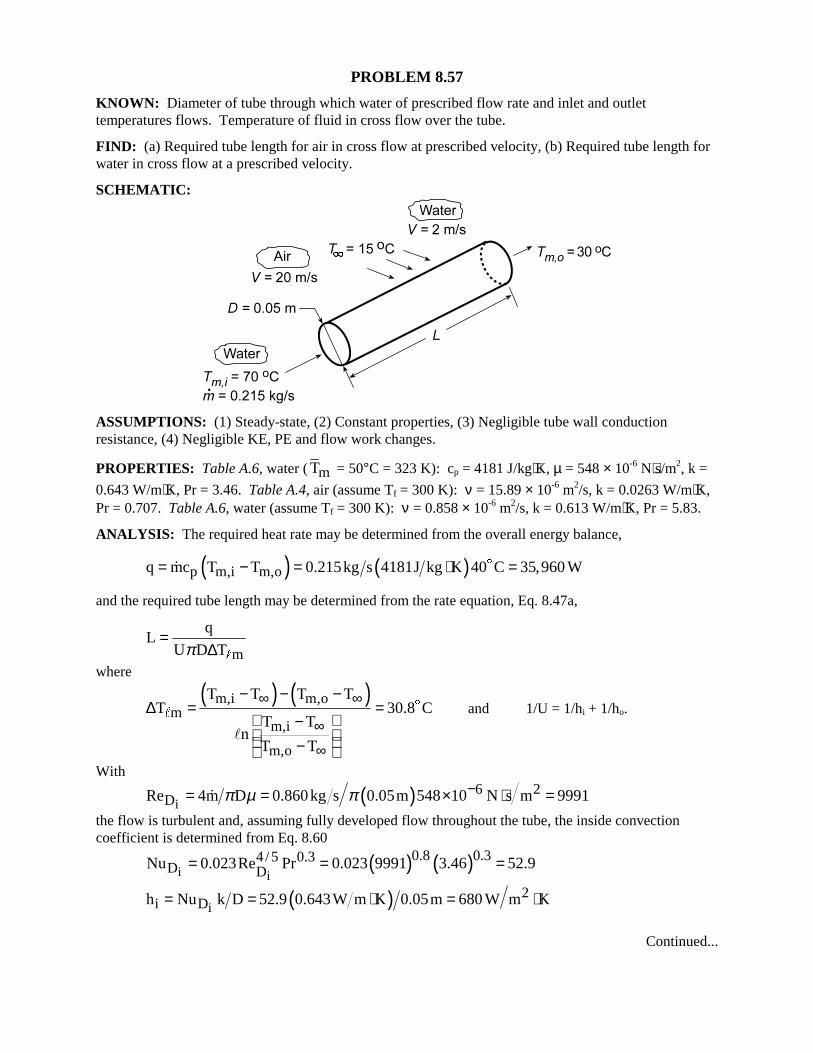
PROBLEM 8.57
KNOWN: Diameter of tube through which water of prescribed flow rate and inlet and outlettemperatures flows. Temperature of fluid in cross flow over the tube.
FIND: (a) Required tube length for air in cross flow at prescribed velocity, (b) Required tube length forwater in cross flow at a prescribed velocity.
SCHEMATIC:
ASSUMPTIONS: (1) Steady-state, (2) Constant properties, (3) Negligible tube wall conductionresistance, (4) Negligible KE, PE and flow work changes.
PROPERTIES: Table A.6, water ( mT = 50°C = 323 K): cp = 4181 J/kg⋅K, µ = 548 × 10-6 N⋅s/m2, k =
0.643 W/m⋅K, Pr = 3.46. Table A.4, air (assume Tf = 300 K): ν = 15.89 × 10⁻⁶ m2/s, k = 0.0263 W/m⋅K,Pr = 0.707. Table A.6, water (assume Tf = 300 K): ν = 0.858 × 10⁻⁶ m2/s, k = 0.613 W/m⋅K, Pr = 5.83.
ANALYSIS: The required heat rate may be determined from the overall energy balance,
( ) ( )p m,i m,oq mc T T 0.215kg s 4181J kg K 40 C 35,960 W= − = ⋅ =$�
and the required tube length may be determined from the rate equation, Eq. 8.47a,
m
qL
U D Tπ=
∆ "
where
( ) ( )m,i m,om
m,i
m,o
T T T TT 30.8 C
T Tn
T T
∞ ∞
∞
∞
− − −∆ = =
− −
$"
�
and 1/U = 1/hi + 1/ho.
With
( )i6 2
DRe 4m D 0.860kg s 0.05m 548 10 N s m 9991π µ π −= = × ⋅ =�
the flow is turbulent and, assuming fully developed flow throughout the tube, the inside convectioncoefficient is determined from Eq. 8.60
( ) ( )i i
0.8 0.34 /5 0.3D DNu 0.023Re Pr 0.023 9991 3.46 52.9= = =
( )i2
i Dh Nu k D 52.9 0.643W m K 0.05m 680 W m K= = ⋅ = ⋅
Continued...
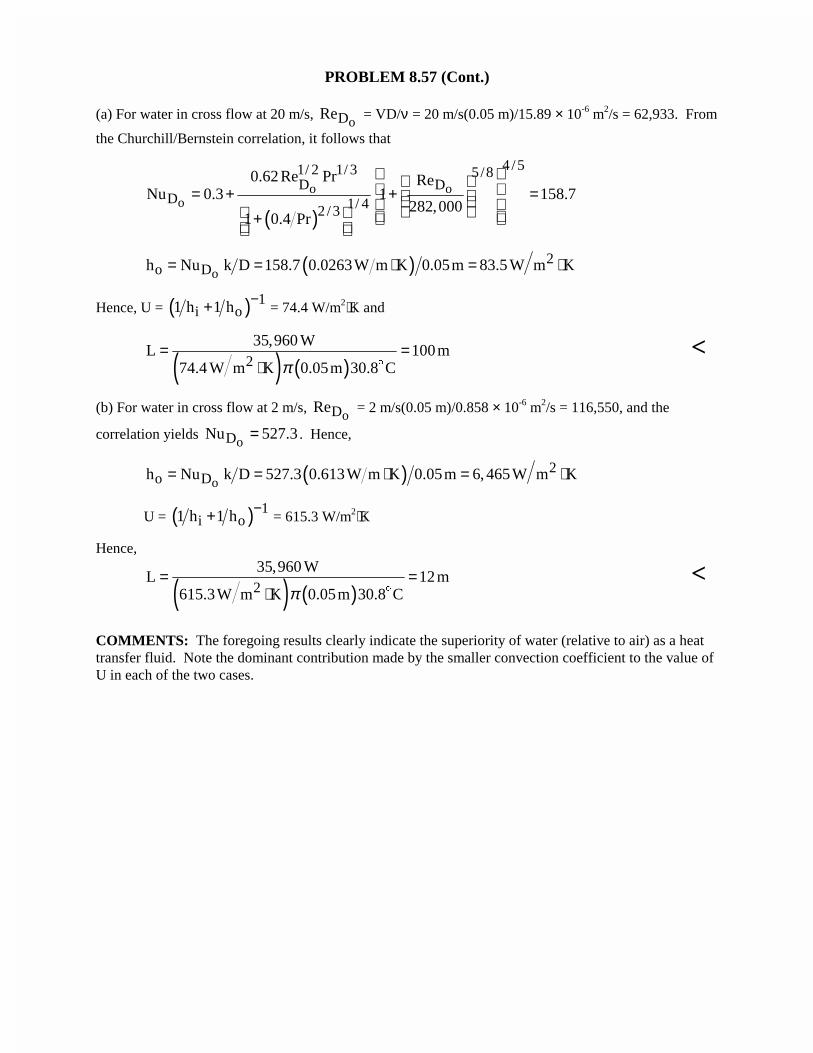
PROBLEM 8.57 (Cont.)
(a) For water in cross flow at 20 m/s, oDRe = VD/ν = 20 m/s(0.05 m)/15.89 × 10-6 m2/s = 62,933. From
the Churchill/Bernstein correlation, it follows that
( )o o
o
4 /51/ 2 1/ 3 5/8D D
D 1/ 42 /3
0.62 Re Pr ReNu 0.3 1 158.7
282,0001 0.4 Pr
= + + = +
( )o2
o Dh Nu k D 158.7 0.0263W m K 0.05m 83.5 W m K= = ⋅ = ⋅
Hence, U = ( ) 1i o1 h 1 h −+ = 74.4 W/m2⋅K and
( ) ( )2
35,960 WL 100m
74.4 W m K 0.05m 30.8 Cπ= =
⋅ $<
(b) For water in cross flow at 2 m/s, oDRe = 2 m/s(0.05 m)/0.858 × 10-6 m2/s = 116,550, and the
correlation yields oDNu 527.3= . Hence,
( )o2
o Dh Nu k D 527.3 0.613W m K 0.05m 6, 465W m K= = ⋅ = ⋅
U = ( ) 1i o1 h 1 h −+ = 615.3 W/m2⋅K
Hence,
( ) ( )2
35,960 WL 12m
615.3W m K 0.05m 30.8 Cπ= =
⋅ $<
COMMENTS: The foregoing results clearly indicate the superiority of water (relative to air) as a heattransfer fluid. Note the dominant contribution made by the smaller convection coefficient to the value ofU in each of the two cases.
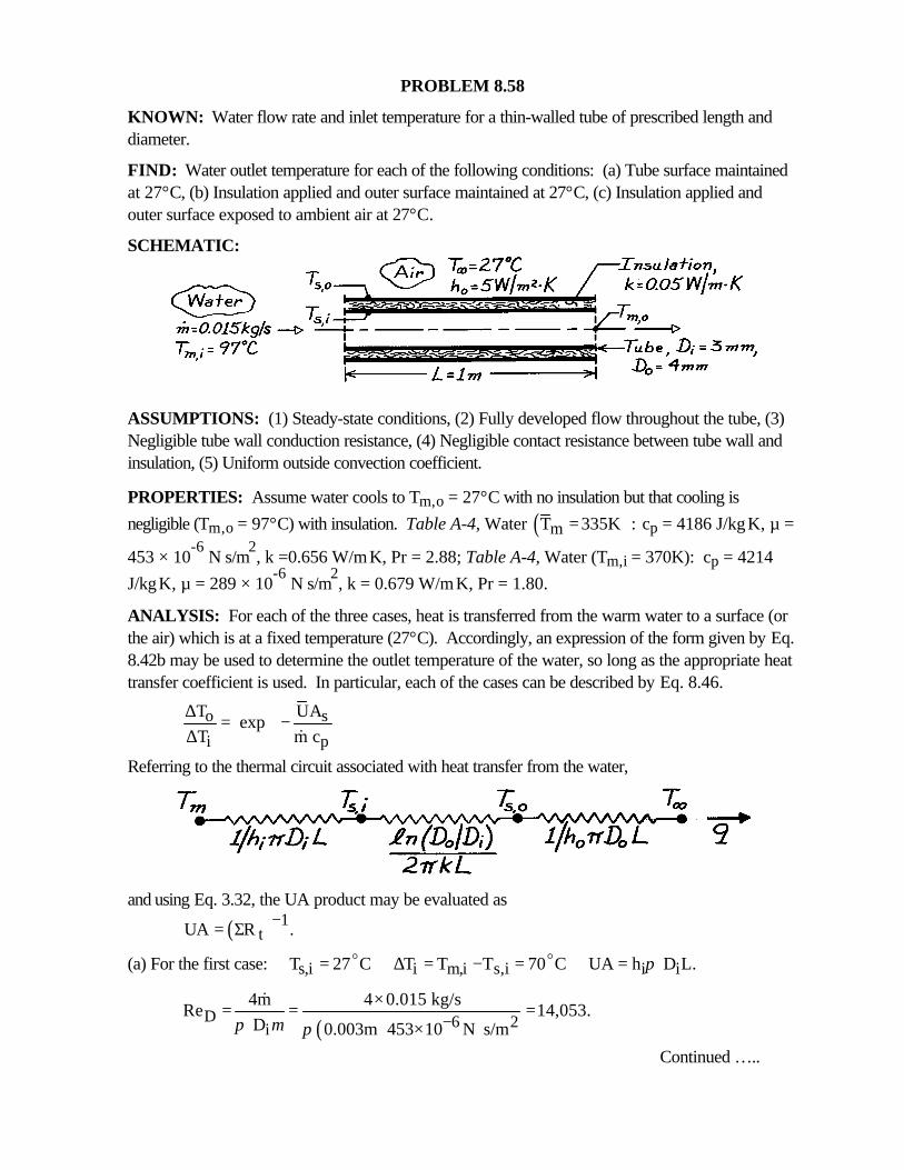
PROBLEM 8.58
KNOWN: Water flow rate and inlet temperature for a thin-walled tube of prescribed length anddiameter.
FIND: Water outlet temperature for each of the following conditions: (a) Tube surface maintainedat 27°C, (b) Insulation applied and outer surface maintained at 27°C, (c) Insulation applied andouter surface exposed to ambient air at 27°C.
SCHEMATIC:
ASSUMPTIONS: (1) Steady-state conditions, (2) Fully developed flow throughout the tube, (3)Negligible tube wall conduction resistance, (4) Negligible contact resistance between tube wall andinsulation, (5) Uniform outside convection coefficient.
PROPERTIES: Assume water cools to Tm,o = 27°C with no insulation but that cooling is
negligible (Tm,o = 97°C) with insulation. Table A-4, Water ( )mT 335K := cp = 4186 J/kg⋅K, µ =
453 × 10-6
N⋅s/m2, k =0.656 W/m⋅K, Pr = 2.88; Table A-4, Water (Tm,i = 370K): cp = 4214
J/kg⋅K, µ = 289 × 10-6
N⋅s/m2, k = 0.679 W/m⋅K, Pr = 1.80.
ANALYSIS: For each of the three cases, heat is transferred from the warm water to a surface (orthe air) which is at a fixed temperature (27°C). Accordingly, an expression of the form given by Eq.8.42b may be used to determine the outlet temperature of the water, so long as the appropriate heattransfer coefficient is used. In particular, each of the cases can be described by Eq. 8.46.
o s
i p
T UA exp
T m c
∆ = − ∆ &
Referring to the thermal circuit associated with heat transfer from the water,
and using Eq. 3.32, the UA product may be evaluated as
( ) 1tUA R .−= Σ
(a) For the first case: s,i i m,i s,i i iT 27 C T T T 70 C UA h D L.π= ∆ = − = =o o
( )D 6 2i
4m 4 0.015 kg/sRe 14,053.
D 0.003m 453 10 N s/mπ µ π −×= = =
× ⋅
&
Continued …..

PROBLEM 8.58 (Cont.)
From Eq. 8.60,
( ) ( ) ( )4 / 5 0.34/5 0.30 2i D
i
k 0.656 W/m Kh 0.023 Re Pr 0.023 14,053 2.88 14,373 W/m K.
D 0.003m
⋅= = = ⋅
2i io i
p
W14,373 0.003m 1m
h D L m KT Texp 70 C exp 8.1 Cm c 0.015 kg/s 4186 J/kg K
ππ
× × ⋅ ∆ = ∆ − = − = × ⋅
o o
&
m,o o s,iT T T 8.1 C 27 C 35.1 C.= ∆ + = + =o o o <
(b) For the second case: Ts,o = 27°C with
( ) ( ) 1i m,i s,o i i o iT T T 70 C UA 1/h D L n D / D / 2 kL .π π − ∆ = − = = +
o l
With( )D 6 2i
4 m 4 0.015 kg/sRe 22,028
D 0.003m 289 10 N s/mπ µ π −×
= = =× ⋅
&
( ) ( ) ( )4 / 5 0.34/5 0.3 2i D
i
k 0.679 W/m Kh 0.023 Re Pr 0.023 22,028 1.80 18,511 W/m K.
D 0.003m
⋅= = = ⋅
It follows that
( )( )
1 13n 0.004/0.0031UA 5.73 10 0.916 1.085 W/K
18,511 0.003 2 0.05π π
− −− = + = × + = ×
l
and the outlet temperature is
o1.085 W/K
T 70 C exp 68.8 C0.015 kg/s 4214 J/kg K
∆ = − = × ⋅
o o
m,o o s,oT T T 68.8 C 27 C 95.8 C.= ∆ + = + =o o o <
(c) For the third case: T∞ = 27°C, ∆Ti = Tm,i - T∞ = 70°C and
( ) ( ) ( ) 1i i o i o oUA 1/h D L n D / D / 2 kL 1/h D Lπ π π − = + + l
( )
1 13 31UA 5.73 10 0.916 5.73 10 0.916 15.92 0.0594 W/K
5 0.004π
− −− −= × + + = × + + =
o0.0594 W/K
T 70 C exp 69.9 C0.015 kg/s 4214 J/kg K
∆ = − = × ⋅
o o
m,o oT T T 69.9 C 27 C=96.9 C.∞= ∆ + = +o o o <COMMENTS: Note that Rconv,o >> Rcond,insul >> Rconv,i,
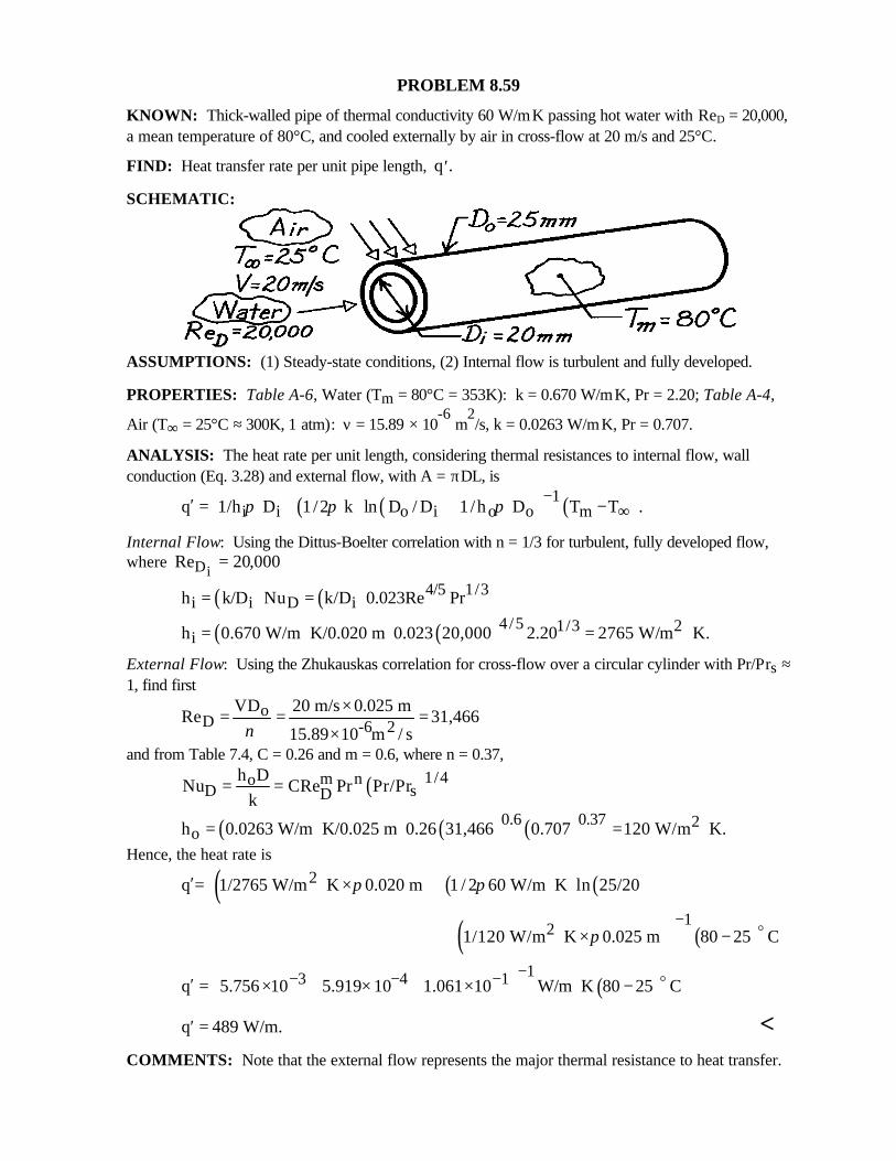
PROBLEM 8.59
KNOWN: Thick-walled pipe of thermal conductivity 60 W/m⋅K passing hot water with ReD = 20,000,a mean temperature of 80°C, and cooled externally by air in cross-flow at 20 m/s and 25°C.
FIND: Heat transfer rate per unit pipe length, ′q .
SCHEMATIC:
ASSUMPTIONS: (1) Steady-state conditions, (2) Internal flow is turbulent and fully developed.
PROPERTIES: Table A-6, Water (Tm = 80°C = 353K): k = 0.670 W/m⋅K, Pr = 2.20; Table A-4,
Air (T∞ = 25°C ≈ 300K, 1 atm): ν = 15.89 × 10⁻⁶
m2/s, k = 0.0263 W/m⋅K, Pr = 0.707.
ANALYSIS: The heat rate per unit length, considering thermal resistances to internal flow, wallconduction (Eq. 3.28) and external flow, with A = πDL, is
( ) ( ) ( )1i i o i o o mq 1/h D 1/2 k ln D / D 1/h D T T .π π π −
∞′ = + + −
Internal Flow: Using the Dittus-Boelter correlation with n = 1/3 for turbulent, fully developed flow,where ReDi
= 20 000,
( ) ( ) 4/5 1/3i i D ih k/D Nu k/D 0.023Re Pr= =
( ) ( )4/5 1/3 2ih 0.670 W/m K/0.020 m 0.023 20,000 2.20 2765 W/m K.= ⋅ = ⋅
External Flow: Using the Zhukauskas correlation for cross-flow over a circular cylinder with Pr/Prs ≈1, find first
oD -6 2
VD 20 m/s 0.025 mRe 31,466
15.89 10 m / sν×= = =
×and from Table 7.4, C = 0.26 and m = 0.6, where n = 0.37,
( )1/4m noD sD
h DNu CRe Pr Pr/Pr
k= =
( ) ( ) ( )0.6 0.37 2oh 0.0263 W/m K/0.025 m 0.26 31,466 0.707 120 W/m K.= ⋅ = ⋅
Hence, the heat rate is
( ) ( ) ( )2q = 1/2765 W/m K 0.020 m 1 / 2 60 W/m K ln 25/20π π′ ⋅ × + ⋅
( ) ( )1
21/120 W/m K 0.025 m 80 25 Cπ−+ ⋅ × −
o
( )13 4 1q 5.756 10 5.919 10 1.061 10 W/m K 80 25 C
−− − − ′ = × + × + × ⋅ − o
q 489 W/m.′ = <COMMENTS: Note that the external flow represents the major thermal resistance to heat transfer.
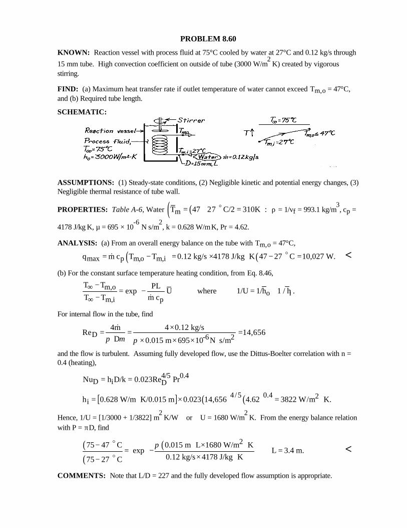
PROBLEM 8.60
KNOWN: Reaction vessel with process fluid at 75°C cooled by water at 27°C and 0.12 kg/s through
15 mm tube. High convection coefficient on outside of tube (3000 W/m2⋅K) created by vigorous
stirring.
FIND: (a) Maximum heat transfer rate if outlet temperature of water cannot exceed Tm,o = 47°C,and (b) Required tube length.
SCHEMATIC:
ASSUMPTIONS: (1) Steady-state conditions, (2) Negligible kinetic and potential energy changes, (3)Negligible thermal resistance of tube wall.
PROPERTIES: Table A-6, Water ( )( )mT 47 27 C/2 310K := + =o ρ = 1/vf = 993.1 kg/m3, cp =
4178 J/kg⋅K, µ = 695 × 10-6
N⋅s/m2, k = 0.628 W/m⋅K, Pr = 4.62.
ANALYSIS: (a) From an overall energy balance on the tube with Tm,o = 47°C,
( ) ( )max p m,o m,iq m c T T 0.12 kg/s 4178 J/kg K 47 27 C 10,027 W.= − = × ⋅ − =o& <(b) For the constant surface temperature heating condition, from Eq. 8.46,
m,oo i
m,i p
T T PLexp U where 1/U 1/h 1 / h .
T T m c∞
∞
−= − = + − &
For internal flow in the tube, find
D -6 24m 4 0.12 kg/s
Re 14,656 D 0.015 m 695 10 N s/mπ µ π
×= = =× × × ⋅
&
and the flow is turbulent. Assuming fully developed flow, use the Dittus-Boelter correlation with n =0.4 (heating),
4/5 0.4D i DNu h D/k 0.023Re Pr= =
[ ] ( ) ( )4/5 0.4 2ih 0.628 W/m K/0.015 m 0.023 14,656 4.62 3822 W/m K.= ⋅ × = ⋅
Hence, 1/U = [1/3000 + 1/3822] m2⋅K/W or U = 1680 W/m
2⋅K. From the energy balance relation
with P = πD, find
( )( )
( ) 275 47 C 0.015 m L 1680 W/m K exp L 3.4 m.
0.12 kg/s 4178 J/kg K75 27 C
π − × ⋅ = − = × ⋅−
o
o<
COMMENTS: Note that L/D = 227 and the fully developed flow assumption is appropriate.
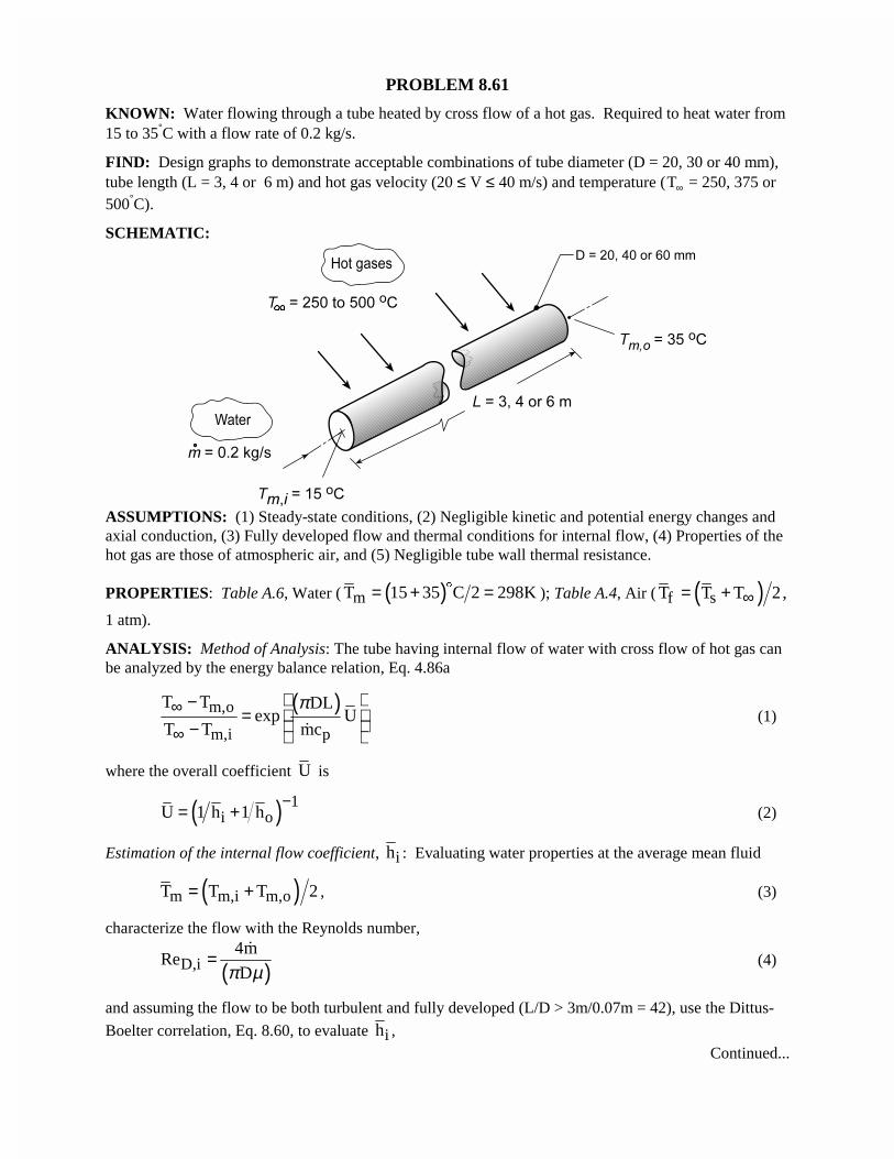
PROBLEM 8.61
KNOWN: Water flowing through a tube heated by cross flow of a hot gas. Required to heat water from15 to 35°C with a flow rate of 0.2 kg/s.
FIND: Design graphs to demonstrate acceptable combinations of tube diameter (D = 20, 30 or 40 mm),tube length (L = 3, 4 or 6 m) and hot gas velocity (20 ≤ V ≤ 40 m/s) and temperature (T∞ = 250, 375 or500°C).
SCHEMATIC:
ASSUMPTIONS: (1) Steady-state conditions, (2) Negligible kinetic and potential energy changes andaxial conduction, (3) Fully developed flow and thermal conditions for internal flow, (4) Properties of thehot gas are those of atmospheric air, and (5) Negligible tube wall thermal resistance.
PROPERTIES: Table A.6, Water ( ( )mT 15 35 C 2 298K= + =$
); Table A.4, Air ( ( )f sT T T 2,∞= +1 atm).
ANALYSIS: Method of Analysis: The tube having internal flow of water with cross flow of hot gas canbe analyzed by the energy balance relation, Eq. 4.86a
( )m,o
m,i p
T T DLexp U
T T mc
π∞
∞
−= − �
(1)
where the overall coefficient U is
( ) 1i oU 1 h 1 h
−= + (2)
Estimation of the internal flow coefficient, ih : Evaluating water properties at the average mean fluid
( )m m,i m,oT T T 2= + , (3)
characterize the flow with the Reynolds number,
( )D,i4m
ReDπ µ
=�
(4)
and assuming the flow to be both turbulent and fully developed (L/D > 3m/0.07m = 42), use the Dittus-
Boelter correlation, Eq. 8.60, to evaluate ih ,Continued...
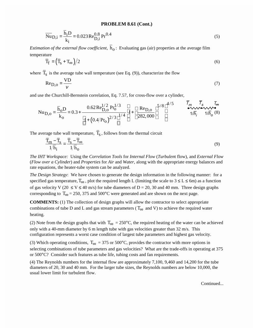
PROBLEM 8.61 (Cont.)
0.8 0.4iD,i D,i
i
h DNu 0.023Re Pr
k= = (5)
Estimation of the external flow coefficient, oh : Evaluating gas (air) properties at the average film
temperature
( )f sT T T 2∞= + (6)
where sT is the average tube wall temperature (see Eq. (9)), characterize the flow
D,oVD
Reν
= (7)
and use the Churchill-Bernstein correlation, Eq. 7.57, for cross-flow over a cylinder,
( )
4 /51/ 2 1/3 5/8oD,o D,oo
D,o 1/ 4o 2 / 3o
0.62Re Pr Reh DNu 0.3 1
k 282,0001 0.4 Pr
= = + + +
(8)
The average tube wall temperature, sT , follows from the thermal circuit
m s s
i o
T T T T
1 h 1 h∞− −= (9)
The IHT Workspace: Using the Correlation Tools for Internal Flow (Turbulent flow), and External Flow(Flow over a Cylinder) and Properties for Air and Water, along with the appropriate energy balances andrate equations, the heater-tube system can be analyzed.
The Design Strategy: We have chosen to generate the design information in the following manner: for aspecified gas temperature, T∞ , plot the required length L (limiting the scale to 3 ≤ L ≤ 6m) as a function
of gas velocity V (20 ≤ V ≤ 40 m/s) for tube diameters of D = 20, 30 and 40 mm. Three design graphscorresponding to T∞ = 250, 375 and 500°C were generated and are shown on the next page.
COMMENTS: (1) The collection of design graphs will allow the contractor to select appropriatecombinations of tube D and L and gas stream parameters ( T∞ and V) to achieve the required waterheating.
(2) Note from the design graphs that with T∞ = 250°C, the required heating of the water can be achievedonly with a 40-mm diameter by 6 m length tube with gas velocities greater than 32 m/s. Thisconfiguration represents a worst case condition of largest tube parameters and highest gas velocity.
(3) Which operating conditions, T∞ = 375 or 500°C, provides the contractor with more options inselecting combinations of tube parameters and gas velocities? What are the trade-offs in operating at 375or 500°C? Consider such features as tube life, tubing costs and fan requirements.
(4) The Reynolds numbers for the internal flow are approximately 7,100, 9,460 and 14,200 for the tubediameters of 20, 30 and 40 mm. For the larger tube sizes, the Reynolds numbers are below 10,000, theusual lower limit for turbulent flow.
Continued...
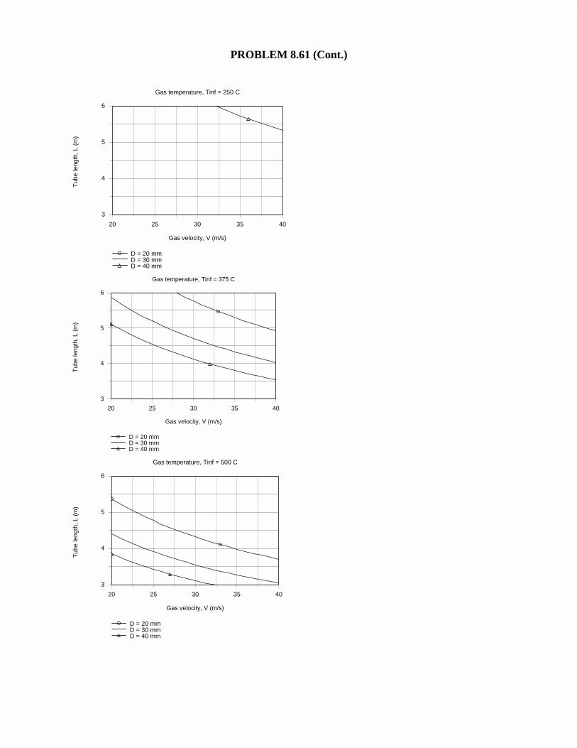
PROBLEM 8.61 (Cont.)
Gas temperature, Tinf = 250 C
20 25 30 35 40
Gas velocity, V (m/s)
3
4
5
6
Tub
e le
ngth
, L (
m)
D = 20 mmD = 30 mmD = 40 mm
Gas temperature, Tinf = 375 C
20 25 30 35 40
Gas velocity, V (m/s)
3
4
5
6
Tub
e le
ngth
, L (
m)
D = 20 mmD = 30 mmD = 40 mm
Gas temperature, Tinf = 500 C
20 25 30 35 40
Gas velocity, V (m/s)
3
4
5
6
Tub
e le
ngth
, L (
m)
D = 20 mmD = 30 mmD = 40 mm
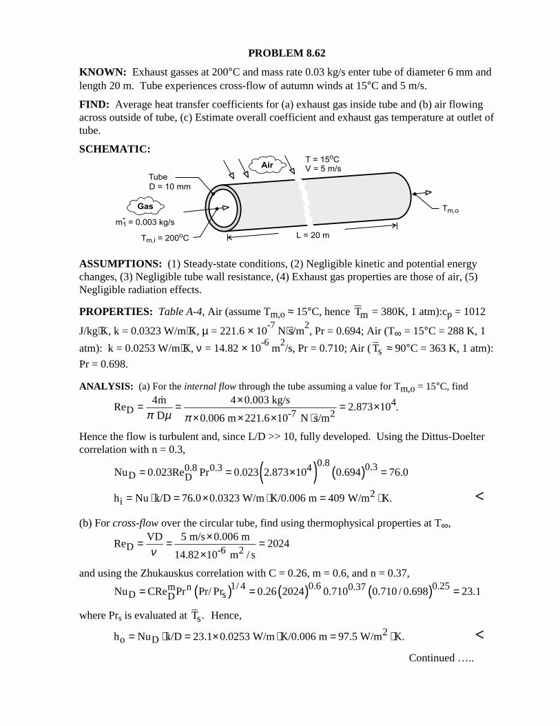
PROBLEM 8.62
KNOWN: Exhaust gasses at 200°C and mass rate 0.03 kg/s enter tube of diameter 6 mm andlength 20 m. Tube experiences cross-flow of autumn winds at 15°C and 5 m/s.
FIND: Average heat transfer coefficients for (a) exhaust gas inside tube and (b) air flowingacross outside of tube, (c) Estimate overall coefficient and exhaust gas temperature at outlet oftube.
SCHEMATIC:
ASSUMPTIONS: (1) Steady-state conditions, (2) Negligible kinetic and potential energychanges, (3) Negligible tube wall resistance, (4) Exhaust gas properties are those of air, (5)Negligible radiation effects.
PROPERTIES: Table A-4, Air (assume Tm,o ≈ 15°C, hence Tm = 380K, 1 atm):cp = 1012
J/kg⋅K, k = 0.0323 W/m⋅K, µ = 221.6 × 10⁻⁷
N⋅s/m2, Pr = 0.694; Air (T∞ = 15°C = 288 K, 1
atm): k = 0.0253 W/m⋅K, ν = 14.82 × 10⁻⁶
m2/s, Pr = 0.710; Air ( sT ≈ 90°C = 363 K, 1 atm):
Pr = 0.698.
ANALYSIS: (a) For the internal flow through the tube assuming a value for Tm,o = 15°C, find
4D -7 2
4m 4 0.003 kg/sRe 2.873 10 .
D 0.006 m 221.6 10 N s/mπ µ π×= = = ×
× × × ⋅
�
Hence the flow is turbulent and, since L/D >> 10, fully developed. Using the Dittus-Doeltercorrelation with n = 0.3,
( ) ( )0.8 0.30.8 0.3 4
D DNu 0.023Re Pr 0.023 2.873 10 0.694 76.0= = × =
2ih Nu k/D 76.0 0.0323 W/m K/0.006 m 409 W/m K.= ⋅ = × ⋅ = ⋅ <
(b) For cross-flow over the circular tube, find using thermophysical properties at T∞,
D -6 2VD 5 m/s 0.006 m
Re 202414.82 10 m / sν
×= = =×
and using the Zhukauskus correlation with C = 0.26, m = 0.6, and n = 0.37,
( ) ( ) ( )1/ 4 0.6 0.25m n 0.37D sDNu CRe Pr Pr/ Pr 0.26 2024 0.710 0.710 / 0.698 23.1= = =
where Prs is evaluated at sT . Hence,
2o Dh Nu k/D 23.1 0.0253 W/m K/0.006 m 97.5 W/m K.= ⋅ = × ⋅ = ⋅ <
Continued …..
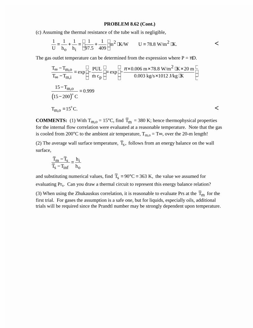
PROBLEM 8.62 (Cont.)
(c) Assuming the thermal resistance of the tube wall is negligible,
2 2
o i
1 1 1 1 1m K/W U 78.8 W/m K.
U h h 97.5 409 = + = + ⋅ = ⋅
<
The gas outlet temperature can be determined from the expression where P = πD.
2m,o
m,i p
T T PUL 0.006 m 78.8 W/m K 20 mexp exp
T T m c 0.003 kg/s 1012 J/kg K
π∞
∞
− × × ⋅ × = − = − − × ⋅ �
( )m,o15 T
0.99915 200 C
−=
− $
m,oT 15 C.= $ <
COMMENTS: (1) With Tm,o = 15°C, find mT = 380 K; hence thermophysical propertiesfor the internal flow correlation were evaluated at a reasonable temperature. Note that the gasis cooled from 200°C to the ambient air temperature, Tm,o = T∞, over the 20-m length!
(2) The average wall surface temperature, sT , follows from an energy balance on the wall
surface,
m s i
s inf o
T T h
T T h
− =−
and substituting numerical values, find sT 90 C 363 K,= ° = the value we assumed for
evaluating Prs. Can you draw a thermal circuit to represent this energy balance relation?
(3) When using the Zhukauskus correlation, it is reasonable to evaluate Prs at the mT for thefirst trial. For gases the assumption is a safe one, but for liquids, especially oils, additionaltrials will be required since the Prandtl number may be strongly dependent upon temperature.
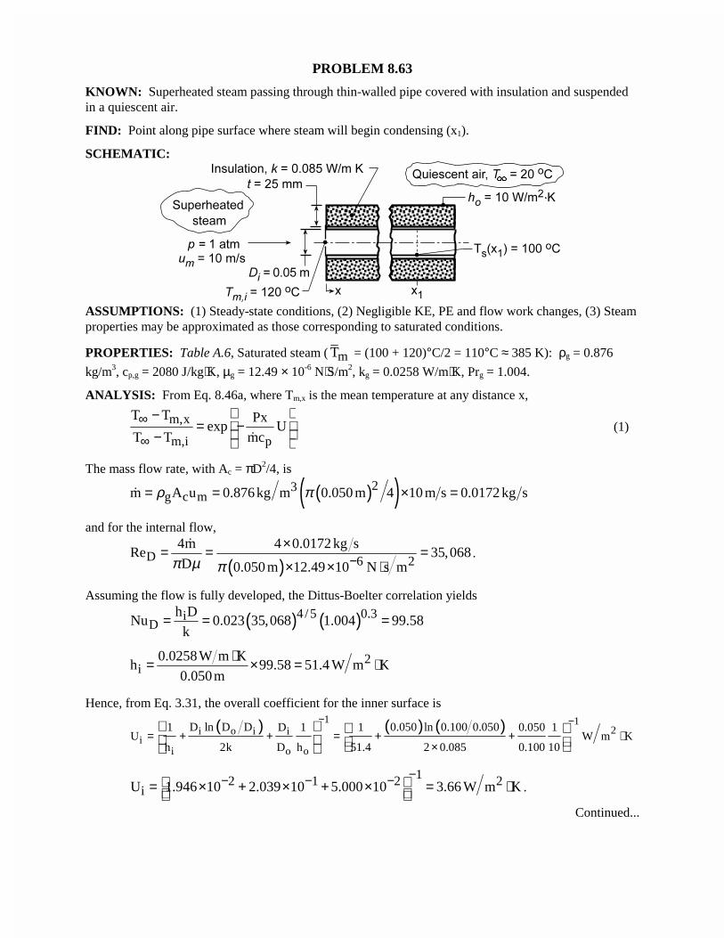
PROBLEM 8.63
KNOWN: Superheated steam passing through thin-walled pipe covered with insulation and suspendedin a quiescent air.
FIND: Point along pipe surface where steam will begin condensing (x1).
SCHEMATIC:
ASSUMPTIONS: (1) Steady-state conditions, (2) Negligible KE, PE and flow work changes, (3) Steamproperties may be approximated as those corresponding to saturated conditions.
PROPERTIES: Table A.6, Saturated steam ( mT = (100 + 120)°C/2 = 110°C ≈ 385 K): ρg = 0.876
kg/m3, cp,g = 2080 J/kg⋅K, µg = 12.49 × 10⁻⁶ N⋅S/m2, kg = 0.0258 W/m⋅K, Prg = 1.004.
ANALYSIS: From Eq. 8.46a, where Tm,x is the mean temperature at any distance x,
m,x
m,i p
T T Pxexp U
T T mc∞
∞
−= − − �
(1)
The mass flow rate, with Ac = πD2/4, is
( )( )23g c mm A u 0.876kg m 0.050 m 4 10 m s 0.0172 kg sρ π= = × =�
and for the internal flow,
( )D 6 24m 4 0.0172 kg s
Re 35,068D 0.050 m 12.49 10 N s mπ µ π −
×= = =× × ⋅
�.
Assuming the flow is fully developed, the Dittus-Boelter correlation yields
( ) ( )4 /5 0.3iD
h DNu 0.023 35,068 1.004 99.58
k= = =
2i
0.0258W m Kh 99.58 51.4 W m K
0.050m
⋅= × = ⋅
Hence, from Eq. 3.31, the overall coefficient for the inner surface is
( ) ( ) ( )1 12i o i i
ii o o
D ln D D 0.050 ln 0.100 0.0501 D 1 1 0.050 1U W m K
h 2k D h 51.4 2 0.085 0.100 10
− −= + + = + + ⋅
×
12 1 2 2iU 1.946 10 2.039 10 5.000 10 3.66 W m K
−− − − = × + × + × = ⋅ .
Continued...
PROBLEM 8.63 (Cont.)
With condensation occurring when the surface temperature reaches 100°C, the corresponding value of Tm
may be determined from the local (x = x1) requirement that ( ) ( )i i m 1U D T x Tπ ∞ − = ( ) ( )i i m 1 sh D T x Tπ − . Hence,
( ) ( )( )
( )( )
i i sm 1
i i
T h U T 20 51.4 3.66 100 CT x 107.7 C
1 h U 1 51.4 3.66∞ − −
= = =− −
$
$
The distance at which the mean steam temperature is 107.7°C can then be estimated from Eq. (1), whereP = πDi and U = Ui,
( )( )
( ) ( )2120 107.7 C 0.050m 3.66 W m K x
exp0.0172 kg s 2080 J kg K20 120 C
π − ⋅ = − × ⋅−
$
$
x1 = 8.15 m <COMMENTS: Note that condensation first occurs at the location for which the surface, and not themean, temperature reaches 100°C.
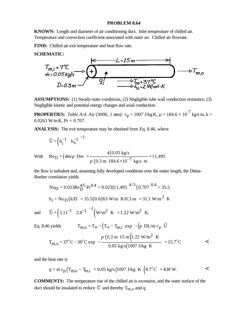
PROBLEM 8.64
KNOWN: Length and diameter of air conditioning duct. Inlet temperature of chilled air.Temperature and convection coefficient associated with outer air. Chilled air flowrate.
FIND: Chilled air exit temperature and heat flow rate.
SCHEMATIC:
ASSUMPTIONS: (1) Steady-state conditions, (2) Negligible tube wall conduction resistance, (3)Negligible kinetic and potential energy changes and axial conduction.
PROPERTIES: Table A-4, Air (300K, 1 atm): cp = 1007 J/kg⋅K, µ = 184.6 × 10⁻⁷
kg/s⋅m, k =0.0263 W/m⋅K, Pr = 0.707.
ANALYSIS: The exit temperature may be obtained from Eq. 8.46, where
( ) 11 1oiU h h
−− −= +
With ( ) ( )( )D 7
4 0.05 kg/sRe 4m/ D 11,495
0.3 m 184.6 10 kg/s mπ µ
π −= = =× ⋅
&
the flow is turbulent and, assuming fully developed conditions over the entire length, the Dittus-Boelter correlation yields
( ) ( )4/5 0.44/5 0.4D DNu 0.023Re Pr 0.023 11,495 0.707 35.5= = =
( ) ( ) 2i Dh Nu k/D 35.5 0.0263 W/m K/0.3 m 31.1 W/m K= = ⋅ = ⋅
and ( ) ( )11 1 2 2U 3.11 2.0 W/m K 1.22 W/m K.−− −= + ⋅ = ⋅
Eq. 8.46 yields ( ) ( )m,o m,i pT T T T exp DL/m c Uπ∞ ∞ = − − − &
( ) ( )( )
2
m,o0.3 m 15 m 1.22 W/m K
T 37 C 30 C exp 15.7 C0.05 kg/s 1007 J/kg K
π ⋅ = − − = ⋅
o o o <
and the heat rate is
( ) ( )( )p m,o m,iq m c T T 0.05 kg/s 1007 J/kg K 8.7 C 438 W.= − = ⋅ =o& <
COMMENTS: The temperature rise of the chilled air is excessive, and the outer surface of theduct should be insulated to reduce U and thereby Tm,o and q.
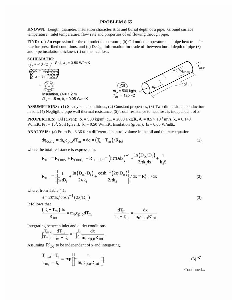
PROBLEM 8.65
KNOWN: Length, diameter, insulation characteristics and burial depth of a pipe. Ground surfacetemperature. Inlet temperature, flow rate and properties of oil flowing through pipe.
FIND: (a) An expression for the oil outlet temperature, (b) Oil outlet temperature and pipe heat transferrate for prescribed conditions, and (c) Design information for trade off between burial depth of pipe (z)and pipe insulation thickness (t) on the heat loss.
SCHEMATIC:
ASSUMPTIONS: (1) Steady-state conditions, (2) Constant properties, (3) Two-dimensional conductionin soil, (4) Negligible pipe wall thermal resistance, (5) Total resistance to heat loss is independent of x.
PROPERTIES: Oil (given): ρo = 900 kg/m3, cp,o = 2000 J/kg⋅K, νo = 8.5 × 10⁻⁴ m2/s, ko = 0.140W/m⋅K, Pro = 104; Soil (given): ks = 0.50 W/m⋅K; Insulation (given): ki = 0.05 W/m⋅K.
ANALYSIS: (a) From Eq. 8.36 for a differential control volume in the oil and the rate equation
( )conv o p,o m s m totdq m c dT dq T T R= = = −� (1)
where the total resistance is expressed as
( ) ( )1 o itot conv cond,i cond,s
i s
ln D D 1R R R R h Ddx
2 k dx k Sπ
π−
= + + = + +
( ) ( )1o i o
tot toti i s
ln D D cosh 2z D1R / dx R dx
h D 2 k 2 kπ π π
− ′= + + =
(2)
where, from Table 4.1,
( )1oS 2 dx cosh 2z Dπ −= (3)
It follows that
( )s mo p,o m
tot
T T dxm c dT
R
−=
′� m
s m o p,o tot
dT dx
T T m c R=
′− �
Integrating between inlet and outlet conditions
m,o
m,i
T LmT 0m s o p,o tot
dT dx
T T m c R= −
′−∫ ∫�
.
Assuming totR′ to be independent of x and integrating,
m,o s
m,i s o p,o tot
T T Lexp
T T m c R
−= − ′− �
. (3) <Continued...
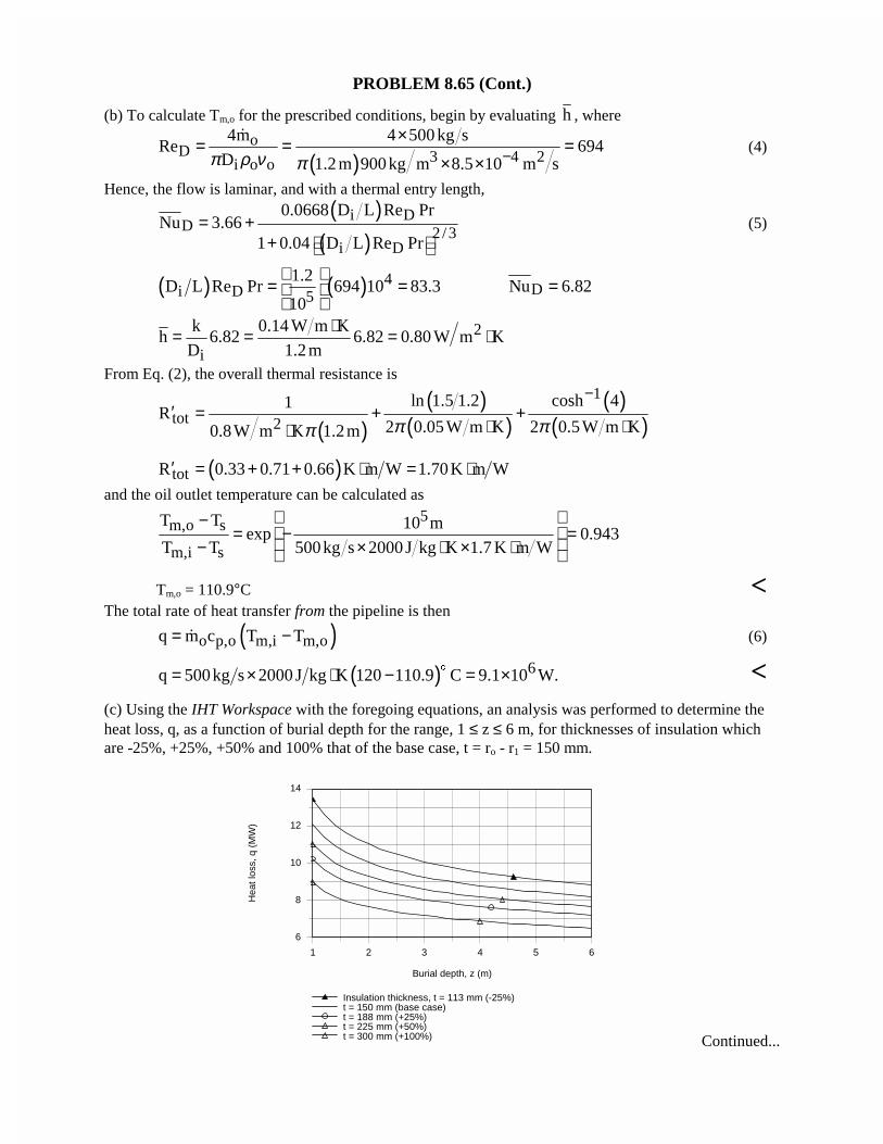
PROBLEM 8.65 (Cont.)
(b) To calculate Tm,o for the prescribed conditions, begin by evaluating h , where
( )o
D 3 4 2i o o
4m 4 500 kg sRe 694
D 1.2 m 900kg m 8.5 10 m sπ ρ ν π −×= = =
× ×
�(4)
Hence, the flow is laminar, and with a thermal entry length,
( )( )
i DD 2/3
i D
0.0668 D L Re PrNu 3.66
1 0.04 D L Re Pr= +
+ (5)
( ) ( ) 4Di D 5
1.2D L Re Pr 694 10 83.3 Nu 6.82
10
= = =
2
i
k 0.14 W m Kh 6.82 6.82 0.80 W m K
D 1.2 m
⋅= = = ⋅
From Eq. (2), the overall thermal resistance is
( )( )
( )( )
( )1
tot 2
ln 1.5 1.2 cosh 41R
2 0.05W m K 2 0.5W m K0.8W m K 1.2m π ππ
−′ = + +
⋅ ⋅⋅
( )totR 0.33 0.71 0.66 K m W 1.70K m W′ = + + ⋅ = ⋅and the oil outlet temperature can be calculated as
5m,o s
m,i s
T T 10 mexp 0.943
T T 500kg s 2000 J kg K 1.7 K m W
− = − = − × ⋅ × ⋅
Tm,o = 110.9°C <The total rate of heat transfer from the pipeline is then
( )o p,o m,i m,oq m c T T= −� (6)
( ) 6q 500kg s 2000 J kg K 120 110.9 C 9.1 10 W.= × ⋅ − = ×$ <(c) Using the IHT Workspace with the foregoing equations, an analysis was performed to determine theheat loss, q, as a function of burial depth for the range, 1 ≤ z ≤ 6 m, for thicknesses of insulation whichare -25%, +25%, +50% and 100% that of the base case, t = ro - r1 = 150 mm.
1 2 3 4 5 6
Burial depth, z (m)
6
8
10
12
14
Hea
t los
s, q
(M
W)
Insulation thickness, t = 113 mm (-25%)t = 150 mm (base case)t = 188 mm (+25%)t = 225 mm (+50%)t = 300 mm (+100%) Continued...
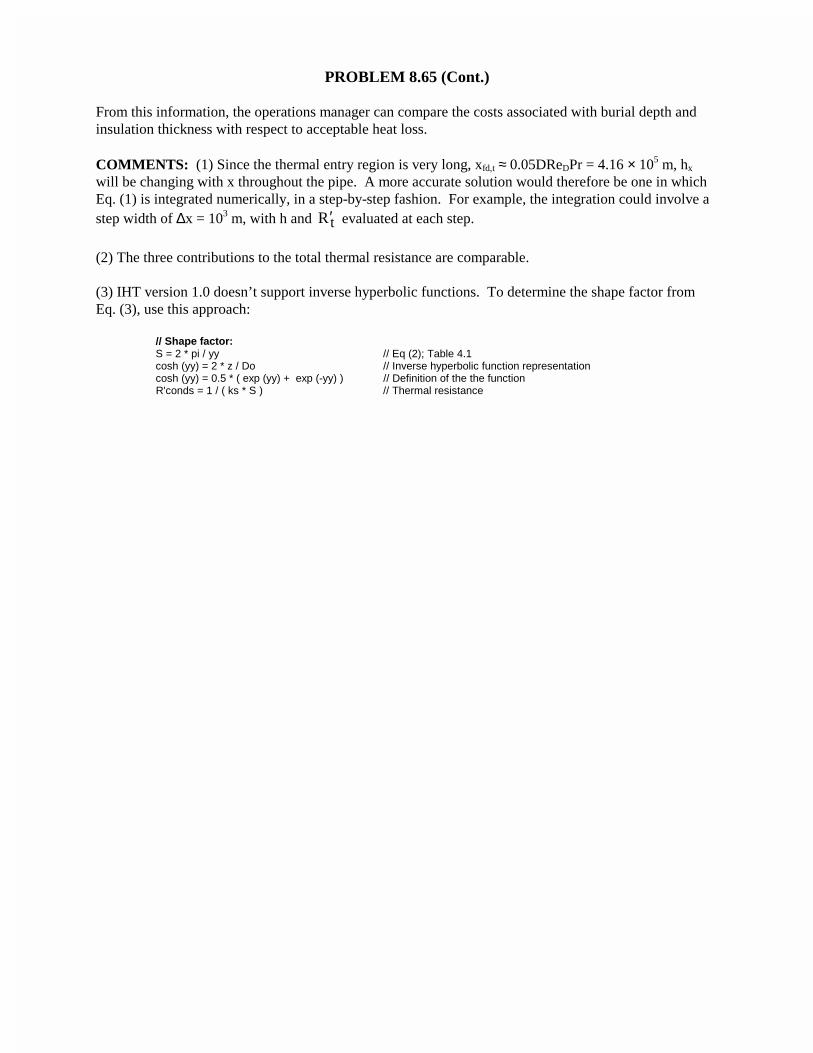
PROBLEM 8.65 (Cont.)
From this information, the operations manager can compare the costs associated with burial depth andinsulation thickness with respect to acceptable heat loss.
COMMENTS: (1) Since the thermal entry region is very long, xfd,t ≈ 0.05DReDPr = 4.16 × 10⁵ m, hx
will be changing with x throughout the pipe. A more accurate solution would therefore be one in whichEq. (1) is integrated numerically, in a step-by-step fashion. For example, the integration could involve astep width of ∆x = 103 m, with h and tR′ evaluated at each step.
(2) The three contributions to the total thermal resistance are comparable.
(3) IHT version 1.0 doesn’t support inverse hyperbolic functions. To determine the shape factor fromEq. (3), use this approach:
// Shape factor:S = 2 * pi / yy // Eq (2); Table 4.1cosh (yy) = 2 * z / Do // Inverse hyperbolic function representationcosh (yy) = 0.5 * ( exp (yy) + exp (-yy) ) // Definition of the the function
R'conds = 1 / ( ks * S ) // Thermal resistance
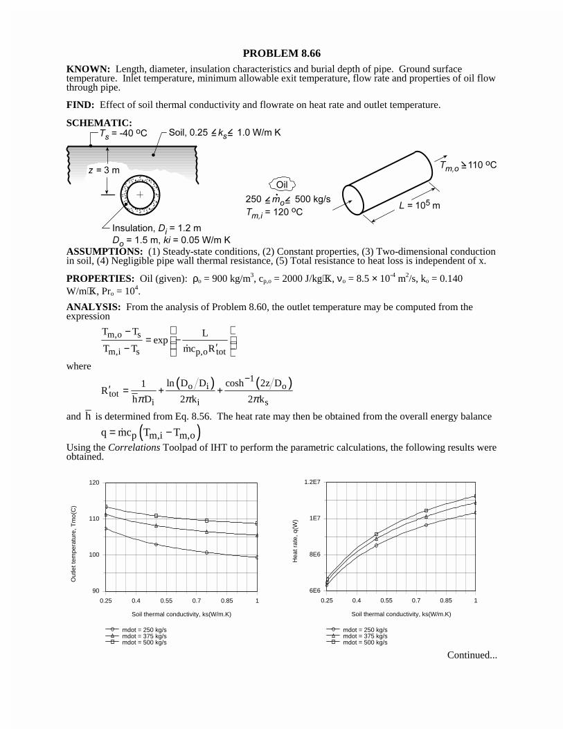
PROBLEM 8.66KNOWN: Length, diameter, insulation characteristics and burial depth of pipe. Ground surfacetemperature. Inlet temperature, minimum allowable exit temperature, flow rate and properties of oil flowthrough pipe.
FIND: Effect of soil thermal conductivity and flowrate on heat rate and outlet temperature.
SCHEMATIC:
ASSUMPTIONS: (1) Steady-state conditions, (2) Constant properties, (3) Two-dimensional conductionin soil, (4) Negligible pipe wall thermal resistance, (5) Total resistance to heat loss is independent of x.
PROPERTIES: Oil (given): ρo = 900 kg/m3, cp,o = 2000 J/kg⋅K, νo = 8.5 × 10⁻⁴ m2/s, ko = 0.140W/m⋅K, Pro = 104.
ANALYSIS: From the analysis of Problem 8.60, the outlet temperature may be computed from theexpression
m,o s
m,i s p,o tot
T T Lexp
T T mc R
−= −
′−
�
where
( ) ( )1o i o
toti i s
ln D D cosh 2z D1R
h D 2 k 2 kπ π π
−′ = + +
and h is determined from Eq. 8.56. The heat rate may then be obtained from the overall energy balance
( )p m,i m,oq mc T T= −�
Using the Correlations Toolpad of IHT to perform the parametric calculations, the following results wereobtained.
0.25 0.4 0.55 0.7 0.85 1
Soil thermal conductivity, ks(W/m.K)
90
100
110
120
Out
let t
empe
ratu
re, T
mo(
C)
mdot = 250 kg/smdot = 375 kg/smdot = 500 kg/s
0.25 0.4 0.55 0.7 0.85 1
Soil thermal conductivity, ks(W/m.K)
6E6
8E6
1E7
1.2E7
Hea
t rat
e, q
(W)
mdot = 250 kg/smdot = 375 kg/smdot = 500 kg/s
Continued...
PROBLEM 8.66 (Cont.)
Due to a reduction in the thermal conduction resistance of the soil with increasing ks, there is acorresponding increase in the heat rate q from the pipe and a reduction in the oil outlet temperature. The
heat rate also increases with increasing m� (due to an increase in h and hence a decrease in theconvection resistance), but the increase lags that of the flow rate, causing the outlet temperature toincrease with increasing �m . Conditions for which Tm,o ≥ 110°C cannot be achieved for �m = 250 kg/s,but can be achieved for ks ≤ 0.33 W/m⋅K and ks ≤ 0.65 W/m⋅K for �m = 375 kg/s and 500 kg/s,respectively. The worst case condition corresponds to the smallest value of �m and the largest value of ks.
Measures to maintain Tm,o ≥ 110°C could include increasing the burial depth, increasing the insulationthickness, and/or using an insulation of lower thermal conductivity.
COMMENTS: The thermophysical properties of oil depend strongly on temperature, and a more
accurate solution would account for the effect of variations in mT on the properties.
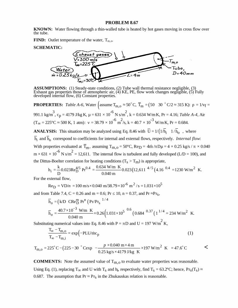
PROBLEM 8.67KNOWN: Water flowing through a thin-walled tube is heated by hot gases moving in cross flow overthe tube.
FIND: Outlet temperature of the water, Tm,o.
SCHEMATIC:
ASSUMPTIONS: (1) Steady-state conditions, (2) Tube wall thermal resistance negligible, (3)Exhaust gas properties those of atmospheric air, (4) KE, PE, flow work changes negligible, (5) Fullydeveloped internal flow, (6) Constant properties.
PROPERTIES: Table A-6, Water ( ( )m,o massume T 50 C, T 50 30 C/2 315 K):≈ = + ≈oo ρ = 1/vf =
991.1 kg/m3, cp = 4179 J/kg⋅K, µ = 631 × 10
-6 N⋅s/m
2, k = 0.634 W/m⋅K, Pr = 4.16; Table A-4, Air
(T∞ = 225°C ≈ 500 K, 1 atm): ν = 38.79 × 10⁻⁶
m2/s, k = 40.7 × 10
-3 W/m⋅K, Pr = 0.684.
ANALYSIS: This situation may be analyzed using Eq. 8.46 with ( )i oU 1/ 1/h 1 / h ,= + where
i oh and h correspond to coefficients for internal and external flows, respectively. Internal flow:
With properties evaluated at mT , assuming Tm,o = 50°C, ReD = 4m& /πDµ = 4 × 0.25 kg/s / π × 0.040
m × 631 × 10-6
N⋅s/m2 = 12,611. The internal flow is turbulent and fully developed (L/D = 100), and
the Dittus-Boelter correlation for heating conditions (Ts > Tm) is appropriate,
( ) ( )4 / 5 0.44/5 0.4 2i D
k 0.634 W/m Kh 0.023Re Pr 0.023 12,611 4.16 1230 W/m K.
D 0.040 m
⋅= = = ⋅
For the external flow,-6 2 5
DRe VD/ 100 m/s 0.040 m/38.79 10 m /s 1.031 10ν= = × × = ×
and from Table 7.4, C = 0.26 and m = 0.6; Pr ≤ 10, n = 0.37, and Pr ≈Prs,
( ) ( )1 / 4m no D sh k/D CRe Pr Pr/Pr=
( ) ( ) ( )3 0.6 0.37 1 / 45 2
o40.7 10 W/m K
h 0.26 1.031 10 0.684 1 234 W/m K.0.040 m
−× ⋅= × × = ⋅
Substituting numerical values into Eq. 8.46 with P = πD and U = 197 W/m2⋅K,
( )m,op
m,i
T Texp PLU/mc
T T∞
∞
−= −
−& (1)
( ) 2m,o
0.040 m 4 mT 225 C 225 30 Cexp 197 W/m K 47.6 C
0.25 kg/s 4179 J/kg K
π × ×= − − − × ⋅ =
× ⋅
oo o <
COMMENTS: Note the assumed value of Tm,o to evaluate water properties was reasonable.
Using Eq. (1), replacing T∞ and U with Ts and hi, respectively, find Ts = 63.2°C; hence, Prs(Ts) ≈
0.687. The assumption that Pr ≈ Prs in the Zhukauskas relation is reasonable.
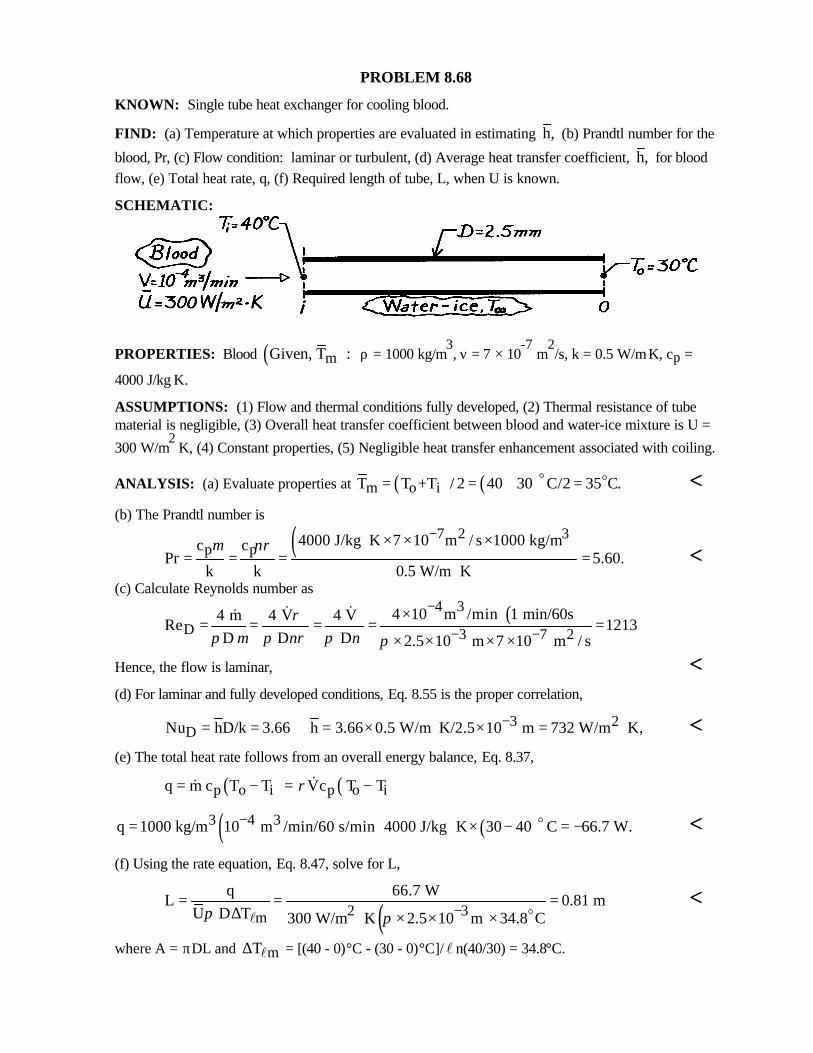
PROBLEM 8.68
KNOWN: Single tube heat exchanger for cooling blood.
FIND: (a) Temperature at which properties are evaluated in estimating h, (b) Prandtl number for the
blood, Pr, (c) Flow condition: laminar or turbulent, (d) Average heat transfer coefficient, h, for bloodflow, (e) Total heat rate, q, (f) Required length of tube, L, when U is known.
SCHEMATIC:
PROPERTIES: Blood ( )mGiven, T : ρ = 1000 kg/m3, ν = 7 × 10
-7 m
2/s, k = 0.5 W/m⋅K, cp =
4000 J/kg⋅K.
ASSUMPTIONS: (1) Flow and thermal conditions fully developed, (2) Thermal resistance of tubematerial is negligible, (3) Overall heat transfer coefficient between blood and water-ice mixture is U =
300 W/m2⋅K, (4) Constant properties, (5) Negligible heat transfer enhancement associated with coiling.
ANALYSIS: (a) Evaluate properties at ( ) ( )m o iT T +T / 2 40 30 C/2 35 C.= = + =o o <(b) The Prandtl number is
( )7 2 3p p
4000 J/kg K 7 10 m / s 1000 kg/mc cPr 5.60.
k k 0.5 W/m K
µ νρ−⋅ × × ×
= = = =⋅
<(c) Calculate Reynolds number as
( )4 3
D 3 7 24 10 m /min 1 min/60s4 m 4 V 4 V
Re 1213D D D 2.5 10 m 7 10 m / s
ρπ µ π νρ π ν π
−
− −×
= = = = =× × × ×
& &&
Hence, the flow is laminar, <(d) For laminar and fully developed conditions, Eq. 8.55 is the proper correlation,
3 2DNu hD/k 3.66 h 3.66 0.5 W/m K/2.5 10 m 732 W/m K,−= = = × ⋅ × = ⋅ <
(e) The total heat rate follows from an overall energy balance, Eq. 8.37,
( ) ( )p o i p o iq m c T T Vc T Tρ= − = −&&
( ) ( )3 4 3q 1000 kg/m 10 m /min/60 s/min 4000 J/kg K 30 40 C 66.7 W.−= ⋅ × − = −o <
(f) Using the rate equation, Eq. 8.47, solve for L,
( )2 3m
q 66.7 WL 0.81 m
U D T 300 W/m K 2.5 10 m 34.8 Cπ π −= = =
∆ ⋅ × × × ol<
where A = πDL and mT∆ l = [(40 - 0)°C - (30 - 0)°C]/l n(40/30) = 34.8°C.
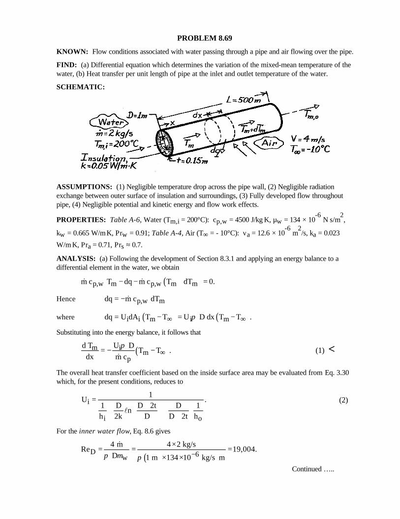
PROBLEM 8.69
KNOWN: Flow conditions associated with water passing through a pipe and air flowing over the pipe.
FIND: (a) Differential equation which determines the variation of the mixed-mean temperature of thewater, (b) Heat transfer per unit length of pipe at the inlet and outlet temperature of the water.
SCHEMATIC:
ASSUMPTIONS: (1) Negligible temperature drop across the pipe wall, (2) Negligible radiationexchange between outer surface of insulation and surroundings, (3) Fully developed flow throughoutpipe, (4) Negligible potential and kinetic energy and flow work effects.
PROPERTIES: Table A-6, Water (Tm,i = 200°C): cp,w = 4500 J/kg⋅K, µw = 134 × 10-6
N⋅s/m2,
kw = 0.665 W/m⋅K, Prw = 0.91; Table A-4, Air (T∞ = - 10°C): νa = 12.6 × 10⁻⁶
m2/s, ka = 0.023
W/m⋅K, Pra = 0.71, Prs ≈ 0.7.
ANALYSIS: (a) Following the development of Section 8.3.1 and applying an energy balance to adifferential element in the water, we obtain
( )p,w m p,w m mm c T dq m c T dT 0.− − + =& &
Hence p,w mdq m c dT= − &
where ( ) ( )i i m i mdq U dA T T U D dx T T .π∞ ∞= − = −
Substituting into the energy balance, it follows that
( )m im
p
d T U DT T .
dx m cπ
∞= − −&
(1) <
The overall heat transfer coefficient based on the inside surface area may be evaluated from Eq. 3.30which, for the present conditions, reduces to
i
i o
1U .
1 D D 2t D 1n
h 2k D D 2t h
=+ + + +
l
(2)
For the inner water flow, Eq. 8.6 gives
( )D 6w
4 m 4 2 kg/sRe 19,004.
D 1 m 134 10 kg/s mπ µ π −×= = =
× × ⋅
&
Continued …..
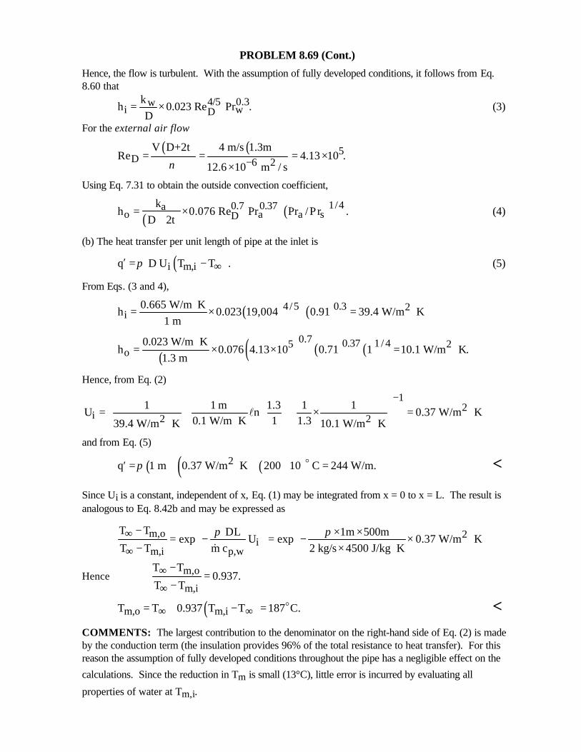
PROBLEM 8.69 (Cont.)
Hence, the flow is turbulent. With the assumption of fully developed conditions, it follows from Eq.8.60 that
4/5 0.3wi wD
kh 0.023 Re Pr .
D= × (3)
For the external air flow
( ) ( ) 5D 6 2
V D+2t 4 m/s 1.3mRe 4.13 10 .
12.6 10 m / sν −= = = ××
Using Eq. 7.31 to obtain the outside convection coefficient,
( ) ( )1/40.7 0.37ao a a sD
kh 0.076 Re Pr Pr /Pr .
D 2t= ×
+(4)
(b) The heat transfer per unit length of pipe at the inlet is
( )i m,iq D U T T .π ∞′ = − (5)
From Eqs. (3 and 4),
( ) ( )4/5 0.3 2i
0.665 W/m Kh 0.023 19,004 0.91 39.4 W/m K
1 m⋅= × = ⋅
( ) ( ) ( ) ( )0.7 0.37 1 / 45 2
o0.023 W/m K
h 0.076 4.13 10 0.71 1 10.1 W/m K.1.3 m
⋅= × × = ⋅
Hence, from Eq. (2)
12
i 2 21 1 m 1.3 1 1
U n 0.37 W/m K0.1 W/m K 1 1.339.4 W/m K 10.1 W/m K
− = + + × = ⋅ ⋅ ⋅ ⋅ l
and from Eq. (5)
( ) ( ) ( )2q 1 m 0.37 W/m K 200 10 C 244 W/m.π′ = ⋅ + =o <
Since Ui is a constant, independent of x, Eq. (1) may be integrated from x = 0 to x = L. The result isanalogous to Eq. 8.42b and may be expressed as
m,o 2i
m,i p,w
T T DL 1m 500mexp U exp 0.37 W/m K
T T m c 2 kg/s 4500 J/kg Kπ π∞
∞
− × ×= − = − × ⋅ − × ⋅ &
Hence m,o
m,i
T T0.937.
T T∞
∞
−=
−
( )m,o m,iT T 0.937 T T 187 C.∞ ∞= + − = o <COMMENTS: The largest contribution to the denominator on the right-hand side of Eq. (2) is madeby the conduction term (the insulation provides 96% of the total resistance to heat transfer). For thisreason the assumption of fully developed conditions throughout the pipe has a negligible effect on the
calculations. Since the reduction in Tm is small (13°C), little error is incurred by evaluating all
properties of water at Tm,i.
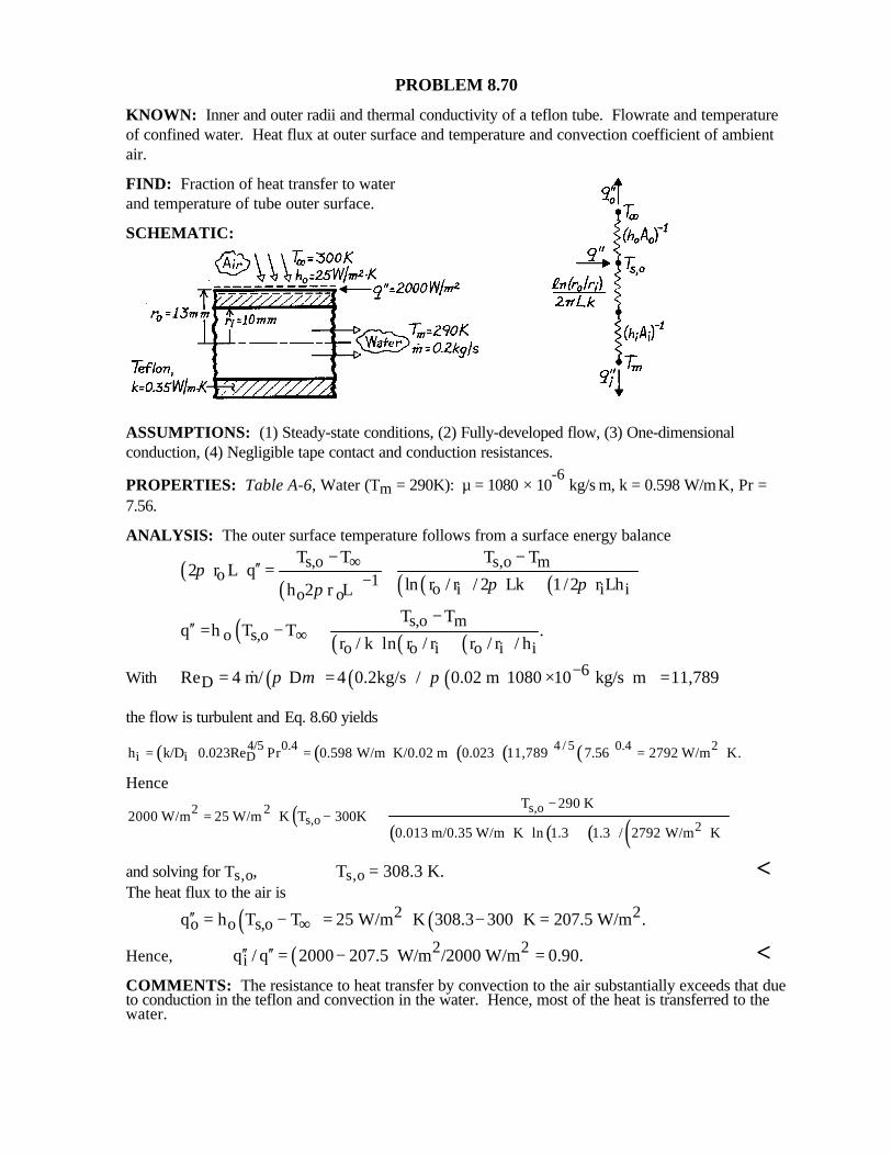
PROBLEM 8.70
KNOWN: Inner and outer radii and thermal conductivity of a teflon tube. Flowrate and temperatureof confined water. Heat flux at outer surface and temperature and convection coefficient of ambientair.
FIND: Fraction of heat transfer to waterand temperature of tube outer surface.
SCHEMATIC:
ASSUMPTIONS: (1) Steady-state conditions, (2) Fully-developed flow, (3) One-dimensionalconduction, (4) Negligible tape contact and conduction resistances.
PROPERTIES: Table A-6, Water (Tm = 290K): µ = 1080 × 10-6
kg/s⋅m, k = 0.598 W/m⋅K, Pr =7.56.
ANALYSIS: The outer surface temperature follows from a surface energy balance
( )( ) ( )( ) ( )
s,o s,o mo 1 o i i io o
T T T T2 r L q
ln r / r / 2 Lk 1/2 r Lhh 2 r Lπ
π ππ
∞−
− −′′ = +
+
( ) ( ) ( ) ( )s,o m
o s,oo o i o i i
T Tq h T T .
r / k ln r / r r / r / h∞−
′′ = − ++
With ( ) ( ) ( ) 6DRe 4 m/ D 4 0.2kg/s / 0.02 m 1080 10 kg/s m 11,789π µ π − = = × ⋅ =
&
the flow is turbulent and Eq. 8.60 yields
( ) ( )( )( ) ( )4 / 5 0.44/5 0.4 2i i Dh k/D 0.023Re Pr 0.598 W/m K/0.02 m 0.023 11,789 7.56 2792 W/m K.= = ⋅ = ⋅
Hence
( )( ) ( ) ( ) ( )
s,o2 2s,o 2
T 290 K2000 W/m 25 W/m K T 300K
0.013 m/0.35 W/m K ln 1.3 1.3 / 2792 W/m K
−= ⋅ − +
⋅ + ⋅
and solving for Ts,o, Ts,o = 308.3 K. <The heat flux to the air is
( ) ( )2 2o o s,oq h T T 25 W/m K 308.3 300 K 207.5 W/m .∞′′ = − = ⋅ − =
Hence, ( ) 2 2iq / q 2000 207.5 W/m /2000 W/m 0.90.′′ ′′ = − = <
COMMENTS: The resistance to heat transfer by convection to the air substantially exceeds that dueto conduction in the teflon and convection in the water. Hence, most of the heat is transferred to thewater.
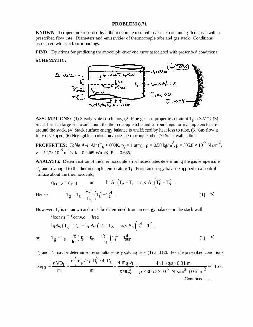
PROBLEM 8.71
KNOWN: Temperature recorded by a thermocouple inserted in a stack containing flue gases with aprescribed flow rate. Diameters and emissivities of thermocouple tube and gas stack. Conditionsassociated with stack surroundings.
FIND: Equations for predicting thermocouple error and error associated with prescribed conditions.
SCHEMATIC:
ASSUMPTIONS: (1) Steady-state conditions, (2) Flue gas has properties of air at Tg ≈ 327°C, (3)Stack forms a large enclosure about the thermocouple tube and surroundings form a large enclosurearound the stack, (4) Stack surface energy balance is unaffected by heat loss to tube, (5) Gas flow isfully developed, (6) Negligible conduction along thermocouple tube, (7) Stack wall is thin.
PROPERTIES: Table A-4, Air (Tg ≈ 600K, pg = 1 atm): ρ = 0.58 kg/m3, µ = 305.8 × 10
-7 N⋅s/m
2,
ν = 52.7× 10⁻⁶
m2/s, k = 0.0469 W/m⋅K, Pr = 0.685.
ANALYSIS: Determination of the thermocouple error necessitates determining the gas temperature
Tg and relating it to the thermocouple temperature Tt. From an energy balance applied to a controlsurface about the thermocouple,
( ) ( )4 4conv rad t t g t t t t sq q or h A T T A T T .ε σ= − = −
Hence ( )4 4tg t t s
tT T T T .
hε σ= + − (1) <
However, Ts is unknown and must be determined from an energy balance on the stack wall.
conv,i conv,o radq q q= +
( ) ( ) ( )4 4i s g s o s s s s s surh A T T h A T T A T Tε σ∞− = − + −
or ( ) ( )4 4o sg s s s sur
i i
hT T T T T T .
h hε σ
∞= + − + − (2) <
Tg and Ts may be determined by simultaneously solving Eqs. (1) and (2). For the prescribed conditions
( )( )
2g s t g tt
Dt 2 2-7 2s
m / D / 4 D 4 m DVD 4 1 kg/s 0.01 mRe 1157.
D 305.8 10 N s/m 0.6 m
ρ ρπρµ µ πµ π
× ×= = = = =× × ⋅
& &
Continued …..
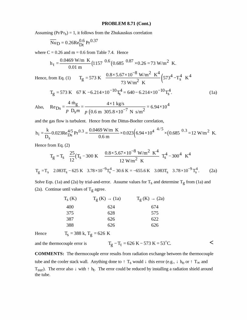
PROBLEM 8.71 (Cont.)
Assuming (Pr/Prs) = 1, it follows from the Zhukauskus correlation
0.6 0.37D DtNu 0.26Re Pr=
where C = 0.26 and m = 0.6 from Table 7.4. Hence
( ) ( )0.6 0.87 2t
0.0469 W/m Kh 1157 0.685 0.26 73 W/m K.
0.01 m⋅= × = ⋅
Hence, from Eq. (1) ( )8 2 44 4 4
g s20.8 5.67 10 W/m K
T 573 K 573 T K73 W/m K
−× × ⋅= + −⋅
10 4 10 4g s sT 573 K 67 K 6.214 10 T 640 6.214 10 T .− −= + − × = − × (1a)
Also,( )
g 4Ds 7 2s
4 m 4 1 kg/sRe 6.94 10
D 0.6 m 305.8 10 N s/mπ µ π −×= = = ×
× ⋅
&
and the gas flow is turbulent. Hence from the Dittus-Boelter correlation,
( ) ( )4 / 5 0.34/5 0.3 4 2
i Dss
k 0.0469 W/m Kh 0.023Re Pr 0.023 6.94 10 0.685 12 W/m K.
D 0.6 m⋅= = × × × = ⋅
Hence from Eq. (2)
( )8 2 4
4 4 4g s s s2
25 0.8 5.67 10 W/m KT T T 300 K T 300 K
12 12 W/m K
−× × ⋅ = + − + − ⋅9 4 9 4
g s s s s sT T 2.083T 625 K 3.78 10 T 30.6 K 655.6 K 3.083T 3.78 10 T .− −= + − + × − = − + + × (2a)
Solve Eqs. (1a) and (2a) by trial-and-error. Assume values for Ts and determine Tg from (1a) and
(2a). Continue until values of Tg agree.
Ts (K) Tg (K) → (1a) Tg (K) → (2a)
400 624 674 375 628 575 387 626 622 388 626 626
Hence s gT 388 k, T 626 K= =
and the thermocouple error is g tT T 626 K 573 K 53 C.− = − = o <COMMENTS: The thermocouple error results from radiation exchange between the thermocouple
tube and the cooler stack wall. Anything done to ↑ Ts would ↓ this error (e.g., ↓ ho or ↑ T∞ and
Tsur). The error also ↓ with ↑ ht. The error could be reduced by installing a radiation shield aroundthe tube.
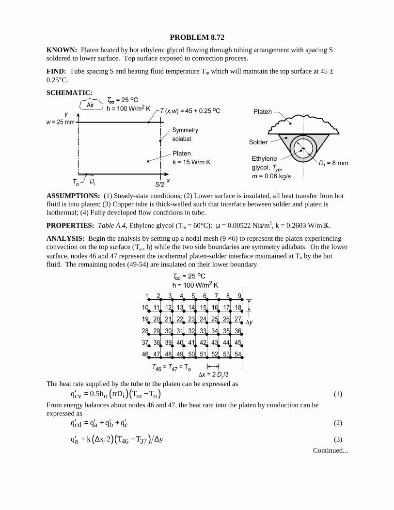
PROBLEM 8.72
KNOWN: Platen heated by hot ethylene glycol flowing through tubing arrangement with spacing Ssoldered to lower surface. Top surface exposed to convection process.
FIND: Tube spacing S and heating fluid temperature Tm which will maintain the top surface at 45 ±0.25°C.
SCHEMATIC:
ASSUMPTIONS: (1) Steady-state conditions; (2) Lower surface is insulated, all heat transfer from hotfluid is into platen; (3) Copper tube is thick-walled such that interface between solder and platen isisothermal; (4) Fully developed flow conditions in tube.
PROPERTIES: Table A.4, Ethylene glycol (Tm = 60°C): µ = 0.00522 N⋅s/m2, k = 0.2603 W/m⋅K.
ANALYSIS: Begin the analysis by setting up a nodal mesh (9 ×6) to represent the platen experiencingconvection on the top surface (T∞ , h) while the two side boundaries are symmetry adiabats. On the lowersurface, nodes 46 and 47 represent the isothermal platen-solder interface maintained at To by the hotfluid. The remaining nodes (49-54) are insulated on their lower boundary.
The heat rate supplied by the tube to the platen can be expressed as
( )( )cv o i m oq 0.5h D T Tπ′ = − (1)
From energy balances about nodes 46 and 47, the heat rate into the platen by conduction can beexpressed as
cd a b cq q q q′ ′ ′ ′= + + (2)
( )( )a 46 37q k x 2 T T y′ = ∆ − ∆ (3)
Continued...
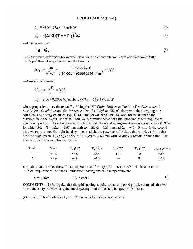
PROBLEM 8.72 (Cont.)
( )( )b 47 38q k x T T y′ = ∆ − ∆ (4)
( )( )c 47 48q k y 2 T T x′ = ∆ − ∆ (5)
and we require that
cd cvq q′ ′= (6)
The convection coefficient for internal flow can be estimated from a correlation assuming fullydeveloped flow. First, characterize the flow with
( )D 2i
4m 4 0.06kg sRe 1829
D 0.008m 0.00522 N s mπ µ π×= = =
⋅
�
and since it is laminar,
o iD
h DNu 3.66
k= =
oh 3.66 0.2603W m K 0.008m 119.1W m K= × ⋅ = ⋅
where properties are evaluated at Tm. Using the IHT Finite-Difference Tool for Two-DimensionalSteady-State Conditions and the Properties Tool for Ethylene Glycol, along with the foregoing rateequations and energy balances, Eqs. (1-6), a model was developed to solve for the temperaturedistribution in the platen. In the solution, we determined what hot fluid temperature was required tomaintain T1 = 45°C. Two trials were run. In the first, the nodal arrangement was as shown above (9 × 6)for which S/2 = (9 - 1)∆x = 42.67 mm with ∆x = 2Di/3 = 5.33 mm and ∆y = w/5 = 5 mm. In the secondtrial, we repositioned the right-hand symmetry adiabat to pass vertically through the nodes 6-51 so thatnow the nodal mesh is (6 × 6) and S/2 = (6 - 1)∆x = 26.65 mm with ∆x and ∆y remaining the same. Theresults of the trials are tabulated below.
Trial Mesh T1 (°C) T6 (°C) T9 (°C) Tm (°C) cvq′ (W/m)
1 9 × 6 45.0 43.5 43.0 105 80.52 6 × 6 45.0 44.5 --- 85 52.6
From the trial 2 results, the surface temperature uniformity is (T1 - T6) = 0.5°C which satisfies the±0.25°C requirement. So that suitable tube spacing and fluid temperature are
S = 53 mm Tm = 85°C <COMMENTS: (1) Recognize that the grid spacing is quite coarse and good practice demands that werepeat the analysis decreasing the nodal spacing until no further changes are seen in Tm.
(2) In the first trial, note that Tm = 105°C which of course, is not possible.
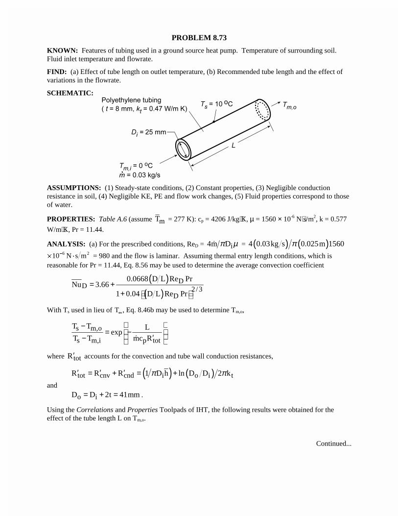
PROBLEM 8.73
KNOWN: Features of tubing used in a ground source heat pump. Temperature of surrounding soil.Fluid inlet temperature and flowrate.
FIND: (a) Effect of tube length on outlet temperature, (b) Recommended tube length and the effect ofvariations in the flowrate.
SCHEMATIC:
ASSUMPTIONS: (1) Steady-state conditions, (2) Constant properties, (3) Negligible conductionresistance in soil, (4) Negligible KE, PE and flow work changes, (5) Fluid properties correspond to thoseof water.
PROPERTIES: Table A.6 (assume mT = 277 K): cp = 4206 J/kg⋅K, µ = 1560 × 10-6 N⋅s/m2, k = 0.577
W/m⋅K, Pr = 11.44.
ANALYSIS: (a) For the prescribed conditions, ReD = i4m Dπ µ� = ( ) ( )4 0.03kg s 0.025m 1560π� ¹
�10 6 2N s m = 980 and the flow is laminar. Assuming thermal entry length conditions, which isreasonable for Pr = 11.44, Eq. 8.56 may be used to determine the average convection coefficient
( )( )
DD 2/3
D
0.0668 D L Re PrNu 3.66
1 0.04 D L Re Pr= +
+
With Ts used in lieu of T�
, Eq. 8.46b may be used to determine Tm,o,
s m,o
s m,i p tot
T T Lexp
T T mc R
−= − ′− �
where totR′ accounts for the convection and tube wall conduction resistances,
( ) ( )tot cnv cnd i o i tR R R 1 D h ln D D 2 kπ π′ ′ ′= + = +and
o iD D 2t 41mm= + = .
Using the Correlations and Properties Toolpads of IHT, the following results were obtained for theeffect of the tube length L on Tm,o.
Continued...
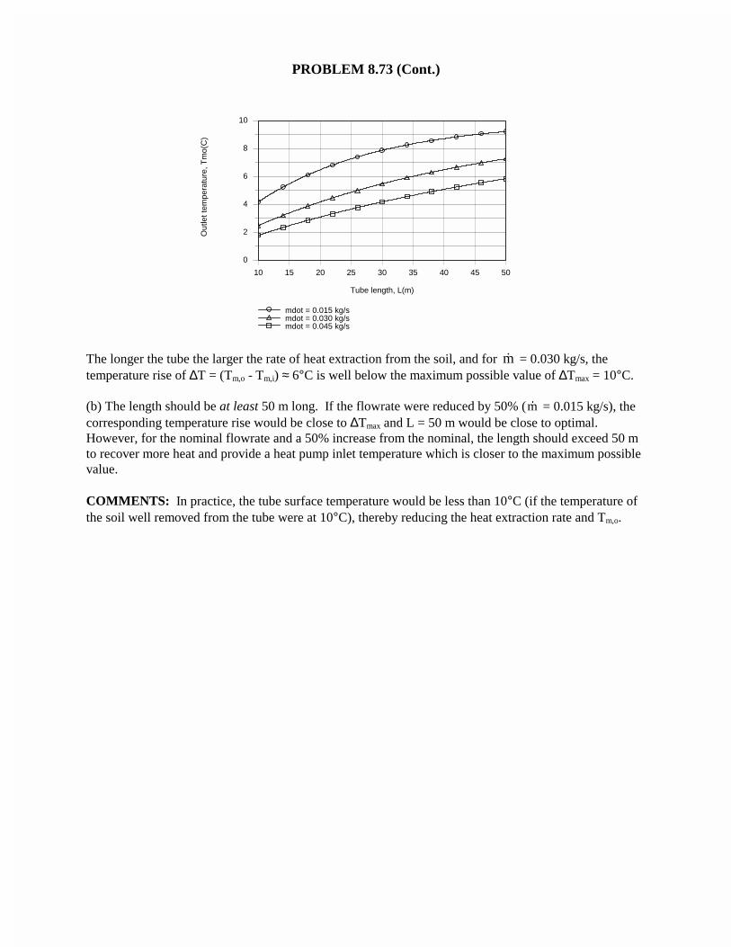
PROBLEM 8.73 (Cont.)
10 15 20 25 30 35 40 45 50
Tube length, L(m)
0
2
4
6
8
10
Out
let t
empe
ratu
re, T
mo(
C)
mdot = 0.015 kg/smdot = 0.030 kg/smdot = 0.045 kg/s
The longer the tube the larger the rate of heat extraction from the soil, and for m� = 0.030 kg/s, thetemperature rise of ∆T = (Tm,o - Tm,i) ≈ 6°C is well below the maximum possible value of ∆Tmax = 10°C.
(b) The length should be at least 50 m long. If the flowrate were reduced by 50% ( �m = 0.015 kg/s), thecorresponding temperature rise would be close to ∆Tmax and L = 50 m would be close to optimal.However, for the nominal flowrate and a 50% increase from the nominal, the length should exceed 50 mto recover more heat and provide a heat pump inlet temperature which is closer to the maximum possiblevalue.
COMMENTS: In practice, the tube surface temperature would be less than 10°C (if the temperature ofthe soil well removed from the tube were at 10°C), thereby reducing the heat extraction rate and Tm,o.
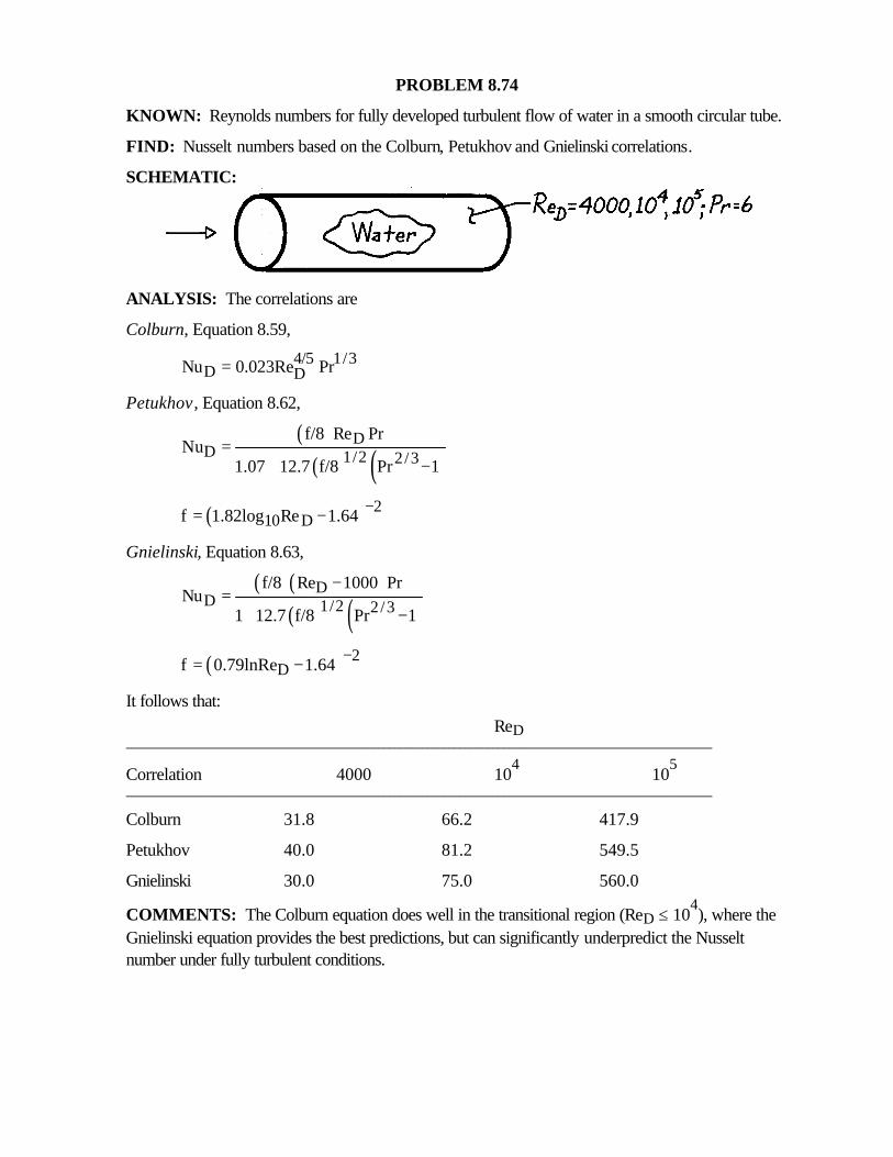
PROBLEM 8.74
KNOWN: Reynolds numbers for fully developed turbulent flow of water in a smooth circular tube.
FIND: Nusselt numbers based on the Colburn, Petukhov and Gnielinski correlations.
SCHEMATIC:
ANALYSIS: The correlations are
Colburn, Equation 8.59,
4/5 1/3D DNu 0.023Re Pr=
Petukhov, Equation 8.62,
( )( ) ( )
DD 1/2 2/3
f/8 Re PrNu
1.07 12.7 f/8 Pr 1=
+ −
( ) 210 Df 1.82log Re 1.64 −= −
Gnielinski, Equation 8.63,
( ) ( )( ) ( )
DD 1/2 2/3
f/8 Re 1000 PrNu
1 12.7 f/8 Pr 1
−=
+ −
( ) 2Df 0.79lnRe 1.64 −= −
It follows that:ReD
___________________________________________________________________________________________________________
Correlation 4000 104
105
___________________________________________________________________________________________________________
Colburn 31.8 66.2 417.9
Petukhov 40.0 81.2 549.5
Gnielinski 30.0 75.0 560.0
COMMENTS: The Colburn equation does well in the transitional region (ReD ≤ 104), where the
Gnielinski equation provides the best predictions, but can significantly underpredict the Nusseltnumber under fully turbulent conditions.
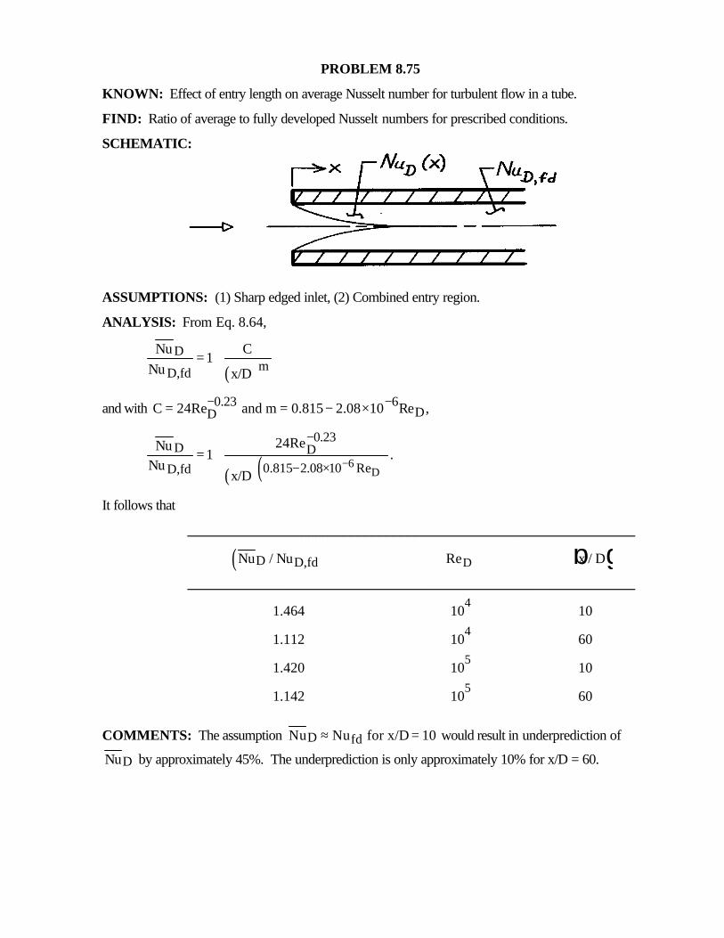
PROBLEM 8.75
KNOWN: Effect of entry length on average Nusselt number for turbulent flow in a tube.
FIND: Ratio of average to fully developed Nusselt numbers for prescribed conditions.
SCHEMATIC:
ASSUMPTIONS: (1) Sharp edged inlet, (2) Combined entry region.
ANALYSIS: From Eq. 8.64,
( )D
mD,fd
Nu C1
Nu x/D= +
and with 0.23 6DDC 24Re and m 0.815 2.08 10 Re ,− −= = − ×
( )( )6D
0.23D D
0.815 2.08 10 ReD,fd
24ReNu1 .
Nux/D
−
−
− ×= +
It follows that
_______________________________________________________________
( )D D,fdNu / Nu ReD x / Db g_______________________________________________________________
1.464 104
10
1.112 104
60
1.420 105
10
1.142 105
60
COMMENTS: The assumption D fdNu Nu for x/D 10≈ = would result in underprediction of
DNu by approximately 45%. The underprediction is only approximately 10% for x/D = 60.
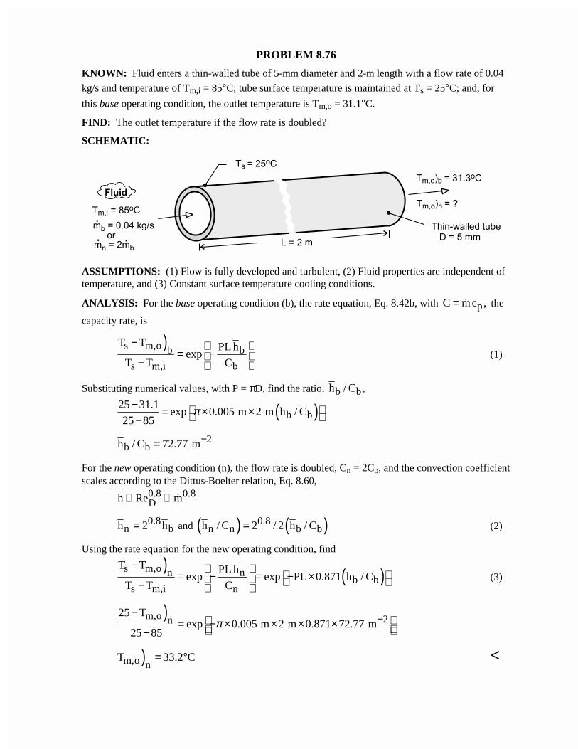
PROBLEM 8.76
KNOWN: Fluid enters a thin-walled tube of 5-mm diameter and 2-m length with a flow rate of 0.04
kg/s and temperature of Tm,i = 85°C; tube surface temperature is maintained at Ts = 25°C; and, for
this base operating condition, the outlet temperature is Tm,o = 31.1°C.
FIND: The outlet temperature if the flow rate is doubled?
SCHEMATIC:
ASSUMPTIONS: (1) Flow is fully developed and turbulent, (2) Fluid properties are independent oftemperature, and (3) Constant surface temperature cooling conditions.
ANALYSIS: For the base operating condition (b), the rate equation, Eq. 8.42b, with pC mc ,= � the
capacity rate, is
)s m,o b b
s m,i b
T T PL hexp
T T C
− = − −
(1)
Substituting numerical values, with P = πD, find the ratio, b bh / C ,
( )b b25 31.1
exp 0.005 m 2 m h / C25 85
π− = × × −2
b bh / C 72.77 m−=
For the new operating condition (n), the flow rate is doubled, Cn = 2Cb, and the convection coefficientscales according to the Dittus-Boelter relation, Eq. 8.60,
0.8 0.8Dh Re m�� �
0.8n bh 2 h= and ( ) ( )0.8
n n b bh / C 2 / 2 h / C= (2)
Using the rate equation for the new operating condition, find
) ( )s m,o nnb b
s m,i n
T T PL hexp exp PL 0.871 h / C
T T C
− = − = − × − (3)
)m,o 2n25 T
exp 0.005 m 2 m 0.871 72.77 m25 85
π −− = − × × × × −
)m,o nT 33.2 C= ° <
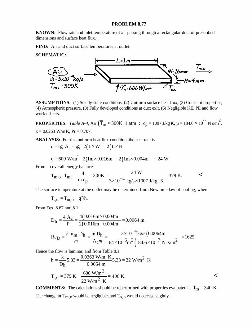
PROBLEM 8.77
KNOWN: Flow rate and inlet temperature of air passing through a rectangular duct of prescribeddimensions and surface heat flux.
FIND: Air and duct surface temperatures at outlet.
SCHEMATIC:
ASSUMPTIONS: (1) Steady-state conditions, (2) Uniform surface heat flux, (3) Constant properties,(4) Atmospheric pressure, (3) Fully developed conditions at duct exit, (6) Negligible KE, PE and flowwork effects.
PROPERTIES: Table A-4, Air ( )mT 300K, 1 atm :≈ cp = 1007 J/kg⋅K, µ = 184.6 × 10⁻⁷
N⋅s/m2,
k = 0.0263 W/m⋅K, Pr = 0.707.
ANALYSIS: For this uniform heat flux condition, the heat rate is
( ) ( )s s sq q A q 2 L W 2 L H′′ ′′ = = × + ×
( ) ( )2q 600 W/m 2 1m 0.016m 2 1m 0.004m 24 W. = × + × = From an overall energy balance
m,o m,i 4p
q 24 WT =T 300K 379 K.
m c 3 10 kg/s 1007 J/kg K−+ = + =
× × ⋅&<
The surface temperature at the outlet may be determined from Newton’s law of cooling, where
s,o m,oT T q /h.′′= +
From Eqs. 8.67 and 8.1
( )( )
ch
4 0.016m 0.004m4 AD 0.0064 m
P 2 0.016m 0.004m
×= = =
+
( )( )4
m h hD 6 2 7 2c
3 10 kg/s 0.0064m u D m DRe 1625.
A 64 10 m 184.6 10 N s/m
ρµ µ
−
− −×
= = = =× × ⋅
&
Hence the flow is laminar, and from Table 8.12
h
k 0.0263 W/m Kh 5.33 5.33 22 W/m K
D 0.0064 m⋅= = = ⋅
2s,o 2
600 W/mT 379 K 406 K.
22 W/m K= + =
⋅<
COMMENTS: The calculations should be reperformed with properties evaluated at T K.m = 340
The change in Tm,o would be negligible, and Ts,o would decrease slightly.
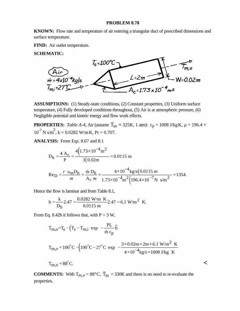
PROBLEM 8.78
KNOWN: Flow rate and temperature of air entering a triangular duct of prescribed dimensions andsurface temperature.
FIND: Air outlet temperature.
SCHEMATIC:
ASSUMPTIONS: (1) Steady-state conditions, (2) Constant properties, (3) Uniform surfacetemperature, (4) Fully developed conditions throughout, (5) Air is at atmospheric pressure, (6)Negligible potential and kinetic energy and flow work effects.
PROPERTIES: Table A-4, Air (assume mT ≈ 325K, 1 atm): cp = 1008 J/kg⋅K, µ = 196.4 ×
10-7 N⋅s/m2, k = 0.0282 W/m⋅K, Pr = 0.707.
ANALYSIS: From Eqs. 8.67 and 8.1
( )( )
4 2c
h4 1.73 10 m4 A
D 0.0115 mP 3 0.02m
−×= = =
( )( )
4m h h
D 4 2 7 2c
4 10 kg/s 0.0115 m u D m DRe 1354.
A 1.73 10 m 196.4 10 N s/m
ρµ µ
−
− −×
= = = =× × ⋅
&
Hence the flow is laminar and from Table 8.1,
2
h
k 0.0282 W/m Kh 2.47 2.47 6.1 W/m K.
D 0.0115 m⋅= = = ⋅
From Eq. 8.42b it follows that, with P = 3 W,
( )m,o s s m,ip
PLT =T T T exp h
m c
− − − &
( )2
m,o 43 0.02m 2m 6.1 W/m K
T 100 C 100 C 27 C exp4 10 kg/s 1008 J/kg K−
× × × ⋅ = − − − × × ⋅
o o o
m,oT 88 C.= o <
COMMENTS: With Tm,o = 88°C, mT = 330K and there is no need to re-evaluate theproperties.
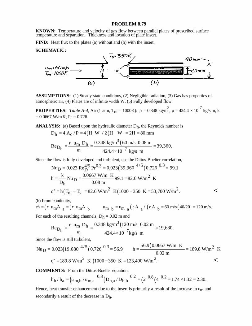
PROBLEM 8.79KNOWN: Temperature and velocity of gas flow between parallel plates of prescribed surfacetemperature and separation. Thickness and location of plate insert.
FIND: Heat flux to the plates (a) without and (b) with the insert.
SCHEMATIC:
ASSUMPTIONS: (1) Steady-state conditions, (2) Negligible radiation, (3) Gas has properties ofatmospheric air, (4) Plates are of infinite width W, (5) Fully developed flow.
PROPERTIES: Table A-4, Air (1 atm, Tm = 1000K): ρ = 0.348 kg/m3, µ = 424.4 × 10
-7 kg/s⋅m, k
= 0.0667 W/m⋅K, Pr = 0.726.
ANALYSIS: (a) Based upon the hydraulic diameter Dh, the Reynolds number is
( ) ( )h cD 4 A / P 4 H W / 2 H W 2H 80 mm= = ⋅ + = =
( )h
3m h
D 70.348 kg/m 60 m/s 0.08 m u D
Re 39,360.424.4 10 kg/s m
ρµ −
= = =× ⋅
Since the flow is fully developed and turbulent, use the Dittus-Boelter correlation,
( ) ( )4/5 0.34/5 0.3D DNu 0.023 Re Pr 0.023 39,360 0.726 99.1= = =
2D
h
k 0.0667 W/m Kh Nu 99.1 82.6 W/m K
D 0.08 m⋅= = = ⋅
( ) ( )2 2m sq h T T 82.6 W/m K 1000 350 K 53,700 W/m .′′ = − = ⋅ − = <
(b) From continuity,( ) ( ) ) ) ( ) ( ) ( )m m m ma b b a a bm u A u A u u A / A 60 m/s 40/20 120 m/s.ρ ρ ρ ρ= = = = =&
For each of the resulting channels, Dh = 0.02 m and
( )h
3m h
D 70.348 kg/m 120 m/s 0.02 m u D
Re 19,680.424.4 10 kg/s m
ρµ −
= = =× ⋅
Since the flow is still turbulent,
( ) ( ) ( )4/5 0.3 2D
56.9 0.0667 W/m KNu 0.023 19,680 0.726 56.9 h 189.8 W/m K
0.02 m
⋅= = = = ⋅
( )2 2q 189.8 W/m K 1000 350 K 123,400 W/m .′′ = ⋅ − = <COMMENTS: From the Dittus-Boelter equation,
( ) ( ) ( ) ( )0.8 0.2 0.8 0.2b a m,b m,a h,a h,bh / h u / u D / D 2 4 1.74 1.32 2.30.= = = × =
Hence, heat transfer enhancement due to the insert is primarily a result of the increase in um and
secondarily a result of the decrease in Dh.
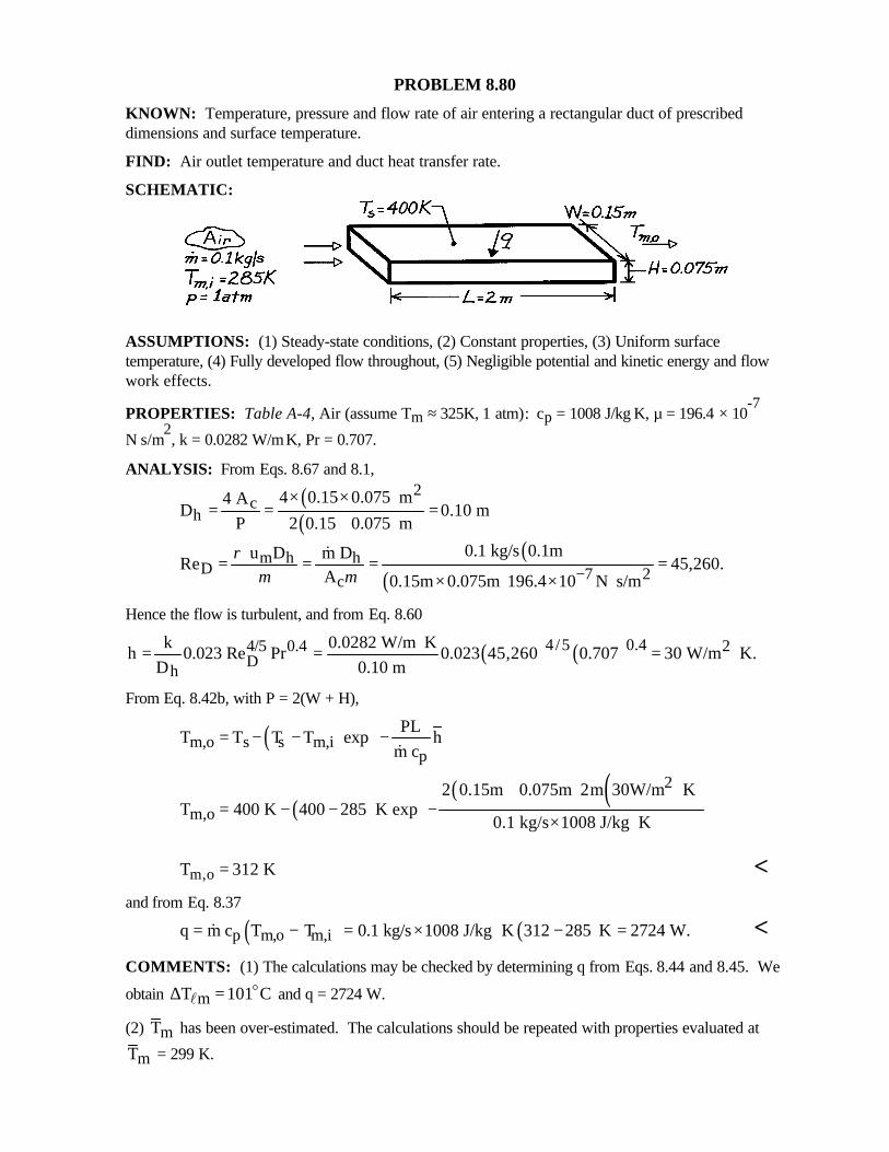
PROBLEM 8.80
KNOWN: Temperature, pressure and flow rate of air entering a rectangular duct of prescribeddimensions and surface temperature.
FIND: Air outlet temperature and duct heat transfer rate.
SCHEMATIC:
ASSUMPTIONS: (1) Steady-state conditions, (2) Constant properties, (3) Uniform surfacetemperature, (4) Fully developed flow throughout, (5) Negligible potential and kinetic energy and flowwork effects.
PROPERTIES: Table A-4, Air (assume Tm ≈ 325K, 1 atm): cp = 1008 J/kg⋅K, µ = 196.4 × 10⁻⁷
N⋅s/m2, k = 0.0282 W/m⋅K, Pr = 0.707.
ANALYSIS: From Eqs. 8.67 and 8.1,
( )( )
2c
h4 0.15 0.075 m4 A
D 0.10 mP 2 0.15 0.075 m
× ×= = =
+
( )( )
m h hD 7 2c
0.1 kg/s 0.1m u D m DRe 45,260.
A 0.15m 0.075m 196.4 10 N s/m
ρµ µ −= = = =
× × ⋅
&
Hence the flow is turbulent, and from Eq. 8.60
( ) ( )4/5 0.44/5 0.4 2D
h
k 0.0282 W/m Kh 0.023 Re Pr 0.023 45,260 0.707 30 W/m K.
D 0.10 m⋅= = = ⋅
From Eq. 8.42b, with P = 2(W + H),
( )m,o s s m,ip
PLT T T T exp h
m c
= − − − &
( )( ) ( )2
m,o2 0.15m 0.075m 2m 30W/m K
T 400 K 400 285 K exp0.1 kg/s 1008 J/kg K
+ ⋅ = − − − × ⋅
m,oT 312 K= <and from Eq. 8.37
( ) ( )p m,o m,iq m c T T 0.1 kg/s 1008 J/kg K 312 285 K 2724 W.= − = × ⋅ − =& <COMMENTS: (1) The calculations may be checked by determining q from Eqs. 8.44 and 8.45. We
obtain mT 101 C∆ = ol and q = 2724 W.
(2) mT has been over-estimated. The calculations should be repeated with properties evaluated at
mT = 299 K.
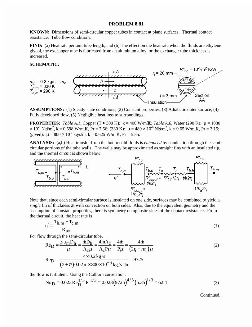
PROBLEM 8.81
KNOWN: Dimensions of semi-circular copper tubes in contact at plane surfaces. Thermal contactresistance. Tube flow conditions.
FIND: (a) Heat rate per unit tube length, and (b) The effect on the heat rate when the fluids are ethyleneglycol, the exchanger tube is fabricated from an aluminum alloy, or the exchanger tube thickness isincreased.
SCHEMATIC:
ASSUMPTIONS: (1) Steady-state conditions, (2) Constant properties, (3) Adiabatic outer surface, (4)Fully developed flow, (5) Negligible heat loss to surroundings.
PROPERTIES: Table A.1, Copper (T ≈ 300 K): k = 400 W/m⋅K; Table A.6, Water (290 K): µ = 1080× 10-6 N⋅s/m2, k = 0.598 W/m⋅K, Pr = 7.56; (330 K): µ = 489 × 10-6 N⋅s/m2, k = 0.65 W/m⋅K, Pr = 3.15;(given): µ = 800 × 10-6 kg/s⋅m, k = 0.625 W/m⋅K, Pr = 5.35.
ANALYSIS: (a,b) Heat transfer from the hot to cold fluids is enhanced by conduction through the semi-circular portions of the tube walls. The walls may be approximated as straight fins with an insulated tip,and the thermal circuit is shown below.
Note that, since each semi-circular surface is insulated on one side, surfaces may be combined to yield asingle fin of thickness 2t with convection on both sides. Also, due to the equivalent geometry and theassumption of constant properties, there is symmetry on opposite sides of the contact resistance. Fromthe thermal circuit, the heat rate is
h,m c,m
tot
T Tq
R
−′ =
′(1)
For flow through the semi-circular tube,
( )cm h h
Dc c i i
4mAu D mD 4m 4mRe
A A P P 2r r
ρµ µ µ µ π µ
= = = = =+
�� � �(2)
( )D 64 0.2kg s
Re 97252 0.02 m 800 10 kg s mπ −
×= =+ × × ⋅
the flow is turbulent. Using the Colburn correlation,
( ) ( )4 /5 1/34 /5 1/ 3D DNu 0.023Re Pr 0.023 9725 5.35 62.4= = = (3)
Continued...
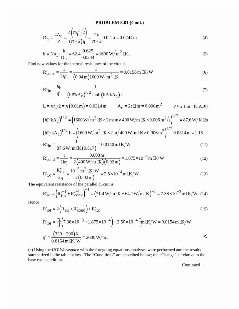
PROBLEM 8.81 (Cont.)
( )( )
2ic
hi
4 r 24A 2D 0.02m 0.0244 m
P 2 r 2
π ππ π
= = = =+ +
(4)
2D
h
k 0.625h Nu 62.4 1600 W m K
D 0.0244= = = ⋅ . (5)
Find now values for the thermal resistance of the circuit.
( )conv 2i
1 1R 0.0156m K W
2r h 0.04m 1600 W m K′ = = = ⋅
⋅(6)
( ) ( )b
fin 1/ 2f c c
1R
q hP kA tanh hP kA L
θ′ = =′ ′ ′
(7)
( )iL r 2 0.01m 0.0314 mπ π= = = 2cA 2t 1m 0.006m= ⋅ = P ≈ 2.1 m (8,9,10)
( ) ( )1/ 21/ 2 2 2chP kA 1600 W m K 2m m 400 W m K 0.006m s 87.6 W K m′ ′ = ⋅ × × ⋅ × = ⋅
( ) ( )1/ 21/ 2 2 2chP kA L 1600 W m K 2 m 400 W m K 0.006 m 0.0314m 1.15= ⋅ × ⋅ × =
( )fin1
R 0.0140m K W87.6 W m K 0.817
′ = = ⋅⋅
(11)
( )( )4
condi
t 0.003mR 1.875 10 m K W
2kr 2 400 W m K 0.02 m−′ = = = × ⋅
⋅(12)
( )5 2
t,c 4t,c
i
R 10 m K WR 2.5 10 m K W
2r 2 0.02m
−−′′ ⋅′ = = = × ⋅ (13)
The equivalent resistance of the parallel circuit is
( ) ( )1 11 1 3
eq convfinR R R 71.4 W m K 64.1W m K 7.38 10 m K W− −− − −′ ′ ′= + = ⋅ + ⋅ = × ⋅ (14)
Hence
( )tot eq cond t,cR 2 R R R′ ′ ′ ′= + + (15)
( )3 4 4totR 2 7.38 10 1.875 10 2.50 10 m K W 0.0154m K W− − − ′ = × + × + × ⋅ = ⋅
( )330 290 Kq 2600 W m
0.0154 m K W
−′ = =
⋅. <
(c) Using the IHT Workspace with the foregoing equations, analyses were performed and the resultssummarized in the table below. The “Conditions” are described below; the “Change” is relative to thebase case condition.
Continued …..
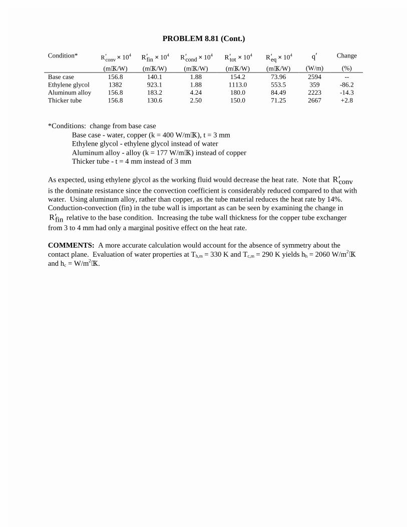
PROBLEM 8.81 (Cont.)
Condition*convR ′ × 104
finR ′ × 104condR ′ × 104
totR ′ × 104eqR ′ × 104 q′ Change
(m⋅K/W) (m⋅K/W) (m⋅K/W) (m⋅K/W) (m⋅K/W) (W/m) (%)Base case 156.8 140.1 1.88 154.2 73.96 2594 --Ethylene glycol 1382 923.1 1.88 1113.0 553.5 359 -86.2Aluminum alloy 156.8 183.2 4.24 180.0 84.49 2223 -14.3Thicker tube 156.8 130.6 2.50 150.0 71.25 2667 +2.8
*Conditions: change from base caseBase case - water, copper (k = 400 W/m⋅K), t = 3 mmEthylene glycol - ethylene glycol instead of waterAluminum alloy - alloy (k = 177 W/m⋅K) instead of copperThicker tube - t = 4 mm instead of 3 mm
As expected, using ethylene glycol as the working fluid would decrease the heat rate. Note that convR′is the dominate resistance since the convection coefficient is considerably reduced compared to that withwater. Using aluminum alloy, rather than copper, as the tube material reduces the heat rate by 14%.Conduction-convection (fin) in the tube wall is important as can be seen by examining the change in
finR′ relative to the base condition. Increasing the tube wall thickness for the copper tube exchangerfrom 3 to 4 mm had only a marginal positive effect on the heat rate.
COMMENTS: A more accurate calculation would account for the absence of symmetry about thecontact plane. Evaluation of water properties at Th,m = 330 K and Tc,m = 290 K yields hh = 2060 W/m2⋅Kand hc = W/m2⋅K.
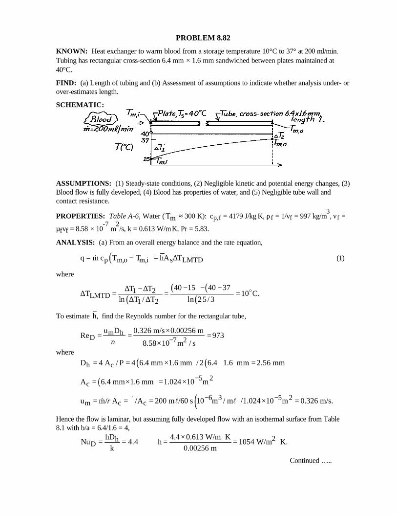
PROBLEM 8.82
KNOWN: Heat exchanger to warm blood from a storage temperature 10°C to 37° at 200 ml/min.Tubing has rectangular cross-section 6.4 mm × 1.6 mm sandwiched between plates maintained at40°C.
FIND: (a) Length of tubing and (b) Assessment of assumptions to indicate whether analysis under- orover-estimates length.
SCHEMATIC:
ASSUMPTIONS: (1) Steady-state conditions, (2) Negligible kinetic and potential energy changes, (3)Blood flow is fully developed, (4) Blood has properties of water, and (5) Negligible tube wall andcontact resistance.
PROPERTIES: Table A-6, Water ( mT ≈ 300 K): cp,f = 4179 J/kg⋅K, ρf = 1/vf = 997 kg/m3, νf =
µfvf = 8.58 × 10⁻⁷
m2/s, k = 0.613 W/m⋅K, Pr = 5.83.
ANALYSIS: (a) From an overall energy balance and the rate equation,
( )p m,o m,i s LMTDq m c T T hA T= − = ∆& (1)
where
( )( ) ( )
( )1 2
LMTD1 2
40 15 40 37T TT 10 C.
ln T / T ln 25 /3
− − −∆ − ∆∆ = = =∆ ∆
o
To estimate h, find the Reynolds number for the rectangular tube,
m hD 7 2
u D 0.326 m/s 0.00256 mRe 973
8.58 10 m / sν −×= = =
×where
( ) ( )h cD 4 A / P 4 6.4 mm 1.6 mm / 2 6.4 1.6 mm 2.56 mm= = × + =
( ) 5 2cA 6.4 mm 1.6 mm 1.024 10 m−= × = ×
( )6 3 5 2m c cu m/ A /A 200 m /60 s 10 m / m /1.024 10 m 0.326 m/s.ρ − −= = ∀ = × =&& l l
Hence the flow is laminar, but assuming fully developed flow with an isothermal surface from Table8.1 with b/a = 6.4/1.6 = 4,
2hD
hD 4.4 0.613 W/m KNu 4.4 h 1054 W/m K.
k 0.00256 m× ⋅= = = = ⋅
Continued …..
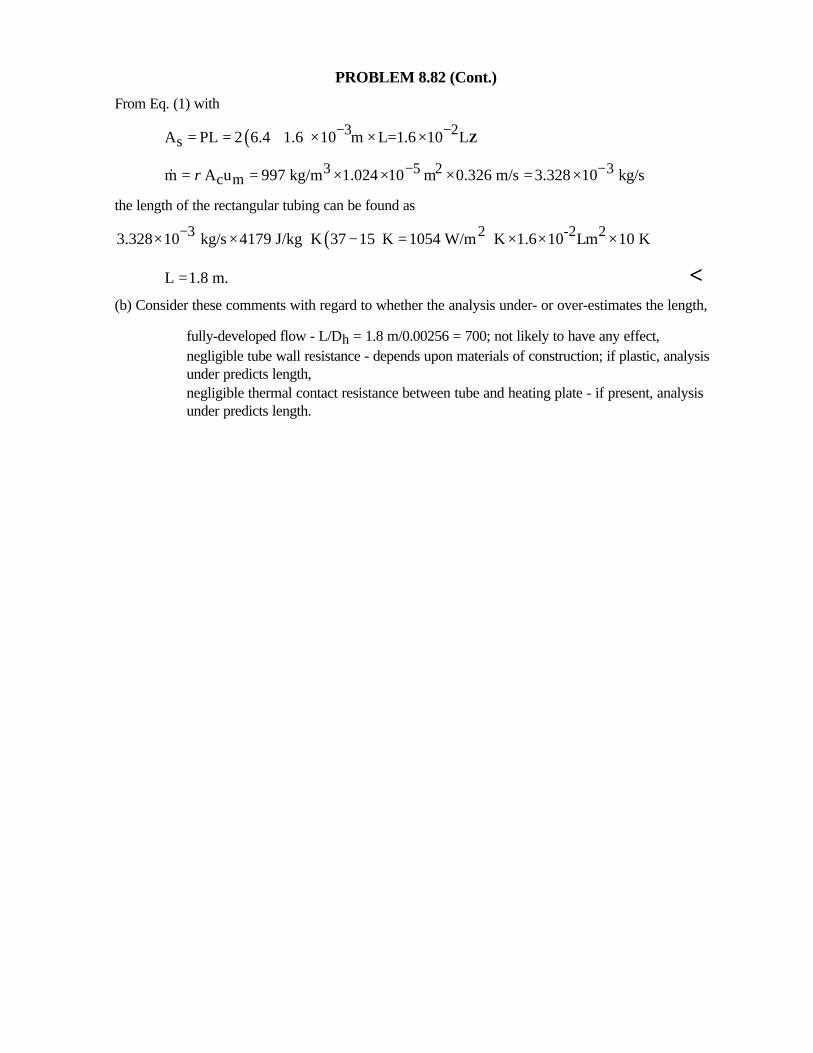
PROBLEM 8.82 (Cont.)
From Eq. (1) with
( ) 3 2sA PL 2 6.4 1.6 10 m L=1.6 10 L− −= = + × × × Z
3 5 2 3c mm A u 997 kg/m 1.024 10 m 0.326 m/s 3.328 10 kg/sρ − −= = × × × = ×&
the length of the rectangular tubing can be found as
( )3 2 -2 23.328 10 kg/s 4179 J/kg K 37 15 K 1054 W/m K 1.6 10 Lm 10 K−× × ⋅ − = ⋅ × × ×
L 1.8 m.= <(b) Consider these comments with regard to whether the analysis under- or over-estimates the length,
⇒ fully-developed flow - L/Dh = 1.8 m/0.00256 = 700; not likely to have any effect,⇒ negligible tube wall resistance - depends upon materials of construction; if plastic, analysis
under predicts length,⇒ negligible thermal contact resistance between tube and heating plate - if present, analysis
under predicts length.
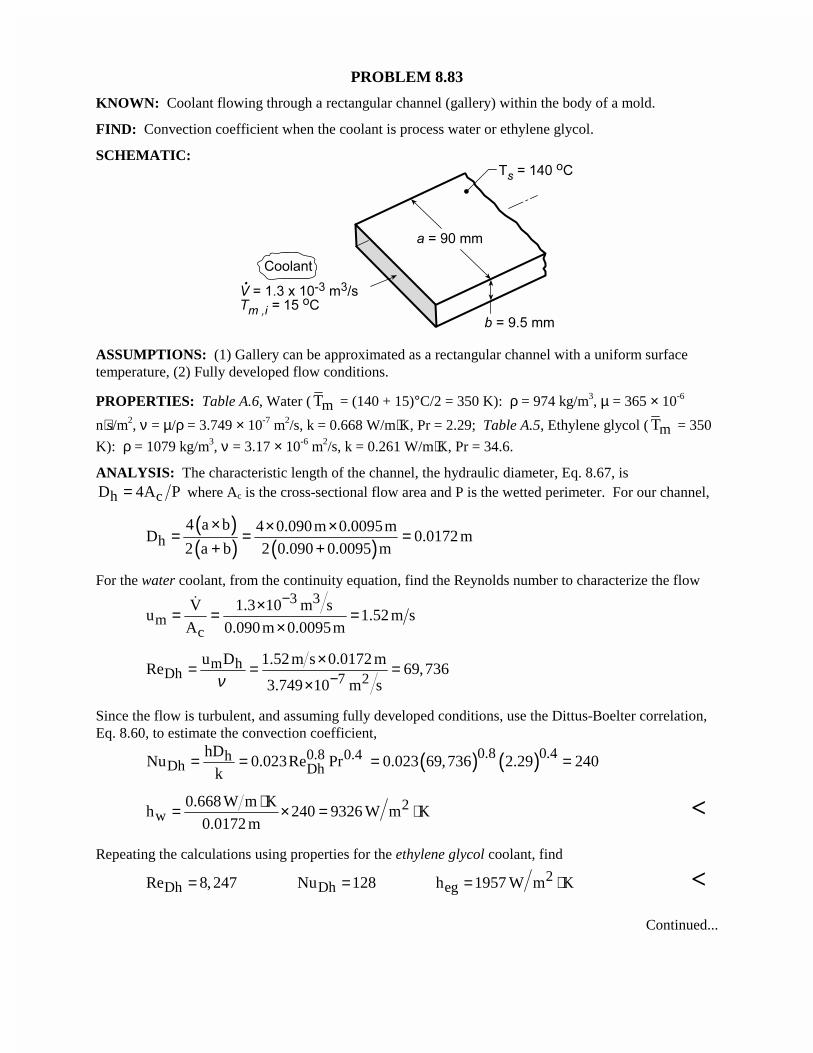
PROBLEM 8.83
KNOWN: Coolant flowing through a rectangular channel (gallery) within the body of a mold.
FIND: Convection coefficient when the coolant is process water or ethylene glycol.
SCHEMATIC:
ASSUMPTIONS: (1) Gallery can be approximated as a rectangular channel with a uniform surfacetemperature, (2) Fully developed flow conditions.
PROPERTIES: Table A.6, Water ( mT = (140 + 15)°C/2 = 350 K): ρ = 974 kg/m3, µ = 365 × 10-6
n⋅s/m2, ν = µ/ρ = 3.749 × 10⁻⁷ m2/s, k = 0.668 W/m⋅K, Pr = 2.29; Table A.5, Ethylene glycol ( mT = 350
K): ρ = 1079 kg/m3, ν = 3.17 × 10⁻⁶ m2/s, k = 0.261 W/m⋅K, Pr = 34.6.
ANALYSIS: The characteristic length of the channel, the hydraulic diameter, Eq. 8.67, is
h cD 4A P= where Ac is the cross-sectional flow area and P is the wetted perimeter. For our channel,
( )( ) ( )h
4 a b 4 0.090m 0.0095mD 0.0172 m
2 a b 2 0.090 0.0095 m
× × ×= = =+ +
For the water coolant, from the continuity equation, find the Reynolds number to characterize the flow3 3
mc
V 1.3 10 m su 1.52 m s
A 0.090m 0.0095m
−×= = =×
�
m hDh 7 2
u D 1.52m s 0.0172 mRe 69,736
3.749 10 m sν −×= = =
×
Since the flow is turbulent, and assuming fully developed conditions, use the Dittus-Boelter correlation,Eq. 8.60, to estimate the convection coefficient,
0.8 0.4hDh Dh
hDNu 0.023Re Pr
k= = ( ) ( )0.8 0.40.023 69,736 2.29 240= =
2w
0.668 W m Kh 240 9326 W m K
0.0172 m⋅= × = ⋅ <
Repeating the calculations using properties for the ethylene glycol coolant, find
DhRe 8, 247= DhNu 128= 2egh 1957 W m K= ⋅ <
Continued...

PROBLEM 8.83 (Cont.)
COMMENTS: (1) The convection coefficient for the water coolant is more than 4 times greater thanthat with the ethylene glycol coolant. The corrosion protection afforded by the latter coolant greatlycompromises the thermal performance of the gallery. In such situations, it is useful to explore acompromise between corrosion protection and thermal performance by using an aqueous solution ofethylene glycol (50%-50%, for example).
(2) Recognize that for the ethylene glycol coolant calculation the Reynolds number is slightly below thelower limit of applicability of the Dittus-Boelter correlation.
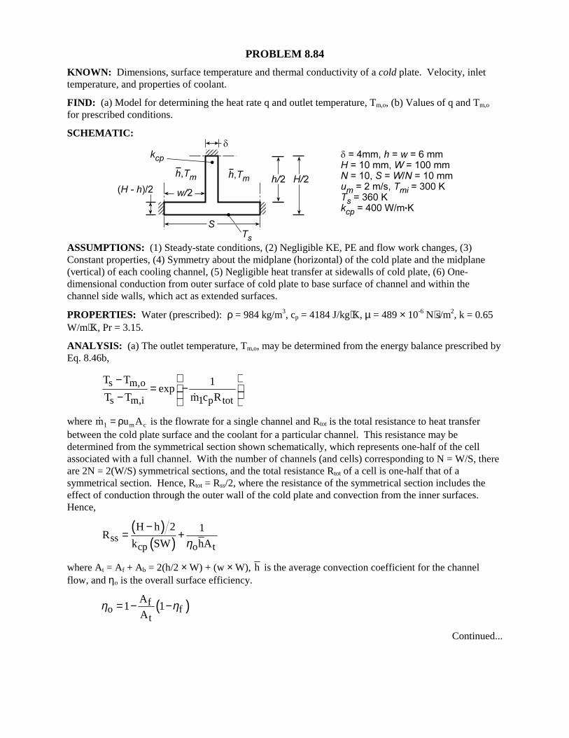
PROBLEM 8.84
KNOWN: Dimensions, surface temperature and thermal conductivity of a cold plate. Velocity, inlettemperature, and properties of coolant.
FIND: (a) Model for determining the heat rate q and outlet temperature, Tm,o, (b) Values of q and Tm,o
for prescribed conditions.
SCHEMATIC:
ASSUMPTIONS: (1) Steady-state conditions, (2) Negligible KE, PE and flow work changes, (3)Constant properties, (4) Symmetry about the midplane (horizontal) of the cold plate and the midplane(vertical) of each cooling channel, (5) Negligible heat transfer at sidewalls of cold plate, (6) One-dimensional conduction from outer surface of cold plate to base surface of channel and within thechannel side walls, which act as extended surfaces.
PROPERTIES: Water (prescribed): ρ = 984 kg/m3, cp = 4184 J/kg⋅K, µ = 489 × 10-6 N⋅s/m2, k = 0.65W/m⋅K, Pr = 3.15.
ANALYSIS: (a) The outlet temperature, Tm,o, may be determined from the energy balance prescribed byEq. 8.46b,
s m,o
s m,i 1 p tot
T T 1exp
T T m c R
−= − − �
where �m u Am c1 = ρ is the flowrate for a single channel and Rtot is the total resistance to heat transferbetween the cold plate surface and the coolant for a particular channel. This resistance may bedetermined from the symmetrical section shown schematically, which represents one-half of the cellassociated with a full channel. With the number of channels (and cells) corresponding to N = W/S, thereare 2N = 2(W/S) symmetrical sections, and the total resistance Rtot of a cell is one-half that of asymmetrical section. Hence, Rtot = Rss/2, where the resistance of the symmetrical section includes theeffect of conduction through the outer wall of the cold plate and convection from the inner surfaces.Hence,
( )( )ss
cp o t
H h 2 1R
k SW hAη−
= +
where At = Af + Ab = 2(h/2 × W) + (w × W), h is the average convection coefficient for the channelflow, and ηo is the overall surface efficiency.
( )fo f
t
A1 1
Aη η= − −
Continued...
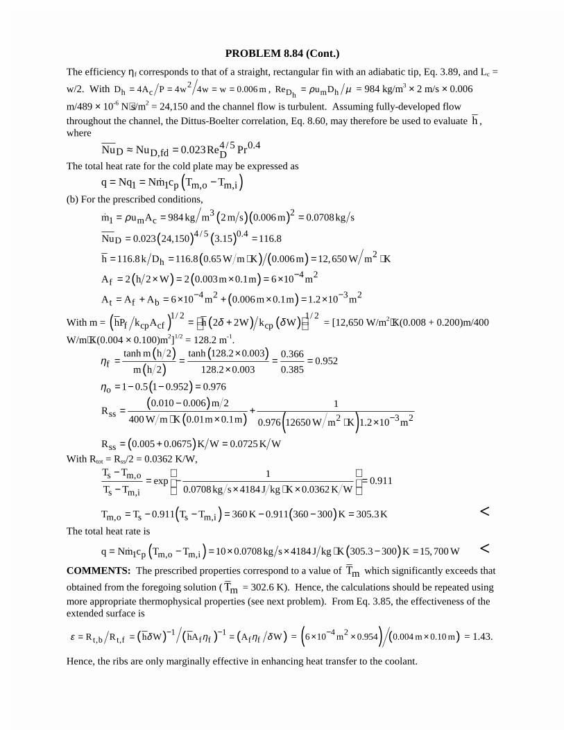
PROBLEM 8.84 (Cont.)
The efficiency ηf corresponds to that of a straight, rectangular fin with an adiabatic tip, Eq. 3.89, and Lc =
w/2. With 2h cD 4A P 4w 4w w 0.006 m= = = = ,
hD m hRe u Dρ µ= = 984 kg/m3 × 2 m/s × 0.006
m/489 × 10-6 N⋅s/m2 = 24,150 and the channel flow is turbulent. Assuming fully-developed flow
throughout the channel, the Dittus-Boelter correlation, Eq. 8.60, may therefore be used to evaluate h ,where
4 /5 0.4D D,fd DNu Nu 0.023Re Pr≈ =
The total heat rate for the cold plate may be expressed as
( )1 1 p m,o m,iq Nq Nm c T T= = −�
(b) For the prescribed conditions,
( )( )231 m cm u A 984 kg m 2 m s 0.006 m 0.0708kg sρ= = =�
( ) ( )4 / 5 0.4DNu 0.023 24,150 3.15 116.8= =
( ) ( ) 2hh 116.8 k D 116.8 0.65 W m K 0.006 m 12,650 W m K= = ⋅ = ⋅
( ) ( ) 4 2fA 2 h 2 W 2 0.003m 0.1m 6 10 m−= × = × = ×
( )4 2 3 2t f bA A A 6 10 m 0.006 m 0.1m 1.2 10 m− −= + = × + × = ×
With m = ( ) ( ) ( )1/ 2 1/ 2f cp cf cphP k A h 2 2W k Wδ δ= + = [12,650 W/m2⋅K(0.008 + 0.200)m/400
W/m⋅K(0.004 × 0.100)m2]1/2 = 128.2 m-1.( )
( )( )
ftanh m h 2 tanh 128.2 0.003 0.366
0.952m h 2 128.2 0.003 0.385
η×
= = = =×
( )o 1 0.5 1 0.952 0.976η = − − =
( )( ) ( )ss 2 3 2
0.010 0.006 m 2 1R
400 W m K 0.01m 0.1m 0.976 12650 W m K 1.2 10 m−−
= +⋅ × ⋅ ×
( )ssR 0.005 0.0675 K W 0.0725 K W= + =With Rtot = Rss/2 = 0.0362 K/W,
s m,o
s m,i
T T 1exp 0.911
T T 0.0708kg s 4184 J kg K 0.0362 K W
−= − =
− × ⋅ ×
( ) ( )m,o s s m,iT T 0.911 T T 360 K 0.911 360 300 K 305.3K= − − = − − = <The total heat rate is
( ) ( )1 p m,o m,iq Nm c T T 10 0.0708 kg s 4184 J kg K 305.3 300 K 15, 700 W= − = × × ⋅ − =� <COMMENTS: The prescribed properties correspond to a value of mT which significantly exceeds that
obtained from the foregoing solution ( mT = 302.6 K). Hence, the calculations should be repeated usingmore appropriate thermophysical properties (see next problem). From Eq. 3.85, the effectiveness of theextended surface is
( ) ( ) ( )1 1t,b t,f f f f fR R h W hA A Wε δ η η δ− −= = = = ( ) ( )4 26 10 m 0.954 0.004 m 0.10 m−× × × = 1.43.
Hence, the ribs are only marginally effective in enhancing heat transfer to the coolant.
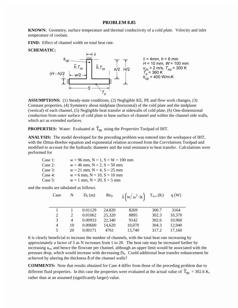
PROBLEM 8.85
KNOWN: Geometry, surface temperature and thermal conductivity of a cold plate. Velocity and inlettemperature of coolant.
FIND: Effect of channel width on total heat rate.
SCHEMATIC:
ASSUMPTIONS: (1) Steady-state conditions, (2) Negligible KE, PE and flow work changes, (3)Constant properties, (4) Symmetry about midplane (horizontal) of the cold plate and the midplane(vertical) of each channel, (5) Negligible heat transfer at sidewalls of cold plate, (6) One-dimensionalconduction from outer surface of cold plate to base surface of channel and within the channel side walls,which act as extended surfaces.
PROPERTIES: Water: Evaluated at mT using the Properties Toolpad of IHT.
ANALYSIS: The model developed for the preceding problem was entered into the workspace of IHT,with the Dittus-Boelter equation and exponential relation accessed from the Correlations Toolpad andmodified to account for the hydraulic diameter and the total resistance to heat transfer. Calculations wereperformed for
Case 1: w = 96 mm, N = 1, S = W = 100 mmCase 2: w = 46 mm, N = 2, S = 50 mmCase 3: w = 21 mm, N = 4, S = 25 mmCase 4: w = 6 mm, N = 10, S = 10 mmCase 5: w = 1 mm, N = 20, S = 5 mm
and the results are tabulated as follows.
Case N Dh (m) ReD ( )2h W m K⋅ Tm,o (K) q (W)
1 1 0.01129 24,820 8269 300.7 31642 2 0.01062 25,320 8895 302.3 10,3703 4 0.00933 22,340 9142 302.6 10,9604 10 0.00600 14,620 10,070 304.3 12,9405 20 0.00171 4761 13,740 317.2 17,160
It is clearly beneficial to increase the number of channels, with the total heat rate increasing byapproximately a factor of 5 as N increases from 1 to 20. The heat rate may be increased further byincreasing um, and hence the flowrate per channel, although an upper limit would be associated with thepressure drop, which would increase with decreasing Dh. Could additional heat transfer enhancement beachieved by altering the thickness δ of the channel walls?
COMMENTS: Note that results obtained for Case 4 differ from those of the preceding problem due to
different fluid properties. In this case the properties were evaluated at the actual value of mT = 302.6 K,rather than at an assumed (significantly larger) value.
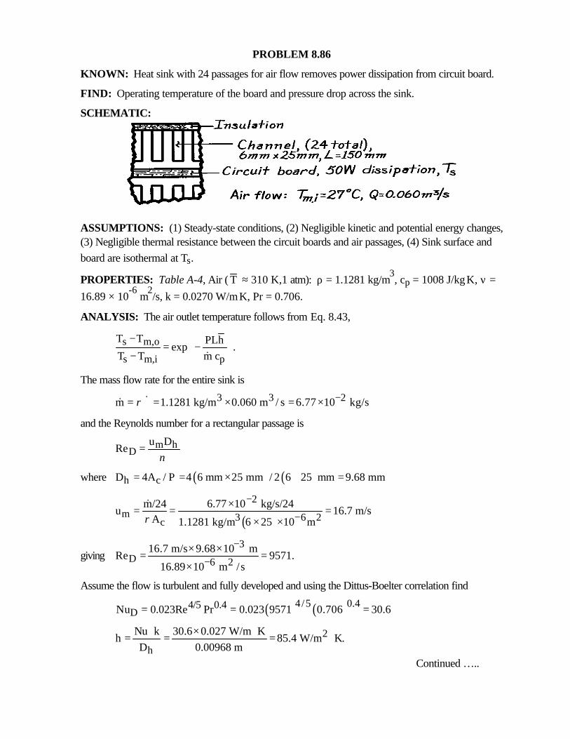
PROBLEM 8.86
KNOWN: Heat sink with 24 passages for air flow removes power dissipation from circuit board.
FIND: Operating temperature of the board and pressure drop across the sink.
SCHEMATIC:
ASSUMPTIONS: (1) Steady-state conditions, (2) Negligible kinetic and potential energy changes,(3) Negligible thermal resistance between the circuit boards and air passages, (4) Sink surface andboard are isothermal at Ts.
PROPERTIES: Table A-4, Air ( T ≈ 310 K,1 atm): ρ = 1.1281 kg/m3, cp = 1008 J/kg⋅K, ν =
16.89 × 10⁻⁶
m2/s, k = 0.0270 W/m⋅K, Pr = 0.706.
ANALYSIS: The air outlet temperature follows from Eq. 8.43,
s m,o
s m,i p
T T PLhexp .
T T m c
−= − − &
The mass flow rate for the entire sink is
3 3 2m 1.1281 kg/m 0.060 m / s 6.77 10 kg/sρ −= ∀ = × = ×&&
and the Reynolds number for a rectangular passage is
m hD
u DRe
ν=
where ( ) ( )h cD 4A / P 4 6 mm 25 mm / 2 6 25 mm 9.68 mm= = × + =
( )
2m 3 6 2c
m/24 6.77 10 kg/s/24u 16.7 m/s
A 1.1281 kg/m 6 25 10 mρ
−
−×= = =
× ×
&
giving3
D 6 216.7 m/s 9.68 10 m
Re 9571.16.89 10 m /s
−
−× ×= =×
Assume the flow is turbulent and fully developed and using the Dittus-Boelter correlation find
( ) ( )4/5 0.44/5 0.4DNu 0.023Re Pr 0.023 9571 0.706 30.6= = =
2
h
Nu k 30.6 0.027 W/m Kh 85.4 W/m K.
D 0.00968 m⋅ × ⋅= = = ⋅
Continued …..
PROBLEM 8.86 (Cont.)
From an overall energy balance on the sink,
( )p m,o m,i m,o m,i pq m c T T T =T q/m c= − +& &
2m,oT 27 C 50 W/6.77 10 kg/s 1008 J/kg K 27.73 C−= + × × ⋅ =o o
Hence, the operating temperature of the circuit board for these conditions is
( )
( )3 2
s2s 27
2 6 25 10 m 0.150m 85.4 W/m KT 27.73exp
T 6.77 10 kg/s/24 1008 J/kg K
−
−−
+ × × × ⋅− = − × × ⋅
sT 30 C.= o <The pressure drop in the rectangular passage for the smooth surface condition follows from Eqs.8.22 and 8.20
2m
h
up f L
Dρ∆ =
where
( ) 1/41/4Df 0.31Re 0.316 9554 0.0320.−= = =
( )2321.1281 kg/m 16.7 m/s
p 0.0320 0.150 m 156 N/m .0.00968 m
∆ = × = <
COMMENTS: (1) The analysis has been simplified by assuming the channel is rectangular and allfour sides experience heat transfer. Since the insulated surface is a small portion of the total passagesurface area, the effect can’t be very large.
(2) The power required to move the air through the heat sink is Pelec = ∀& ∆p = 0.060 m3/s × 156
N/m2 = 9.4 W.
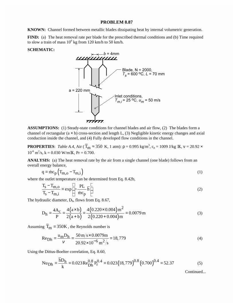
PROBLEM 8.87
KNOWN: Channel formed between metallic blades dissipating heat by internal volumetric generation.
FIND: (a) The heat removal rate per blade for the prescribed thermal conditions and (b) Time requiredto slow a train of mass 106 kg from 120 km/h to 50 km/h.
SCHEMATIC:
ASSUMPTIONS: (1) Steady-state conditions for channel blades and air flow, (2) The blades form achannel of rectangular (a × b) cross-section and length L, (3) Negligible kinetic energy changes and axialconduction inside the channel, and (4) Fully developed flow conditions in the channel.
PROPERTIES: Table A.4, Air ( mT 350≈ K, 1 atm): ρ = 0.995 kg/m3, cp = 1009 J/kg ⋅K, ν = 20.92 ×10⁻⁶ m2/s, k = 0.030 W/m⋅K, Pr = 0.700.
ANALYSIS: (a) The heat removal rate by the air from a single channel (one blade) follows from anoverall energy balance,
( )p m,o m,iq mc T T= −� (1)
where the outlet temperature can be determined from Eq. 8.42b,
s m,o
s m,i p
T T PLexp h
T T mc
−= − − �
(2)
The hydraulic diameter, Dh, flows from Eq. 8.67,
( )( )
( )( )
2c
h4 a b 4 0.220 0.004 m4A
D 0.0079 mP 2 a b 2 0.220 0.004 m
× ×= = = =
+ +(3)
Assuming mT 350K= , the Reynolds number is
m hDh 6 2
u D 50 m s 0.0079mRe 18,779
20.92 10 m sν −×= = =
×(4)
Using the Dittus-Boelter correlation, Eq. 8.60,
( ) ( )0.8 0.40.8 0.4hDh rDh
hDNu 0.023Re P 0.023 18,779 0.700 52.37
k= = = = (5)
Continued...
PROBLEM 8.87 (Cont.)
20.030 W m Kh 52.37 199 W m K
0.0079m
⋅= × = ⋅
Hence, the outlet temperature is
( )( )m,o 2600 T 2 0.220 0.004 m 0.070m
exp 199 W m K0.0438kg s 1009J kg K600 25 C
− + ×= ⋅ × ⋅ − $
m,oT 100.7 C= $
where
m� = ρAcum = 0.995 kg/m3 × (0.220 × 0.004) m2 × 50 m/s = 0.0438 kg/s
and the rate of heat removal per blade, from Eq. (1), is
( )q 0.0438kg s 1009 J kg K 100.7 25 C 3.346kW= × ⋅ − =$ <
(b) From an energy balance on the locomotive over an interval of time, ∆t, the heat energy transferred tothe air stream results in a change in kinetic energy of the train,
out f iE E KE KE− = ∆ = − (6)
( ) ( )2 2f i
1q N t M V V
2− × × ∆ = −
( ) 613346 W blade 2000blades t s 10 kg
2−− × × ∆ = ×
2 22 250,000 120,000
m s3600 3600
−
t 69s∆ = <COMMENTS: (1) For the channel, L/Dh = 0.070 m/0.0079 m = 8.9 < 10 so that the assumption of fullydeveloped conditions may not be satisfied. Recognize that the flow at the channel entrance may behighly turbulent because of the upstream fan swirl and ducting.
(2) What benefits could be realized by increasing the heat transfer coefficient? Aside from increasingvelocity, what design changes would you make to increase h?
(3) Our assumption for mT = 350 K at which to evaluate properties is reasonable considering Tm =
(100.7 + 25)°C/2 = 335 K.
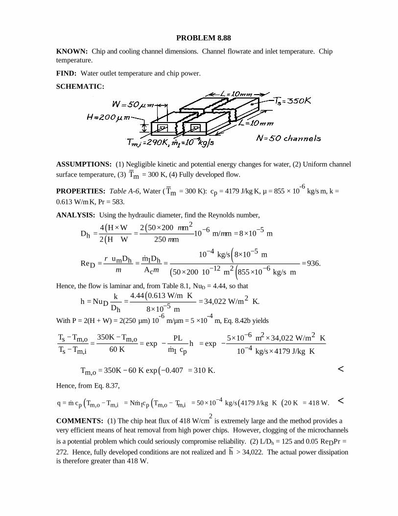
PROBLEM 8.88
KNOWN: Chip and cooling channel dimensions. Channel flowrate and inlet temperature. Chiptemperature.
FIND: Water outlet temperature and chip power.
SCHEMATIC:
ASSUMPTIONS: (1) Negligible kinetic and potential energy changes for water, (2) Uniform channelsurface temperature, (3) mT = 300 K, (4) Fully developed flow.
PROPERTIES: Table A-6, Water ( mT = 300 K): cp = 4179 J/kg⋅K, µ = 855 × 10-6
kg/s⋅m, k =0.613 W/m⋅K, Pr = 583.
ANALYSIS: Using the hydraulic diameter, find the Reynolds number,
( )( )
( ) 26 5
h4 H W 2 50 200 m
D 10 m/ m 8 10 m2 H W 250 m
µµ
µ− −× ×
= = = ×+
( )( ) ( )
4 5m h 1 h
D 12 2 6c
10 kg/s 8 10 m u D m DRe 936.
A 50 200 10 m 855 10 kg/s m
ρµ µ
− −
− −
×= = = =
× × ⋅
&
Hence, the flow is laminar and, from Table 8.1, NuD = 4.44, so that( ) 2
D 5h
4.44 0.613 W/m Kkh Nu 34,022 W/m K.
D 8 10 m−⋅
= = = ⋅×
With P = 2(H + W) = 2(250 µm) 10-6
m/µm = 5 ×10⁻⁴
m, Eq. 8.42b yields
6 2 2s m,o m,o
4s m,i 1 p
T T 350K T PL 5 10 m 34,022 W/m Kexp h exp
T T 60 K m c 10 kg/s 4179 J/kg K
−
−
− − × × ⋅ = = − = − − × ⋅ &
( )m,oT 350K 60 K exp 0.407 310 K.= − − = <Hence, from Eq. 8.37,
( ) ( ) ( ) ( )4p m,o m,i 1 p m,o m,iq m c T T Nm c T T 50 10 kg/s 4179 J/kg K 20 K 418 W.−= − = − = × ⋅ =& & <
COMMENTS: (1) The chip heat flux of 418 W/cm2 is extremely large and the method provides a
very efficient means of heat removal from high power chips. However, clogging of the microchannels
is a potential problem which could seriously compromise reliability. (2) L/Dh = 125 and 0.05 ReDPr =272. Hence, fully developed conditions are not realized and h > 34,022. The actual power dissipationis therefore greater than 418 W.
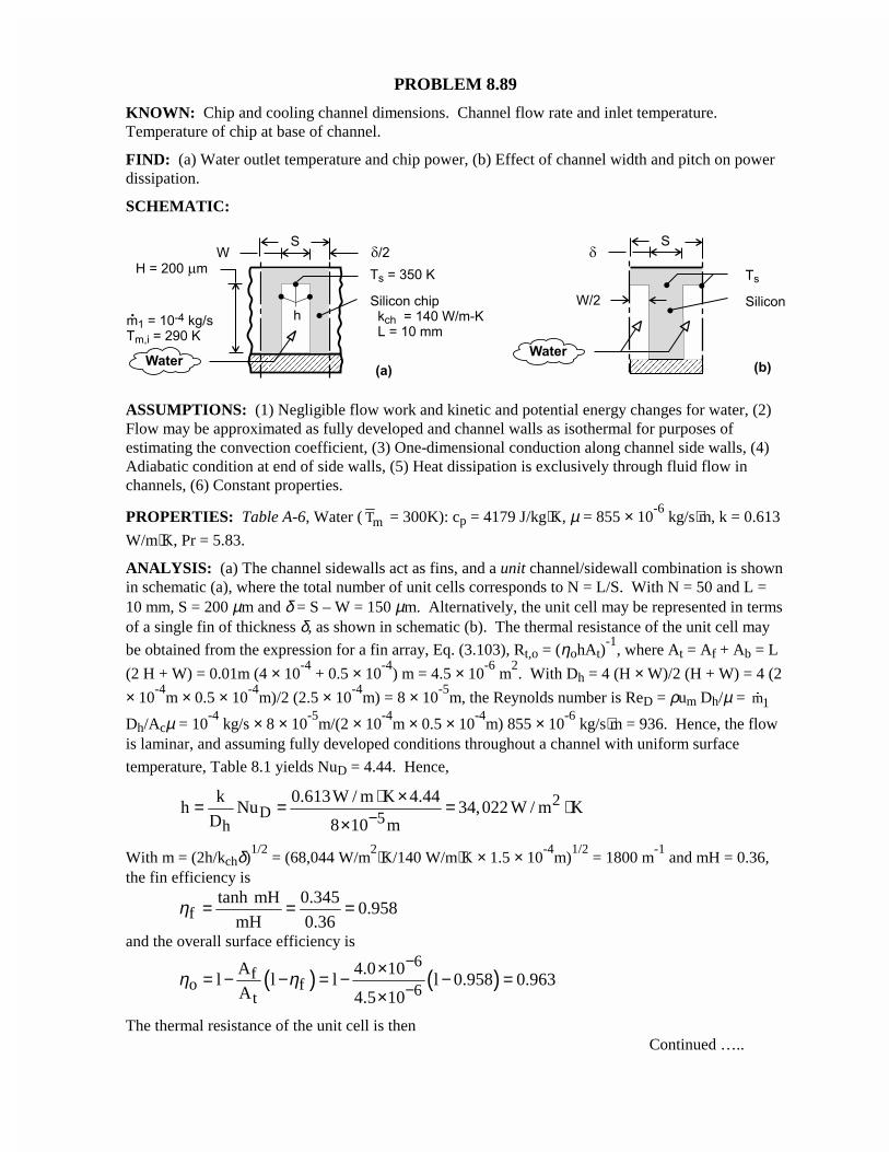
PROBLEM 8.89
KNOWN: Chip and cooling channel dimensions. Channel flow rate and inlet temperature.Temperature of chip at base of channel.
FIND: (a) Water outlet temperature and chip power, (b) Effect of channel width and pitch on powerdissipation.
SCHEMATIC:
ASSUMPTIONS: (1) Negligible flow work and kinetic and potential energy changes for water, (2)Flow may be approximated as fully developed and channel walls as isothermal for purposes ofestimating the convection coefficient, (3) One-dimensional conduction along channel side walls, (4)Adiabatic condition at end of side walls, (5) Heat dissipation is exclusively through fluid flow inchannels, (6) Constant properties.
PROPERTIES: Table A-6, Water ( mT = 300K): cp = 4179 J/kg⋅K, µ = 855 × 10-6
kg/s⋅m, k = 0.613
W/m⋅K, Pr = 5.83.
ANALYSIS: (a) The channel sidewalls act as fins, and a unit channel/sidewall combination is shownin schematic (a), where the total number of unit cells corresponds to N = L/S. With N = 50 and L =10 mm, S = 200 µm and δ = S – W = 150 µm. Alternatively, the unit cell may be represented in termsof a single fin of thickness δ, as shown in schematic (b). The thermal resistance of the unit cell may
be obtained from the expression for a fin array, Eq. (3.103), Rt,o = (ηohAt)-1
, where At = Af + Ab = L
(2 H + W) = 0.01m (4 × 10⁻⁴
+ 0.5 × 10⁻⁴
) m = 4.5 × 10⁻⁶
m2. With Dh = 4 (H × W)/2 (H + W) = 4 (2
× 10-4
m × 0.5 × 10-4
m)/2 (2.5 × 10⁻⁴
m) = 8 × 10⁻⁵
m, the Reynolds number is ReD = ρum Dh/µ = 1m�
Dh/Acµ = 10-4
kg/s × 8 × 10⁻⁵
m/(2 × 10-4
m × 0.5 × 10-4
m) 855 × 10-6
kg/s⋅m = 936. Hence, the flowis laminar, and assuming fully developed conditions throughout a channel with uniform surface
temperature, Table 8.1 yields NuD = 4.44. Hence,
2D 5h
k 0.613W / m K 4.44h Nu 34,022 W / m K
D 8 10 m−⋅ ×= = = ⋅
×
With m = (2h/kchδ)1/2
= (68,044 W/m2⋅K/140 W/m⋅K × 1.5 × 10
-4m)
1/2 = 1800 m
-1 and mH = 0.36,
the fin efficiency is
ftanh mH 0.345
0.958mH 0.36
η = = =
and the overall surface efficiency is
( ) ( )6
fo f 6t
A 4.0 10l l l l 0.958 0.963
A 4.5 10η η
−
−×= − − = − − =×
The thermal resistance of the unit cell is thenContinued …..
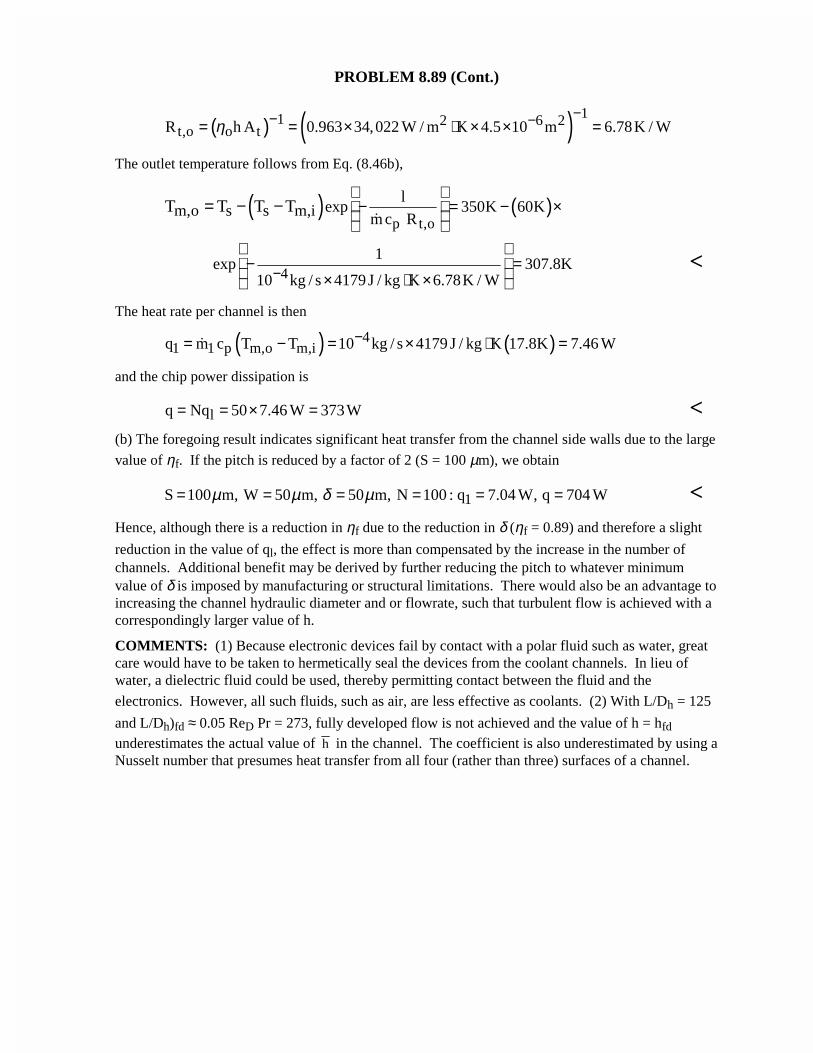
PROBLEM 8.89 (Cont.)
( ) ( ) 11 2 6 2t,o o tR h A 0.963 34,022 W / m K 4.5 10 m 6.78K / Wη
−− −= = × ⋅ × × =
The outlet temperature follows from Eq. (8.46b),
( ) ( )p t,o
lexp 350K 60Km,o s s m,i m c R
T T T T − = − ×
= − −�
41
exp 307.8K10 kg / s 4179J / kg K 6.78K / W−
− = × ⋅ ×
<
The heat rate per channel is then
( ) ( )41 1 p m,o m,iq m c T T 10 kg / s 4179 J / kg K 17.8K 7.46 W−= − = × ⋅ =�
and the chip power dissipation is
lq Nq 50 7.46 W 373W= = × = <(b) The foregoing result indicates significant heat transfer from the channel side walls due to the large
value of ηf. If the pitch is reduced by a factor of 2 (S = 100 µm), we obtain
1S 100 m, W 50 m, 50 m, N 100 : q 7.04 W, q 704 Wµ µ δ µ= = = = = = <Hence, although there is a reduction in ηf due to the reduction in δ (ηf = 0.89) and therefore a slight
reduction in the value of ql, the effect is more than compensated by the increase in the number ofchannels. Additional benefit may be derived by further reducing the pitch to whatever minimumvalue of δ is imposed by manufacturing or structural limitations. There would also be an advantage toincreasing the channel hydraulic diameter and or flowrate, such that turbulent flow is achieved with acorrespondingly larger value of h.
COMMENTS: (1) Because electronic devices fail by contact with a polar fluid such as water, greatcare would have to be taken to hermetically seal the devices from the coolant channels. In lieu ofwater, a dielectric fluid could be used, thereby permitting contact between the fluid and the
electronics. However, all such fluids, such as air, are less effective as coolants. (2) With L/Dh = 125
and L/Dh)fd ≈ 0.05 ReD Pr = 273, fully developed flow is not achieved and the value of h = hfd
underestimates the actual value of h in the channel. The coefficient is also underestimated by using aNusselt number that presumes heat transfer from all four (rather than three) surfaces of a channel.
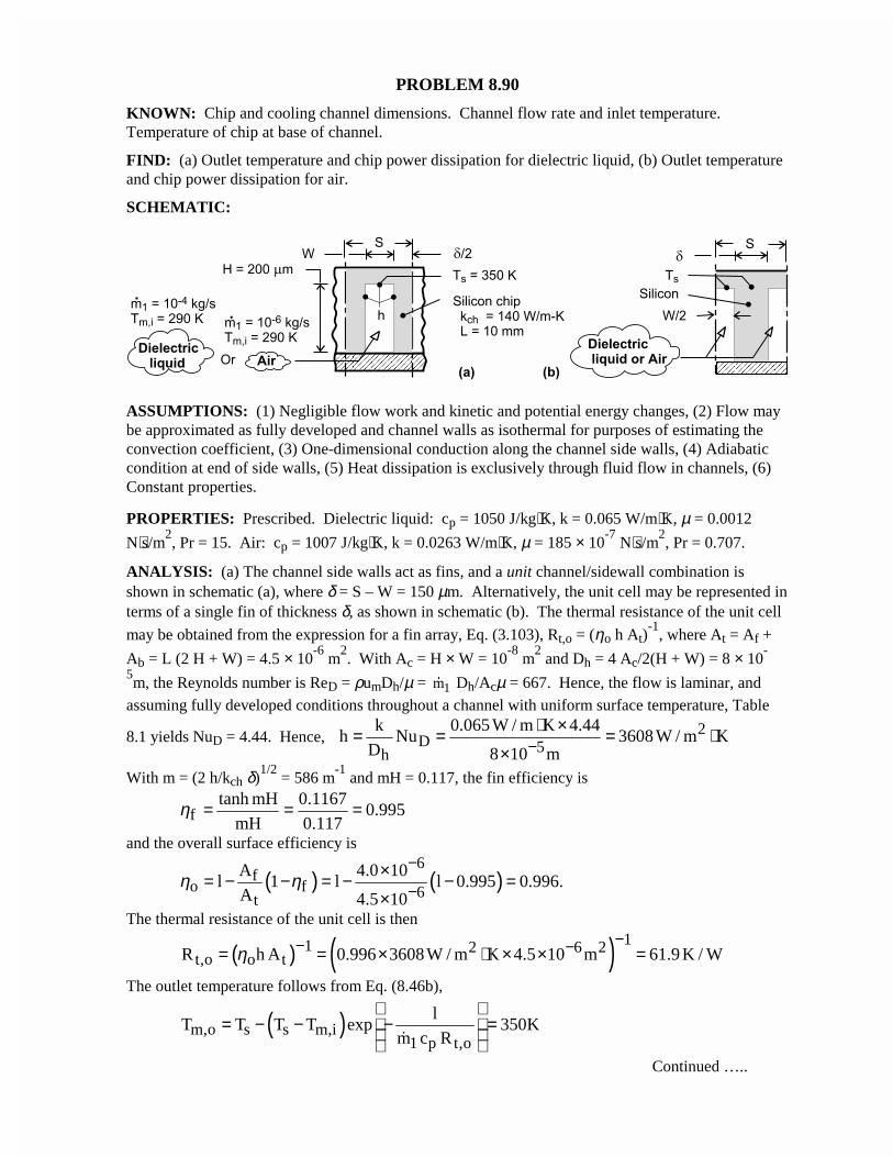
PROBLEM 8.90
KNOWN: Chip and cooling channel dimensions. Channel flow rate and inlet temperature.Temperature of chip at base of channel.
FIND: (a) Outlet temperature and chip power dissipation for dielectric liquid, (b) Outlet temperatureand chip power dissipation for air.
SCHEMATIC:
ASSUMPTIONS: (1) Negligible flow work and kinetic and potential energy changes, (2) Flow maybe approximated as fully developed and channel walls as isothermal for purposes of estimating theconvection coefficient, (3) One-dimensional conduction along the channel side walls, (4) Adiabaticcondition at end of side walls, (5) Heat dissipation is exclusively through fluid flow in channels, (6)Constant properties.
PROPERTIES: Prescribed. Dielectric liquid: cp = 1050 J/kg⋅K, k = 0.065 W/m⋅K, µ = 0.0012
N⋅s/m2, Pr = 15. Air: cp = 1007 J/kg⋅K, k = 0.0263 W/m⋅K, µ = 185 × 10
-7 N⋅s/m
2, Pr = 0.707.
ANALYSIS: (a) The channel side walls act as fins, and a unit channel/sidewall combination isshown in schematic (a), where δ = S – W = 150 µm. Alternatively, the unit cell may be represented interms of a single fin of thickness δ, as shown in schematic (b). The thermal resistance of the unit cell
may be obtained from the expression for a fin array, Eq. (3.103), Rt,o = (ηo h At)-1
, where At = Af +
Ab = L (2 H + W) = 4.5 × 10⁻⁶
m2. With Ac = H × W = 10
-8 m
2 and Dh = 4 Ac/2(H + W) = 8 × 10
-
5m, the Reynolds number is ReD = ρumDh/µ = 1m� Dh/Acµ = 667. Hence, the flow is laminar, and
assuming fully developed conditions throughout a channel with uniform surface temperature, Table
8.1 yields NuD = 4.44. Hence, 2D 5h
k 0.065 W / m K 4.44h Nu 3608 W / m K
D 8 10 m−⋅ ×= = = ⋅
×With m = (2 h/kch δ)
1/2 = 586 m
-1 and mH = 0.117, the fin efficiency is
ftanh mH 0.1167
0.995mH 0.117
η = = =
and the overall surface efficiency is
( ) ( )6
fo f 6t
A 4.0 10l 1 l l 0.995 0.996.
A 4.5 10η η
−
−×= − − = − − =×
The thermal resistance of the unit cell is then
( ) ( ) 11 2 6 2t,o o tR h A 0.996 3608W / m K 4.5 10 m 61.9 K / Wη
−− −= = × ⋅ × × =
The outlet temperature follows from Eq. (8.46b),
( )m,o s s m,i1 p t,o
lT T T T exp 350K
m c R
= − − − = �
Continued …..
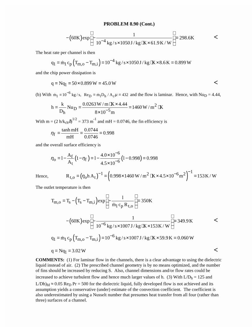
PROBLEM 8.90 (Cont.)
( ) 41
60K exp 298.6K10 kg / s 1050J / kg K 61.9K / W−
− − = × ⋅ ×
<
The heat rate per channel is then
( ) 41 1 p m,o m,iq m c T T 10 kg / s 1050J / kg K 8.6 K 0.899 W−= − = × ⋅ × =�
and the chip power dissipation is
1q Nq 50 0.899 W 45.0 W= = × = <
(b) With 61m 10 kg / s,−=� D l h cRe m D / A 432µ= =� and the flow is laminar. Hence, with NuD = 4.44,
2D 5h
k 0.0263W / m K 4.44h Nu 1460 W / m K
D 8 10 m−⋅ ×= = = ⋅
×
With m = (2 h/kchδ)1/2
= 373 m-1
and mH = 0.0746, the fin efficiency is
ftanh mH 0.0744
0.998mH 0.0746
η = = =
and the overall surface efficiency is
( ) ( )6
fo f 6t
A 4.0 10l 1 l l 0.998 0.998
A 4.5 10η η
−
−×= − − = − − =×
Hence, ( ) ( ) 11 2 6 2t,o o tR h A 0.998 1460 W / m K 4.5 10 m 153K / Wη
−− −= = × ⋅ × × =
The outlet temperature is then
( )m,o s s m,i1 p t,o
lT T T T exp 350K
m c R
= − − − = �
( ) 61
60K exp 349.9 K10 kg / s 1007 J / kg K 153K / W−
− − = × ⋅ ×
<
( ) 61 1 p m,o m,iq m c T T 10 kg / s 1007 J / kg K 59.9 K 0.060 W−= − = × ⋅ × =�
1q Nq 3.02 W= = <COMMENTS: (1) For laminar flow in the channels, there is a clear advantage to using the dielectricliquid instead of air. (2) The prescribed channel geometry is by no means optimized, and the numberof fins should be increased by reducing S. Also, channel dimensions and/or flow rates could be
increased to achieve turbulent flow and hence much larger values of h. (3) With L/Dh = 125 and
L/Dh)fd ≈ 0.05 ReD Pr = 500 for the dielectric liquid, fully developed flow is not achieved and itsassumption yields a conservative (under) estimate of the convection coefficient. The coefficient isalso underestimated by using a Nusselt number that presumes heat transfer from all four (rather thanthree) surfaces of a channel.
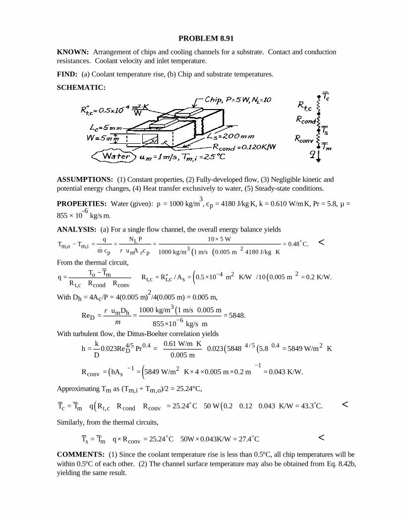
PROBLEM 8.91
KNOWN: Arrangement of chips and cooling channels for a substrate. Contact and conductionresistances. Coolant velocity and inlet temperature.
FIND: (a) Coolant temperature rise, (b) Chip and substrate temperatures.
SCHEMATIC:
ASSUMPTIONS: (1) Constant properties, (2) Fully-developed flow, (3) Negligible kinetic andpotential energy changes, (4) Heat transfer exclusively to water, (5) Steady-state conditions.
PROPERTIES: Water (given): ρ = 1000 kg/m3, cp = 4180 J/kg⋅K, k = 0.610 W/m⋅K, Pr = 5.8, µ =
855 × 10-6
kg/s⋅m.
ANALYSIS: (a) For a single flow channel, the overall energy balance yields
( )( )L
m,o m,i 3 2p m c p
q N P 10 5 WT T 0.48 C.
m c u A c 1000 kg/m 1 m/s 0.005 m 4180 J/kg Kρ
×− = = = =
⋅
o
&<
From the thermal circuit,
( ) ( )24 2o mt,c t,c s
t,c cond conv
T Tq R R / A 0.5 10 m K/W /10 0.005 m 0.2 K/W.
R R R−− ′′= = = × ⋅ =
+ +
With Dh = 4Ac/P = 4(0.005 m)2/4(0.005 m) = 0.005 m,
( )3m h
D 6
1000 kg/m 1 m/s 0.005 m u DRe 5848.
855 10 kg/s m
ρµ −
= = =× ⋅
With turbulent flow, the Dittus-Boelter correlation yields
( ) ( )4 / 5 0.44/5 0.4 2D
k 0.61 W/m Kh 0.023Re Pr 0.023 5848 5.8 5849 W/m K
D 0.005 m
⋅= = = ⋅
( ) ( ) 11 2conv sR hA 5849 W/m K 4 0.005 m 0.2 m 0.043 K/W.
−−= = ⋅ × × × =
Approximating Tm as (Tm,i + Tm,o)/2 = 25.24°C,
( ) ( )c m t,c cond convT T q R R R 25.24 C 50 W 0.2 0.12 0.043 K/W 43.3 C.= + + + = + + + =o o <Similarly, from the thermal circuits,
s m convT T q R 25.24 C 50W 0.043K/W 27.4 C= + × = + × =o o <COMMENTS: (1) Since the coolant temperature rise is less than 0.5°C, all chip temperatures will bewithin 0.5°C of each other. (2) The channel surface temperature may also be obtained from Eq. 8.42b,yielding the same result.
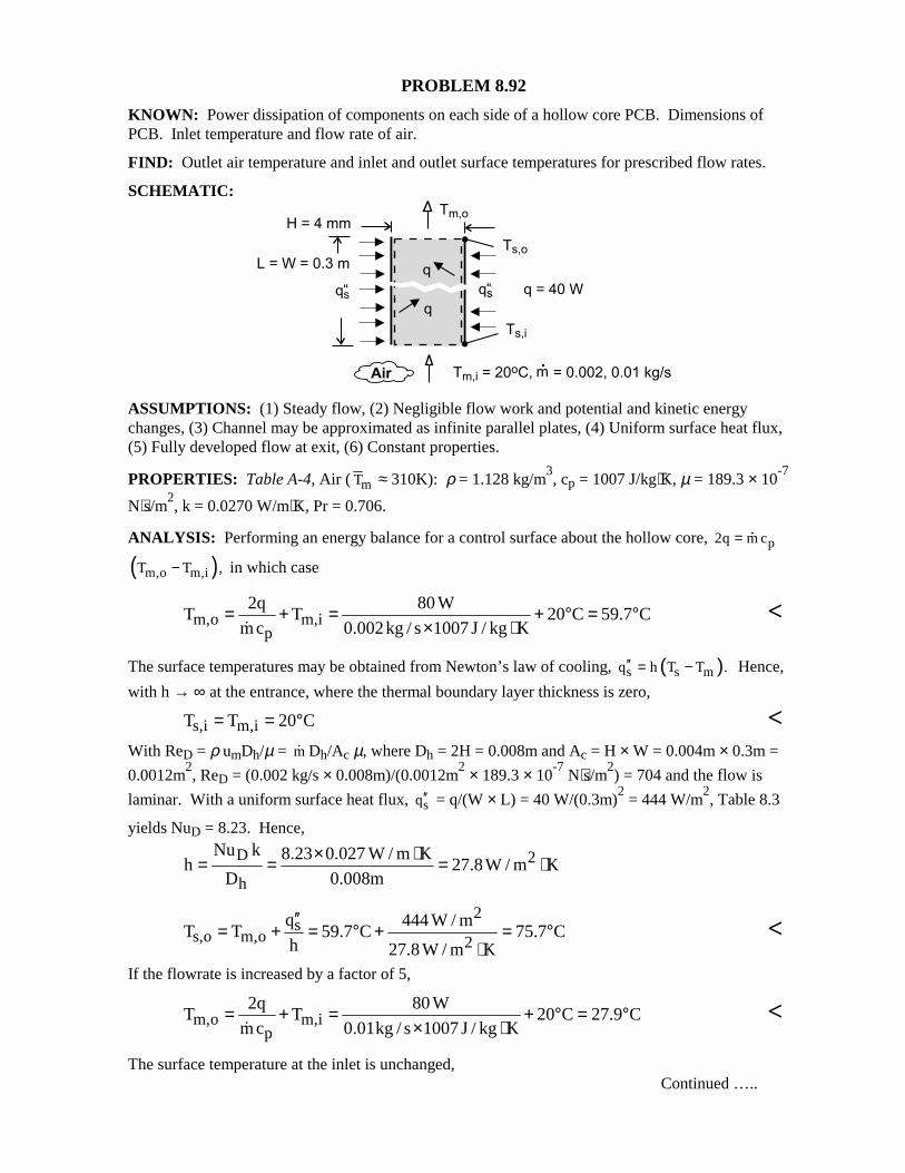
PROBLEM 8.92
KNOWN: Power dissipation of components on each side of a hollow core PCB. Dimensions ofPCB. Inlet temperature and flow rate of air.
FIND: Outlet air temperature and inlet and outlet surface temperatures for prescribed flow rates.
SCHEMATIC:
ASSUMPTIONS: (1) Steady flow, (2) Negligible flow work and potential and kinetic energychanges, (3) Channel may be approximated as infinite parallel plates, (4) Uniform surface heat flux,(5) Fully developed flow at exit, (6) Constant properties.
PROPERTIES: Table A-4, Air ( mT ≈ 310K): ρ = 1.128 kg/m3, cp = 1007 J/kg⋅K, µ = 189.3 × 10
-7
N⋅s/m2, k = 0.0270 W/m⋅K, Pr = 0.706.
ANALYSIS: Performing an energy balance for a control surface about the hollow core, p2q m c= �
( )m,o m,iT T ,− in which case
m,o m,ip
2q 80 WT T 20 C 59.7 C
m c 0.002kg / s 1007 J / kg K= + = + ° = °
× ⋅�<
The surface temperatures may be obtained from Newton’s law of cooling, ( )s s mq h T T .′′ = − Hence,
with h → ∞ at the entrance, where the thermal boundary layer thickness is zero,
s,i m,iT T 20 C= = ° <With ReD = ρ umDh/µ = m� Dh/Ac µ, where Dh = 2H = 0.008m and Ac = H × W = 0.004m × 0.3m =
0.0012m2, ReD = (0.002 kg/s × 0.008m)/(0.0012m
2 × 189.3 × 10
-7 N⋅s/m
2) = 704 and the flow is
laminar. With a uniform surface heat flux, sq′′ = q/(W × L) = 40 W/(0.3m)2 = 444 W/m
2, Table 8.3
yields NuD = 8.23. Hence,
D 2
h
Nu k 8.23 0.027 W / m Kh 27.8W / m K
D 0.008m
× ⋅= = = ⋅
2s
s,o m,o 2q 444 W / m
T T 59.7 C 75.7 Ch 27.8 W / m K
′′= + = ° + = °
⋅<
If the flowrate is increased by a factor of 5,
m,o m,ip
2q 80 WT T 20 C 27.9 C
m c 0.01kg / s 1007 J / kg K= + = + ° = °
× ⋅�<
The surface temperature at the inlet is unchanged,Continued …..
PROBLEM 8.92 (Cont.)
s,iT 20 C= ° <but with ReD = 3520, flow in the channel is now turbulent. Using Eq. (8.60) as a first approximation,
( ) ( )4 / 5 0.44 / 5 0.4 2D
h
k 0.027 W / m Kh 0.023Re Pr 0.023 3520 0.706 46.4 W / m K
D 0.008m
⋅= = = ⋅
2s
s,o m,o 2q 444 W / m
T T 27.9 C 37.5 Ch 46.4 W / m K
′′= + = ° + = °
⋅<
COMMENTS: (1) With L/Dh = 37.5 and L/Dh)fd ≈ 0.05 ReD Pr = 25 for the laminar flow, it isreasonable to assume fully developed conditions at the exit. The same may be said for the turbulent
flow condition. (2) The temperature difference, Ts – Tm, increases from approximately 0 at theentrance to a maximum value associated with fully developed conditions.
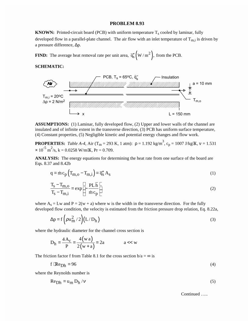
PROBLEM 8.93
KNOWN: Printed-circuit board (PCB) with uniform temperature Ts cooled by laminar, fully
developed flow in a parallel-plate channel. The air flow with an inlet temperature of Tm,i is driven bya pressure difference, ∆p.
FIND: The average heat removal rate per unit area, ( )2sq W / m ,′′ from the PCB.
SCHEMATIC:
ASSUMPTIONS: (1) Laminar, fully developed flow, (2) Upper and lower walls of the channel areinsulated and of infinite extent in the transverse direction, (3) PCB has uniform surface temperature,(4) Constant properties, (5) Negligible kinetic and potential energy changes and flow work.
PROPERTIES: Table A-4, Air (Tm = 293 K, 1 atm): ρ = 1.192 kg/m3, cp = 1007 J/kg⋅K, ν = 1.531
× 10-5
m2/s, k = 0.0258 W/m⋅K, Pr = 0.709.
ANALYSIS: The energy equations for determining the heat rate from one surface of the board areEqs. 8.37 and 8.42b
( )p m,o m,i s sq m c T T q A′′= − =� (1)
s m,o
s m,i p
T T PL hexp
T T m c
−= − − �
(2)
where As = Lw and P = 2(w + a) where w is the width in the transverse direction. For the fullydeveloped flow condition, the velocity is estimated from the friction pressure drop relation, Eq. 8.22a,
( )( )2m hp f u / 2 L / Dρ∆ = (3)
where the hydraulic diameter for the channel cross section is
( )( )
ch
4 w a4 AD 2a a w
P 2 w a= = = <<
+
The friction factor f from Table 8.1 for the cross section b/a = ∞ is
Dhf Re 96⋅ = (4)
where the Reynolds number is
Dh m hRe u D /ν= (5)
Continued …..
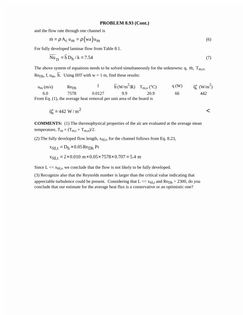
PROBLEM 8.93 (Cont.)
and the flow rate through one channel is
( )c m mm A u wa uρ ρ= =� (6)
For fully developed laminar flow from Table 8.1.
D hNu h D / k 7.54= = (7)
The above system of equations needs to be solved simultaneously for the unknowns: q, m,� Tm,o,
ReDh, f, um, h. Using IHT with w = 1 m, find these results:
um (m/s) ReDh f h (W/m2⋅K) Tm,o (°C) q (W)
sq′′ (W/m2)
6.0 7578 0.0127 9.9 20.9 66 442From Eq. (1), the average heat removal per unit area of the board is
2sq 442 W / m′′ = <
COMMENTS: (1) The thermophysical properties of the air are evaluated at the average mean
temperature, Tm = (Tm,i + Tm,o)/2.
(2) The fully developed flow length, xfd,t, for the channel follows from Eq. 8.23,
fd,t h Dhx D 0.05Re Pr= ×
fd,tx 2 0.010 m 0.05 7578 0.707 5.4 m= × × × × =
Since L << xfd,t, we conclude that the flow is not likely to be fully developed.
(3) Recognize also that the Reynolds number is larger than the critical value indicating that
appreciable turbulence could be present. Considering that L << xfd,t and ReDh > 2300, do youconclude that our estimate for the average heat flux is a conservative or an optimistic one?
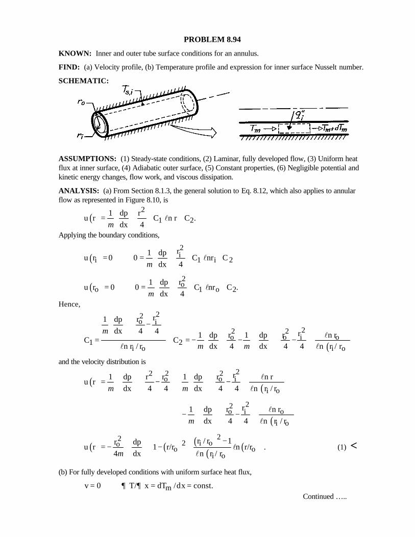
PROBLEM 8.94
KNOWN: Inner and outer tube surface conditions for an annulus.
FIND: (a) Velocity profile, (b) Temperature profile and expression for inner surface Nusselt number.
SCHEMATIC:
ASSUMPTIONS: (1) Steady-state conditions, (2) Laminar, fully developed flow, (3) Uniform heatflux at inner surface, (4) Adiabatic outer surface, (5) Constant properties, (6) Negligible potential andkinetic energy changes, flow work, and viscous dissipation.
ANALYSIS: (a) From Section 8.1.3, the general solution to Eq. 8.12, which also applies to annularflow as represented in Figure 8.10, is
( )2
1 21 dp r
u r C n r C .dx 4µ
= + + l
Applying the boundary conditions,
( )2i
i 1 i 2r1 dp
u r 0 0 C nr Cdx 4µ
= = + + l
( )2o
o 1 o 2r1 dp
u r 0 0 C nr C .dx 4µ
= = + + l
Hence,
( )
22o i
22 2o o oi
1 2i o i o
rr1 dp
dx 4 4 rr r n r1 dp 1 dpC C
n r / r dx 4 dx 4 4 n r / r
µ
µ µ
− = = − − −
l
l l
and the velocity distribution is
( ) ( )
22 22o o i
i o
rr r1 dp r 1 dp n ru r
dx 4 4 dx 4 4 n r / rµ µ
= − + −
l
l
( )
22o oi
i o
rr n r1 dp
dx 4 4 n r / rµ
− −
l
l
( ) ( ) ( )( ) ( )
222 i oo
o oi o
r / r 1r dpu r 1 r/r n r/r .
4 dx n r / rµ
− = − − + l
l (1) <
(b) For fully developed conditions with uniform surface heat flux,
mv 0 T/ x dT /dx const.∂ ∂= = =Continued …..
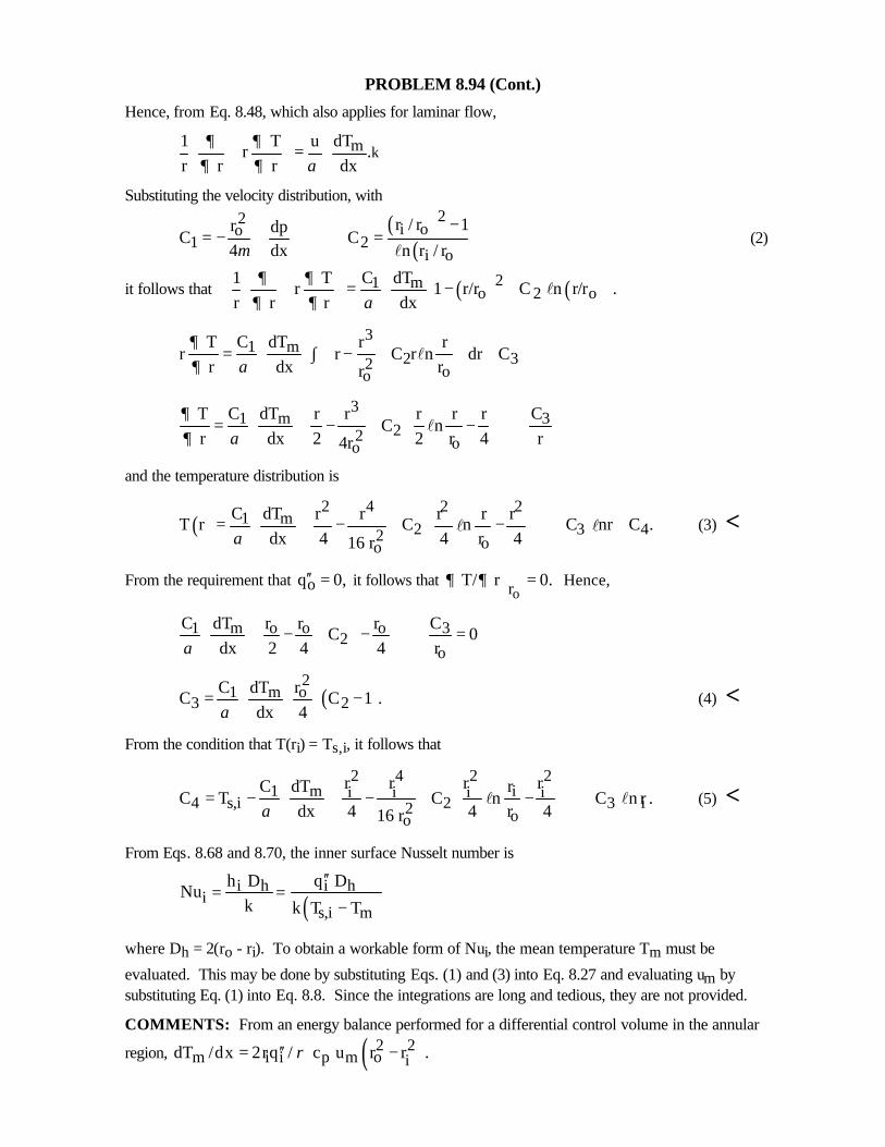
PROBLEM 8.94 (Cont.)
Hence, from Eq. 8.48, which also applies for laminar flow,
m1 T u dT r .
r r r dx∂ ∂
∂ ∂ α =
k
Substituting the velocity distribution, with
( )( )
22i oo
1 2i o
r / r 1r dpC C
4 dx n r / rµ− = − = l
(2)
it follows that ( ) ( )21 mo 2 o
1 T C dT r 1 r/r C n r/r .
r r r dx∂ ∂
∂ ∂ α = − +
l
31 m
2 32 oo
T C dT r rr r C r n dr C
r dx rr
∂∂ α
= ∫ − + +
l
331 m
22 oo
C T C dT r r r r r C n
r dx 2 2 r 4 r4r
∂∂ α
= − + − +
l
and the temperature distribution is
( )2 4 2 2
1 m2 3 42 oo
C dT r r r r rT r C n C nr C .
dx 4 4 r 416 rα
= − + − + +
l l (3) <
From the requirement that oq 0,′′ = it follows that )or
T/ r 0.∂ ∂ = Hence,
o o o 31 m2
o
r r r CC dT C 0
dx 2 4 4 rα − + − + =
( )2o1 m
3 2rC dT
C C 1 .dx 4α
= − (4) <
From the condition that T(ri) = Ts,i, it follows that
2 4 2 21 m ii i i i
4 s,i 2 3 i2 oo
r r r rC dT rC T C n C n r .
dx 4 4 r 416 rα
= − − + − +
l l (5) <
From Eqs. 8.68 and 8.70, the inner surface Nusselt number is
( )i h i h
is,i m
h D q DNu
k k T T
′′= =
−
where Dh = 2(ro - ri). To obtain a workable form of Nui, the mean temperature Tm must be
evaluated. This may be done by substituting Eqs. (1) and (3) into Eq. 8.27 and evaluating um bysubstituting Eq. (1) into Eq. 8.8. Since the integrations are long and tedious, they are not provided.
COMMENTS: From an energy balance performed for a differential control volume in the annular
region, ( )2 2m i i p m o idT /dx 2rq / c u r r .ρ′′= −
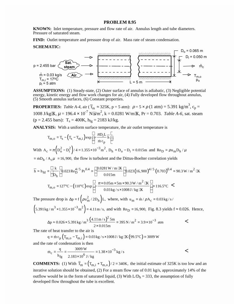
PROBLEM 8.95KNOWN: Inlet temperature, pressure and flow rate of air. Annulus length and tube diameters.Pressure of saturated steam.
FIND: Outlet temperature and pressure drop of air. Mass rate of steam condensation.
SCHEMATIC:
ASSUMPTIONS: (1) Steady-state, (2) Outer surface of annulus is adiabatic, (3) Negligible potentialenergy, kinetic energy and flow work changes for air, (4) Fully developed flow throughout annulus,(5) Smooth annulus surfaces, (6) Constant properties.
PROPERTIES: Table A-4, air ( mT ≈ 325K, p = 5 atm): ρ = 5 × ρ (1 atm) = 5.391 kg/m3, cp =
1008 J/kg⋅K, µ = 196.4 × 10⁻⁷ N⋅s/m2, k = 0.0281 W/m⋅K, Pr = 0.703. Table A-6, sat. steam(p = 2.455 bars): Ts = 400K, hfg = 2183 kJ/kg.
ANALYSIS: With a uniform surface temperature, the air outlet temperature is
( ) im,o s s m,i
p
D LT T T T exp h
m c
π= − − −
�
With ( )2 2 3 2c o i h o iA D D / 4 1.355 10 m , D D D 0.015mπ −= − = × = − = and D m hRe u D /ρ µ=
h cmD / A µ= � 16, 900,= the flow is turbulent and the Dittus-Boelter correlation yields
( ) ( )4 / 5 0.4 24 / 5 0.4fd D
h
k 0.0281W / m Kh h 0.023 Re Pr 0.023 16, 900 0.703 90.3 W / m K
D 0.015m
⋅≈ = = = ⋅
( )2
m,o0.05m 5m 90.3 W / m K
T 127 C 110 C exp 116.5 C0.03 kg / s 1008 J / kg K
π × × × ⋅= ° − ° − = °
× ⋅
<
The pressure drop is ( )2m hp f u / 2D L,ρ∆ = where, with m cu m / A 0.03 kg / s /ρ= =�
( )3 3 25.391kg / m 1.355 10 m 4.11m / s,−× × = and with DRe 16,900,= Fig. 8.3 yields f ≈ 0.026. Hence,
( )23 2 34.11m / s 5m
p 0.026 5.391kg / m 395 N / m 3.9 10 atm2 0.015m
−∆ ≈ × = = ××
<The rate of heat transfer to the air is
( ) ( )p m,o m,iq m c T T 0.03 kg / s 1008 J / kg K 99.5 C 3009 W= − = × ⋅ ° =�
and the rate of condensation is then
3c 6
fg
q 3009 Wm 1.38 10 kg / s
h 2.183 10 J / kg
−= = = ××
� <
COMMENTS: (1) With ( )m m,i m,oT T T / 2 340K,= + = the initial estimate of 325K is too low and an
iterative solution should be obtained, (2) For a steam flow rate of 0.01 kg/s, approximately 14% of the
outflow would be in the form of saturated liquid, (3) With L/Dh = 333, the assumption of fullydeveloped flow throughout the tube is excellent.
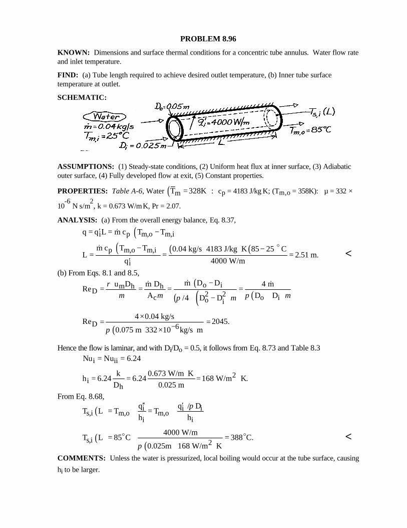
PROBLEM 8.96
KNOWN: Dimensions and surface thermal conditions for a concentric tube annulus. Water flow rateand inlet temperature.
FIND: (a) Tube length required to achieve desired outlet temperature, (b) Inner tube surfacetemperature at outlet.
SCHEMATIC:
ASSUMPTIONS: (1) Steady-state conditions, (2) Uniform heat flux at inner surface, (3) Adiabaticouter surface, (4) Fully developed flow at exit, (5) Constant properties.
PROPERTIES: Table A-6, Water ( )mT 328K := cp = 4183 J/kg⋅K; (Tm,o = 358K): µ = 332 ×
10-6
N⋅s/m2, k = 0.673 W/m⋅K, Pr = 2.07.
ANALYSIS: (a) From the overall energy balance, Eq. 8.37,
( )i p m,o m,iq q L m c T T′= = −&
( ) ( ) ( )p m,o m,i
i
m c T T 0.04 kg/s 4183 J/kg K 85 25 CL 2.51 m.
q 4000 W/m
− ⋅ −= = =
′
o&<
(b) From Eqs. 8.1 and 8.5,( )
( ) ( ) ( )o im h h
D 2 2c o io i
m D D u D m D 4 mRe
A D D/4 D D
ρµ µ π µπ µ
−= = = =
+−
&& &
( )D 64 0.04 kg/s
Re 2045.0.075 m 332 10 kg/s mπ −
×= =
× ⋅
Hence the flow is laminar, and with Di/Do = 0.5, it follows from Eq. 8.73 and Table 8.3
i iiNu Nu 6.24= =
2i
h
k 0.673 W/m Kh 6.24 6.24 168 W/m K.
D 0.025 m⋅= = = ⋅
From Eq. 8.68,
( ) i i is,i m,o m,o
i i
q q / DT L T T
h hπ′′ ′
= + = +
( )( )s,i 2
4000 W/mT L 85 C 388 C.
0.025m 168 W/m Kπ= + =
⋅o o <
COMMENTS: Unless the water is pressurized, local boiling would occur at the tube surface, causing
hi to be larger.
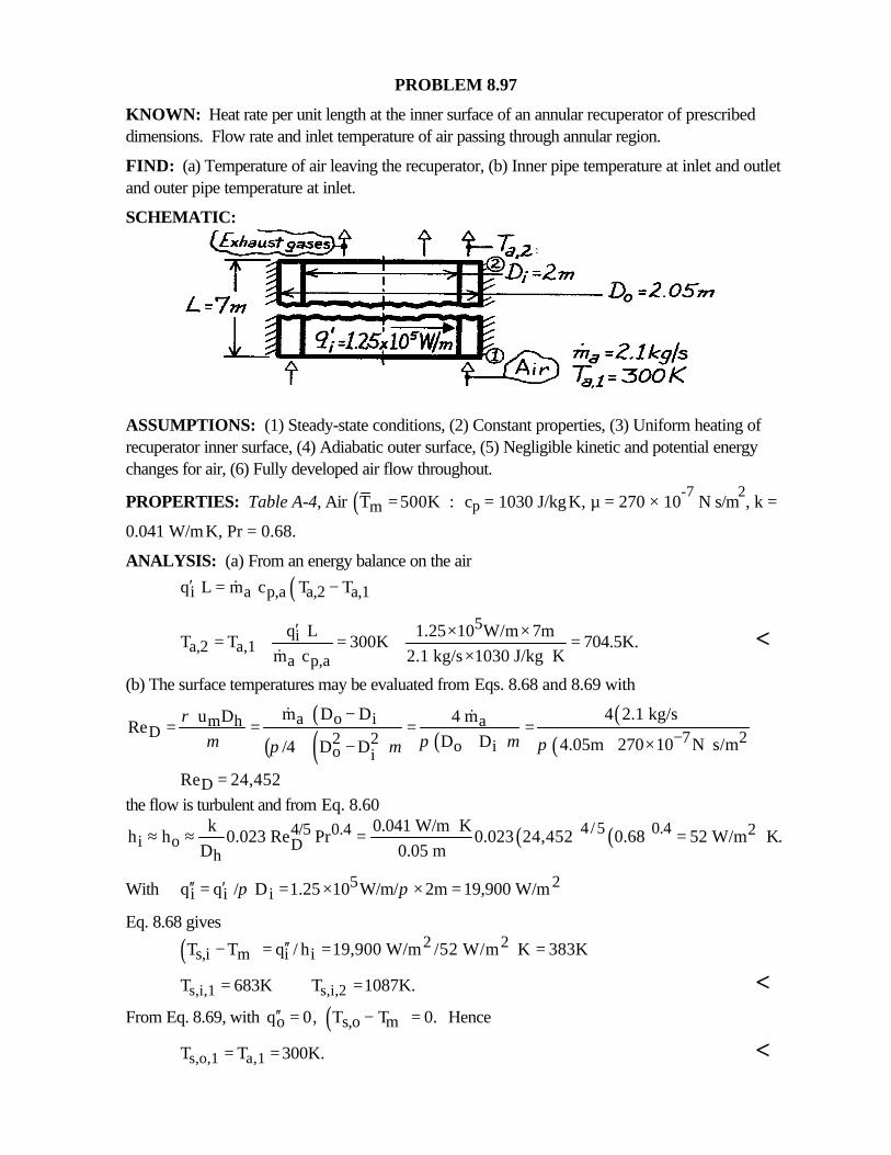
PROBLEM 8.97
KNOWN: Heat rate per unit length at the inner surface of an annular recuperator of prescribeddimensions. Flow rate and inlet temperature of air passing through annular region.
FIND: (a) Temperature of air leaving the recuperator, (b) Inner pipe temperature at inlet and outletand outer pipe temperature at inlet.
SCHEMATIC:
ASSUMPTIONS: (1) Steady-state conditions, (2) Constant properties, (3) Uniform heating ofrecuperator inner surface, (4) Adiabatic outer surface, (5) Negligible kinetic and potential energychanges for air, (6) Fully developed air flow throughout.
PROPERTIES: Table A-4, Air ( )mT 500K := cp = 1030 J/kg⋅K, µ = 270 × 10-7
N⋅s/m2, k =
0.041 W/m⋅K, Pr = 0.68.
ANALYSIS: (a) From an energy balance on the air
( )i a p,a a,2 a,1q L m c T T′ = −&
5i
a,2 a,1a p,a
q L 1.25 10 W/m 7mT T 300K 704.5K.
m c 2.1 kg/s 1030 J/kg K
′ × ×= + = + =× ⋅&
<
(b) The surface temperatures may be evaluated from Eqs. 8.68 and 8.69 with
( )( ) ( ) ( )
( )( )
a o i am hD 7 22 2 o io i
m D D 4 2.1 kg/s4 m u DRe
D D 4.05m 270 10 N s/m/4 D D
ρµ π µ ππ µ −
−= = = =
+ × ⋅−
& &
DRe 24,452=the flow is turbulent and from Eq. 8.60
( ) ( )4/5 0.44/5 0.4 2i o D
h
k 0.041 W/m Kh h 0.023 Re Pr 0.023 24,452 0.68 52 W/m K.
D 0.05 m⋅≈ ≈ = = ⋅
With 5 2i i iq q / D 1.25 10 W/m/ 2m 19,900 W/mπ π′′ ′= = × × =
Eq. 8.68 gives
( ) 2 2s,i m i iT T q / h 19,900 W/m /52 W/m K 383K′′− = = ⋅ =
s,i,1 s,i,2T 683K T 1087K.= = <From Eq. 8.69, with ( )o s,o mq 0, T T 0.′′ = − = Hence
s,o,1 a,1T T 300K.= = <
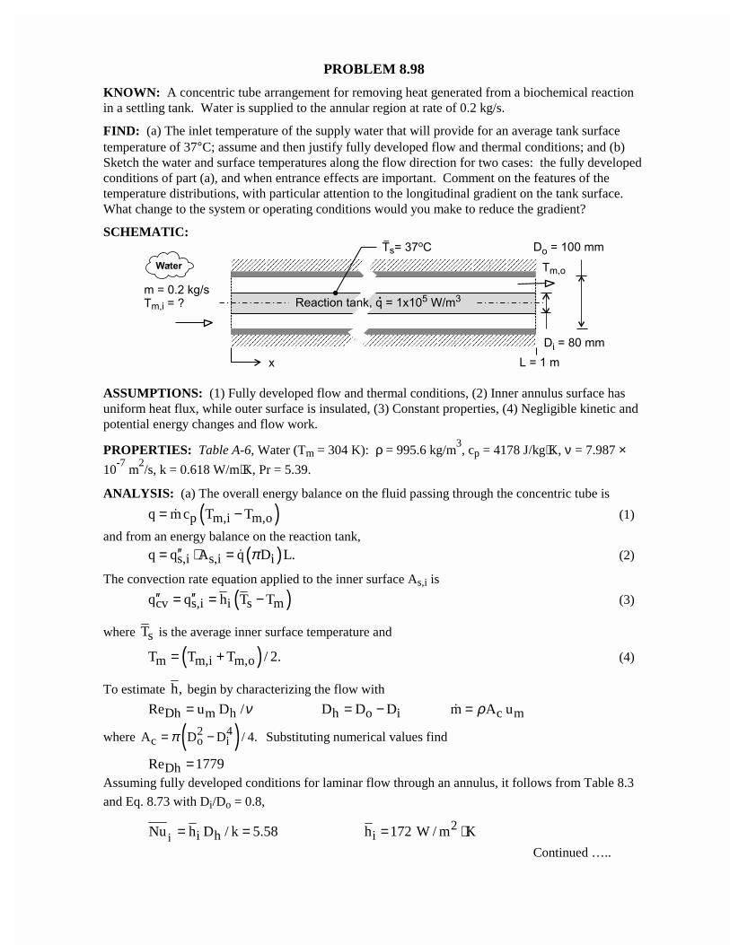
PROBLEM 8.98
KNOWN: A concentric tube arrangement for removing heat generated from a biochemical reactionin a settling tank. Water is supplied to the annular region at rate of 0.2 kg/s.
FIND: (a) The inlet temperature of the supply water that will provide for an average tank surfacetemperature of 37°C; assume and then justify fully developed flow and thermal conditions; and (b)Sketch the water and surface temperatures along the flow direction for two cases: the fully developedconditions of part (a), and when entrance effects are important. Comment on the features of thetemperature distributions, with particular attention to the longitudinal gradient on the tank surface.What change to the system or operating conditions would you make to reduce the gradient?
SCHEMATIC:
ASSUMPTIONS: (1) Fully developed flow and thermal conditions, (2) Inner annulus surface hasuniform heat flux, while outer surface is insulated, (3) Constant properties, (4) Negligible kinetic andpotential energy changes and flow work.
PROPERTIES: Table A-6, Water (Tm = 304 K): ρ = 995.6 kg/m3, cp = 4178 J/kg⋅K, ν = 7.987 ×
10-7
m2/s, k = 0.618 W/m⋅K, Pr = 5.39.
ANALYSIS: (a) The overall energy balance on the fluid passing through the concentric tube is
( )p m,i m,oq m c T T= −� (1)
and from an energy balance on the reaction tank,
( )s,i s,i iq q A q D L.π′′= ⋅ = � (2)
The convection rate equation applied to the inner surface As,i is
( )cv s,i i s mq q h T T′′ ′′= = − (3)
where sT is the average inner surface temperature and
( )m m,i m,oT T T / 2.= + (4)
To estimate h, begin by characterizing the flow with
Dh m h h o i c mRe u D / D D D m A uν ρ= = − =�
where ( )2 4c o iA D D / 4.π= − Substituting numerical values find
DhRe 1779=Assuming fully developed conditions for laminar flow through an annulus, it follows from Table 8.3
and Eq. 8.73 with Di/Do = 0.8,
i2
i h iNu h D / k 5.58 h 172 W / m K= = = ⋅Continued …..
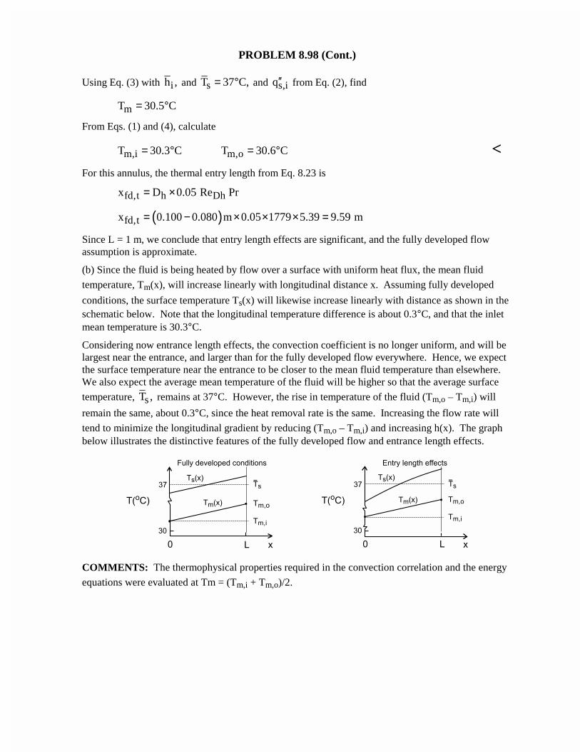
PROBLEM 8.98 (Cont.)
Using Eq. (3) with ih , and sT 37 C,= ° and s,iq′′ from Eq. (2), find
mT 30.5 C= °
From Eqs. (1) and (4), calculate
m,i m,oT 30.3 C T 30.6 C= ° = ° <For this annulus, the thermal entry length from Eq. 8.23 is
fd,t h Dhx D 0.05 Re Pr= ×
( )fd,tx 0.100 0.080 m 0.05 1779 5.39 9.59 m= − × × × =
Since L = 1 m, we conclude that entry length effects are significant, and the fully developed flowassumption is approximate.
(b) Since the fluid is being heated by flow over a surface with uniform heat flux, the mean fluid
temperature, Tm(x), will increase linearly with longitudinal distance x. Assuming fully developed
conditions, the surface temperature Ts(x) will likewise increase linearly with distance as shown in theschematic below. Note that the longitudinal temperature difference is about 0.3°C, and that the inletmean temperature is 30.3°C.
Considering now entrance length effects, the convection coefficient is no longer uniform, and will belargest near the entrance, and larger than for the fully developed flow everywhere. Hence, we expectthe surface temperature near the entrance to be closer to the mean fluid temperature than elsewhere.We also expect the average mean temperature of the fluid will be higher so that the average surface
temperature, sT , remains at 37°C. However, the rise in temperature of the fluid (Tm,o – Tm,i) will
remain the same, about 0.3°C, since the heat removal rate is the same. Increasing the flow rate will
tend to minimize the longitudinal gradient by reducing (Tm,o – Tm,i) and increasing h(x). The graphbelow illustrates the distinctive features of the fully developed flow and entrance length effects.
COMMENTS: The thermophysical properties required in the convection correlation and the energy
equations were evaluated at Tm = (Tm,i + Tm,o)/2.
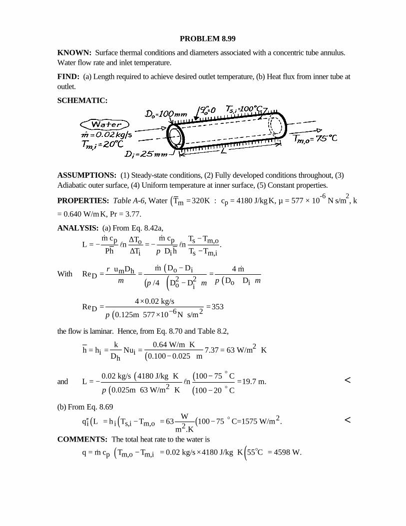
PROBLEM 8.99
KNOWN: Surface thermal conditions and diameters associated with a concentric tube annulus.Water flow rate and inlet temperature.
FIND: (a) Length required to achieve desired outlet temperature, (b) Heat flux from inner tube atoutlet.
SCHEMATIC:
ASSUMPTIONS: (1) Steady-state conditions, (2) Fully developed conditions throughout, (3)Adiabatic outer surface, (4) Uniform temperature at inner surface, (5) Constant properties.
PROPERTIES: Table A-6, Water ( )mT 320K := cp = 4180 J/kg⋅K, µ = 577 × 10-6
N⋅s/m2, k
= 0.640 W/m⋅K, Pr = 3.77.
ANALYSIS: (a) From Eq. 8.42a,
p p s m,oo
i i s m,i
m c m c T TTL n n .
Ph T D h T Tπ−∆= − = −
∆ −
& &l l
With( )
( ) ( ) ( )o im h
D 2 2 o io i
m D D u D 4 mRe
D D/4 D D
ρµ π µπ µ
−= = =
+−
& &
( )D 6 24 0.02 kg/s
Re 3530.125m 577 10 N s/mπ −
×= =
× ⋅
the flow is laminar. Hence, from Eq. 8.70 and Table 8.2,
( )2
i ih
k 0.64 W/m Kh h Nu 7.37 63 W/m K
D 0.100 0.025 m⋅
= = = = ⋅−
and( )
( )( )( )2
0.02 kg/s 4180 J/kg K 100 75 CL n 19.7 m.
0.025m 63 W/m K 100 20 Cπ
⋅ −= − =
⋅ −
o
ol <
(b) From Eq. 8.69
( ) ( ) ( ) 2i i s,i m,o 2
Wq L h T T 63 100 75 C=1575 W/m .
m .K′′ = − = − o <
COMMENTS: The total heat rate to the water is
( ) ( )p m,o m,iq m c T T 0.02 kg/s 4180 J/kg K 55 C 4598 W.= − = × ⋅ =o&
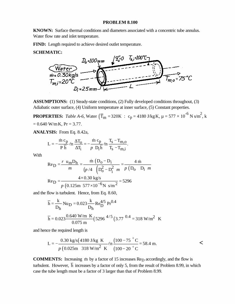
PROBLEM 8.100
KNOWN: Surface thermal conditions and diameters associated with a concentric tube annulus.Water flow rate and inlet temperature.
FIND: Length required to achieve desired outlet temperature.
SCHEMATIC:
ASSUMPTIONS: (1) Steady-state conditions, (2) Fully developed conditions throughout, (3)Adiabatic outer surface, (4) Uniform temperature at inner surface, (5) Constant properties.
PROPERTIES: Table A-6, Water ( )mT 320K := cp = 4180 J/kg⋅K, µ = 577 × 10-6
N⋅s/m2, k
= 0.640 W/m⋅K, Pr = 3.77.
ANALYSIS: From Eq. 8.42a,
p p s m,oo
i i s m,i
m c m c T TTL n n .
P h T D h T Tπ−∆= − = −
∆ −
& &l l
With( )
( ) ( ) ( )o im h
D 2 2 o io i
m D D u D 4 mRe
D D/4 D D
ρµ π µπ µ
−= = =
+−
& &
( )D 6 24 0.30 kg/s
Re 52960.125m 577 10 N s/mπ −
×= =
× ⋅and the flow is turbulent. Hence, from Eq. 8.60,
4/5 0.4D D
h h
k kh Nu 0.023 Re Pr
D D= =
( ) ( )4/5 0.4 20.640 W/m Kh 0.023 5296 3.77 318 W/m K
0.075 m⋅= = ⋅
and hence the required length is
( )( )
( )( )2
0.30 kg/s 4180 J/kg K 100 75 CL n 58.4 m.
0.025m 318 W/m K 100 20 Cπ
⋅ −= − =
⋅ −
o
ol <
COMMENTS: Increasing &m by a factor of 15 increases ReD accordingly, and the flow isturbulent. However, h increases by a factor of only 5, from the result of Problem 8.99, in whichcase the tube length must be a factor of 3 larger than that of Problem 8.99.
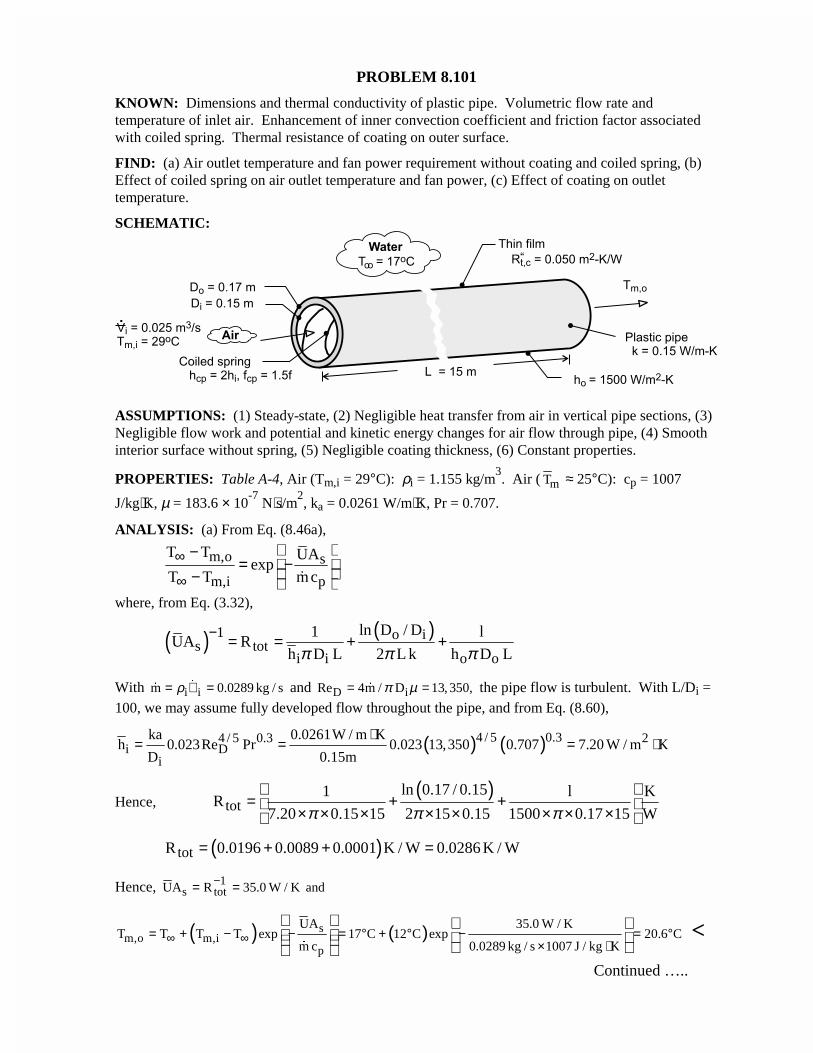
PROBLEM 8.101
KNOWN: Dimensions and thermal conductivity of plastic pipe. Volumetric flow rate andtemperature of inlet air. Enhancement of inner convection coefficient and friction factor associatedwith coiled spring. Thermal resistance of coating on outer surface.
FIND: (a) Air outlet temperature and fan power requirement without coating and coiled spring, (b)Effect of coiled spring on air outlet temperature and fan power, (c) Effect of coating on outlettemperature.
SCHEMATIC:
ASSUMPTIONS: (1) Steady-state, (2) Negligible heat transfer from air in vertical pipe sections, (3)Negligible flow work and potential and kinetic energy changes for air flow through pipe, (4) Smoothinterior surface without spring, (5) Negligible coating thickness, (6) Constant properties.
PROPERTIES: Table A-4, Air (Tm,i = 29°C): ρi = 1.155 kg/m3. Air ( mT ≈ 25°C): cp = 1007
J/kg⋅K, µ = 183.6 × 10⁻⁷
N⋅s/m2, ka = 0.0261 W/m⋅K, Pr = 0.707.
ANALYSIS: (a) From Eq. (8.46a),
m,o s
m,i p
T T UAexp
T T mc∞
∞
−= − − �
where, from Eq. (3.32),
( ) ( )1 o is tot
i i o o
ln D / D1 lUA R
h D L 2 L k h D Lπ π π− = = + +
With i im 0.0289 kg / sρ= ∀ =�
� and D iRe 4m / D 13, 350,π µ= =� the pipe flow is turbulent. With L/Di =100, we may assume fully developed flow throughout the pipe, and from Eq. (8.60),
( ) ( )4 / 5 0.34 / 5 0.3 2i D
i
ka 0.0261W / m Kh 0.023Re Pr 0.023 13,350 0.707 7.20 W / m K
D 0.15m
⋅= = = ⋅
Hence,( )
totln 0.17 / 0.151 l K
R7.20 0.15 15 2 15 0.15 1500 0.17 15 Wπ π π
= + + × × × × × × × ×
( )totR 0.0196 0.0089 0.0001 K / W 0.0286 K / W= + + =
Hence, 1s totUA R 35.0 W / K and−= =
( ) ( )sm,o m,i
p
UA 35.0 W / KT T T T exp 17 C 12 C exp 20.6 C
m c 0.0289 kg / s 1007 J / kg K∞ ∞= + − − = ° + ° − = °
× ⋅
�
<
Continued …..
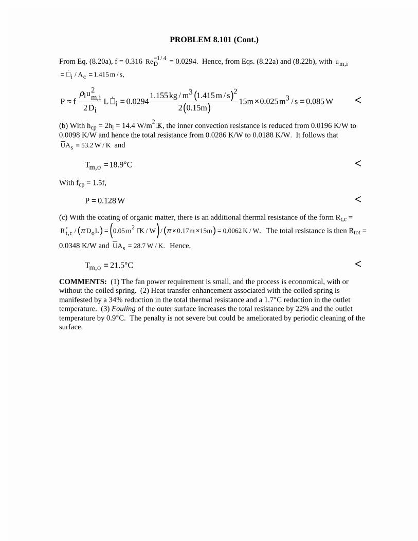
PROBLEM 8.101 (Cont.)
From Eq. (8.20a), f = 0.316 1/ 4DRe− = 0.0294. Hence, from Eqs. (8.22a) and (8.22b), with m,iu
i c/ A 1.415 m / s,= ∀ =�
( )( )
2 23i m,i 3i
i
u 1.155kg / m 1.415m / sP f L 0.0294 15m 0.025m / s 0.085 W
2D 2 0.15m
ρ≈ ∀ = × =� <
(b) With hcp = 2hi = 14.4 W/m2⋅K, the inner convection resistance is reduced from 0.0196 K/W to
0.0098 K/W and hence the total resistance from 0.0286 K/W to 0.0188 K/W. It follows that
sUA 53.2 W / K= and
m,oT 18.9 C= ° <With fcp = 1.5f,
P 0.128 W= <(c) With the coating of organic matter, there is an additional thermal resistance of the form Rt,c =
( ) ( ) ( )2t,c oR / D L 0.05 m K / W / 0.17m 15m 0.0062 K / W.π π′′ = ⋅ × × = The total resistance is then Rtot =
0.0348 K/W and sUA 28.7 W / K.= Hence,
m,oT 21.5 C= ° <COMMENTS: (1) The fan power requirement is small, and the process is economical, with orwithout the coiled spring. (2) Heat transfer enhancement associated with the coiled spring ismanifested by a 34% reduction in the total thermal resistance and a 1.7°C reduction in the outlettemperature. (3) Fouling of the outer surface increases the total resistance by 22% and the outlettemperature by 0.9°C. The penalty is not severe but could be ameliorated by periodic cleaning of thesurface.
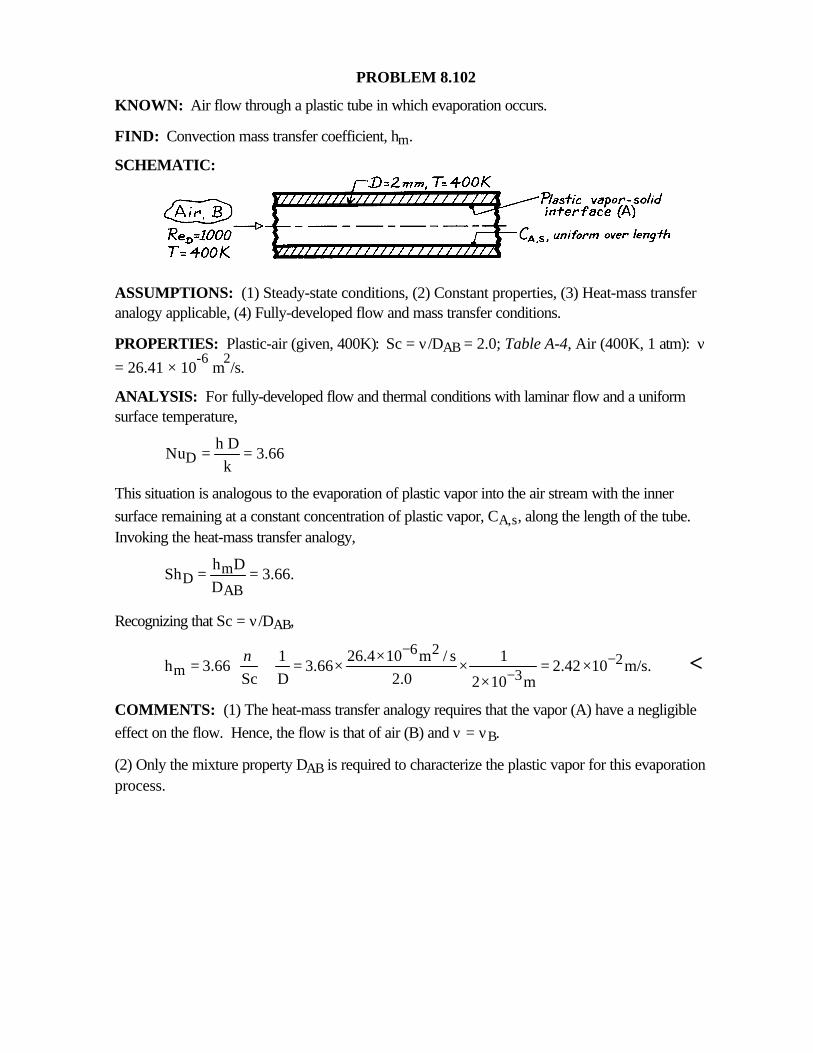
PROBLEM 8.102
KNOWN: Air flow through a plastic tube in which evaporation occurs.
FIND: Convection mass transfer coefficient, hm.
SCHEMATIC:
ASSUMPTIONS: (1) Steady-state conditions, (2) Constant properties, (3) Heat-mass transferanalogy applicable, (4) Fully-developed flow and mass transfer conditions.
PROPERTIES: Plastic-air (given, 400K): Sc = ν/DAB = 2.0; Table A-4, Air (400K, 1 atm): ν= 26.41 × 10
-6 m
2/s.
ANALYSIS: For fully-developed flow and thermal conditions with laminar flow and a uniformsurface temperature,
Dh D
Nu 3.66k
= =
This situation is analogous to the evaporation of plastic vapor into the air stream with the innersurface remaining at a constant concentration of plastic vapor, CA,s, along the length of the tube.Invoking the heat-mass transfer analogy,
mD
AB
h DSh 3.66.
D= =
Recognizing that Sc = ν/DAB,
6 22
m 31 26.4 10 m / s 1
h 3.66 3.66 2.42 10 m/s.Sc D 2.0 2 10 m
ν −−
−× = = × × = × ×
<
COMMENTS: (1) The heat-mass transfer analogy requires that the vapor (A) have a negligibleeffect on the flow. Hence, the flow is that of air (B) and ν = νB.
(2) Only the mixture property DAB is required to characterize the plastic vapor for this evaporationprocess.
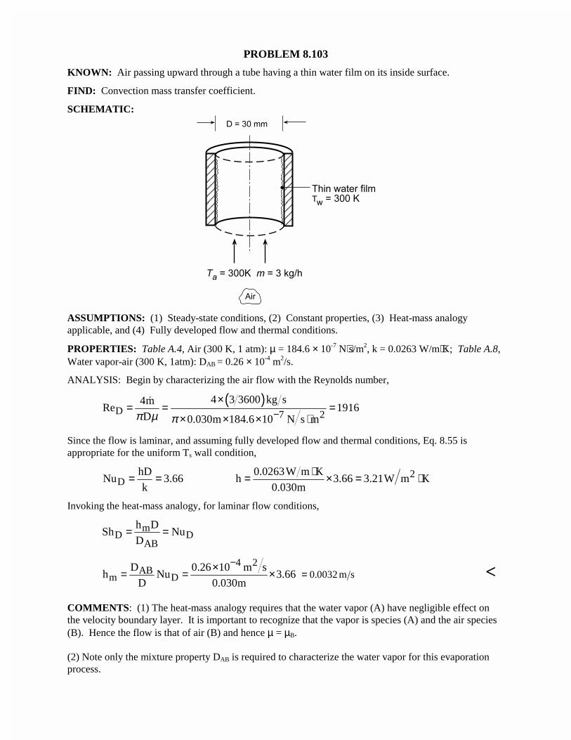
PROBLEM 8.103
KNOWN: Air passing upward through a tube having a thin water film on its inside surface.
FIND: Convection mass transfer coefficient.
SCHEMATIC:
ASSUMPTIONS: (1) Steady-state conditions, (2) Constant properties, (3) Heat-mass analogyapplicable, and (4) Fully developed flow and thermal conditions.
PROPERTIES: Table A.4, Air (300 K, 1 atm): µ = 184.6 × 10⁻⁷ N⋅s/m2, k = 0.0263 W/m⋅K; Table A.8,Water vapor-air (300 K, 1atm): DAB = 0.26 × 10⁻⁴ m2/s.
ANALYSIS: Begin by characterizing the air flow with the Reynolds number,
( )D 7 2
4 3 3600 kg s4mRe 1916
D 0.030m 184.6 10 N s mπ µ π −×
= = =× × × ⋅
�
Since the flow is laminar, and assuming fully developed flow and thermal conditions, Eq. 8.55 isappropriate for the uniform Ts wall condition,
DhD
Nu 3.66k
= = 20.0263W m Kh 3.66 3.21W m K
0.030m
⋅= × = ⋅
Invoking the heat-mass analogy, for laminar flow conditions,
mD D
AB
h DSh Nu
D= =
4 2AB
m DD 0.26 10 m s
h Nu 3.66D 0.030m
−×= = × = 0 0032. m s <
COMMENTS: (1) The heat-mass analogy requires that the water vapor (A) have negligible effect onthe velocity boundary layer. It is important to recognize that the vapor is species (A) and the air species(B). Hence the flow is that of air (B) and hence µ = µB.
(2) Note only the mixture property DAB is required to characterize the water vapor for this evaporationprocess.
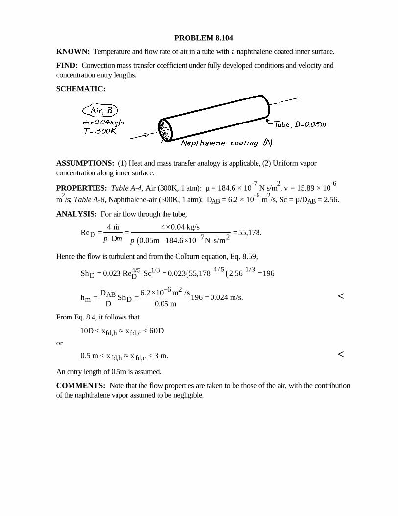
PROBLEM 8.104
KNOWN: Temperature and flow rate of air in a tube with a naphthalene coated inner surface.
FIND: Convection mass transfer coefficient under fully developed conditions and velocity andconcentration entry lengths.
SCHEMATIC:
ASSUMPTIONS: (1) Heat and mass transfer analogy is applicable, (2) Uniform vaporconcentration along inner surface.
PROPERTIES: Table A-4, Air (300K, 1 atm): µ = 184.6 × 10⁻⁷
N⋅s/m2, ν = 15.89 × 10
-6
m2/s; Table A-8, Naphthalene-air (300K, 1 atm): DAB = 6.2 × 10
-6 m
2/s, Sc = µ/DAB = 2.56.
ANALYSIS: For air flow through the tube,
( )D 7 24 m 4 0.04 kg/s
Re 55,178. D 0.05m 184.6 10 N s/mπ µ π −
×= = =
× ⋅
&
Hence the flow is turbulent and from the Colburn equation, Eq. 8.59,
( ) ( )4/5 1/34/5 1/3D DSh 0.023 Re Sc 0.023 55,178 2.56 196= = =
6 2AB
m DD 6.2 10 m /s
h Sh 196 0.024 m/s.D 0.05 m
−×= = = <
From Eq. 8.4, it follows that
fd,h fd,c10D x x 60D≤ ≈ ≤or
fd,h fd,c0.5 m x x 3 m.≤ ≈ ≤ <An entry length of 0.5m is assumed.
COMMENTS: Note that the flow properties are taken to be those of the air, with the contributionof the naphthalene vapor assumed to be negligible.
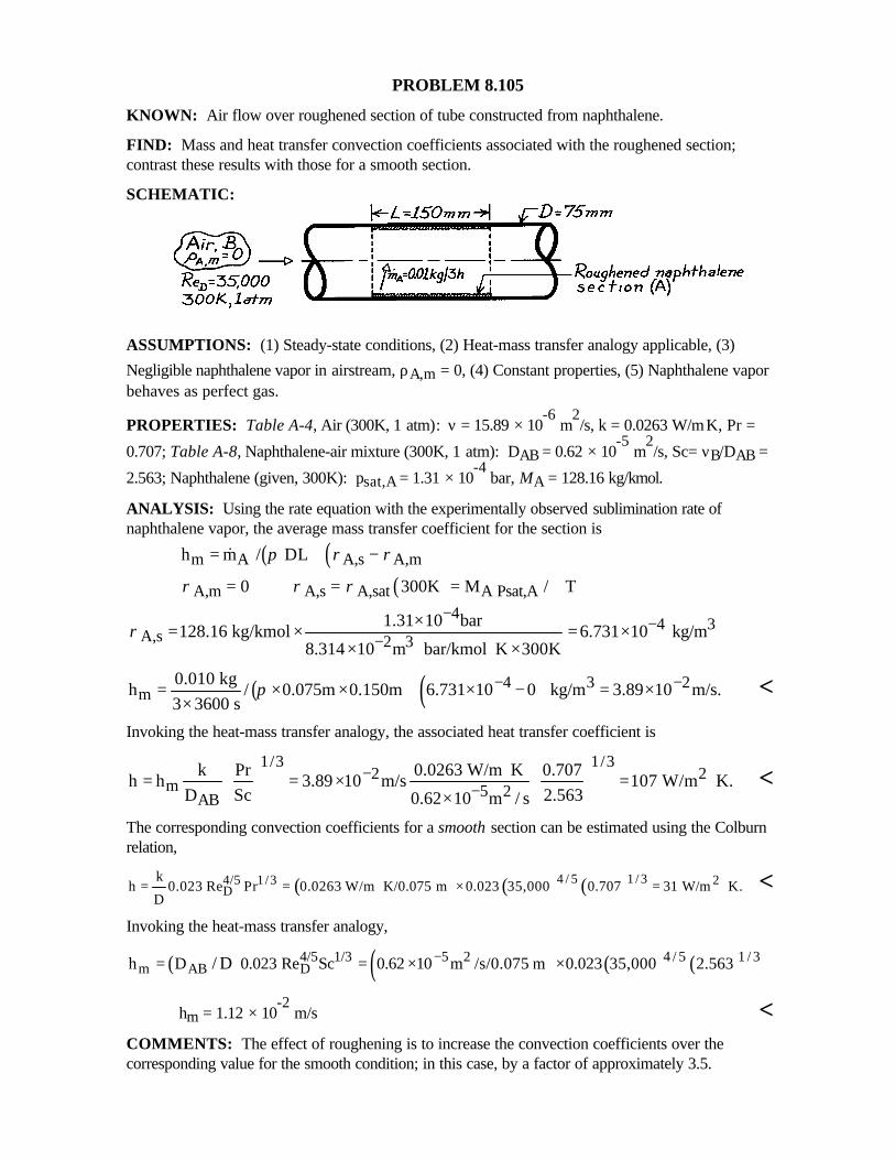
PROBLEM 8.105
KNOWN: Air flow over roughened section of tube constructed from naphthalene.
FIND: Mass and heat transfer convection coefficients associated with the roughened section;contrast these results with those for a smooth section.
SCHEMATIC:
ASSUMPTIONS: (1) Steady-state conditions, (2) Heat-mass transfer analogy applicable, (3)
Negligible naphthalene vapor in airstream, ρA,m = 0, (4) Constant properties, (5) Naphthalene vaporbehaves as perfect gas.
PROPERTIES: Table A-4, Air (300K, 1 atm): ν = 15.89 × 10⁻⁶
m2/s, k = 0.0263 W/m⋅K, Pr =
0.707; Table A-8, Naphthalene-air mixture (300K, 1 atm): DAB = 0.62 × 10⁻⁵
m2/s, Sc= νB/DAB =
2.563; Naphthalene (given, 300K): psat,A = 1.31 × 10⁻⁴
bar, MA = 128.16 kg/kmol.
ANALYSIS: Using the rate equation with the experimentally observed sublimination rate ofnaphthalene vapor, the average mass transfer coefficient for the section is
( ) ( )m A A,s A,mh m / DL π ρ ρ= −&
( )A,m A,s A,sat A Psat,A0 300K M / Tρ ρ ρ= = = ℜ4
4 3A,s 2 3
1.31 10 bar128.16 kg/kmol 6.731 10 kg/m
8.314 10 m bar/kmol K 300Kρ
−−
−×= × = ×
× ⋅ ⋅ ×
( ) ( )4 3 2m
0.010 kgh / 0.075m 0.150m 6.731 10 0 kg/m 3.89 10 m/s.
3 3600 sπ − −= × × × − = ×
×<
Invoking the heat-mass transfer analogy, the associated heat transfer coefficient is
1/3 1/32 2
m 5 2AB
k Pr 0.0263 W/m K 0.707h h 3.89 10 m/s 107 W/m K.
D Sc 2.5630.62 10 m / s−
−⋅ = = × = ⋅ ×
<
The corresponding convection coefficients for a smooth section can be estimated using the Colburnrelation,
( ) ( ) ( )4 / 5 1 / 34/5 1/3 2D
kh 0.023 Re Pr 0.0263 W/m K/0.075 m 0.023 35,000 0.707 31 W/m K.
D= = ⋅ × = ⋅ <
Invoking the heat-mass transfer analogy,
( ) ( ) ( ) ( )4 / 5 1 / 34/5 1/3 5 2m AB Dh D 0.023 Re Sc 0.62 10 m /s/0.075 m 0.023 35,000 2.563/ D −= = × ×
hm = 1.12 × 10⁻²
m/s <COMMENTS: The effect of roughening is to increase the convection coefficients over thecorresponding value for the smooth condition; in this case, by a factor of approximately 3.5.
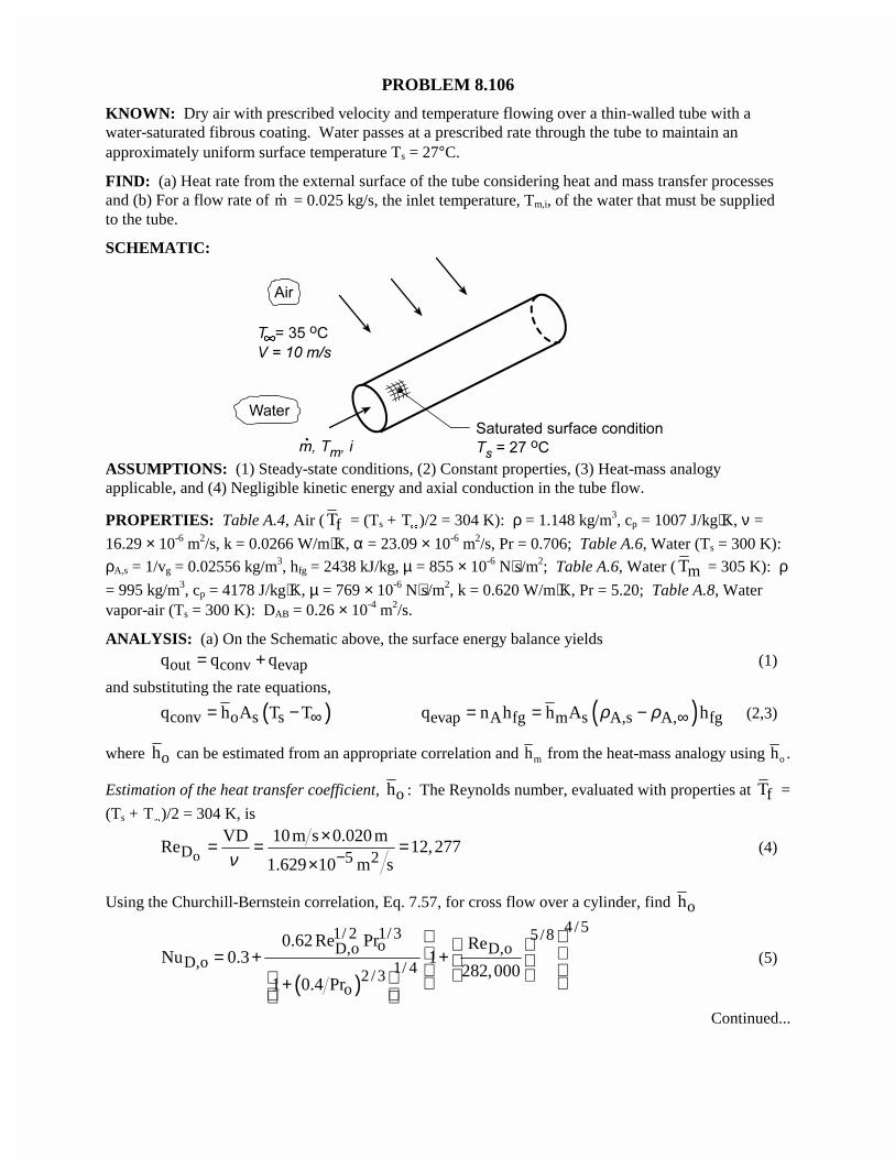
PROBLEM 8.106
KNOWN: Dry air with prescribed velocity and temperature flowing over a thin-walled tube with awater-saturated fibrous coating. Water passes at a prescribed rate through the tube to maintain anapproximately uniform surface temperature Ts = 27°C.
FIND: (a) Heat rate from the external surface of the tube considering heat and mass transfer processesand (b) For a flow rate of �m = 0.025 kg/s, the inlet temperature, Tm,i, of the water that must be suppliedto the tube.
SCHEMATIC:
ASSUMPTIONS: (1) Steady-state conditions, (2) Constant properties, (3) Heat-mass analogyapplicable, and (4) Negligible kinetic energy and axial conduction in the tube flow.
PROPERTIES: Table A.4, Air ( fT = (Ts + T�
)/2 = 304 K): ρ = 1.148 kg/m3, cp = 1007 J/kg⋅K, ν =
16.29 × 10⁻⁶ m2/s, k = 0.0266 W/m⋅K, α = 23.09 × 10⁻⁶ m2/s, Pr = 0.706; Table A.6, Water (Ts = 300 K):
ρA,s = 1/vg = 0.02556 kg/m3, hfg = 2438 kJ/kg, µ = 855 × 10-6 N⋅s/m2; Table A.6, Water ( mT = 305 K): ρ= 995 kg/m3, cp = 4178 J/kg⋅K, µ = 769 × 10-6 N⋅s/m2, k = 0.620 W/m⋅K, Pr = 5.20; Table A.8, Watervapor-air (Ts = 300 K): DAB = 0.26 × 10⁻⁴ m2/s.
ANALYSIS: (a) On the Schematic above, the surface energy balance yields
out conv evapq q q= + (1)
and substituting the rate equations,
( )conv o s sq h A T T∞= − ( )evap A fg m s A,s A, fgq n h h A hρ ρ ∞= = − (2,3)
where oh can be estimated from an appropriate correlation and hm from the heat-mass analogy using ho .
Estimation of the heat transfer coefficient, oh : The Reynolds number, evaluated with properties at fT =
(Ts + T�
)/2 = 304 K, is
oD 5 2VD 10m s 0.020 m
Re 12,2771.629 10 m sν −
×= = =×
(4)
Using the Churchill-Bernstein correlation, Eq. 7.57, for cross flow over a cylinder, find oh
( )
4 /51/ 2 1/3 5/8oD,o D,o
D,o 1/ 42 /3o
0.62 Re Pr ReNu 0.3 1
282,0001 0.4 Pr
= + + +
(5)
Continued...
PROBLEM 8.106 (Cont.)
( ) ( )
( )
4 /51/ 2 1/ 3 5/8
D,o 1/ 42 /3
0.62 12, 277 0.706 12, 277Nu 0.3 1
282,0001 0.4 0.706
= + + +
2o D,o
k 0.0266 W m Kh Nu 60.1 80.0 W m K
D 0.020m
⋅= = × = ⋅
The Heat-Mass Analogy: From Eq. 6.92, with n = 1/3,2 /3
2 /3op p
m AB
hc Le c
h D
αρ ρ
= =
(6)
( )2 / 32 3 6 2 4 2mh 80.0 W m K 1.148 kg m 1007 J kg K 23.09 10 m s 0.26 10 m s 0.0749 m s− −= ⋅ × ⋅ × × =
Hence, the heat rate leaving the tube surface from Eq. (1) is,
( ) ( ) ( )2 3 3outq 80 W m K 27 35 C 0.0749 m s 0.02556 0 kg m 2438 10 J kg 0.020 m 0.200 mπ= ⋅ − + − × × × ×
$
outq 8.04 W 58.65 50.6 W= − + = <(b) For tube flow analysis, the heat rate and rate equations are
( )p m,o m,iq mc T T= −� s m,o
is m,i p
T T DLexp h
T T mc
π −= − − �
(7,8)
where Ts = 27°C, the uniform temperature of the tube surface, and q = -50.6 W according to the analysis
of part (a). To estimate ih , first characterize the flow,
D,i 6 2i
4m 4 0.025kg sRe 2070
D 0.020 m 769 10 N s mπ µ π −×= = =
× × × ⋅
�(9)
using properties evaluated at an assumed mean temperature, mT = 305 K (slightly above Ts). The flowis laminar, and assuming a combined entry region, use the Sieder-Tate correlation, Eq. 8.57,
1/3 0.14D,i i
D,is
Re PrNu 1.86
L D
µµ
=
(10)
0.141/3 6D,i 6
2070 5.20 769 10Nu 1.86
0.200 0.020 855 10
−
−
× × = ×
2iD,ii
k 0.620 W m Kh Nu 18.78 582 W m K
D 0.020 m⋅= = × = ⋅
Referring to Eqs. (7) and (8), recognize that there are two unknowns, Tm,i and Tm,o, as we have evaluatedboth q and hi . Using the IHT solver, we found
T Cm i, . 34 2$ T Cm o, . 33 7$ <
Continued...
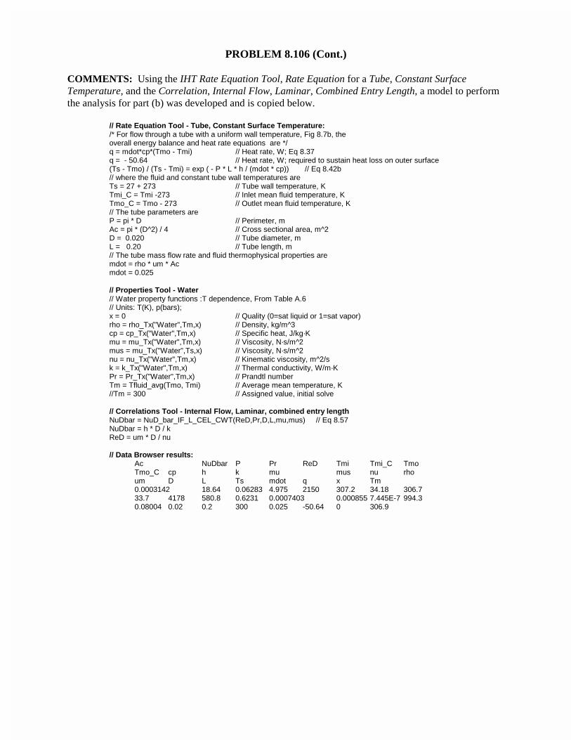
PROBLEM 8.106 (Cont.)
COMMENTS: Using the IHT Rate Equation Tool, Rate Equation for a Tube, Constant SurfaceTemperature, and the Correlation, Internal Flow, Laminar, Combined Entry Length, a model to performthe analysis for part (b) was developed and is copied below.
// Rate Equation Tool - Tube, Constant Surface Temperature:/* For flow through a tube with a uniform wall temperature, Fig 8.7b, theoverall energy balance and heat rate equations are */q = mdot*cp*(Tmo - Tmi) // Heat rate, W; Eq 8.37q = - 50.64 // Heat rate, W; required to sustain heat loss on outer surface(Ts - Tmo) / (Ts - Tmi) = exp ( - P * L * h / (mdot * cp)) // Eq 8.42b// where the fluid and constant tube wall temperatures areTs = 27 + 273 // Tube wall temperature, KTmi_C = Tmi -273 // Inlet mean fluid temperature, KTmo_C = Tmo - 273 // Outlet mean fluid temperature, K// The tube parameters areP = pi * D // Perimeter, mAc = pi * (D^2) / 4 // Cross sectional area, m^2D = 0.020 // Tube diameter, mL = 0.20 // Tube length, m// The tube mass flow rate and fluid thermophysical properties aremdot = rho * um * Acmdot = 0.025
// Properties Tool - Water// Water property functions :T dependence, From Table A.6// Units: T(K), p(bars);x = 0 // Quality (0=sat liquid or 1=sat vapor)rho = rho_Tx("Water",Tm,x) // Density, kg/m^3cp = cp_Tx("Water",Tm,x) // Specific heat, J/kg·Kmu = mu_Tx("Water",Tm,x) // Viscosity, N·s/m^2mus = mu_Tx("Water",Ts,x) // Viscosity, N·s/m^2nu = nu_Tx("Water",Tm,x) // Kinematic viscosity, m^2/sk = k_Tx("Water",Tm,x) // Thermal conductivity, W/m·KPr = Pr_Tx("Water",Tm,x) // Prandtl numberTm = Tfluid_avg(Tmo, Tmi) // Average mean temperature, K//Tm = 300 // Assigned value, initial solve
// Correlations Tool - Internal Flow, Laminar, combined entry lengthNuDbar = NuD_bar_IF_L_CEL_CWT(ReD,Pr,D,L,mu,mus) // Eq 8.57NuDbar = h * D / kReD = um * D / nu
// Data Browser results:Ac NuDbar P Pr ReD Tmi Tmi_C TmoTmo_C cp h k mu mus nu rhoum D L Ts mdot q x Tm0.0003142 18.64 0.06283 4.975 2150 307.2 34.18 306.733.7 4178 580.8 0.6231 0.0007403 0.000855 7.445E-7 994.30.08004 0.02 0.2 300 0.025 -50.64 0 306.9
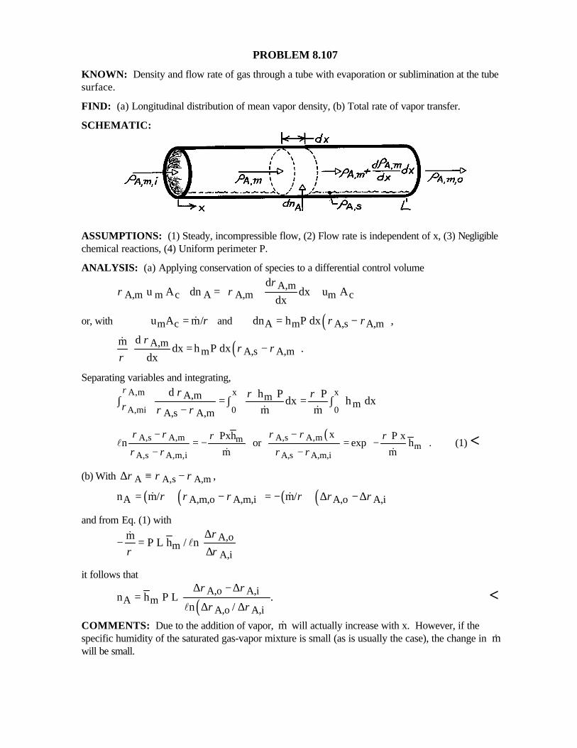
PROBLEM 8.107
KNOWN: Density and flow rate of gas through a tube with evaporation or sublimination at the tubesurface.
FIND: (a) Longitudinal distribution of mean vapor density, (b) Total rate of vapor transfer.
SCHEMATIC:
ASSUMPTIONS: (1) Steady, incompressible flow, (2) Flow rate is independent of x, (3) Negligiblechemical reactions, (4) Uniform perimeter P.
ANALYSIS: (a) Applying conservation of species to a differential control volume
A,mA,m m c A A,m m c
d u A dn dx u A
dx
ρρ ρ
+ = +
or, with m cu A m/ρ= & and ( )A m A,s A,mdn h P dx ,ρ ρ= −
( )A,mm A,s A,m
d m dx h P dx .
dx
ρρ ρ
ρ= −
&
Separating variables and integrating,x xA,m
A,mi 0 0
A,m mm
A,s A,m
d h P P dx h dx
m m
ρ
ρρ ρ ρ
ρ ρ∫ = ∫ = ∫
− & &
( )A,s A,m A,s A,mmm
A,s A,m,i A,s A,m,i
x Pxh P xn or exp h .
m m
ρ ρ ρ ρρ ρρ ρ ρ ρ
− −= − = −
− −
l& &
(1) <
(b) With A A,s A,m ,ρ ρ ρ∆ ≡ −
( ) ( ) ( ) ( )A A,m,o A,m,i A,o A,in m/ m/ ρ ρ ρ ρ ρ ρ= − = − ∆ − ∆& &
and from Eq. (1) with
A,om
A,i
mP L h / n
ρρ ρ
∆− =
∆&
l
it follows that
( )A,o A,i
A mA,o A,i
n h P L .n /
ρ ρ
ρ ρ
∆ − ∆=
∆ ∆l<
COMMENTS: Due to the addition of vapor, m& will actually increase with x. However, if thespecific humidity of the saturated gas-vapor mixture is small (as is usually the case), the change in &mwill be small.
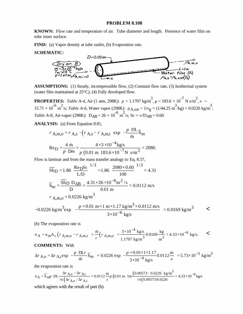
PROBLEM 8.108
KNOWN: Flow rate and temperature of air. Tube diameter and length. Presence of water film ontube inner surface.
FIND: (a) Vapor density at tube outlet, (b) Evaporation rate.
SCHEMATIC:
ASSUMPTIONS: (1) Steady, incompressible flow, (2) Constant flow rate, (3) Isothermal system(water film maintained at 25°C), (4) Fully developed flow.
PROPERTIES: Table A-4, Air (1 atm, 298K): ρ = 1.1707 kg/m3, µ = 183.6 × 10
-7 N⋅s/m
2, ν =
15.71 × 10⁻⁶
m2/s; Table A-6, Water vapor (298K): ρA,sat = 1/vg = (1/44.25 m
3/kg) = 0.0226 kg/m
3;
Table A-8, Air-vapor (298K): DAB = 26 × 10-6
m2/s; Sc = ν/DAB = 0.60.
ANALYSIS: (a) From Equation 8.81,
( )A,m,o A,s A,s A,m,i m DL
exp hm
πρ ρ ρ ρ = − − − &
( )
4D 7 2
4 m 4 3 10 kg/sRe 2080.
D 0.01 m 183.6 10 N s/mπ µ π
−
−× ×= = =
× ⋅
&
Flow is laminar and from the mass transfer analogy to Eq. 8.57,1/3 1/3
DD
Re Sc 2080 0.60Sh 1.86 1.86 4.31
L/D 100× = = =
6 2D AB
mSh D 4.31 26 10 m /s
h 0.0112 m/sD 0.01 m
−× ×= = =
3A,m,o 0.0226 kg/mρ =
33 3
40.01 m 1 m 1.17 kg/m 0.0112 m/s
0.0226 kg/m exp 0.0169 kg/m3 10 kg/s
π−
× × × × − − = × <
(b) The evaporation rate is
( ) ( )4
6A m c A,m,o A,m,i A,m,o 3 3
m 3 10 kg/s kgn u A 0.0169 4.33 10 kg/s.
1.1707 kg/m mρ ρ ρ
ρ
−−×
= − = = = ×& <
COMMENTS: With
3 3A,o A,i m 4
DL 0.01 1 1.17 mexp h 0.0226 exp 0.0112 5.73 10 kg/m
m s3 10 kg/s
π ρ πρ ρ −
−
× × × ∆ = ∆ − = − = × × &
the evaporation rate is
( ) ( ) ( )( )
3A,o A,i 6
A mA,o A,i
0.00573 0.0226 kg/mmn h DL 0.0112 0.01 m 1m 4.33 10 kg/s
s n 0.00573/0.0226n /
ρ ρπ π
ρ ρ−∆ − ∆ −
= = = ×∆ ∆ ll
which agrees with the result of part (b).
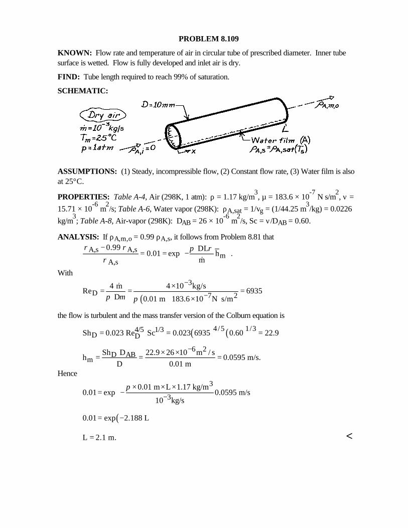
PROBLEM 8.109
KNOWN: Flow rate and temperature of air in circular tube of prescribed diameter. Inner tubesurface is wetted. Flow is fully developed and inlet air is dry.
FIND: Tube length required to reach 99% of saturation.
SCHEMATIC:
ASSUMPTIONS: (1) Steady, incompressible flow, (2) Constant flow rate, (3) Water film is alsoat 25°C.
PROPERTIES: Table A-4, Air (298K, 1 atm): ρ = 1.17 kg/m3, µ = 183.6 × 10
-7 N⋅s/m2
, ν =
15.71 × 10⁻⁶
m2/s; Table A-6, Water vapor (298K): ρA,sat = 1/vg = (1/44.25 m
3/kg) = 0.0226
kg/m3; Table A-8, Air-vapor (298K): DAB = 26 × 10
-6 m
2/s, Sc = ν/DAB = 0.60.
ANALYSIS: If ρA,m,o = 0.99 ρA,s, it follows from Problem 8.81 that
A,s A,sm
A,s
0.99 DL0.01 exp h .
m
ρ ρ π ρρ
− = = − &
With
( )
3D 7 2
4 m 4 10 kg/sRe 6935
D 0.01 m 183.6 10 N s/mπ µ π
−
−×= = =
× ⋅
&
the flow is turbulent and the mass transfer version of the Colburn equation is
( ) ( )4/5 1/34/5 1/3D DSh 0.023 Re Sc 0.023 6935 0.60 22.9= = =
6 2D AB
mSh D 22.9 26 10 m / s
h 0.0595 m/s.D 0.01 m
−× ×= = =
Hence3
30.01 m L 1.17 kg/m
0.01 exp 0.0595 m/s10 kg/s
π−
× × × = −
( )0.01 exp 2.188 L= −
L 2.1 m.= <
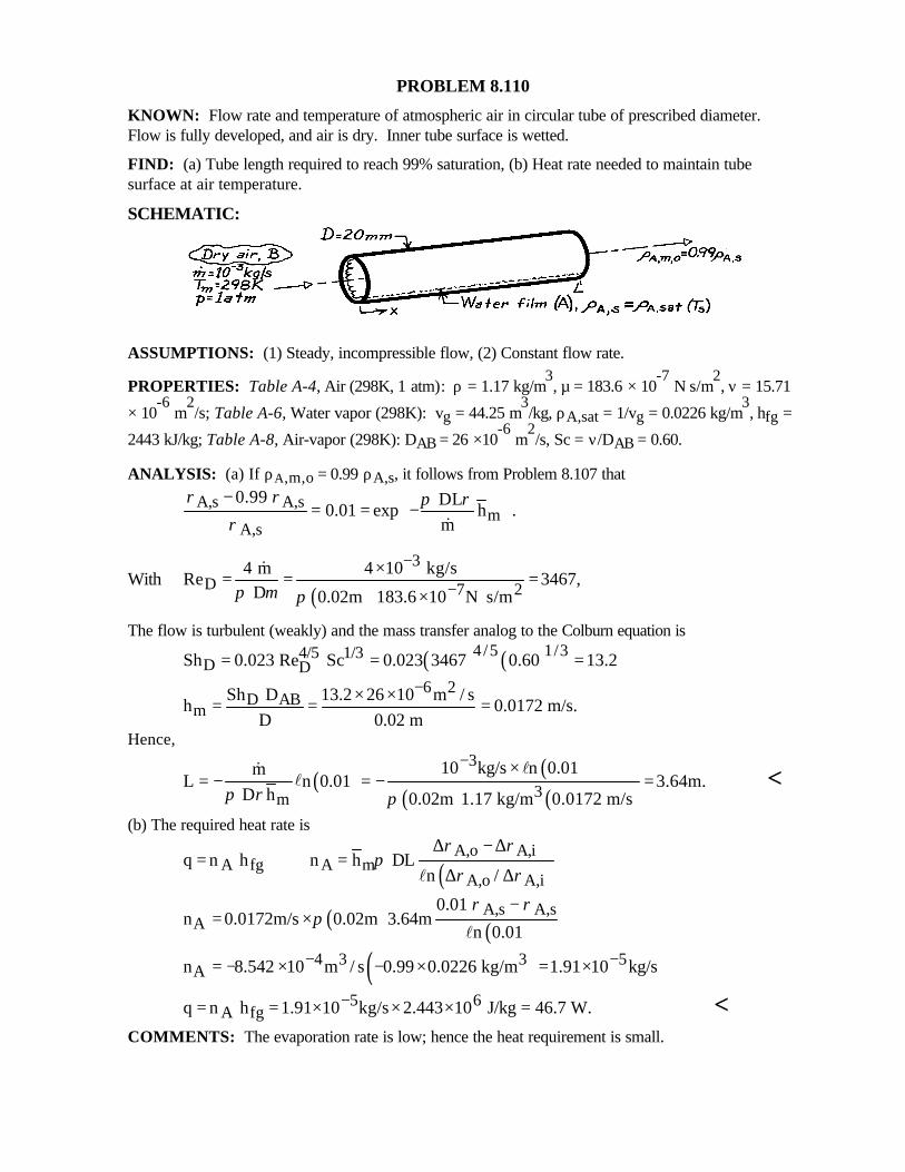
PROBLEM 8.110
KNOWN: Flow rate and temperature of atmospheric air in circular tube of prescribed diameter.Flow is fully developed, and air is dry. Inner tube surface is wetted.
FIND: (a) Tube length required to reach 99% saturation, (b) Heat rate needed to maintain tubesurface at air temperature.
SCHEMATIC:
ASSUMPTIONS: (1) Steady, incompressible flow, (2) Constant flow rate.
PROPERTIES: Table A-4, Air (298K, 1 atm): ρ = 1.17 kg/m3, µ = 183.6 × 10
-7 N⋅s/m
2, ν = 15.71
× 10-6
m2/s; Table A-6, Water vapor (298K): vg = 44.25 m
3/kg, ρA,sat = 1/vg = 0.0226 kg/m
3, hfg =
2443 kJ/kg; Table A-8, Air-vapor (298K): DAB = 26 ×10-6
m2/s, Sc = ν/DAB = 0.60.
ANALYSIS: (a) If ρA,m,o = 0.99 ρA,s, it follows from Problem 8.107 that
A,s A,sm
A,s
0.99 DL0.01 exp h .
m
ρ ρ π ρρ
− = = − &
With( )
3D 7 2
4 m 4 10 kg/sRe 3467,
D 0.02m 183.6 10 N s/mπ µ π
−
−×= = =
× ⋅
&
The flow is turbulent (weakly) and the mass transfer analog to the Colburn equation is
( ) ( )4/5 1/34/5 1/3D DSh 0.023 Re Sc 0.023 3467 0.60 13.2= = =
6 2D AB
mSh D 13.2 26 10 m / s
h 0.0172 m/s.D 0.02 m
−× ×= = =
Hence,
( ) ( )( ) ( )
3
3m
10 kg/s n 0.01mL n 0.01 3.64m.
D h 0.02m 1.17 kg/m 0.0172 m/sπ ρ π
− ×= − = − =
l&l <
(b) The required heat rate is
( )A,o A,i
A fg A mA,o A,i
q n h n h DLn /
ρ ρπ
ρ ρ
∆ − ∆= =
∆ ∆l
( ) ( )A,s A,s
A0.01
n 0.0172m/s 0.02m 3.64mn 0.01
ρ ρπ
−= ×
l
( )4 3 3 5An 8.542 10 m / s 0.99 0.0226 kg/m 1.91 10 kg/s− −= − × − × = ×
5 6A fgq n h 1.91 10 kg/s 2.443 10 J/kg 46.7 W.−= = × × × = <
COMMENTS: The evaporation rate is low; hence the heat requirement is small.
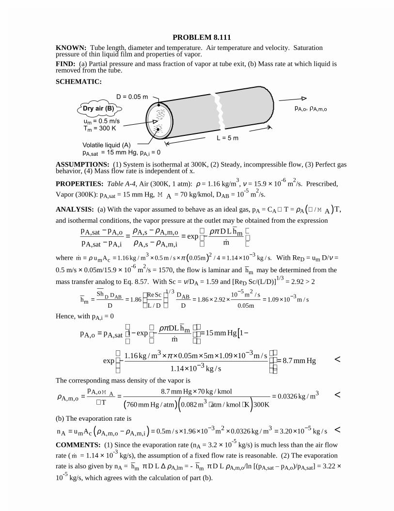
PROBLEM 8.111KNOWN: Tube length, diameter and temperature. Air temperature and velocity. Saturationpressure of thin liquid film and properties of vapor.FIND: (a) Partial pressure and mass fraction of vapor at tube exit, (b) Mass rate at which liquid isremoved from the tube.
SCHEMATIC:
ASSUMPTIONS: (1) System is isothermal at 300K, (2) Steady, incompressible flow, (3) Perfect gasbehavior, (4) Mass flow rate is independent of x.
PROPERTIES: Table A-4, Air (300K, 1 atm): ρ = 1.16 kg/m3, ν = 15.9 × 10
-6 m
2/s. Prescribed,
Vapor (300K): pA,sat = 15 mm Hg, AM = 70 kg/kmol, DAB = 10-5
m2/s.
ANALYSIS: (a) With the vapor assumed to behave as an ideal gas, pA = CA ℜ T = ρA( )/ A T,ℜ M
and isothermal conditions, the vapor pressure at the outlet may be obtained from the expression
A,sat A,o A,s A,m,o m
A,sat A,i A,s A,m,i
p p D L hexp
p p m
ρ ρ ρπρ ρ
− − = = − − − �
where ( )3 32m cm u A 1.16 kg / m 0.5 m / s 0.05m / 4 1.14 10 kg / s.ρ π −= = × × = ×� With ReD = um D/ν =
0.5 m/s × 0.05m/15.9 × 10-6
m2/s = 1570, the flow is laminar and mh may be determined from the
mass transfer analog to Eq. 8.57. With Sc = ν/DA = 1.59 and [ReD Sc/(L/D)]1/3
= 2.92 > 2
D AB5 21/ 3
D 3ABm
Sh ReSc D 10 m / sh 1.86 1.86 2.92 1.09 10 m / s
D L / D D 0.05m
−−= = = × × = ×
Hence, with pA,i = 0
[mA,o A,sat
DL hp p l exp 15mm Hg 1
m
ρπ = − − = −
�
3 3
31.16kg / m 0.05m 5m 1.09 10 m / s
exp 8.7 mm Hg1.14 10 kg / s
π −
−
× × × × × − = × <
The corresponding mass density of the vapor is
( )( )AA,o 3
A,m,o 3
p 8.7 mm Hg 70 kg / kmol0.0326 kg / m
T 760 mm Hg / atm 0.082 m atm / kmol K 300Kρ
×= = =
ℜ ⋅ ⋅
M <
(b) The evaporation rate is
( ) 3 2 3 5A m c A,m,o A,m,in u A 0.5m / s 1.96 10 m 0.0326 kg / m 3.20 10 kg / sρ ρ − −= − = × × × = × <
COMMENTS: (1) Since the evaporation rate (nA = 3.2 × 10⁻⁵
kg/s) is much less than the air flow
rate ( m� = 1.14 × 10⁻³
kg/s), the assumption of a fixed flow rate is reasonable. (2) The evaporation
rate is also given by nA = mh π D L ∆ ρA,lm = - mh π D L ρA,m,o/ln [(pA,sat – pA,o)/pA,sat] = 3.22 ×
10-5
kg/s, which agrees with the calculation of part (b).
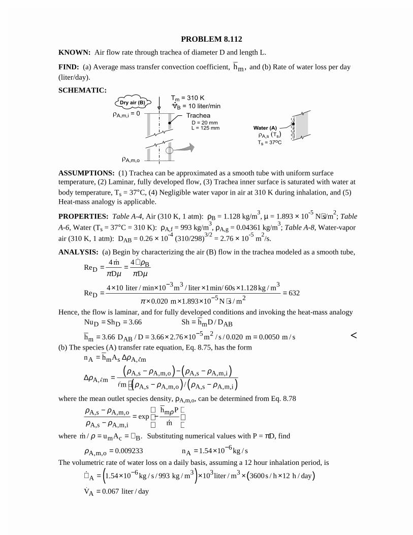
PROBLEM 8.112
KNOWN: Air flow rate through trachea of diameter D and length L.
FIND: (a) Average mass transfer convection coefficient, mh , and (b) Rate of water loss per day(liter/day).
SCHEMATIC:
ASSUMPTIONS: (1) Trachea can be approximated as a smooth tube with uniform surfacetemperature, (2) Laminar, fully developed flow, (3) Trachea inner surface is saturated with water at
body temperature, Ts = 37°C, (4) Negligible water vapor in air at 310 K during inhalation, and (5)Heat-mass analogy is applicable.
PROPERTIES: Table A-4, Air (310 K, 1 atm): ρB = 1.128 kg/m3, µ = 1.893 × 10
-5 N⋅s/m
2; Table
A-6, Water (Ts = 37°C = 310 K): ρA,f = 993 kg/m3, ρA,g = 0.04361 kg/m
3; Table A-8, Water-vapor
air (310 K, 1 atm): DAB = 0.26 × 10⁻⁴
(310/298)3/2
= 2.76 × 10⁻⁵
m2/s.
ANALYSIS: (a) Begin by characterizing the air (B) flow in the trachea modeled as a smooth tube,
BD
4 m 4Re
D D
ρπ µ π µ
∀= =
��
3 3 3
D 5 2
4 10 liter / min 10 m / liter 1min/ 60s 1.128 kg / mRe 632
0.020 m 1.893 10 N s / mπ
−
−× × × ×
= =× × × ⋅
Hence, the flow is laminar, and for fully developed conditions and invoking the heat-mass analogy
D D m ABNu Sh 3.66 Sh h D / D= = =5 2
m ABh 3.66 D / D 3.66 2.76 10 m / s / 0.020 m 0.0050 m / s−= = × × = <(b) The species (A) transfer rate equation, Eq. 8.75, has the form
A m s A, mn h A ρ= ∆ "
( ) ( )( ) ( )A,s A,m,o A,s A,m,i
A, mA,s A,m,o A,s A,m,im /
ρ ρ ρ ρρ
ρ ρ ρ ρ
− − −∆ =
− −"
"
where the mean outlet species density, ρA,m,o, can be determined from Eq. 8.78
mA,s A,m,o
A,s A,m,i
h Pexp
m
ρρ ρ
ρ ρ
−= −
−
�
where m c Bm / u A .ρ = = ∀� Substituting numerical values with P = πD, find
6A,m,o A0.009233 n 1.54 10 kg / sρ −= = ×
The volumetric rate of water loss on a daily basis, assuming a 12 hour inhalation period, is
( ) ( )6 3 3 3A 1.54 10 kg / s / 993 kg / m 10 liter / m 3600s / h 12 h / day−∀ = × × × ×�
AV 0.067 liter / day=�
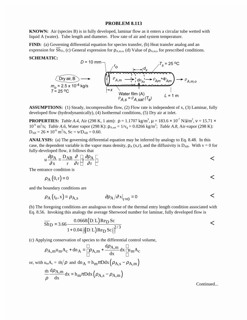
PROBLEM 8.113
KNOWN: Air (species B) is in fully developed, laminar flow as it enters a circular tube wetted withliquid A (water). Tube length and diameter. Flow rate of air and system temperature.
FIND: (a) Governing differential equation for species transfer, (b) Heat transfer analog and anexpression for ShD, (c) General expression for ρA,m,o, (d) Value of ρA,m,o for prescribed conditions.
SCHEMATIC:
ASSUMPTIONS: (1) Steady, incompressible flow, (2) Flow rate is independent of x, (3) Laminar, fullydeveloped flow (hydrodynamically), (4) Isothermal conditions, (5) Dry air at inlet.
PROPERTIES: Table A.4, Air (298 K, 1 atm): ρ = 1.1707 kg/m3, µ = 183.6 × 10⁻⁷ N⋅s/m2, ν = 15.71 ×10⁻⁶ m2/s; Table A.6, Water vapor (298 K): ρA,sat = 1/vg = 0.0266 kg/m3; Table A.8, Air-vapor (298 K):DAB = 26 × 10-6 m2/s, Sc = ν/DAB = 0.60.
ANALYSIS: (a) The governing differential equation may be inferred by analogy to Eq. 8.48. In thiscase, the dependent variable is the vapor mass density, ρA (x,r), and the diffusivity is DAB. With v = 0 forfully-developed flow, it follows that
A AB ADu r
x r r r
∂ρ ∂ ∂ρ∂ ∂ ∂
= <
The entrance condition is
( )A 0, r 0ρ = <and the boundary conditions are
( )A o A,sr , xρ ρ= A r 0x 0∂ρ ∂ = = <(b) The foregoing conditions are analogous to those of the thermal entry length condition associated withEq. 8.56. Invoking this analogy the average Sherwood number for laminar, fully developed flow is
( )( )
DD 2/3
D
0.0668 D L Re ScSh 3.66
1 0.04 D L Re Sc=
+ <
(c) Applying conservation of species to the differential control volume,
A,mA,m m c A A,m m c
du A dn dx u A
dx
ρρ ρ
+ = +
or, with umAc = m ρ� and ( )A m A,s A,mdn h Ddxπ ρ ρ= −
( )A,mm A,s A,m
dmdx h Ddx
dx
ρπ ρ ρ
ρ= −
�
Continued...
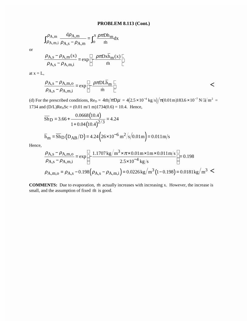
PROBLEM 8.113 (Cont.)
A,m
A,m,i
xA,m moA,s A,m
d Dhdx
m
ρρ
ρ ρπρ ρ
=−∫ ∫
�
or
A,s A,m m
A,s A,m,i
(x) Dxh (x)exp
m
ρ ρ ρπρ ρ
− = − − �
at x = L,
A,s A,m,o m
A,s A,m,i
DLhexp
m
ρ ρ ρπρ ρ
− = − − �
<
(d) For the prescribed conditions, ReD = 4m Dπ µ� = 4 2 5 10 0 01 183 6 104 7 2. . .× × ⋅− −kg s m N s m� � � �π =
1734 and (D/L)ReDSc = (0.01 m/1 m)1734(0.6) = 10.4. Hence,
( )( )
D 2/3
0.0668 10.4Sh 3.66 4.24
1 0.04 10.4= + =
+
( ) ( )6 2Dm ABh Sh D D 4.24 26 10 m s 0.01m 0.011m s−= = × =
Hence,3
A,s A,m,o4A,s A,m,i
1.1707 kg m 0.01m 1m 0.011m sexp 0.198
2.5 10 kg s
ρ ρ πρ ρ −
− × × × × = − = − ×
( ) ( )3 3A,m,o A,s A,s A,m,i0.198 0.0226 kg m 1 0.198 0.0181kg mρ ρ ρ ρ= − − = − = <
COMMENTS: Due to evaporation, m� actually increases with increasing x. However, the increase issmall, and the assumption of fixed m� is good.
Top Related