


γλώσσες
Σελίδες
Νομικός

PICO POSITIONER PXY Series
Error Absorption UnitPico Positioner Has Added A New Size!
Bore Size φ20!! (Conventional Product φ12)Bore Size φ20!! (Conventional Product φ12)Bore Size φ20!! (Conventional Product φ12)
FeaturesMaximum Load Mass
3kgMounting Parallelism
0.01mmRated Static Load
6010NIssued by
CAT NO. PXY-20 18-01
Home Page Address
E-mail Address
http://www.newera.co.jp/en/pneumatic/index.html
2016
http://www.newera.co.jp/en/pneumatic/index.html
RoHS Compliant
(Standard Type)
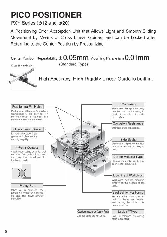
High Accuracy, High Rigidity Linear Guide is built-in.
Cross Linear Guide
Center Position Repeatability ±0.05mm, Mounting Parallelism 0.01mm
PXY Series (φ12 and φ20)
Side Seals
Corrosion Resistance
4-Point Contact
Centering
Steel Ball for Positioning
Stainless steel is adopted.
Center Holding Type
Lock-off TypeCountermeasure for Copper PartsCopper parts are not used.
Positioning Pin Holes
Mounting of Workpiece
Cross Linear Guide
Piping Port
2
PICO POSITIONER
A Positioning Error Absorption Unit that Allows Light and Smooth Sliding
Movement by Means of Cross Linear Guides, and can be Locked after
Returning to the Center Position by Pressurizing
Pin holes for attaching / detaching reproducibility are provided on the top surface of the body and the side surface of the table.
Limited track type linear guides of high-accuracy and high-rigidity.
4-point contact guide which well endures fluctuating load and combined load, is adopted for the linear guide.
When air is supplied. the piston will make the position-ing steel ball move towards the table.
The hole on the top of the body can be used for centering in relation to the hole on the table side surface.
Side seals are provided at four places to prevent the entry of dust.
Holding the center position by spring after exhausted.
Workpiece can be mounted directly on the surface of the table.
This ball is for returning of the table to the center position and locking the table at its center position.
Lock is released by spring after exhausted.
C
M
Y
CM
MY
CY
CMY
K
002-E.eps 1 2017/11/28 16:02:53002-E.eps 1 2017/11/28 16:02:53
Deviation
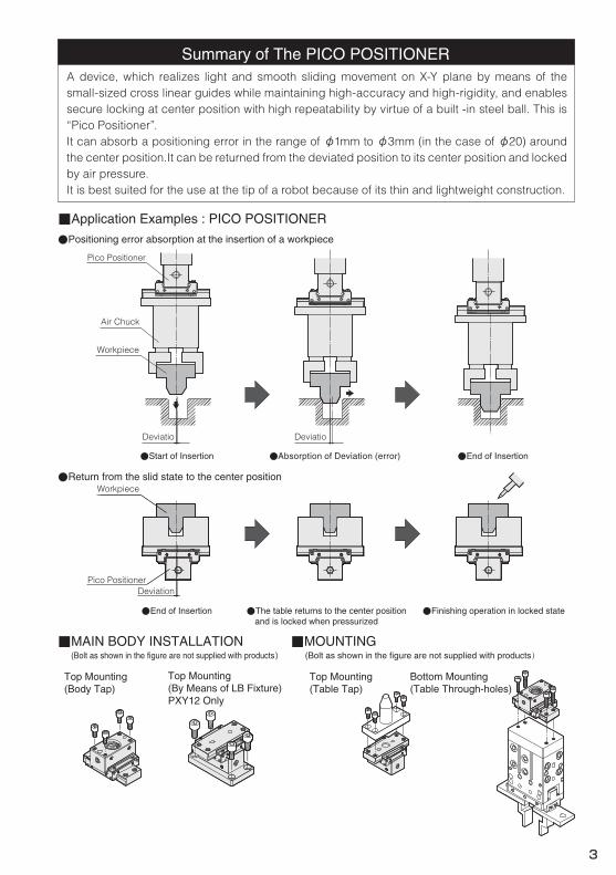
Summary of The PICO POSITIONER
■Application Examples : PICO POSITIONER
●Positioning error absorption at the insertion of a workpiece
Air Chuck
Workpiece
Pico Positioner
●Start of Insertion ●Absorption of Deviation (error) ●End of Insertion
●Return from the slid state to the center positionWorkpiece
Pico Positioner
●Finishing operation in locked state●End of Insertion ●The table returns to the center position and is locked when pressurized
DeviatioDeviatio
Top Mounting(Body Tap)
Top Mounting(By Means of LB Fixture)PXY12 Only
(Bolt as shown in the figure are not supplied with products)■MAIN BODY INSTALLATION
(Bolt as shown in the figure are not supplied with products)■MOUNTING
Bottom Mounting(Table Through-holes)
3
A device, which realizes light and smooth sliding movement on X-Y plane by means of the small-sized cross linear guides while maintaining high-accuracy and high-rigidity, and enables secure locking at center position with high repeatability by virtue of a built -in steel ball. This is “Pico Positioner”.It can absorb a positioning error in the range of φ1mm to φ3mm (in the case of φ20) around the center position.It can be returned from the deviated position to its center position and locked by air pressure.It is best suited for the use at the tip of a robot because of its thin and lightweight construction.
Top Mounting(Table Tap)
C
M
Y
CM
MY
CY
CMY
K
003-E.eps 1 2017/11/22 10:02:55003-E.eps 1 2017/11/22 10:02:55
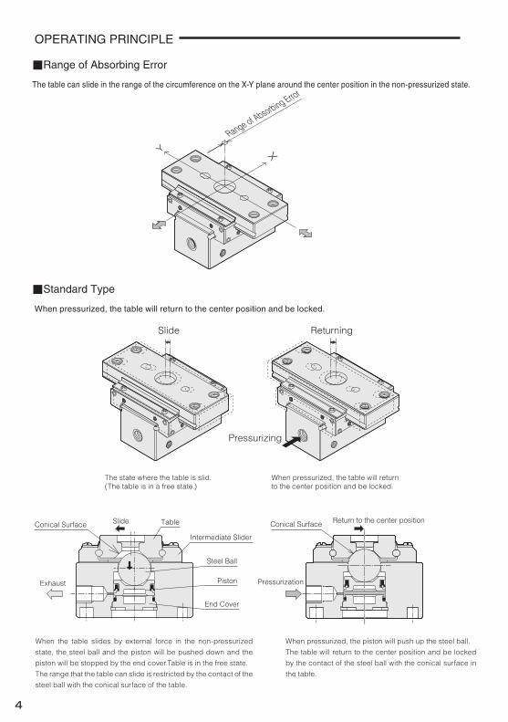
OPERATING PRINCIPLE
When pressurized, the table will return to the center position and be locked.
The table can slide in the range of the circumference on the X-Y plane around the center position in the non-pressurized state.
Range of Absorbing Error
XY
Pressurizing
ReturningSlide
The state where the table is slid.(The table is in a free state.)
When pressurized, the table will returnto the center position and be locked.
Pressurization
Return to the center positionConical Surface
■Range of Absorbing Error
■Standard Type
Conical Surface
End Cover
Piston
Steel Ball
Intermediate Slider
TableSlide
Exhaust
4
When the table slides by external force in the non-pressurized
state, the steel ball and the piston will be pushed down and the
piston will be stopped by the end cover.Table is in the free state.
The range that the table can slide is restricted by the contact of the
steel ball with the conical surface of the table.
When pressurized, the piston will push up the steel ball.
The table will return to the center position and be locked
by the contact of the steel ball with the conical surface in
the table.
C
M
Y
CM
MY
CY
CMY
K
004-E.eps 1 2017/11/29 9:03:54004-E.eps 1 2017/11/29 9:03:54
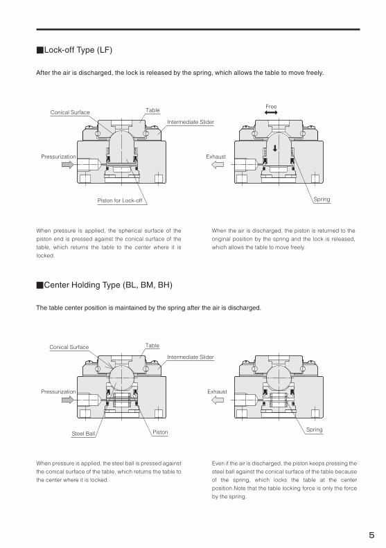
■Lock-off Type (LF)
■Center Holding Type (BL, BM, BH)
After the air is discharged, the lock is released by the spring, which allows the table to move freely.
The table center position is maintained by the spring after the air is discharged.
Piston for Lock-off Spring
Pressurization Exhaust
FreeTable
Intermediate Slider
Conical Surface
Pressurization Exhaust
TableConical Surface
Intermediate Slider
SpringPistonSteel Ball
5
When pressure is applied, the spherical surface of the
piston end is pressed against the conical surface of the
table, which returns the table to the center where it is
locked.
When the air is discharged, the piston is returned to the
original position by the spring and the lock is released,
which allows the table to move freely.
When pressure is applied, the steel ball is pressed against
the conical surface of the table, which returns the table to
the center where it is locked.
Even if the air is discharged, the piston keeps pressing the
steel ball against the conical surface of the table because
of the spring, which locks the table at the center
position.Note that the table locking force is only the force
by the spring.
C
M
Y
CM
MY
CY
CMY
K
005-E.eps 1 2017/11/22 10:38:12005-E.eps 1 2017/11/22 10:38:12
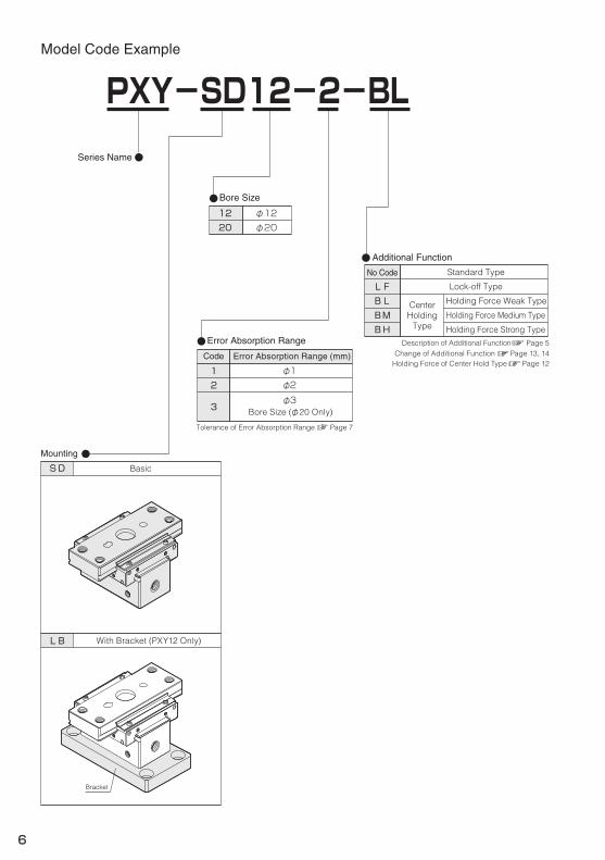
Bore Size
Series Name
SDMounting
12
Basic
PXY-SD12-2-BL
With Bracket (PXY12 Only)LB
Additional Function
Standard TypeNo Code
BLLF
BMBH
CenterHolding
Type
Lock-off Type
Error Absorption Range
Error Absorption Range (mm)
φ22φ3
Bore Size (φ20 Only)3
φ11Code
φ1220 φ20
Holding Force Medium Type
Holding Force Weak Type
Holding Force Strong Type
Bracket
Description of Additional Function Page 5Change of Additional Function Page 13, 14
Tolerance of Error Absorption Range Page 7
Model Code Example
6
Holding Force of Center Hold Type Page 12
C
M
Y
CM
MY
CY
CMY
K
006-E.eps 1 2017/11/22 10:57:09006-E.eps 1 2017/11/22 10:57:09
PXY12
5~60℃
φ12㎜
0.7MPa0.1MPa
Air Returning
Center Position Locking
1kg
1.05MPa
25Model
Note
Note
60c.p.m
Air
76NNot required
130
Unit : g
Model Type
32N
Mass added with Bracket
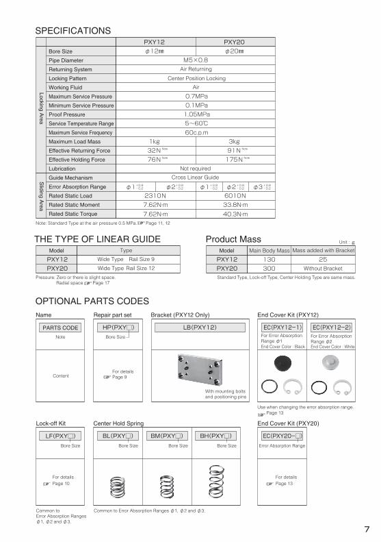
SPECIFICATIONS
THE TYPE OF LINEAR GUIDE Product Mass
PXY12 Wide Type Rail Size 9
PXY20 Without Bracket300PXY20 Wide Type Rail Size 12
Main Body Mass
2310N
Cross Linear Guide
7.62N・m7.62N・m
φ1+0.9-0.2 φ1+0.9-0.2 φ2+0.9-0.2 φ3+0.9-0.2
M5×0.8
φ2+0.9-0.2
φ20㎜PXY12 PXY20
3kg
Note
Note
175N91N
6010N33.8N・m40.3N・m
Standard Type, Lock-off Type, Center Holding Type are same mass.Pressure: Zero or there is slight space.Radial space Page 17
Note: Standard Type at the air pressure 0.5 MPa. Page 11, 12
OPTIONAL PARTS CODESName
Note
PARTS CODE
Content
End Cover Kit (PXY12)
EC(PXY12-1)
BL(PXY□) BM(PXY□)
Repair part set
HP(PXY□)
With mounting boltsand positioning pins
Bracket (PXY12 Only)
LB(PXY12)
BH(PXY□)
EC(PXY12-2)For Error AbsorptionRange φ1
For Error AbsorptionRange φ2
Lock-off Kit
LF(PXY□)
End Cover Color : Black End Cover Color : White
Common to Error Absorption Ranges φ1, φ2 and φ3.Common toError Absorption Rangesφ1, φ2 and φ3.
Use when changing the error absorption range. Page 13
For detailsPage 10
For detailsPage 13
End Cover Kit (PXY20)
EC(PXY20-□)Bore Size
Bore Size
Bore Size Bore Size Bore Size Error Absorption Range
7
Bore Size
Pipe Diameter
Returning System
Locking Pattern
Working Fluid
Maximum Service Pressure
Minimum Service Pressure
Proof Pressure
Service Temperature Range
Maximum Service Frequency
Maximum Load Mass
Effective Returning Force
Effective Holding Force
Lubrication
Guide Mechanism
Error Absorption Range
Rated Static Load
Rated Static Moment
Rated Static Torque
Center Hold Spring
Locking Area
Sliding A
rea
For detailsPage 9
C
M
Y
CM
MY
CY
CMY
K
007-E.eps 1 2017/11/28 16:15:53007-E.eps 1 2017/11/28 16:15:53
LH
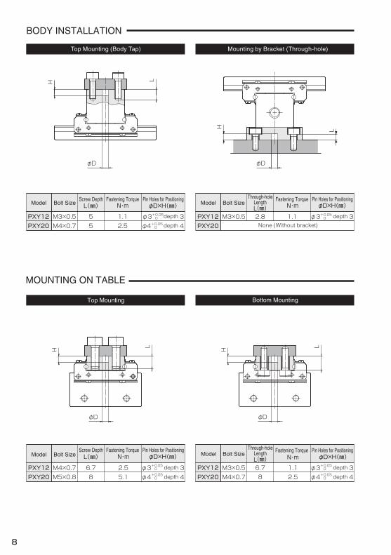
BODY INSTALLATION
MOUNTING ON TABLE
M3×0.5PXY12
φD×H(㎜)
φ3+0.05 depth 3 0
N・m
M4×0.7PXY12
φD×H(㎜)
φ3+0.05 depth 3 0
Model
M3×0.5PXY12
Bolt SizePin Holes for PositioningφD×H(㎜)
φ3+0.05 depth 30
Fastening TorqueN・mModel
Through-holeLengthL(㎜)
Screw DepthL(㎜)
M3×0.5PXY12
Bolt Size
5
φD×H(㎜)
φ3+0.05 depth 30
N・m
φD φD
LH
φD
LH
φD
LH
L(㎜) N・m
6.7 2.5 6.7 1.1M4×0.7PXY20 φ4+0.05 depth 4 0M5×0.8PXY20 φ4+0.05 depth 4 08 5.1 8 2.5
1.1 2.8 1.1None (Without bracket) PXY20M4×0.7PXY20 5 φ4+0.05 depth 402.5
8
Fastening Torque Pin Holes for Positioning
Model Bolt SizeScrew Depth Fastening Torque Pin Holes for Positioning
Bolt SizePin Holes for PositioningFastening Torque
ModelThrough-hole
LengthL(㎜)
Bottom MountingTop Mounting
Mounting by Bracket (Through-hole)Top Mounting (Body Tap)
C
M
Y
CM
MY
CY
CMY
K
008-E.eps 1 2017/11/28 16:20:54008-E.eps 1 2017/11/28 16:20:54
18
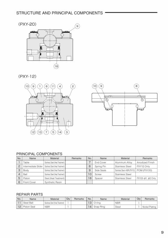
STRUCTURE AND PRINCIPAL COMPONENTS
(PXY-20)
(PXY-12)
PRINCIPAL COMPONENTS
3
72
Name Material Remarks
1No. Name Material RemarksNo.
8
REPAIR PARTS
1311Remarks
14
Qty
111
49
56
1018
12 1
10 111 2469 10 89
12 13 14 357
9
9
Table
Intermediate Slider
Body
Ball
Piston
Front Cover
Stainless Steel (Heat Treatment)
Stainless Steel (Heat Treatment)
Stainless Steel (Heat Treatment)
Stainless Steel (Heat Treatment)
Steel (Heat Treatment)
Synthetic Resin
Steel Ball
Piston Seal
Stainless Steel (Heat Treatment)
NBR
O-ring
Snap Ring
NBR
Steel Nickel Plating
End Cover
Spring Pin
Side Seals
Screw
Spacer
Aluminum Alloy
Stainless Steel
Stainless Steel+NBR (PXY12)
Stainless Steel
Stainless Steel
Anodized Finish
PXY12 Only
POM (PXY20)
PXY20-φ1, φ2 Only
Name MaterialNo. RemarksQtyName MaterialNo.
C
M
Y
CM
MY
CY
CMY
K
009-E.eps 1 2017/11/22 11:56:40009-E.eps 1 2017/11/22 11:56:40
Spring for Center Holding
Lock-off Kit
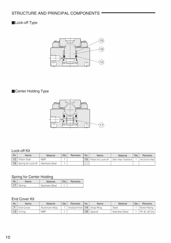
■Lock-off Type
■Center Holding Type
1215
Remarks
11
161
End Cover Kit
713
111 14
118
17 1
12
15
16
17
STRUCTURE AND PRINCIPAL COMPONENTS
10
QtyName MaterialNo.
RemarksQtyName MaterialNo.
RemarksQtyName MaterialNo. RemarksQtyName MaterialNo.
Piston Seal
Spring for Lock-off
NBR
Stainless Steel
End Cover
O-ring
Aluminum Alloy
NBR
Snap Ring
Spacer
Steel
Stainless Steel
Nickel Plating
PXY φ1, φ2 Only
Anodized Finish
Piston for Lock-off Steel (Heat Treatment) Hard Chromium Plated
Spring Stainless Steel
RemarksQtyName MaterialNo.
C
M
Y
CM
MY
CY
CMY
K
010-E.eps 1 2017/11/22 13:12:57010-E.eps 1 2017/11/22 13:12:57
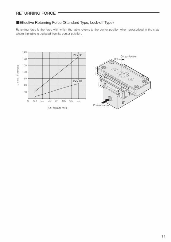
RETURNING FORCE
■Effective Returning Force(Standard Type, Lock-off Type)
Pressurization
Return
0 0.2 0.70.3 0.4
Air Pressure MPa
0.5 0.60.1
40
60
80
100
120
140
20
PXY20
PXY12
11
Returning force is the force with which the table returns to the center position when pressurized in the state where the table is deviated from its center position.
Returning
Force N
Center Position
C
M
Y
CM
MY
CY
CMY
K
011-E.eps 1 2017/11/28 16:23:58011-E.eps 1 2017/11/28 16:23:58
Body
Table
Table
40g 90gTable
PXY12PXY12 PXY20
Body 65g 155g
PXY12 PXY20
Intermediate Slider
Intermediate Slider
40g25g
PXY2090g55g
BLBMBH
Option Code
PXY12
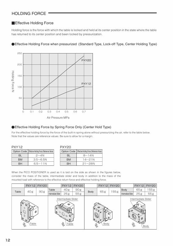
2~4N3.5~6.5N6.5~11N
BLBMBH
Option Code
PXY20
8~14N14~21N21~28N
Effective Holding Force (Reference Value)
●Effective Holding Force when pressurized (Standard Type, Lock-off Type, Center Holding Type)
●Effective Holding Force by Spring Force Only (Center Hold Type)
50
0 0.2 0.70.3 0.4 0.5 0.60.1
200
150
100
250
■Effective Holding Force
BodyTable
Intermediate Slider
HOLDING FORCE
PXY20
PXY12
Body
PXY1265g
PXY20155g
25g 55g
12
For the effective holding force by the force of the built-in spring alone without pressurizing the air, refer to the table below.
Note that the values are reference values. Be sure to allow for a margin.
When the PICO POSITIONER is used as it is laid on the side as shown in the figures below,
consider the mass of the table, intermediate slider and body in addition to the mass of the
mounted load with reference to the effective return force and effective holding force.
Intermediate Slider
Holding force is the force with which the table is locked and held at its center position in the state where the table has returned to its center position and been locked by pressurization.
Hold
ing Force N
Air Pressure MPa
Effective Holding Force (Reference Value)
C
M
Y
CM
MY
CY
CMY
K
012-E.eps 1 2017/11/22 13:25:35012-E.eps 1 2017/11/22 13:25:35
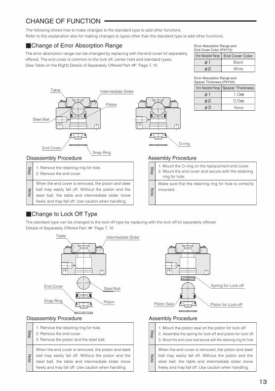
■Change of Error Absorption Range
■Change to Lock Off Type
Disassembly Procedure Assembly Procedure
Assembly ProcedureDisassembly Procedure
φ1 Black
White
End Cover ColorError Absorption Range
φ2
Error Absorption Range andSpacer Thickness (PXY20)
φ1 1.0㎜0.5㎜
Spacer ThicknessError Absorption Range
φ2Noneφ3
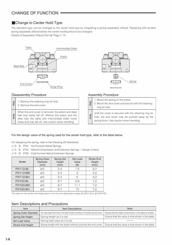
1. Remove the retaining ring for hole.
2. Remove the end cover.
Steel Ball
Piston
End Cover
Snap Ring
Table Intermediate Slider
Spring for Lock-off
Piston for Lock-offPiston Seal
CHANGE OF FUNCTION
O-ringEnd Cover
Snap Ring
Table Intermediate Slider
Steel Ball
Piston
13
The following shows how to make changes to the standard type to add other functions.
Refer to this explanation also for making changes to types other than the standard type to add other functions.
The error absorption range can be changed by replacing with the end cover kit separately
offered. The end cover is common to the lock off, center hold and standard types.
(See Table on the Right) Details of Separately Offered Part Page 7, 10
When the end cover is removed, the piston and steel
ball may easily fall off. Without the piston and the
steel ball, the table and intermediate slider move
freely and may fall off. Use caution when handling.
1. Mount the O-ring on the replacement end cover.2. Mount the end cover and secure with the retaining ring for hole.
Make sure that the retaining ring for hole is correctly
mounted.
1. Remove the retaining ring for hole.
2. Remove the end cover.
3. Remove the piston and the steel ball.
When the end cover is removed, the piston and steel
ball may easily fall off. Without the piston and the
steel ball, the table and intermediate slider move
freely and may fall off. Use caution when handling.
1. Mount the piston seal on the piston for lock off.
2. Assemble the spring for lock off and piston for lock off.
3. Mount the end cover and secure with the retaining ring for hole.
When the end cover is removed, the piston and steel
ball may easily fall off. Without the piston and the
steel ball, the table and intermediate slider move
freely and may fall off. Use caution when handling.
Error Absorption Range andEnd Cover Color (PXY12)
The standard type can be changed to the lock off type by replacing with the lock off kit separately offered.
Details of Separately Offered Part Page 7, 10
Step
Note
Step
Note
Step
Note
Step
Note
C
M
Y
CM
MY
CY
CMY
K
013-E.eps 1 2017/11/28 16:29:07013-E.eps 1 2017/11/28 16:29:07
Item Descriptions and Precautions
PXY12-BMPXY12-BL φ6 5.4 1.5
PXY12-BH
Disassembly Procedure
■Change to Center Hold Type
Assembly Procedure
φ6φ6
5.45.4
36
4.24.24.2
PXY20-BL φ6 8.7 4.8 7.2PXY20-BM φ6 8.7 11.1 7.2PXY20-BH φ6 8.7 15 7.2
Item Item Descriptions Note
Model
For designing the spring, refer to the following JIS Standards.
J I S B 2702 Hot Formed Helical Springs
J I S B 2704 Helical Compression and Extension Springs -- Design Criteria
J I S B 2708 Cold Formed Helical Extension Springs
For the design value of the spring used for the center hold type, refer to the table below.
Spring OuterDiameter
(mm)
Spring SetHeight(mm)
Stroke EndHeight(mm)
Set LoadValue
(N)
Any value larger than those in the table hinders mounting on the piston and end cover.
Spring length as it is set.
Spring load value as it is set.
Spring length with the piston directly touches the end cover.
Ensure that the value is that shown in the table or smaller.
Ensure that the value is that shown in the table.
Ensure that the value is that shown in the table.
End CoverSnap Ring
Table Intermediate Slider
Steel Ball
Piston
Spring
The value for the stroke end height given is for the error absorption range φ2 (PXY12) or φ3 (PXY20).
CHANGE OF FUNCTION
14
The standard type can be changed to the center hold type by integrating a spring separately offered. Replacing with another
spring separately offered allows the center holding force to be changed.
Details of Separately Offered Part Page 7, 10
1. Remove the retaining ring for hole.
2. Remove the end cover.
When the end cover is removed, the piston and steel ball may easily fall off. Without the piston and the steel ball, the table and intermediate slider move freely and may fall off. Use caution when handling.
1. Mount the spring on the piston.
2. Mount the end cover and secure with the retaining
ring for hole.
Until the cover is secured with the retaining ring for
hole, the end cover may be pushed away by the
spring force. Use caution when handling.
Spring Outer Diameter
Spring Set Height
Set Load Value
Stroke End Height
Step
Note
Step
Note
C
M
Y
CM
MY
CY
CMY
K
014-E.eps 1 2017/11/28 16:30:08014-E.eps 1 2017/11/28 16:30:08
MATTERS TO BE NOTED FOR DESIGNING AND OPERATION
Warning
B
A R0.2 or less
R0.2 or less
A
B
BA
θ°
θ°
Failure of Power Supply and Abnormal Condition of Supply Pressure
Range of Positioning Error Absorption
Shock Absorption at Stopping
Resistance of Piping and Wiring
Removal of Pico Positioner
At Operation
Setting of Covers
Mounting and Adjustment
Rigidity of Mounting Base
Mounting Surface Accuracy
①
②
③
④
Rolling Feel in Linear Guide
PICO POSITONER Movement
Positioning Pin Holes in Table and Body
15
If supply pressure goes up/ down abnormally due to failure or
other troubles of power sources such as electricity or air
pressure. returning and holding forces of Pico Positioner will
also change accordingly and malfunction may occur. Take
necessary measures against this situation not to hurt human
or damage devices.
An error beyond this range will generate excessively large
load or moment to cause failure of Pico Positioner or breakage
of a workpiece.
In the case Pico Positioner is moved straight or turned around
by a robot or another actuator. and stopped suddenly. the lock
may be unlatched or the linear guide may be broken due to
excessively large inertia force. Shock absorption by cushion-
ing, shock absorbers, etc. shall be considered on designing.
Smooth movement of Pico Positioner may be hindered by the
resistance of piping or wiring. Consider the resistance against
smooth operation in the design stage.
When the Pico Positioner is to be removed from a device for
modification or maintenance, shut off the supply of compressed
air and discharge the residual pressure.
When actuator is in operation or power supply is not shut off.
never put your fingers. hands. tools, etc. into the moving area
of devices or Pico Positioner inadvertently to prevent injury or
accident.
If water. oil, cutting fluid, dust. iron powder, spatter. etc. are
deposited on the linear guides, damage, rust, etc. may occur
to cause malfunction. Set covers on the linear guides to
prevent such deposition.
When mounting a workpiece on the guide table, support the
workpiece with a wrench, etc. to prevent any load or impact
applied to the table.
If rigidity of mounting base or mounting method of Pico
Positioner on the machinery is not adequate, it may be
impossible for Pico Positioner to demonstrate its high-rigidity
and high-accuracy.
On designing, due consideration shall be given to rigidity of
machinery such as mounting base.
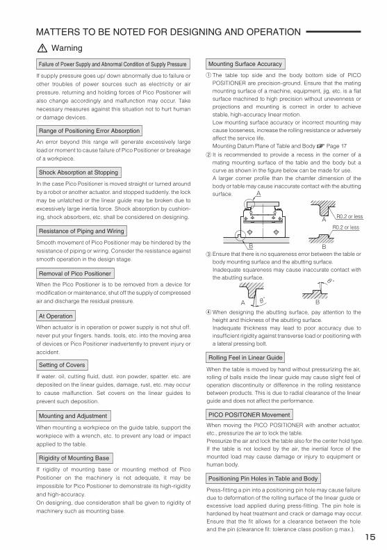
The table top side and the body bottom side of PICO POSITIONER are precision-ground. Ensure that the mating mounting surface of a machine, equipment, jig, etc. is a flat surface machined to high precision without unevenness or projections and mounting is correct in order to achieve stable, high-accuracy linear motion. Low mounting surface accuracy or incorrect mounting may cause looseness, increase the rolling resistance or adversely affect the service life.Mounting Datum Plane of Table and Body Page 17
It is recommended to provide a recess in the corner of a mating mounting surface of the table and the body but a curve as shown in the figure below can be made for use.A larger corner profile than the chamfer dimension of the body or table may cause inaccurate contact with the abutting surface.
Ensure that there is no squareness error between the table or body mounting surface and the abutting surface. Inadequate squareness may cause inaccurate contact with the abutting surface.
When designing the abutting surface, pay attention to the height and thickness of the abutting surface. Inadequate thickness may lead to poor accuracy due to insufficient rigidity against transverse load or positioning with a lateral pressing bolt.
When the table is moved by hand without pressurizing the air, rolling of balls inside the linear guide may cause slight feel of operation discontinuity or difference in the rolling resistance between products. This is due to radial clearance of the linear guide and does not affect the performance.
When moving the PICO POSITIONER with another actuator, etc., pressurize the air to lock the table. Pressurize the air and lock the table also for the center hold type. If the table is not locked by the air, the inertial force of the mounted load may cause damage or injury to equipment or human body.
Press-fitting a pin into a positioning pin hole may cause failure due to deformation of the rolling surface of the linear guide or excessive load applied during press-fitting. The pin hole is hardened by heat treatment and crack or damage may occur. Ensure that the fit allows for a clearance between the hole and the pin (clearance fit: tolerance class position g max.).
C
M
Y
CM
MY
CY
CMY
K
015-E.eps 1 2017/11/22 15:02:27015-E.eps 1 2017/11/22 15:02:27
Caution
L
MATTERS TO BE NOTED FOR DESIGNING AND OPERATION
Greasing
Moment by the Returning Force
●Generation of a Large Moment●Possibility of Damage of a Workpiece
Moment
Returning ForceReturning Force
Area to be greasedArea to be greased
Area to be greasedArea to be greased
Workpiece Workpiece
Air Chuck Air Chuck
DeviationDeviation
Table Slide Resistance (Standard Type)
16
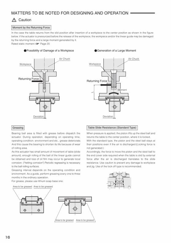
In the case the table returns from the slid position after insertion of a workpiece to the center position as shown in the figure
below. if the actuator is pressurized before the release of the workpiece, the workpiece and/or the linear guide may be damaged
by the returning force and a large moment generated by it.
Rated static moment Page 20
Bearing ball area is filled with grease before dispatch the
actuator. During operation. depending on operating time,
operating condition. environment and etc., grease deteriorate.
And this cause the bearing to shorten its life because of wear
of rolling area.
As this actuator has small amount of movement of table (slide
amount), enough rolling of the ball of the linear guide cannot
be obtained and loss of oil film may occur to generate local
corrosion. ("fretting corrosion") Periodic regreasing is necessary
to the ball rolling surfaces.
Greasing interval depends on the operating condition and
environment. As a guide, perform greasing every one to three
months in the ordinary operation.
For grease, please use lithium soap base one.
When pressure is applied, the piston lifts up the steel ball and
returns the table to the center position, where it is locked.
With the standard type, the piston and the steel ball stays at
their positions even if the air is discharged.(Locking force is
not generated.)
Accordingly, the force to move the piston and the steel ball to
the end cover side required when the table is slid by external
force after the air is discharged translates to the slide
resistance. Use caution to prevent any damage to workpiece
and jig. Use of the lock off type is recommended.
C
M
Y
CM
MY
CY
CMY
K
016-E.eps 1 2017/11/22 15:14:28016-E.eps 1 2017/11/22 15:14:28
Accuracy
■Bearing Accuracy
PXY12
Unit : mm
Model
0.01
■Radial Clearance
PXY12・PXY200~+0.004
Model
Radial Clearance
Unit : mm
Radial Clearance
E
C
D
0.01
±0.05
0-0.1
0-0.1
PXY200.010.01
±0.08
0-0.1
0-0.1
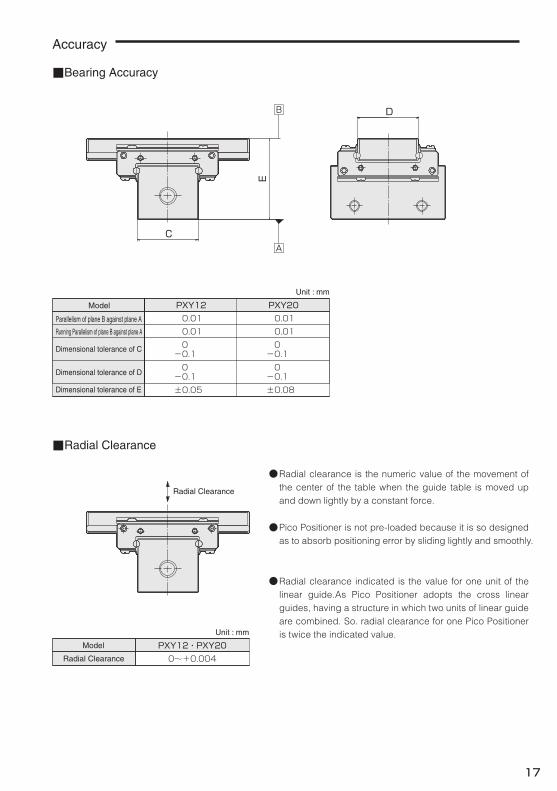
●Radial clearance is the numeric value of the movement of the center of the table when the guide table is moved up and down lightly by a constant force.
Pico Positioner is not pre-loaded because it is so designed as to absorb positioning error by sliding lightly and smoothly.
Radial clearance indicated is the value for one unit of the linear guide.As Pico Positioner adopts the cross linear guides, having a structure in which two units of linear guide are combined. So. radial clearance for one Pico Positioner is twice the indicated value.
●
●
17
Parallelism of plane B against plane A
Running Parallelism of plane B against plane A
Dimensional tolerance of C
Dimensional tolerance of D
Dimensional tolerance of E
C
M
Y
CM
MY
CY
CMY
K
017-E.eps 1 2017/11/22 15:23:22017-E.eps 1 2017/11/22 15:23:22
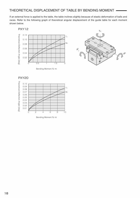
PXY12
M0
0.02
0.04
0.06
0.08
0.10
0.12
0 20.5 1 1.5
Bending Moment N・m
T0
PXY20
M0
0.100.090.080.070.060.050.040.030.020.01
0 8 102 4 6
T0
THEORETICAL DISPLACEMENT OF TABLE BY BENDING MOMENT
T0
M0M0
18
If an external force is applied to the table, the table inclines slightly because of elastic deformation of balls and races. Refer to the following graph of theoretical angular displacement of the guide table for each moment shown below.
Bending Moment N・mTheoretical D
eflection Ang
le [deg
]Theoretical D
eflection Ang
le [deg
]
C
M
Y
CM
MY
CY
CMY
K
018-E.eps 1 2017/11/28 16:31:11018-E.eps 1 2017/11/28 16:31:11
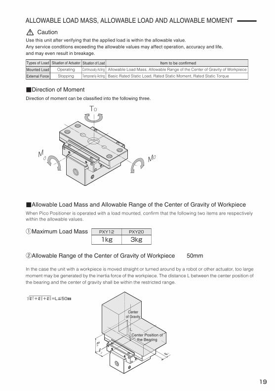
ALLOWABLE LOAD MASS, ALLOWABLE LOAD AND ALLOWABLE MOMENT
■Allowable Load Mass and Allowable Range of the Center of Gravity of Workpiece
Direction of moment can be classified into the following three.
■Direction of Moment
②Allowable Range of the Center of Gravity of Workpiece 50mm
Operating
Stopping
Situation of Actuator Situation of Load
Continuously Acting
Temporarily Acting
Types of Load
Mounted Load
External Force Basic Rated Static Load, Rated Static Moment, Rated Static Torque
Item to be confirmed
Caution
①Maximum Load Mass
ℓ2 1+ℓ2
2+ℓ2 3=L≦50㎜
T0
M0 M0
ℓ1ℓ2
ℓ3
Use this unit after verifying that the applied load is within the allowable value.Any service conditions exceeding the allowable values may affect operation, accuracy and life,and may even result in breakage.
When Pico Positioner is operated with a load mounted, confirm that the following two items are respectivelywithin the allowable values.
LL
PXY12
1kgPXY20
3kg
19
Allowable Load Mass, Allowable Range of the Center of Gravity of Workpiece
In the case the unit with a workpiece is moved straight or turned around by a robot or other actuator, too large moment may be generated by the inertia force of the workpiece. The distance L between the center position of the bearing and the center of gravity shall be within the restricted range.
Center Position ofthe Bearing
Centerof Gravity
C
M
Y
CM
MY
CY
CMY
K
019-E.eps 1 2017/11/28 16:35:32019-E.eps 1 2017/11/28 16:35:32
ALLOWABLE LOAD MASS, ALLOWABLE LOAD AND ALLOWABLE MOMENT
7.62
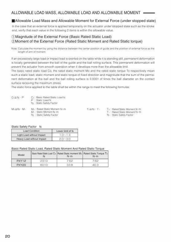
■Allowable Load Mass and Allowable Moment for External Force (under stopped state)
C0≧fs・P
T0≧fs・T1
Static Safety Factor fsLoad Condition
Light Load without Impact
Heavy Load without Impact 2.0~3.01.0~1.3
Lower limit of fs
Basic Rated Static Load C0N N・m
Basic Rated Static Load, Rated Static Moment And Rated Static Torque
①Magnitude of the External Force (Basic Rated Static Load)②Moment of the External Force (Rated Static Moment and Rated Static torque)
Model
PXY12 2310 7.6240.3PXY20 6010 33.8
M0≧fs・M1
Rated Static Torque T0Rated Static moment M0N・m
C0Pfs
M0M1fs
:Basic Rated Static Load N:Static Load N:Static Safety Factor
:Rated Static Moment N・m:Static Moment N・m:Static Safety Factor
T0T1fs
:Rated Static Moment N・m:Rated Static Moment N・m:Static Safety Factor
20
In the case that an external force is applied temporarily on the actuator under stopped state such as the stroke end, verify that each value in the following 2 items is within the allowable value.
If an excessively large load or impact load is exerted on the table while it is standing still, permanent deformation is locally generated between the ball of the guide and the ball rolling surface. This permanent deformation will prevent the actuator from smooth operation when it develops more than the allowable limit.The basic rated static load Co, the rated static moment Mo and the rated static torque To respectively mean such a static load, static moment and static torque of fixed direction and magnitude that the sum of the perma-nent deformation at the ball and the ball rolling surface is 0.0001 of times the ball diameter on the contact surface receiving the maximum stress.The static force applied to the table shall be within the range to meet the following formulas.
Note: Calculate the moment by using the distance between the center position of guide and the position of external force as the length of arm of moment.
C
M
Y
CM
MY
CY
CMY
K
020-E.eps 1 2017/11/22 16:35:04020-E.eps 1 2017/11/22 16:35:04
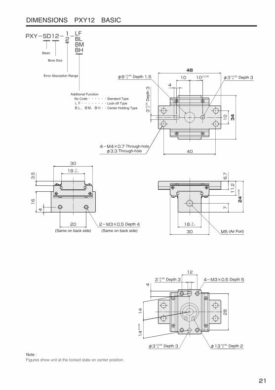
DIMENSIONS PXY12 BASIC
Basic
Bore Size
PXY-SD12- -LFBLBMBH
Additional FunctionNo Code・・・・・・Standard TypeLF・・・・・・・・Lock-off Type
Error Absorption Range
12
BL,BM,BH・・Center Holding Type
Note :Figures show unit at the locked state on center position.
(Same on back side)(Same on back side)
6.7
11.2
24±0.05
718 0
-0.1
30
10 10±0.05
10
48
4
3+0.05 D
epth
30
40
φ3+0.05 Depth 30φ8+0.05 Depth 1.50
16
30
20
4
34
18 0-0.1
4-M4×0.7 Through-holeφ3.3 Through-hole
M5 (Air Port)
3.5
2-M3×0.5 Depth 4
12
28
4-M3×0.5 Depth 53+0.05 Depth 30
4
14±0.05
14
φ3+0.05 Depth 30 φ13+0.05 Depth 20
21
C
M
Y
CM
MY
CY
CMY
K
021-E.eps 1 2017/11/22 16:54:50021-E.eps 1 2017/11/22 16:54:50
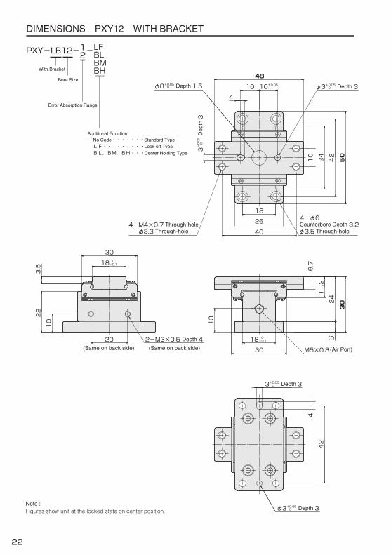
DIMENSIONS PXY12 WITH BRACKET
With Bracket
PXY-LB12- -
Note :Figures show unit at the locked state on center position.
(Same on back side) (Same on back side)
42
50
4
6
18
26
10
34
10 10±0.0548
4
φ8+0.05 Depth 1.50 φ3+0.05 Depth 30
3+0.05 D
epth
30
404-M4×0.7 Through-holeφ3.3 Through-hole
3024
11.2
6.7
30
18 0-0.1
3.5
20 2-M3×0.5 Depth 4 18 0-0.1
30 M5×0.8 (Air Port)
4-φ6Counterbore Depth 3.2φ3.5 Through-hole
22
10 13
3+0.05 Depth 30
42
φ3+0.05 Depth 30
Bore Size
LFBLBMBH
Additional FunctionNo Code・・・・・・・Standard TypeLF・・・・・・・・・Lock-off Type
Error Absorption Range
12
BL,BM,BH・・・Center Holding Type
22
C
M
Y
CM
MY
CY
CMY
K
022-E.eps 1 2017/11/28 16:37:38022-E.eps 1 2017/11/28 16:37:38
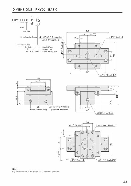
Basic
Bore Size
PXY-SD20- -LFBLBMBH
Additional FunctionNo Code・・・・・・・Standard TypeLF・・・・・・・・・Lock-off TypeBL,BM,BH・・・Center Holding Type
Error Absorption Range
123
Note :Figures show unit at the locked state on center position.
(Same on back side) (Same on back side)8
14
31±0.08
8.524 0
-0.1
40
13 13±0.05
14
68
5
4+0.05 D
epth
40
58
φ4+0.05 Depth 40
φ8+0.05 Depth 1.50
21.9
40
25
6
46
24 0-0.1
4-M5×0.8 Through-hole
φ4.2 Through-hole
M5×0.8 (Air Port)
3.1
2-M4×0.7 Depth 5
16
38
4-M4×0.7 Depth 54+0.05 Depth 40
519±0.05
19
φ4+0.05 Depth 40 φ21+0.04 Depth 2.20
23
DIMENSIONS PXY20 BASIC
C
M
Y
CM
MY
CY
CMY
K
023-E.eps 1 2017/11/22 17:14:08023-E.eps 1 2017/11/22 17:14:08

PICO POSITIONER PXY Series
Error Absorption UnitPico Positioner Has Added A New Size!
Bore Size φ20!! (Conventional Product φ12)Bore Size φ20!! (Conventional Product φ12)Bore Size φ20!! (Conventional Product φ12)
FeaturesMaximum Load Mass
3kgMounting Parallelism
0.01mmRated Static Load
6010NIssued by
CAT NO. PXY-20 18-01
Home Page Address
E-mail Address
http://www.newera.co.jp/en/pneumatic/index.html
2016
http://www.newera.co.jp/en/pneumatic/index.html
RoHS Compliant
Top Related