


γλώσσες
Σελίδες
Νομικός

Multicasting and groupcastingwith physical layer constraintsin metropolitan optical networkswith mesh topologies.
Coordinator: Dr. Georgios EllinasParticipating Personnel: Dr. Georgios Ellinas, TaniaPanayiotou, Dr. Antonis Hadjiantonis, Antonis LambrouYoung Researcher: Tania Panayiotou
ΠΕΝΕΚ ΕΝΙΣΧ/0308 Mid-Project Report, 22 July 2010
Young Researcher: Tania Panayiotou
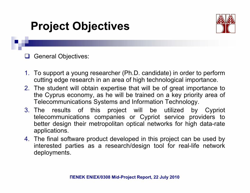
Project Objectives
General Objectives:
1. To support a young researcher (Ph.D. candidate) in order to performcutting edge research in an area of high technological importance.
2. The student will obtain expertise that will be of great importance tothe Cyprus economy, as he will be trained on a key priority area ofTelecommunications Systems and Information Technology.
3 Th lt f thi j t ill b tili d b C i t3. The results of this project will be utilized by Cypriottelecommunications companies or Cypriot service providers tobetter design their metropolitan optical networks for high data-rateapplications.pp
4. The final software product developed in this project can be used byinterested parties as a research/design tool for real-life networkdeployments.
ΠΕΝΕΚ ΕΝΙΣΧ/0308 Mid-Project Report, 22 July 2010
Project Objectives
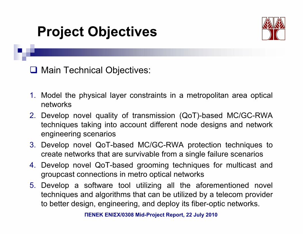
Main Technical Objectives:Main Technical Objectives:
1. Model the physical layer constraints in a metropolitan area opticalt knetworks
2. Develop novel quality of transmission (QoT)-based MC/GC-RWAtechniques taking into account different node designs and network
i i iengineering scenarios3. Develop novel QoT-based MC/GC-RWA protection techniques to
create networks that are survivable from a single failure scenarios4. Develop novel QoT-based grooming techniques for multicast and
groupcast connections in metro optical networks5. Develop a software tool utilizing all the aforementioned novel
techniques and algorithms that can be utilized by a telecom providerto better design, engineering, and deploy its fiber-optic networks.
ΠΕΝΕΚ ΕΝΙΣΧ/0308 Mid-Project Report, 22 July 2010

Time Schedule (1/2)
ΠΕΝΕΚ ΕΝΙΣΧ/0308 Mid-Project Report, 22 July 2010
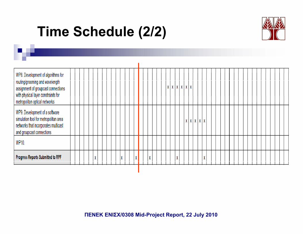
Time Schedule (2/2)
ΠΕΝΕΚ ΕΝΙΣΧ/0308 Mid-Project Report, 22 July 2010

Work Package 1:Project Managementj g
Deliverables for the first 15 months:• First two six-month reports• D1:Development of algorithms for routing/grooming and
wavelength assignment of protected multicast connections.D2: Mid project Report• D2: Mid-project Report
Accomplishments for the first 15 monthsDuring the first 15 months WPs 3-5 and deliverables D1, D2,were successfully completedwere successfully completed
Several novel algorithms, node designs, and network engineeringtechniques have been developed for QoT-based multicastprovisioning.
3 publications completed (1 journal paper and 2 conference3 publications completed (1 journal paper and 2 conferencepapers) with another 3 journal publications to be submittedshortlyWork was presented in two international conferences, includingth t ti i f ti l t kthe most prestigious conference on optical networksA web site for the project has been set up.
ΠΕΝΕΚ ΕΝΙΣΧ/0308 Mid-Project Report, 22 July 2010
Work Package 2:Dissemination and Exploitation of Results
Publications:
• G. Ellinas, N. Antoniades, T. Panayiotou, A. Hadjiantonis, andA.M. Levine, “Multicasting Routing Algorithms Based on Q-FactorPhysical Layer Constraints in Metro” IEEE/OSA PhotonicsPhysical Layer Constraints in Metro , IEEE/OSA PhotonicsTechnology Letters, vol. 21, no. 6, pp. 365-367, 2009.
• T. Panayiotou, G. Ellinas, N. Antoniades, A. M. Levine, “Designingand Engineering Metropolitan Area Transparent Optical Networksg g p p pfor the Provisioning of Multicast Sessions”, IEEE/OSA OpticalFiber Communications (OFC) Conference, San Diego, CA, March2010.T P i t G Elli N A t i d d A H dji t i• T. Panayiotou, G. Ellinas, N. Antoniades, and A. Hadjiantonis,“Node Architecture Design and Network Engineering Impact onOptical Multicasting Based on Physical Layer Constraints”, in Proc.International Conference on Transparent Optical NetworksInternational Conference on Transparent Optical Networks(ICTON), Munich, Germany, June/July 2010.
ΠΕΝΕΚ ΕΝΙΣΧ/0308 Mid-Project Report, 22 July 2010
Work Package 2:Dissemination and Exploitation of Results
Under Preparation:
• T. Panayiotou, G. Ellinas, A. Hadjiantonis, and N. Antoniades, “On theEffect of Node Architecture/Engineering for Multicasting Based on PhysicalLayer Constraints”, (under preparation), 2010. (Scheduled for submission tothe IEEE/OSA Journal of Lightwave Technology)the IEEE/OSA Journal of Lightwave Technology)
• T. Panayiotou, G. Ellinas, A. Hadjiantonis, and N. Antoniades, “MulticastProtection in Metro Networks Based on Physical Layer Constraints”, (underpreparation), 2010. (Scheduled for submission to the IEEE PhotonicsTechnology Letters)Technology Letters).
• T. Panayiotou, G. Ellinas, A. Hadjiantonis, and N. Antoniades, “MulticastGrooming in Metro Networks Based on Physical Layer Constraints”, (underpreparation), 2010. (Scheduled for submission to the IEEE/OSA Journal ofOptical Communications and Networking).Optical Communications and Networking).
A website is set up on which key results and project info are displayed(http://www eng ucy ac cy/gellinas/MULTIOPTI html)(http://www.eng.ucy.ac.cy/gellinas/MULTIOPTI.html)
ΠΕΝΕΚ ΕΝΙΣΧ/0308 Mid-Project Report, 22 July 2010
Work Package 3Development of RWA algorithms for multicast connections with PLCs (5-month duration)
D l t f Q b d ti d l f t lit ti l t k
PLCs (5 month duration)
Development of a Q-budgeting model for metropolitan optical networks.Development of a simulation code which performs the routing and thewavelength assignment under physical layer constraints.Development of new routing techniques for multicast connections which takeinto account physical layer constraints, such as:
BLT-Q heuristicBLT-Q tolerance heuristicMax Degree Node heuristic
And their performance was compared with existing routing algorithms:Steiner Tree heuristicShortest paths Tree heuristicBLT heuristicDAC heuristicMHP tree heuristicThat take only power budget constraints into account.
Development and examination of different Node Architectures andpEngineering Designs
ΠΕΝΕΚ ΕΝΙΣΧ/0308 Mid-Project Report, 22 July 2010
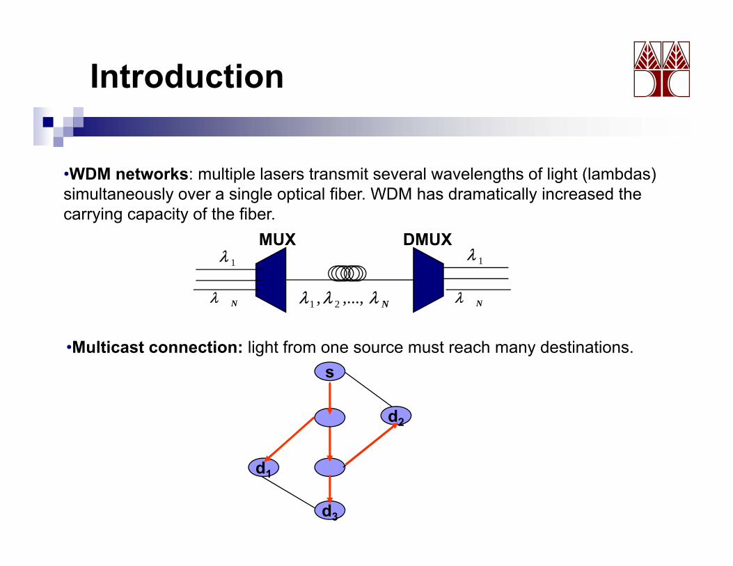
Introduction
•WDM networks: multiple lasers transmit several wavelengths of light (lambdas)
MUX DMUX
WDM networks: multiple lasers transmit several wavelengths of light (lambdas) simultaneously over a single optical fiber. WDM has dramatically increased the carrying capacity of the fiber.
1λ
Nλλλ ,...,, 21
1λ
Nλ Nλ
•Multicast connection: light from one source must reach many destinations.s
d2
d
d3
d1
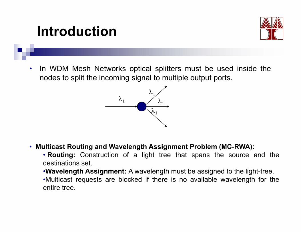
Introduction
• In WDM Mesh Networks optical splitters must be used inside thep pnodes to split the incoming signal to multiple output ports.
λ1
λ1λ1 λ1
λ1
• Multicast Routing and Wavelength Assignment Problem (MC-RWA):• Routing: Construction of a light tree that spans the source and thedestinations set.•Wavelength Assignment: A wavelength must be assigned to the light-tree.•Multicast requests are blocked if there is no available wavelength for theentire tree.entire tree.
Introduction
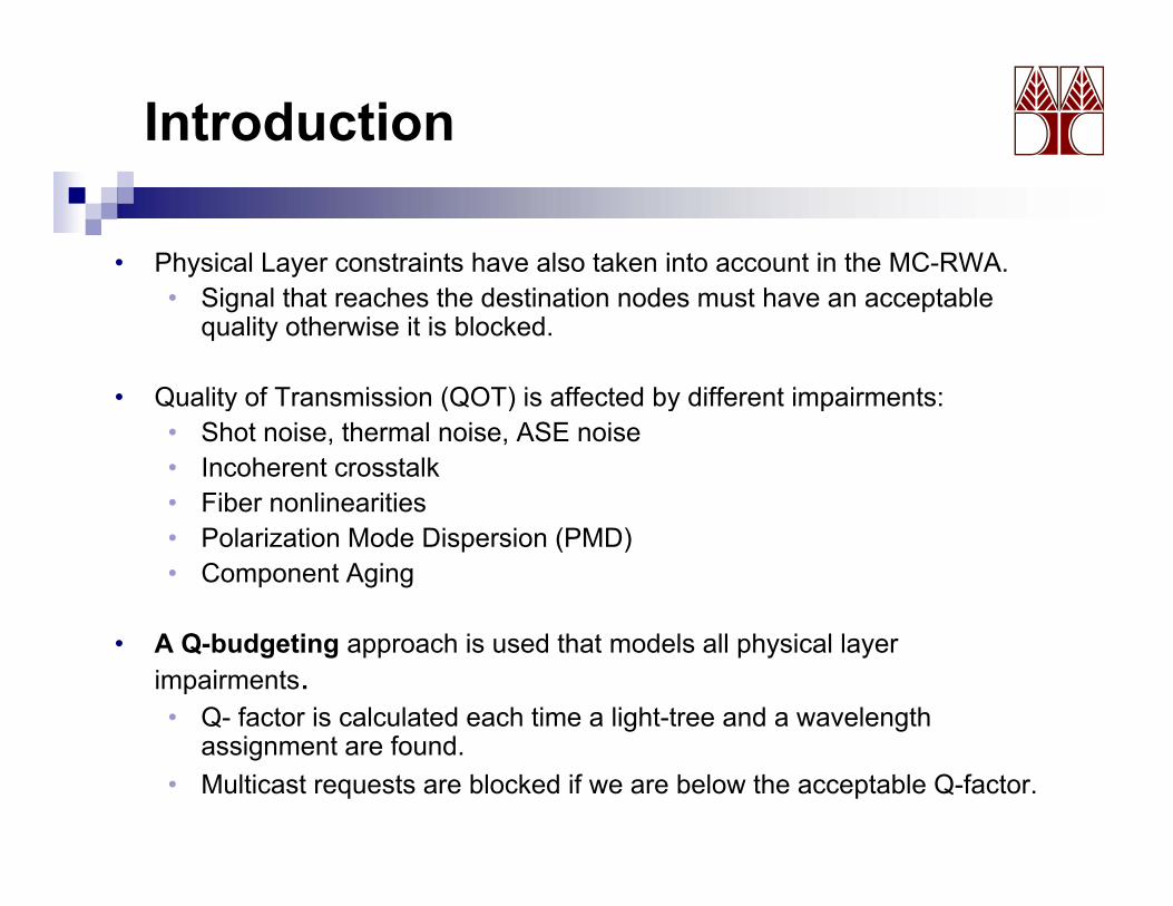
• Physical Layer constraints have also taken into account in the MC-RWA.• Signal that reaches the destination nodes must have an acceptable
quality otherwise it is blocked.
• Quality of Transmission (QOT) is affected by different impairments:• Quality of Transmission (QOT) is affected by different impairments:• Shot noise, thermal noise, ASE noise• Incoherent crosstalk • Fiber nonlinearitiesFiber nonlinearities• Polarization Mode Dispersion (PMD)• Component Aging
• A Q-budgeting approach is used that models all physical layer impairments.• Q- factor is calculated each time a light-tree and a wavelength
i t f dassignment are found.• Multicast requests are blocked if we are below the acceptable Q-factor.
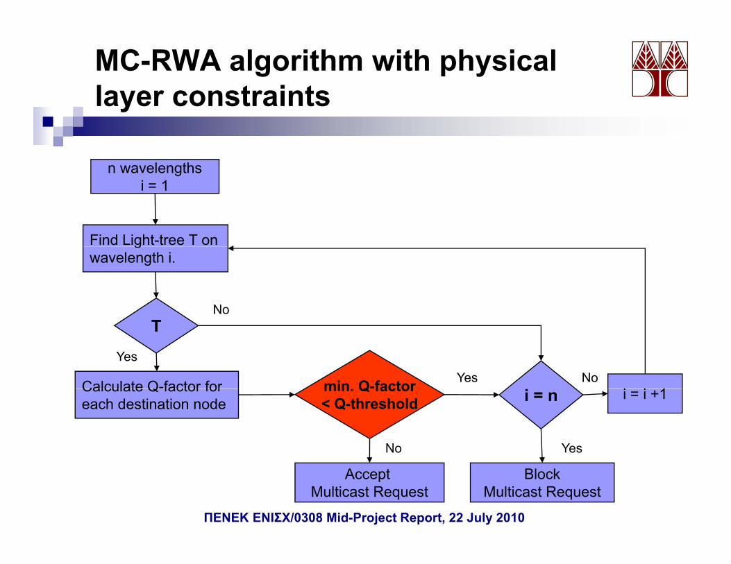
MC-RWA algorithm with physical layer constraintslayer constraints
n wavelengthsgi = 1
Find Light-tree T ongwavelength i.
NoT
Calculate Q-factor for min Q-factor i i 1
YesYes NoCalculate Q factor for
each destination nodemin. Q factor< Q-threshold i = n i = i +1
No Yes
Accept Multicast Request
BlockMulticast Request
ΠΕΝΕΚ ΕΝΙΣΧ/0308 Mid-Project Report, 22 July 2010

Q- budgeting model
• We are interested in the Bit Error Rate (BER).
• As the BER is a difficult parameter to evaluate, we can derive the required system Qfactor for a target BER using the following equation:
1 2QerfcBER eQ−
≈⎟⎞
⎜⎛
=
• The Q parameter for a system is calculated often in dBs so we use the following definition for QdB:
QdB 10log (Qlinear)
π222 QerfcBER ≈⎟
⎠⎜⎝
=
QdB = 10log (Qlinear)
• The value of the Q factor can be calculated using Equation:
01− IIQ
• where σi is the sum of the variances of the thermal noise, shot noise, various components of beat noise, and RIN noise.
σσ 01
01
+=Q
σσσσσσσ 2222222
shotASEiRINiASEsASEASEishotthi −−−−−−+++++=
ΠΕΝΕΚ ΕΝΙΣΧ/0308 Mid-Project Report, 22 July 2010
Q- budgeting model
• This approach assumes a baseline system with various receiver noise terms as well as ASE noise.noise terms as well as ASE noise.
• A Q-budgeting approach is used to include: • Incoherent crosstalk channel penalty budgeted at 0.8dBQ.• Fiber nonlinearities factored at 1 dBQ.• PMD budgeted at 0.2 dBQ.• Optical filter narrowing penalty budgeted at 0.4 dBQ.
S f t i f 1dBQ i l d d f t i• Safety margin of 1dBQ included for component aging. • No polarization-dependent gain/loss (PDG/PDL) are present.
• This approach enables a network designer to calculate the impact ofphysical layer effects, such as non-linear effects, polarization effects,optical crosstalk, etc, in the design of an optical network.
ΠΕΝΕΚ ΕΝΙΣΧ/0308 Mid-Project Report, 22 July 2010
Multicast Routing Algorithms
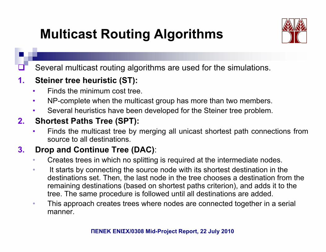
Several multicast routing algorithms are used for the simulations.1 St i t h i ti (ST)1. Steiner tree heuristic (ST):
• Finds the minimum cost tree.• NP-complete when the multicast group has more than two members.• Several heuristics have been developed for the Steiner tree problem• Several heuristics have been developed for the Steiner tree problem.
2. Shortest Paths Tree (SPT):• Finds the multicast tree by merging all unicast shortest path connections from
source to all destinations.3. Drop and Continue Tree (DAC):
• Creates trees in which no splitting is required at the intermediate nodes.• It starts by connecting the source node with its shortest destination in the y g
destinations set. Then, the last node in the tree chooses a destination from the remaining destinations (based on shortest paths criterion), and adds it to the tree. The same procedure is followed until all destinations are added.
• This approach creates trees where nodes are connected together in a serialThis approach creates trees where nodes are connected together in a serial manner.
ΠΕΝΕΚ ΕΝΙΣΧ/0308 Mid-Project Report, 22 July 2010
Multicast Routing Algorithms
4. Minimum Hop Tree (MHT):• Finds the minimum hop tree • Steiner tree heuristic with equal weights assigned to the links of the
network.
5. Balanced Light-Tree (BLT):• Balancing procedure that takes power budget constraints into
considerationconsideration.• Aims at minimizing the average splitting losses of the tree.
6 Max Degree Tree (MDT F):6. Max Degree Tree (MDT_F):• It takes into account only the power budget.• Controls splitting losses at the nodes by not allowing the construction
of trees with node degree greater than a predetermined value F.g g p
ΠΕΝΕΚ ΕΝΙΣΧ/0308 Mid-Project Report, 22 July 2010
Multicast Routing Algorithms
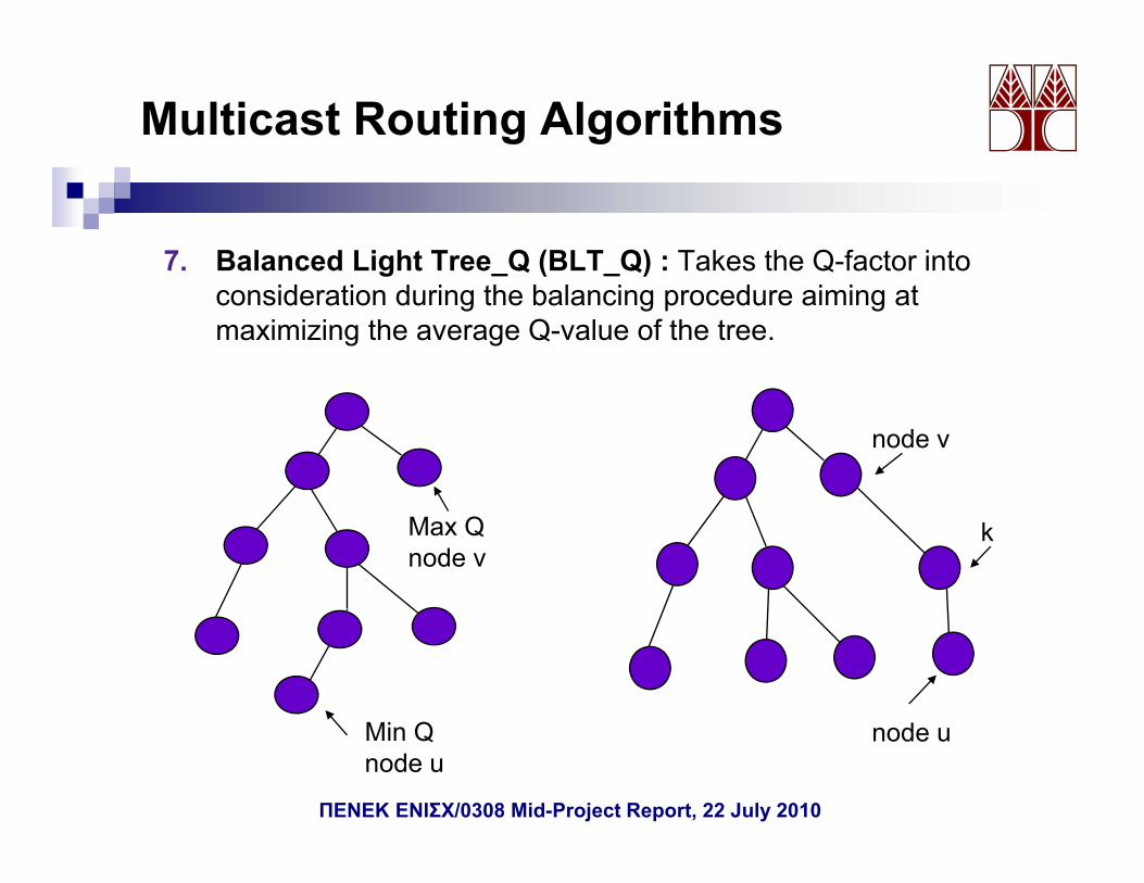
7. Balanced Light Tree_Q (BLT_Q) : Takes the Q-factor into g _ ( _ )consideration during the balancing procedure aiming at maximizing the average Q-value of the tree.
node v
Max Q node v
k
Min Qnode u
node u
ΠΕΝΕΚ ΕΝΙΣΧ/0308 Mid-Project Report, 22 July 2010
Multicast Routing Algorithms
• The balancing part of the algorithm terminates when two successive iterations fail to increase the minimum Q-factor.
• Tends to create shallower trees increasing the Q-value at the destination nodes and increasing the total number of the links in the treetree.
8. Balanced Light tree_Qtolerance (BLT_Qtolerance):BLT Q l ith i difi d t BLT Qt l t i i th• BLT Q algorithm is modified to BLT_Qtolerance to maximize the average Q-value of the tree and at the same time to keep the total number of the links in the tree as low as possible.
• Considering that the tolerance Q-factor is q this algorithm maximizes• Considering that the tolerance Q-factor is q, this algorithm maximizes the Q-factor only at those destination nodes that the Q-factor is below q.
• Terminates if the Q-value of all destination nodes in the tree is above q, or if two successive iterations fail to increase the minimum Q-factor.
ΠΕΝΕΚ ΕΝΙΣΧ/0308 Mid-Project Report, 22 July 2010
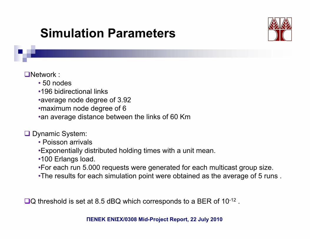
Simulation Parameters
Network :Network :• 50 nodes•196 bidirectional links•average node degree of 3.92•maximum node degree of 6•an average distance between the links of 60 Km
Dynamic System:Dynamic System:• Poisson arrivals•Exponentially distributed holding times with a unit mean.•100 Erlangs load.F h 000 d f h l i i•For each run 5.000 requests were generated for each multicast group size.
•The results for each simulation point were obtained as the average of 5 runs .
Q threshold is set at 8.5 dBQ which corresponds to a BER of 10-12 .
ΠΕΝΕΚ ΕΝΙΣΧ/0308 Mid-Project Report, 22 July 2010
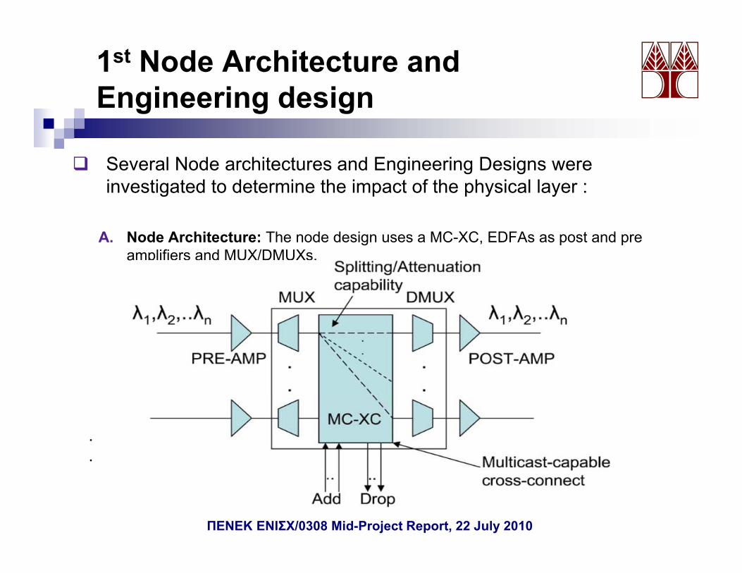
1st Node Architecture and Engineering designEngineering design
Several Node architectures and Engineering Designs were investigated to determine the impact of the physical layer :
A. Node Architecture: The node design uses a MC-XC, EDFAs as post and pre lifi d MUX/DMUXamplifiers and MUX/DMUXs.
.
...
ΠΕΝΕΚ ΕΝΙΣΧ/0308 Mid-Project Report, 22 July 2010
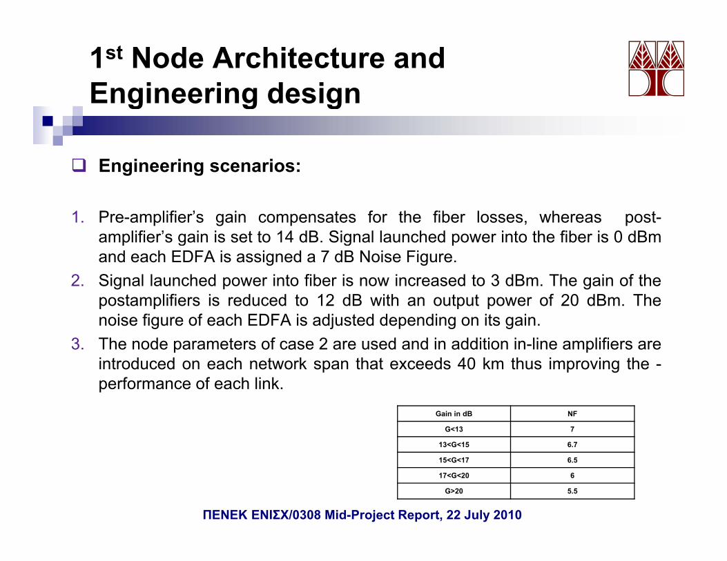
1st Node Architecture and Engineering designg g g
Engineering scenarios: g g
1. Pre-amplifier’s gain compensates for the fiber losses, whereas post-amplifier’s gain is set to 14 dB. Signal launched power into the fiber is 0 dBmp g g pand each EDFA is assigned a 7 dB Noise Figure.
2. Signal launched power into fiber is now increased to 3 dBm. The gain of thepostamplifiers is reduced to 12 dB with an output power of 20 dBm. The
i fi f h EDFA i dj t d d di it inoise figure of each EDFA is adjusted depending on its gain.3. The node parameters of case 2 are used and in addition in-line amplifiers are
introduced on each network span that exceeds 40 km thus improving the -performance of each linkperformance of each link.
Gain in dB NF
G<13 7
13<G<15 6.7
15 G 17 6 515<G<17 6.5
17<G<20 6
G>20 5.5
ΠΕΝΕΚ ΕΝΙΣΧ/0308 Mid-Project Report, 22 July 2010
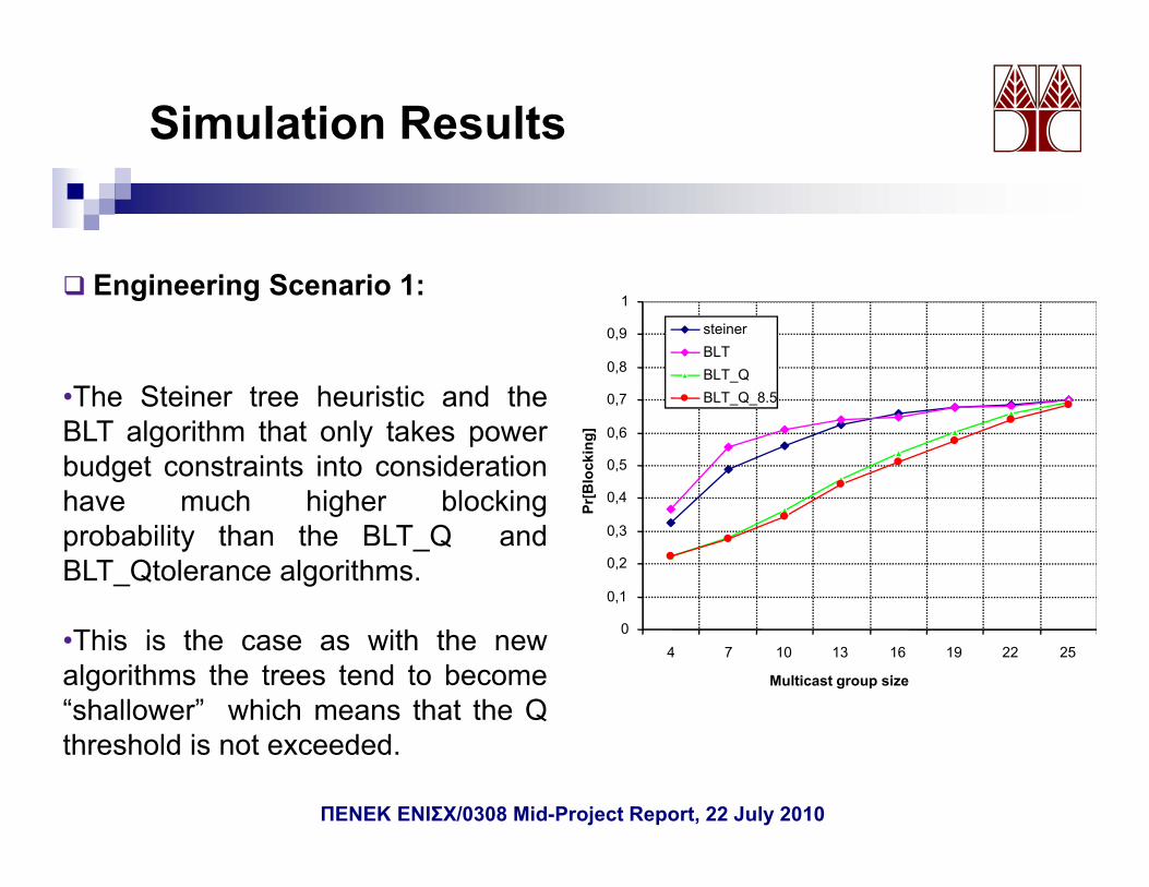
Simulation Results
E i i S i 1
0,8
0,9
1
steinerBLTBLT_Q
Engineering Scenario 1:
Th St i t h i ti d th
0 4
0,5
0,6
0,7
r[B
lock
ing]
BLT_Q_8.5•The Steiner tree heuristic and theBLT algorithm that only takes powerbudget constraints into considerationhave much higher blocking
0,1
0,2
0,3
0,4
Prhave much higher blockingprobability than the BLT_Q andBLT_Qtolerance algorithms.
04 7 10 13 16 19 22 25
Multicast group size
•This is the case as with the newalgorithms the trees tend to become“shallower” which means that the Qthreshold is not exceeded.
ΠΕΝΕΚ ΕΝΙΣΧ/0308 Mid-Project Report, 22 July 2010
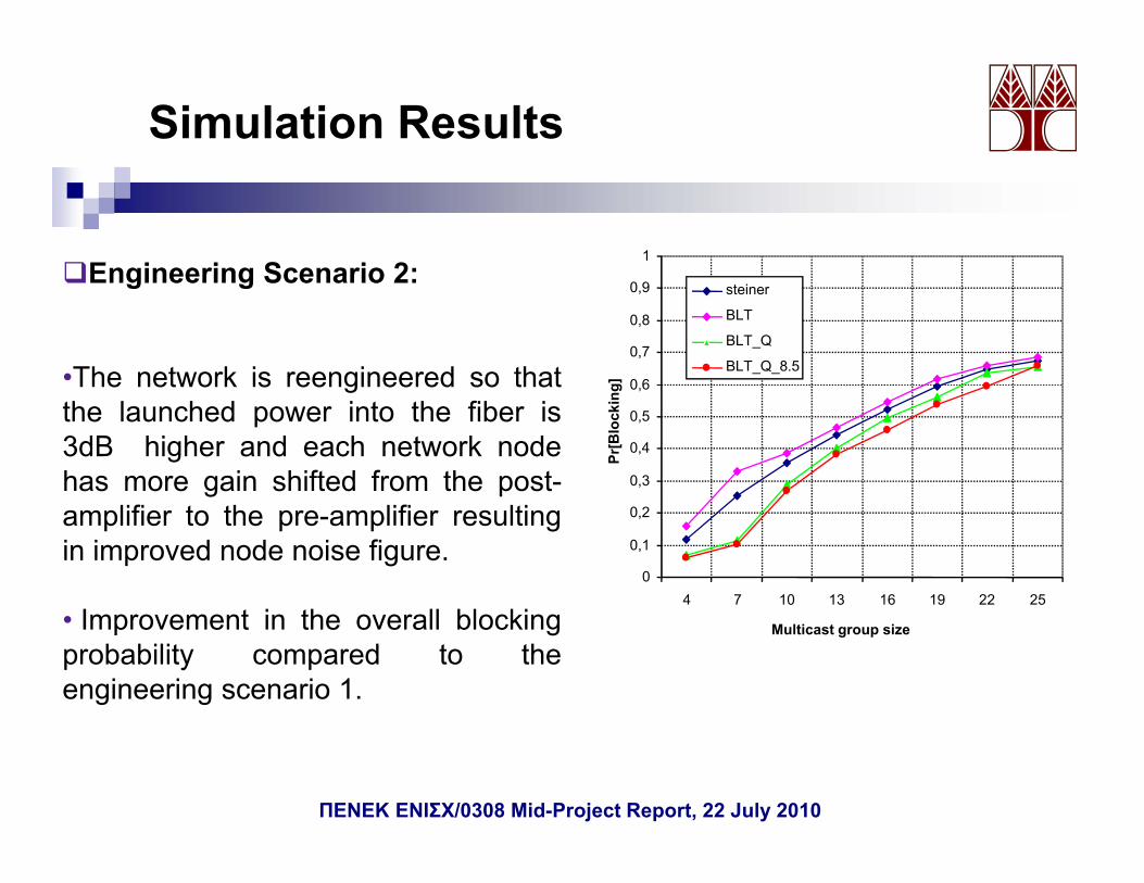
Simulation Results
1Engineering Scenario 2:
0 6
0,7
0,8
0,9
g]
steiner
BLT
BLT_Q
BLT_Q_8.5
Engineering Scenario 2:
•The network is reengineered so that
0,3
0,4
0,5
0,6
Pr[B
lock
ingThe network is reengineered so that
the launched power into the fiber is3dB higher and each network nodehas more gain shifted from the post-
0
0,1
0,2
4 7 10 13 16 19 22 25
amplifier to the pre-amplifier resultingin improved node noise figure.
Multicast group size• Improvement in the overall blockingprobability compared to theengineering scenario 1.
ΠΕΝΕΚ ΕΝΙΣΧ/0308 Mid-Project Report, 22 July 2010
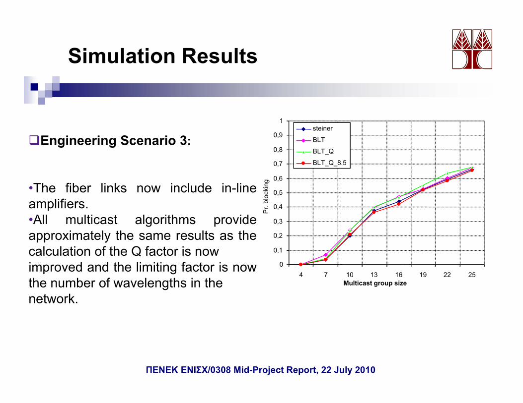
Simulation Results
1
0 6
0,7
0,8
0,9steiner
BLT
BLT_Q
BLT_Q_8.5
Engineering Scenario 3:
0,3
0,4
0,5
0,6
Pr.
bloc
king•The fiber links now include in-line
amplifiers.•All multicast algorithms provide
0
0,1
0,2
4 7 10 13 16 19 22 25
approximately the same results as thecalculation of the Q factor is nowimproved and the limiting factor is now
f Multicast group sizethe number of wavelengths in thenetwork.
ΠΕΝΕΚ ΕΝΙΣΧ/0308 Mid-Project Report, 22 July 2010
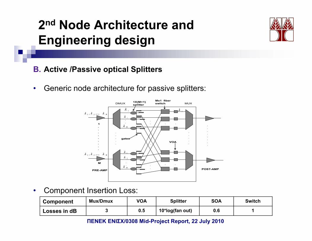
2nd Node Architecture and Engineering designg g g
B. Active /Passive optical Splitters
• Generic node architecture for passive splitters:Mx1 fiber switch1X(M+1)
splitterDMUX MUX splitter
Nλλλ ,...,, 21
1λ
Nλ
2λ
1....
.
.
.
...
.
.
.
.
.
. . .
1λ
Nλλλ ,...,, 211λ
λ
2λ
.
.
.
.
.
.
M
gatesVOA
.
.
.
.
.
.
.
.
.
.
.
.
...
. . .
• Component Insertion Loss:
POST-AMPPRE-AMPNλ .
Component Mux/Dmux VOA Splitter SOA Switch
Losses in dB 3 0.5 10*log(fan out) 0.6 1
ΠΕΝΕΚ ΕΝΙΣΧ/0308 Mid-Project Report, 22 July 2010
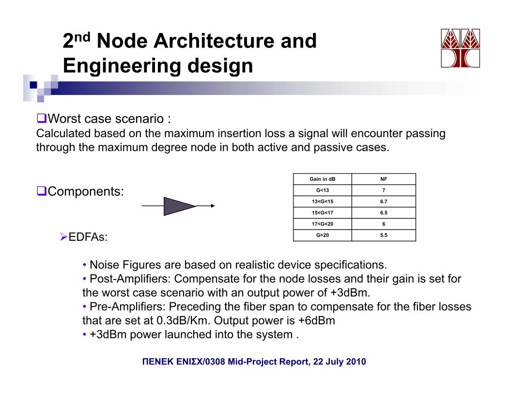
2nd Node Architecture and Engineering designg g g
Worst case scenario :Worst case scenario :Calculated based on the maximum insertion loss a signal will encounter passing through the maximum degree node in both active and passive cases.
Components:Gain in dB NF
G<13 7
13<G<15 6.7
15<G<17 6.5
G
EDFAs:
• Noise Figures are based on realistic device specifications.
17<G<20 6
G>20 5.5
• Post-Amplifiers: Compensate for the node losses and their gain is set for the worst case scenario with an output power of +3dBm.• Pre-Amplifiers: Preceding the fiber span to compensate for the fiber losses that are set at 0 3dB/Km Output power is +6dBmthat are set at 0.3dB/Km. Output power is +6dBm• +3dBm power launched into the system .
ΠΕΝΕΚ ΕΝΙΣΧ/0308 Mid-Project Report, 22 July 2010
2nd Node Architecture and Engineering designg g g
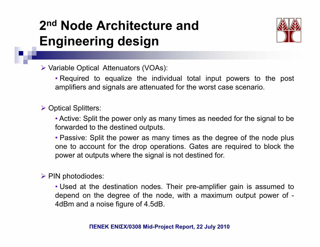
Variable Optical Attenuators (VOAs):R i d t li th i di id l t t l i t t th t• Required to equalize the individual total input powers to the post
amplifiers and signals are attenuated for the worst case scenario.
Optical Splitters:Optical Splitters:• Active: Split the power only as many times as needed for the signal to beforwarded to the destined outputs.• Passive: Split the power as many times as the degree of the node plusPassive: Split the power as many times as the degree of the node plusone to account for the drop operations. Gates are required to block thepower at outputs where the signal is not destined for.
PIN photodiodes:• Used at the destination nodes. Their pre-amplifier gain is assumed todepend on the degree of the node, with a maximum output power of -4dB d i fi f 4 5dB4dBm and a noise figure of 4.5dB.
ΠΕΝΕΚ ΕΝΙΣΧ/0308 Mid-Project Report, 22 July 2010
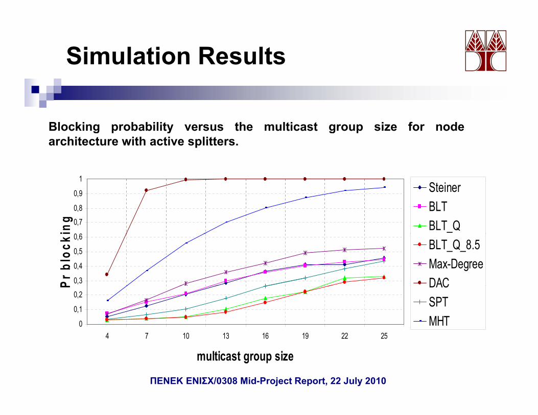
Simulation Results
Blocking probability versus the multicast group size for node
1
Blocking probability versus the multicast group size for nodearchitecture with active splitters.
0 6
0,7
0,8
0,9
1
ing
SteinerBLTBLT_Q
0,3
0,4
0,5
0,6
Pr b
lock
i
BLT_Q_8.5Max-DegreeDAC
0
0,1
0,2
4 7 10 13 16 19 22 25
P DACSPTMHT
4 7 10 13 16 19 22 25
multicast group size
ΠΕΝΕΚ ΕΝΙΣΧ/0308 Mid-Project Report, 22 July 2010
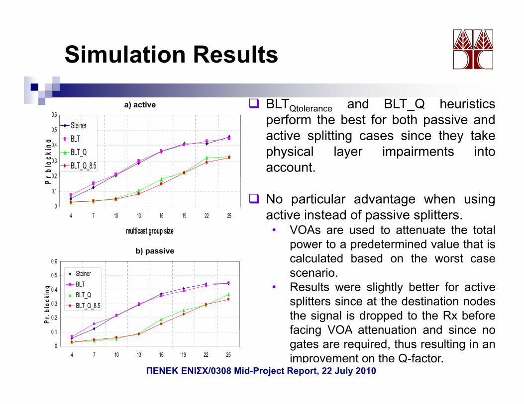
Simulation Results
BLTQtolerance and BLT_Q heuristicsperform the best for both passive and0,6
Steiner
a) active
p pactive splitting cases since they takephysical layer impairments intoaccount.
0 2
0,3
0,4
0,5
r blo
ckin
g
SteinerBLTBLT_QBLT_Q_8.5
No particular advantage when usingactive instead of passive splitters.
VOAs are sed to atten ate the total
0
0,1
0,2
4 7 10 13 16 19 22 25
lti t i
Pr
• VOAs are used to attenuate the totalpower to a predetermined value that iscalculated based on the worst casescenario.
multicast group size
0,5
0,6
Steiner
b) passive
• Results were slightly better for activesplitters since at the destination nodesthe signal is dropped to the Rx beforefacing VOA attenuation and since no
0,2
0,3
0,4
Pr. b
lock
ing BLT
BLT_QBLT_Q_8.5
facing VOA attenuation and since nogates are required, thus resulting in animprovement on the Q-factor.
0
0,1
4 7 10 13 16 19 22 25
multicast group sizeΠΕΝΕΚ ΕΝΙΣΧ/0308 Mid-Project Report, 22 July 2010
3rd Node Architecture and Engineering designg g g
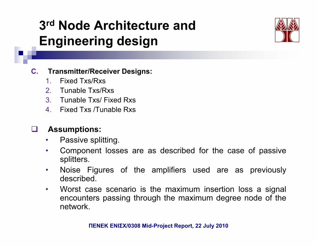
C. Transmitter/Receiver Designs: 1. Fixed Txs/Rxs2. Tunable Txs/Rxs 3. Tunable Txs/ Fixed Rxs4 Fi d T /T bl R4. Fixed Txs /Tunable Rxs
Assumptions:Passive splitting• Passive splitting.
• Component losses are as described for the case of passivesplitters.
• Noise Figures of the amplifiers used are as previously• Noise Figures of the amplifiers used are as previouslydescribed.
• Worst case scenario is the maximum insertion loss a signalencounters passing through the maximum degree node of thep g g gnetwork.
ΠΕΝΕΚ ΕΝΙΣΧ/0308 Mid-Project Report, 22 July 2010
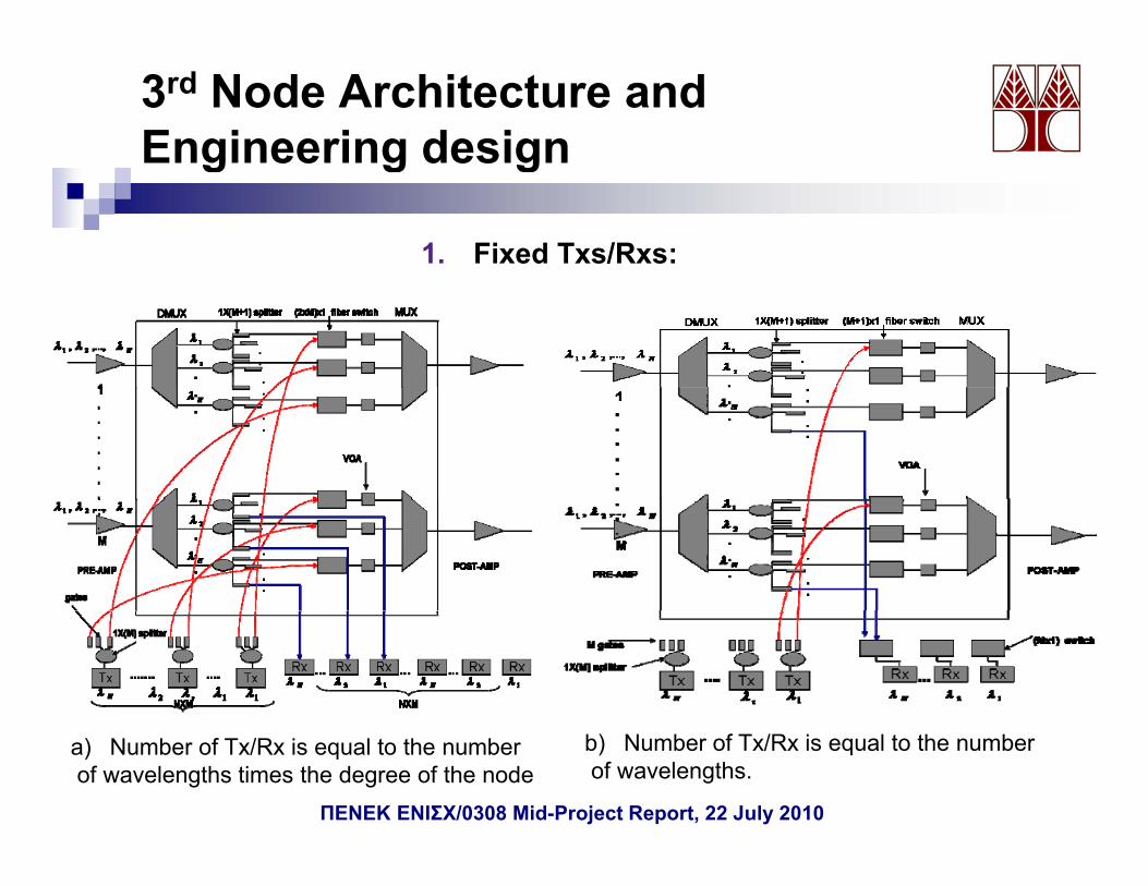
3rd Node Architecture and Engineering design
1. Fixed Txs/Rxs:
g g g
a) Number of Tx/Rx is equal to the numberof wavelengths times the degree of the node
b) Number of Tx/Rx is equal to the numberof wavelengths.
ΠΕΝΕΚ ΕΝΙΣΧ/0308 Mid-Project Report, 22 July 2010
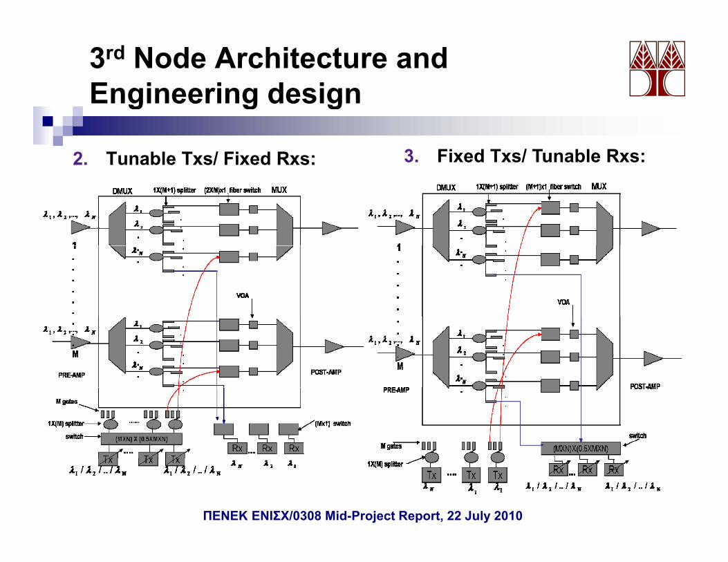
3rd Node Architecture and Engineering design
2. Tunable Txs/ Fixed Rxs:
g g g
3. Fixed Txs/ Tunable Rxs:
ΠΕΝΕΚ ΕΝΙΣΧ/0308 Mid-Project Report, 22 July 2010
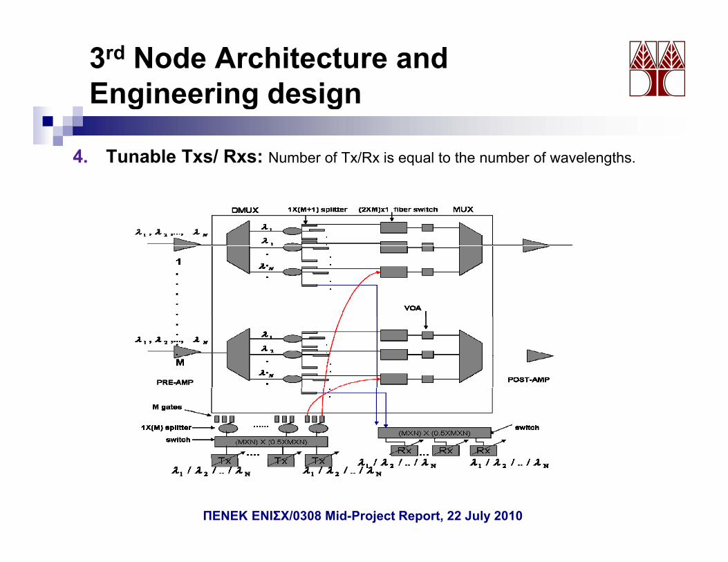
3rd Node Architecture and Engineering designg g g
4. Tunable Txs/ Rxs: Number of Tx/Rx is equal to the number of wavelengths.
ΠΕΝΕΚ ΕΝΙΣΧ/0308 Mid-Project Report, 22 July 2010
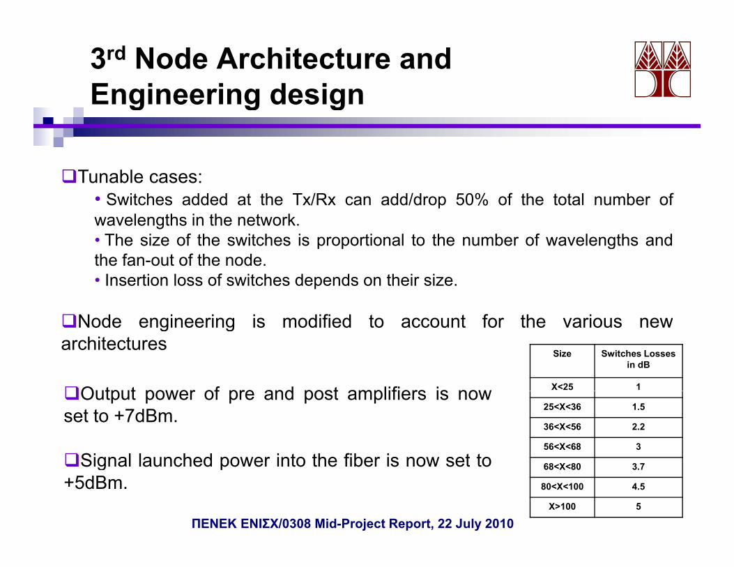
3rd Node Architecture and Engineering designg g g
Tunable cases:Tunable cases:• Switches added at the Tx/Rx can add/drop 50% of the total number ofwavelengths in the network.• The size of the switches is proportional to the number of wavelengths andp p gthe fan-out of the node.• Insertion loss of switches depends on their size.
Node engineering is modified to account for the various newNode engineering is modified to account for the various newarchitectures
Size Switches Losses in dB
X<25 1Output power of pre and post amplifiers is now25<X<36 1.5
36<X<56 2.2
56<X<68 3
Output power of pre and post amplifiers is nowset to +7dBm.
Signal launched power into the fiber is now set to 68<X<80 3.7
80<X<100 4.5
X>100 5
Signal launched power into the fiber is now set to+5dBm.
ΠΕΝΕΚ ΕΝΙΣΧ/0308 Mid-Project Report, 22 July 2010
3rd Node Architecture and Engineering designg g g
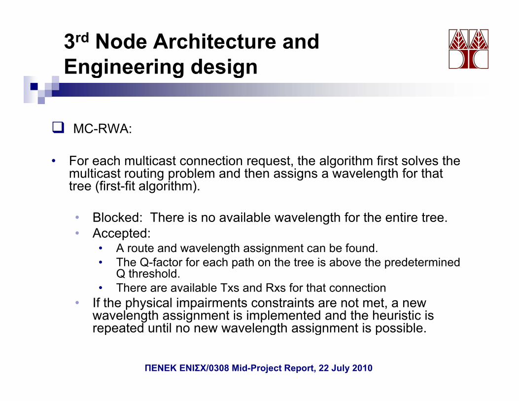
MC RWAMC-RWA:
• For each multicast connection request, the algorithm first solves the multicast routing problem and then assigns a wavelength for thatmulticast routing problem and then assigns a wavelength for that tree (first-fit algorithm).
• Blocked: There is no available wavelength for the entire tree.• Accepted:
• A route and wavelength assignment can be found.• The Q-factor for each path on the tree is above the predetermined
Q threshold.Q threshold.• There are available Txs and Rxs for that connection
• If the physical impairments constraints are not met, a new wavelength assignment is implemented and the heuristic is repeated until no new wavelength assignment is possiblerepeated until no new wavelength assignment is possible.
ΠΕΝΕΚ ΕΝΙΣΧ/0308 Mid-Project Report, 22 July 2010
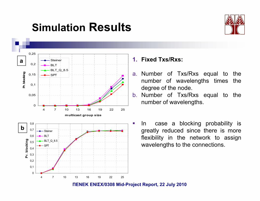
Simulation Results
0,25
Steinera 1. Fixed Txs/Rxs:
0,1
0,15
0,2
Pr. b
lock
ing
BLT
BLT_Q_8.5
SPT
a
a. Number of Txs/Rxs equal to thenumber of wavelengths times thedegree of the node
0
0,05
4 7 10 13 16 19 22 25
P degree of the node.b. Number of Txs/Rxs equal to the
number of wavelengths.
multicast group size
0,6
0,7
0,8
Steiner
BLT
bIn case a blocking probability isgreatly reduced since there is moreflexibility in the network to assign
0,2
0,3
0,4
0,5
Pr.
blo
ckin
g BLT_Q_8.5
SPT
flexibility in the network to assignwavelengths to the connections.
0
0,1
4 7 10 13 16 19 22 25
multicast group sizeΠΕΝΕΚ ΕΝΙΣΧ/0308 Mid-Project Report, 22 July 2010
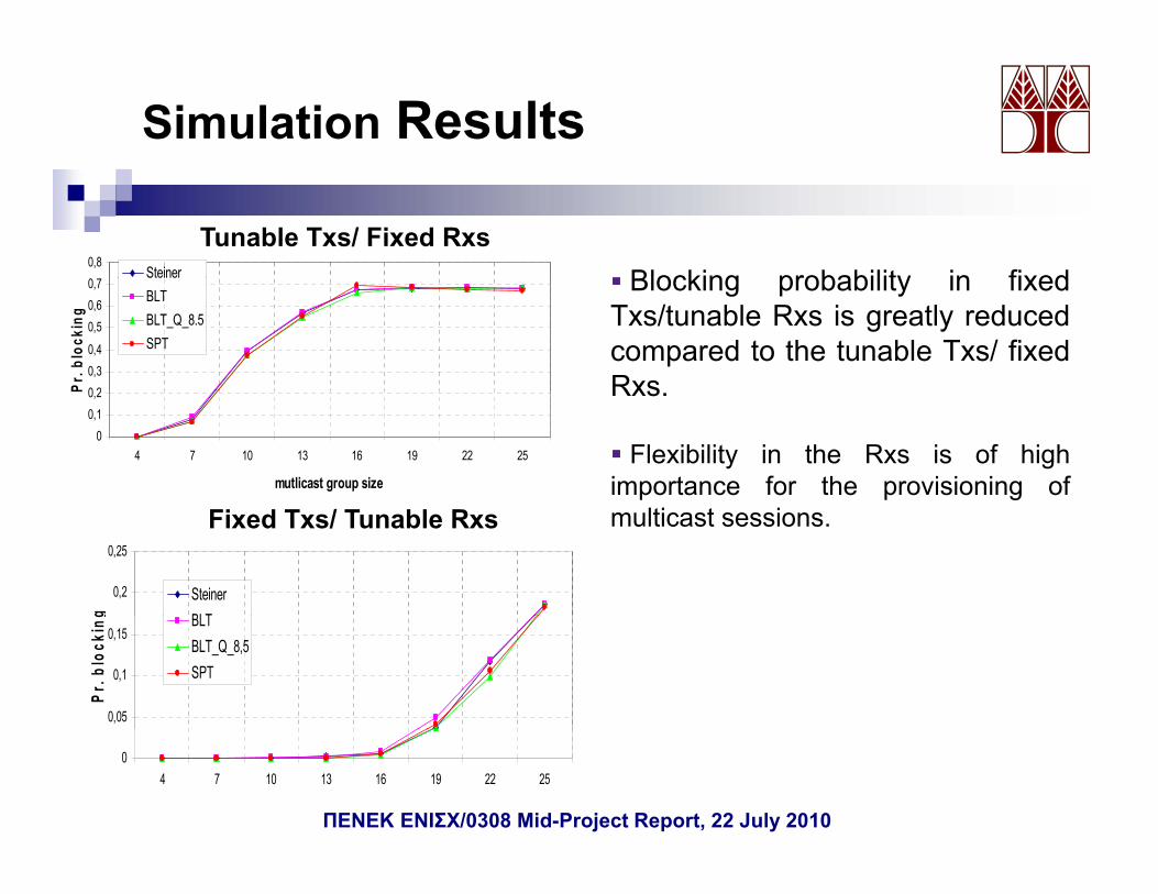
Simulation Results
0,8Steiner
Tunable Txs/ Fixed RxsBlocking probability in fixed
0 20,30,4
0,50,60,7
Pr. b
lock
ing
BLTBLT_Q_8.5SPT
Blocking probability in fixedTxs/tunable Rxs is greatly reducedcompared to the tunable Txs/ fixedRxs
00,10,2
4 7 10 13 16 19 22 25
mutlicast group size
P Rxs.
Flexibility in the Rxs is of highimportance for the provisioning of
0,2
0,25
g
SteinerBLT
Fixed Txs/ Tunable Rxs multicast sessions.
0,05
0,1
0,15
Pr. b
lock
ing BLT
BLT_Q_8,5SPT
04 7 10 13 16 19 22 25
multicast group sizeΠΕΝΕΚ ΕΝΙΣΧ/0308 Mid-Project Report, 22 July 2010
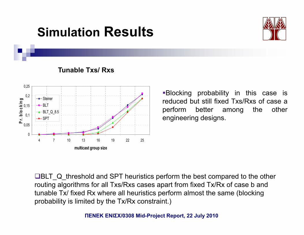
Simulation Results
Tunable Txs/ Rxs
0,2
0,25
ng SteinerBlocking probability in this case is
reduced but still fixed Txs/Rxs of case a
0,05
0,1
0,15
Pr. b
lock
in BLTBLT_Q_8.5SPT
reduced but still fixed Txs/Rxs of case aperform better among the otherengineering designs.
04 7 10 13 16 19 22 25
multicast group size
BLT_Q_threshold and SPT heuristics perform the best compared to the otherrouting algorithms for all Txs/Rxs cases apart from fixed Tx/Rx of case b andt nable T / fi ed R here all he ristics perform almost the same (blockingtunable Tx/ fixed Rx where all heuristics perform almost the same (blockingprobability is limited by the Tx/Rx constraint.)
ΠΕΝΕΚ ΕΝΙΣΧ/0308 Mid-Project Report, 22 July 2010
Work Package 4RWA for protected MC connections with PLCs (5-month duration)duration)
Development of a simulation code that performs therouting/protection and wavelength assignment under physical layerconstraints.
Development of novel protection techniques for multicast connections takingDevelopment of novel protection techniques for multicast connections taking into account the physical layer constraints:
LEVEL protection heuristicPCH protection heuristicQ Based PCH protection heuristic
And compared with existing protection techniquesMCH heuristicMC-CR heuristicMC-CR heuristicSegment Protection HeuristicSSNF heuristic
Self Sharing and Cross Sharing approaches were considered.
ΠΕΝΕΚ ΕΝΙΣΧ/0308 Mid-Project Report, 22 July 2010
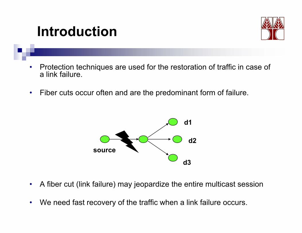
Introduction
• Protection techniques are used for the restoration of traffic in case of li k f ila link failure.
• Fiber cuts occur often and are the predominant form of failure.
d1
sourced2
d3
• A fiber cut (link failure) may jeopardize the entire multicast session
d3
• We need fast recovery of the traffic when a link failure occurs.
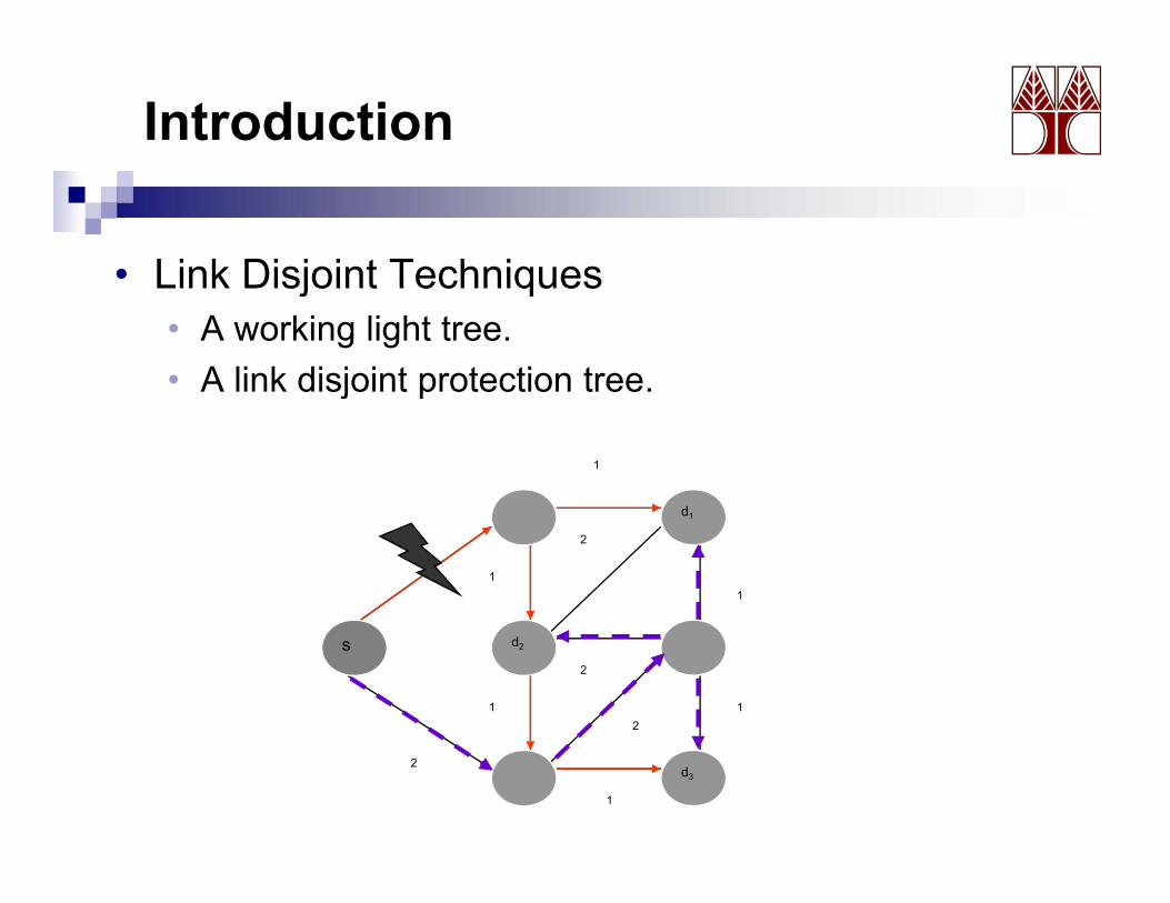
Introduction
• Link Disjoint TechniquesLink Disjoint Techniques• A working light tree.• A link disjoint protection tree.j p
d
1
d
1
d1
1
11
2
d1
1
1
s d2
1 12
2
s d2
1
d32
1
d3
1
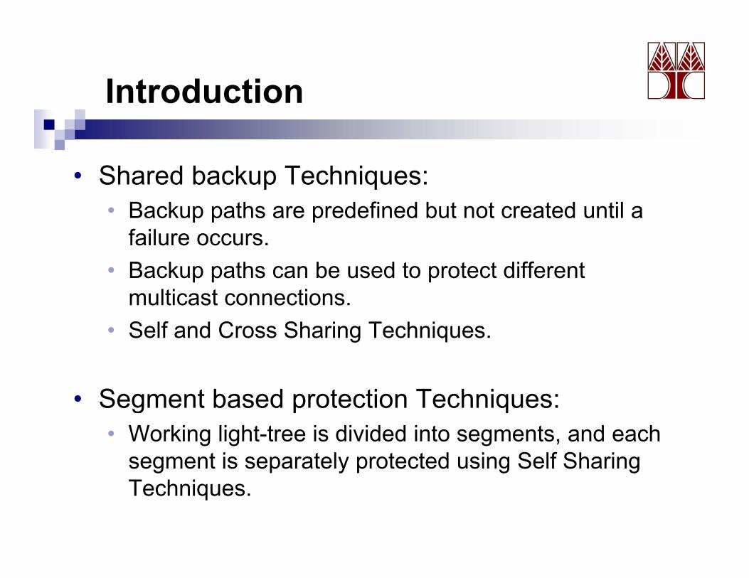
Introduction
• Shared backup Techniques:Shared backup Techniques:• Backup paths are predefined but not created until a
failure occurs.• Backup paths can be used to protect different
multicast connections. S lf d C Sh i T h i• Self and Cross Sharing Techniques.
• Segment based protection Techniques:• Segment based protection Techniques:• Working light-tree is divided into segments, and each
segment is separately protected using Self Sharing g p y p g gTechniques.
Introduction
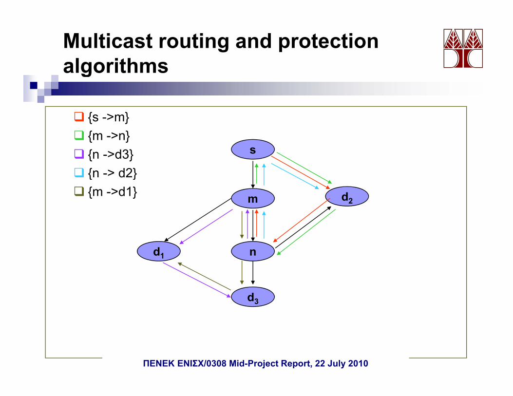
• {s ->m}{s m}• {m ->n}• {n ->d3}
s
• {n -> d2}• {m ->d1}
m d2
nd1
d3
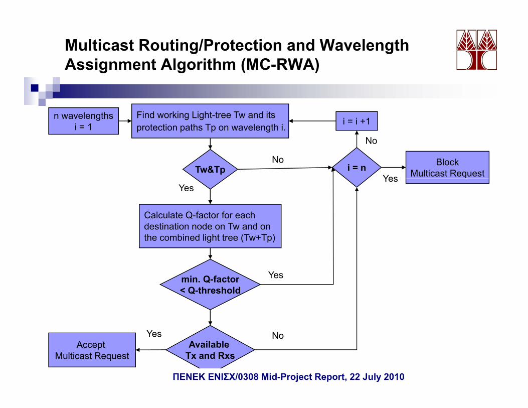
Multicast Routing/Protection and Wavelength Assignment Algorithm (MC-RWA)
n wavelengthsi = 1
Find working Light-tree Tw and itsprotection paths Tp on wavelength i i = i +1i = 1 protection paths Tp on wavelength i.
Tw&Tp i = n BlockMulticast RequestYes
No
No
Calculate Q-factor for eachdestination node on Tw and on
YesYes
the combined light tree (Tw+Tp)
min. Q-factor Yesmin. Q factor< Q-threshold
Yes NAccept
Multicast RequestAvailable
Tx and Rxs
Yes No
ΠΕΝΕΚ ΕΝΙΣΧ/0308 Mid-Project Report, 22 July 2010
Multicast routing and protection algorithms g
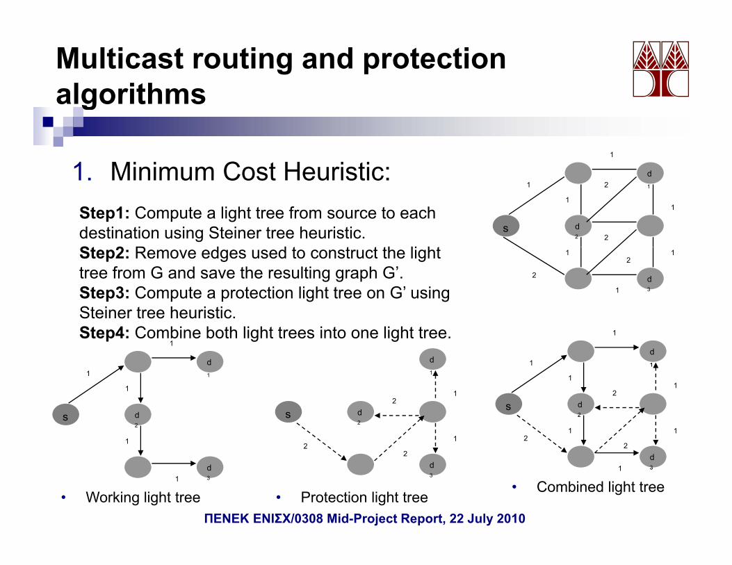
1 Minimum Cost Heuristic: d
1
1. Minimum Cost Heuristic:
s d2
d11
11
2
2
Step1: Compute a light tree from source to eachdestination using Steiner tree heuristic.St 2 R d d t t t th li ht
d3
2
1 1
1
2Step2: Remove edges used to construct the lighttree from G and save the resulting graph G’.Step3: Compute a protection light tree on G’ usingSteiner tree heuristic.
d11
1
1
d1
d1
1
d11
1
1
Ste e t ee eu st cStep4: Combine both light trees into one light tree.
s d2
1
1
s d2
1
12
2
2 s d2
d
12
2
2
s d2
d
1
d31
d3
• Working light tree • Protection light tree
331
• Combined light tree
ΠΕΝΕΚ ΕΝΙΣΧ/0308 Mid-Project Report, 22 July 2010
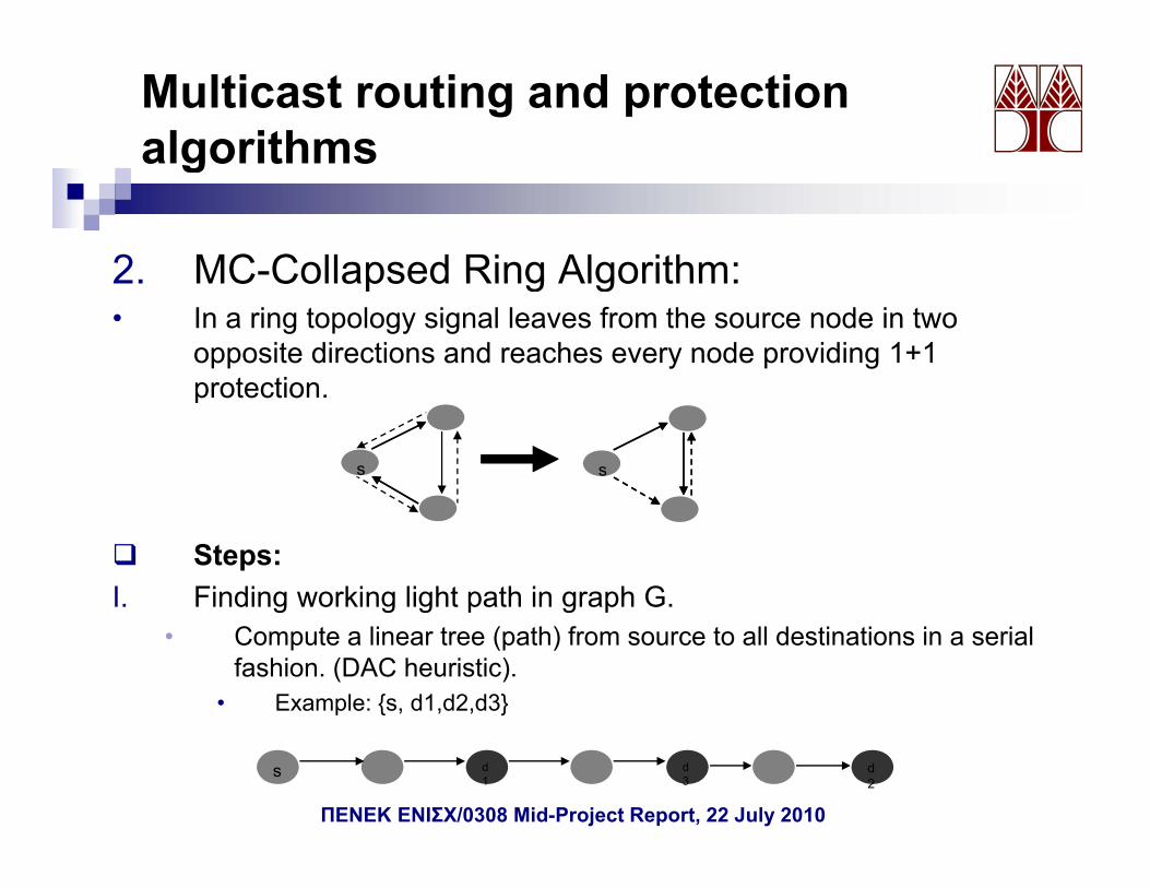
Multicast routing and protection algorithmsg
2 MC-Collapsed Ring Algorithm:2. MC Collapsed Ring Algorithm:• In a ring topology signal leaves from the source node in two
opposite directions and reaches every node providing 1+1 protectionprotection.
ss ss
Steps:I. Finding working light path in graph G.g g g p g p
• Compute a linear tree (path) from source to all destinations in a serial fashion. (DAC heuristic).
• Example: {s, d1,d2,d3}
d3
d1
s d2
ΠΕΝΕΚ ΕΝΙΣΧ/0308 Mid-Project Report, 22 July 2010
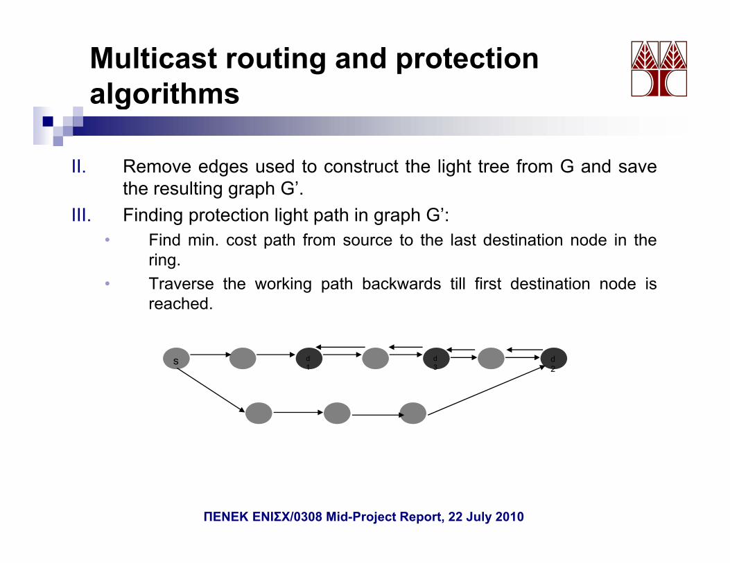
Multicast routing and protection algorithms
II. Remove edges used to construct the light tree from G and save
g
g gthe resulting graph G’.
III. Finding protection light path in graph G’:• Find min. cost path from source to the last destination node in thep
ring.• Traverse the working path backwards till first destination node is
reached.
d3
d1
s d2
ΠΕΝΕΚ ΕΝΙΣΧ/0308 Mid-Project Report, 22 July 2010
Multicast routing and protection algorithmsg
3 Level Protection Algorithm3. Level Protection Algorithm• Definitions:
I. Segment points: a vertex is said to be a segment point if itis the source or a desination node of the multicast request.
II. Segments: a path between two segmnet points is said tobe a segment.
III. Leveli of segment points: the level of a segment point isthe number of the segments between that segment pointand the source.
IV. Level(i-1,i) segment: is the set of all the segments of the tree that are between the segment points of level(i-1) and the segment points of leveli.
ΠΕΝΕΚ ΕΝΙΣΧ/0308 Mid-Project Report, 22 July 2010
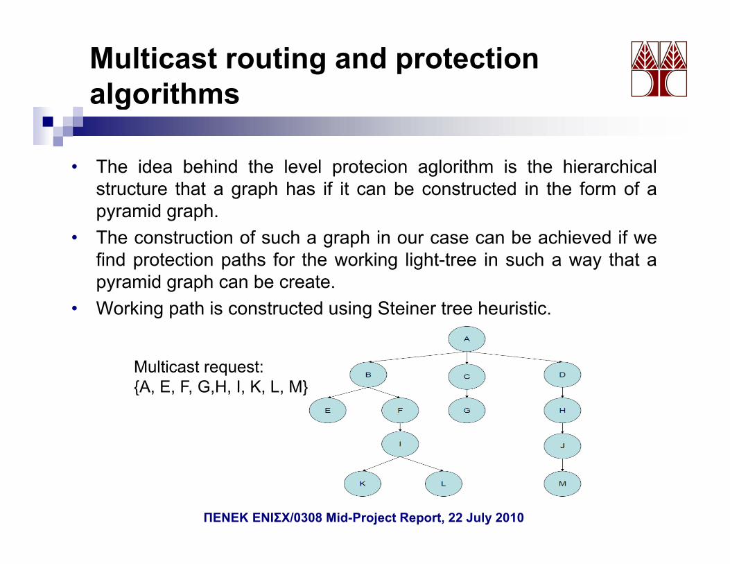
Multicast routing and protection algorithmsg
• The idea behind the level protecion aglorithm is the hierarchicalp gstructure that a graph has if it can be constructed in the form of apyramid graph.
• The construction of such a graph in our case can be achieved if weg pfind protection paths for the working light-tree in such a way that apyramid graph can be create.
• Working path is constructed using Steiner tree heuristic.g p g
Multicast request: {A E F G H I K L M}{A, E, F, G,H, I, K, L, M}
ΠΕΝΕΚ ΕΝΙΣΧ/0308 Mid-Project Report, 22 July 2010
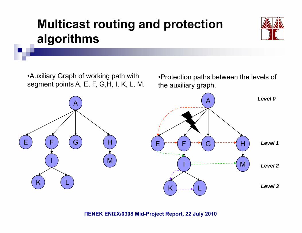
Multicast routing and protection algorithmsg
A
•Auxiliary Graph of working path with segment points A, E, F, G,H, I, K, L, M.
•Protection paths between the levels of the auxiliary graph.
A Level 0A A
I
FE G H
M
FE G H Level 1
LK
I M
LK
I M Level 2
Level 3LK
ΠΕΝΕΚ ΕΝΙΣΧ/0308 Mid-Project Report, 22 July 2010
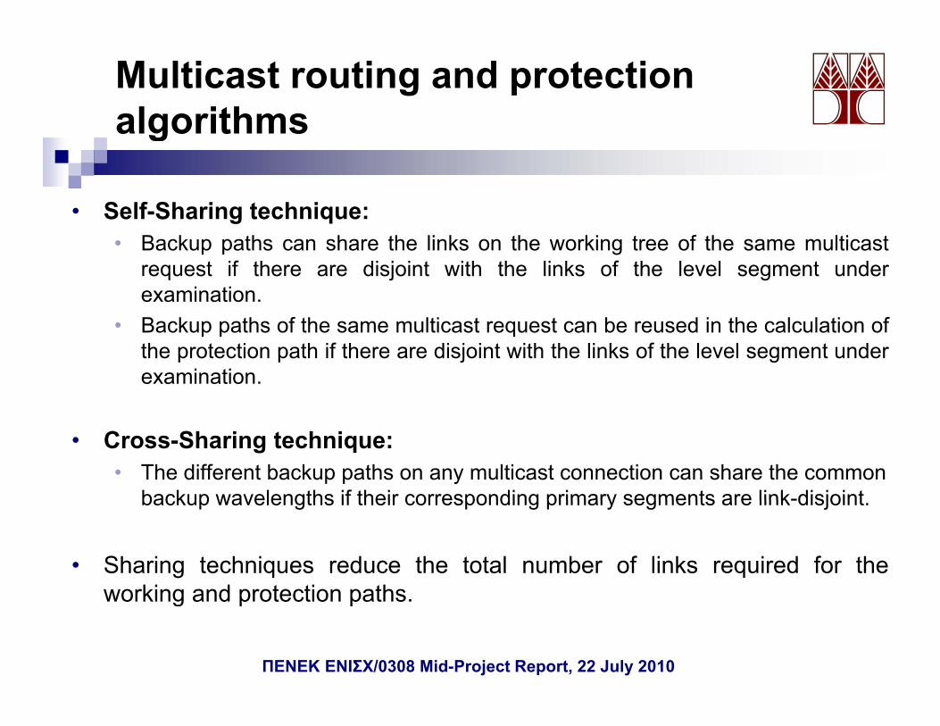
Multicast routing and protection algorithmsg
• Self-Sharing technique:• Backup paths can share the links on the working tree of the same multicast
request if there are disjoint with the links of the level segment underexamination.B k h f h l i b d i h l l i f• Backup paths of the same multicast request can be reused in the calculation ofthe protection path if there are disjoint with the links of the level segment underexamination.
• Cross-Sharing technique:• The different backup paths on any multicast connection can share the common
backup wavelengths if their corresponding primary segments are link-disjointbackup wavelengths if their corresponding primary segments are link-disjoint.
• Sharing techniques reduce the total number of links required for theworking and protection pathsworking and protection paths.
ΠΕΝΕΚ ΕΝΙΣΧ/0308 Mid-Project Report, 22 July 2010
Multicast routing and protection algorithmsg
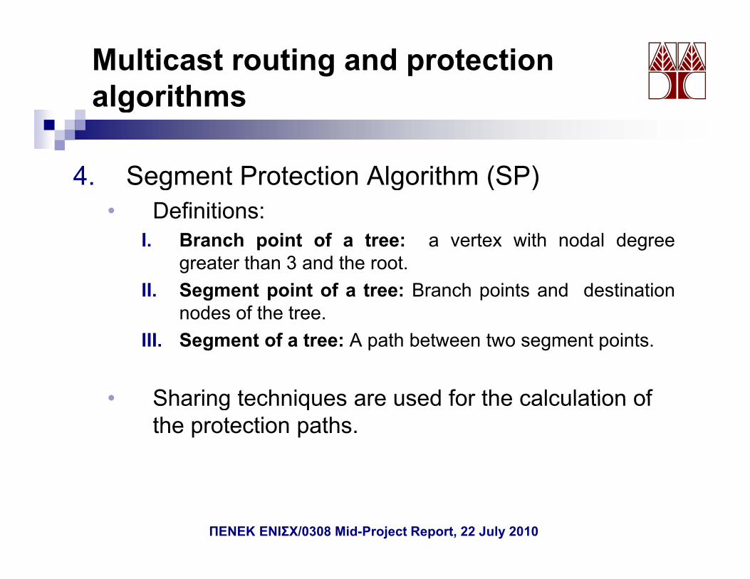
4 Segment Protection Algorithm (SP)4. Segment Protection Algorithm (SP)• Definitions:
I. Branch point of a tree: a vertex with nodal degreegreater than 3 and the root.
II. Segment point of a tree: Branch points and destinationnodes of the tree.
III. Segment of a tree: A path between two segment points.
• Sharing techniques are used for the calculation of• Sharing techniques are used for the calculation of the protection paths.
ΠΕΝΕΚ ΕΝΙΣΧ/0308 Mid-Project Report, 22 July 2010
Multicast routing and protection algorithmsg
• Working light-tree is calculated using Steiner tree heuristic
s
m d2
s
m dm
n
d2
d1
Working light tree m
n
d2
d1
Network topology
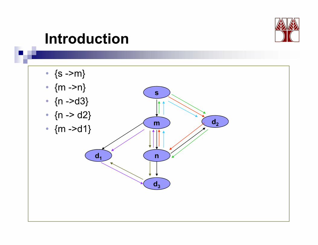
• Once the protection light tree is created, the branch points, segmenti t d th t id tifi d
d3 d3
points and the segments are identified.• Branch points: s, m, n• Segment points: s, m, n, d1, d2, d3• Segments: {s >m} {m >n} {n >d3} {n > d2} {m >d1}• Segments: {s ->m}, {m ->n}, {n ->d3}, {n -> d2}, {m ->d1}
• Auxiliary graph is created.
ΠΕΝΕΚ ΕΝΙΣΧ/0308 Mid-Project Report, 22 July 2010
Multicast routing and protection algorithmsg
{s ->m}{ }{m ->n}{n ->d3}{n > d2}
s
{n -> d2}{m ->d1} m d2
nd1
d3
ΠΕΝΕΚ ΕΝΙΣΧ/0308 Mid-Project Report, 22 July 2010
Multicast routing and protection algorithmsg
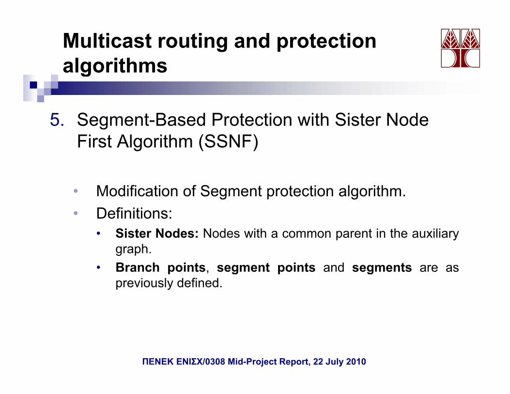
5 Segment-Based Protection with Sister Node5. Segment Based Protection with Sister Node First Algorithm (SSNF)
• Modification of Segment protection algorithm.• Definitions:
• Sister Nodes: Nodes with a common parent in the auxiliarygraph.
• Branch points, segment points and segments are asBranch points, segment points and segments are aspreviously defined.
ΠΕΝΕΚ ΕΝΙΣΧ/0308 Mid-Project Report, 22 July 2010
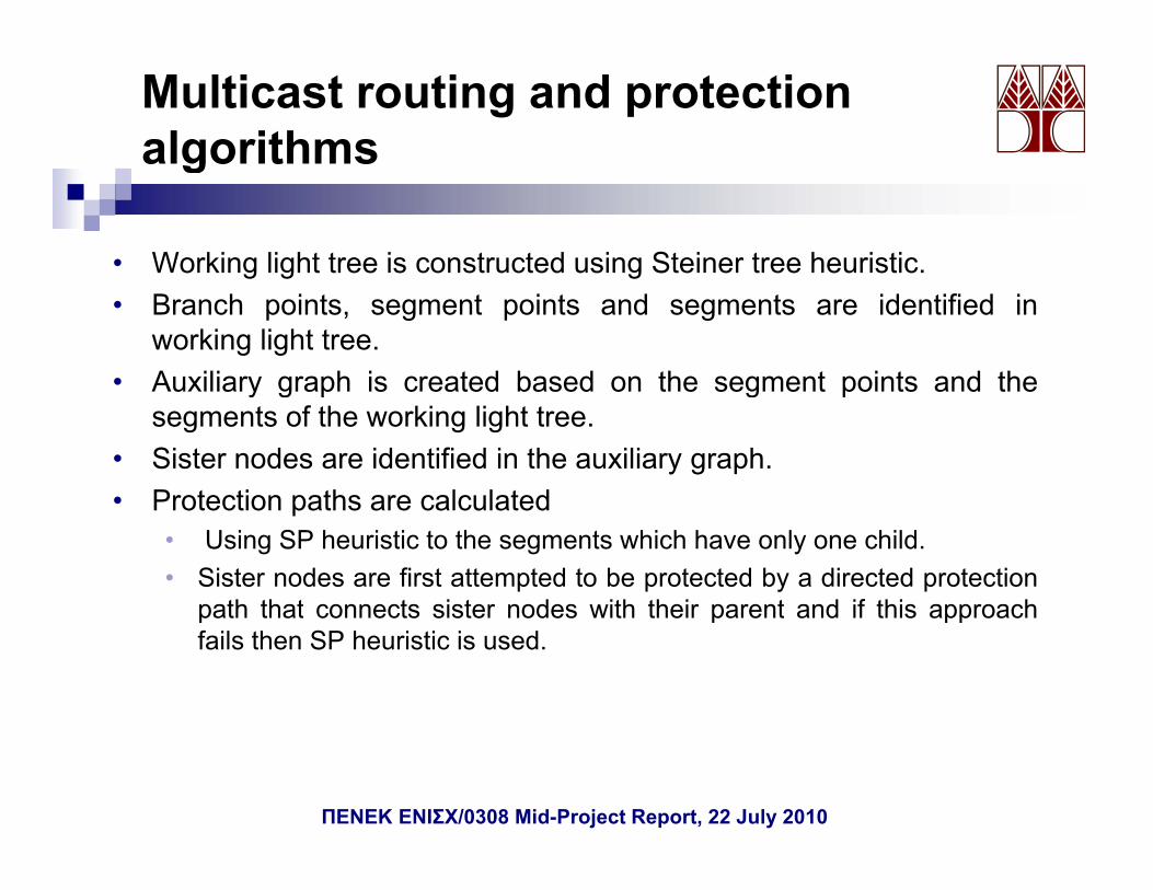
Multicast routing and protection algorithmsg
• Working light tree is constructed using Steiner tree heuristic.g g g• Branch points, segment points and segments are identified in
working light tree.• Auxiliary graph is created based on the segment points and theAuxiliary graph is created based on the segment points and the
segments of the working light tree.• Sister nodes are identified in the auxiliary graph.• Protection paths are calculated• Protection paths are calculated
• Using SP heuristic to the segments which have only one child.• Sister nodes are first attempted to be protected by a directed protection
path that connects sister nodes with their parent and if this approachpath that connects sister nodes with their parent and if this approachfails then SP heuristic is used.
ΠΕΝΕΚ ΕΝΙΣΧ/0308 Mid-Project Report, 22 July 2010
Multicast routing and protection algorithmsg
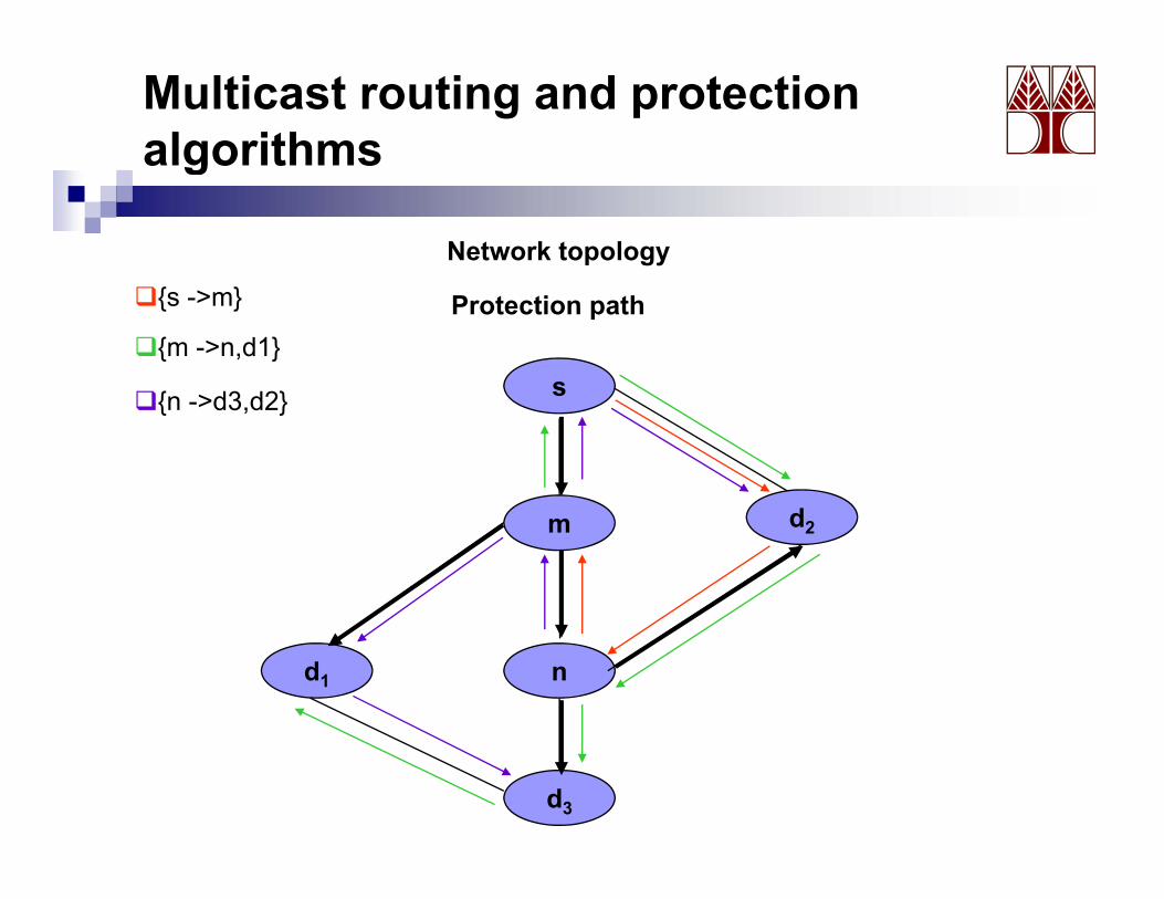
Network topology
s
Protection path{s ->m}
{m ->n,d1}
{ d3 d2} s{n ->d3,d2}
m d2
nd1
d3
Multicast routing and protection algorithmsg
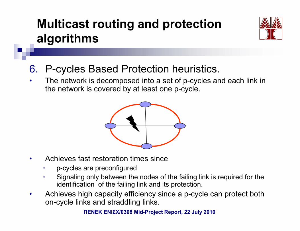
6. P-cycles Based Protection heuristics.6. P cycles Based Protection heuristics.• The network is decomposed into a set of p-cycles and each link in
the network is covered by at least one p-cycle.
• Achieves fast restoration times since• Achieves fast restoration times since• p-cycles are preconfigured • Signaling only between the nodes of the failing link is required for the
identification of the failing link and its protection.• Achieves high capacity efficiency since a p-cycle can protect both
on-cycle links and straddling links.ΠΕΝΕΚ ΕΝΙΣΧ/0308 Mid-Project Report, 22 July 2010
Multicast routing and protection algorithmsg
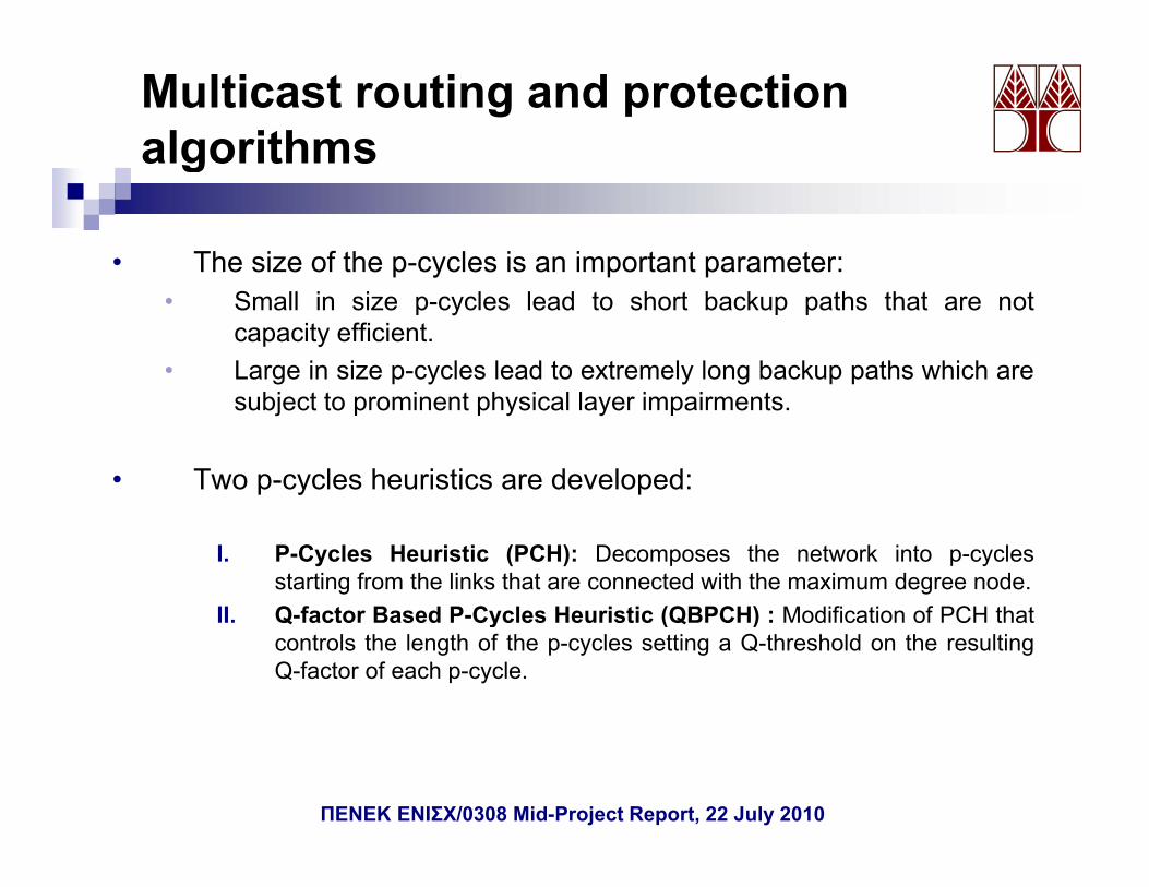
• The size of the p-cycles is an important parameter:p y p p• Small in size p-cycles lead to short backup paths that are not
capacity efficient.• Large in size p-cycles lead to extremely long backup paths which are
subject to prominent physical layer impairments.
• Two p-cycles heuristics are developed:
I. P-Cycles Heuristic (PCH): Decomposes the network into p-cyclesstarting from the links that are connected with the maximum degree node.
II Q factor Based P Cycles Heuristic (QBPCH) : Modification of PCH thatII. Q-factor Based P-Cycles Heuristic (QBPCH) : Modification of PCH thatcontrols the length of the p-cycles setting a Q-threshold on the resultingQ-factor of each p-cycle.
ΠΕΝΕΚ ΕΝΙΣΧ/0308 Mid-Project Report, 22 July 2010
Multicast routing and protection algorithmsg
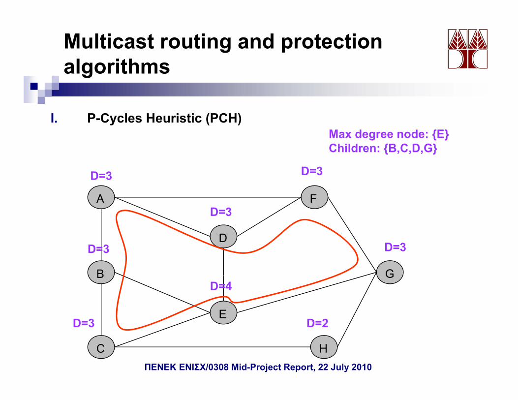
I. P-Cycles Heuristic (PCH)y ( )Max degree node: {E}Children: {B,C,D,G}
D=3 D=3
FA
D=3 D 3
D=3
D
B G
D=3 D=3
B
E
G
D=3
D=4
D=2
C H
D 3 D 2
ΠΕΝΕΚ ΕΝΙΣΧ/0308 Mid-Project Report, 22 July 2010
Multicast routing and protection algorithmsg
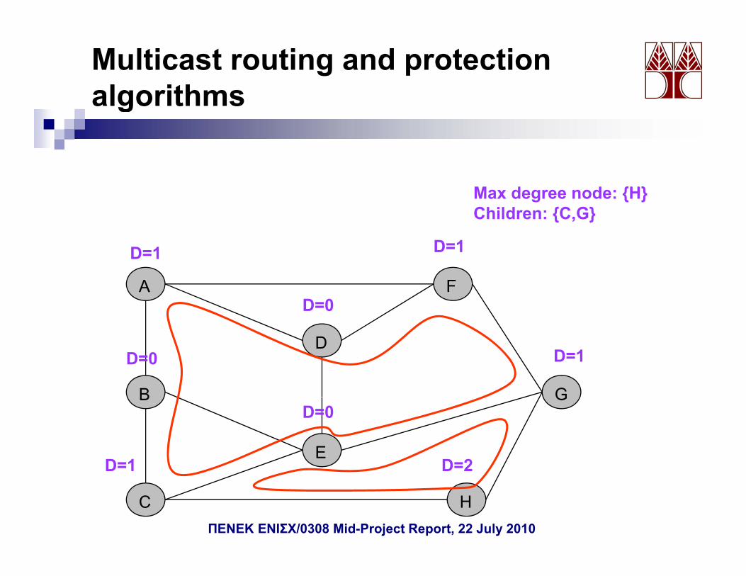
Max degree node: {H}Children: {C,G}
D=1 D=1
FA
D=1 D 1
D=0
D
B G
D=0 D=1
B
E
G
D=1
D=0
D=2
C H
D 1 D 2
ΠΕΝΕΚ ΕΝΙΣΧ/0308 Mid-Project Report, 22 July 2010
Multicast routing and protection algorithmsg
Max degree node: {A}Children: {F}
D=1 D=1Terminates since A and F belong to the same p-cycle.
FA
D=1 D 1
D=0
D
B G
D=0 D=0
B
E
G
D=0
D=0
D=0
C H
D 0 D 0
ΠΕΝΕΚ ΕΝΙΣΧ/0308 Mid-Project Report, 22 July 2010
Multicast routing and protection algorithmsg
II. Q-factor Based P-Cycles Heuristic (QBPCH)y ( )
• Controls the length of the p-cycles by taking into account thephysical layer constraints.physical layer constraints.
• Modification of PCH:• Sets a Q-threshold.• Calculates the Q factor on each constructed p cycle starting from the• Calculates the Q-factor on each constructed p-cycle starting from the
maximum degree node and if Q is below the predeterminedthreshold then it deletes consequently nodes from the p-cycle,starting from the last node, until the calculated Q-factor is above theQ-threshold.
• Deleted nodes are taken into account for the creation of next p-cycles.
ΠΕΝΕΚ ΕΝΙΣΧ/0308 Mid-Project Report, 22 July 2010
Simulation Parameters
Network :• 50 nodes• 50 nodes•196 bidirectional links•average node degree of 3.92•maximum node degree of 6•an average distance between the links of 60 Km
Dynamic System:• Poisson arrivals•Exponentially distributed holding times with a unit meanExponentially distributed holding times with a unit mean.•100 Erlangs load. •For each run 5.000 requests were generated for each multicast group size.•The results for each simulation point were obtained as the average of 5 runs .
64 l th d t 100 GH tili d64 wavelengths spaced at 100 GHz were utilizedQ threshold was set at 8.5 dBQ which corresponds to a BER of 10-12 .Node architecture and engineering design of fixed Txs/Rxs (case 1) was assumed.
ΠΕΝΕΚ ΕΝΙΣΧ/0308 Mid-Project Report, 22 July 2010
Simulation Results
• Blocking probability versus the multicast group size without physical layert i t
0 91
constraints.
0,60,70,80,9
ckin
g
MC-CRMCHSP
0,20,30,40,5
Pr. b
loc
SSNFLEVELPCH
00,1
4 7 10 13 16 19 22 25
QBPCH
multicast group size
ΠΕΝΕΚ ΕΝΙΣΧ/0308 Mid-Project Report, 22 July 2010
Simulation Results
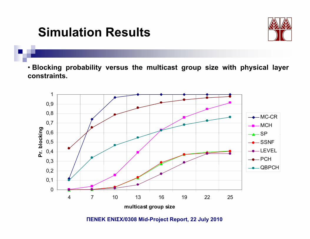
• Blocking probability versus the multicast group size with physical layert i tconstraints.
0 9
1
0,6
0,7
0,8
0,9
ing
MC-CRMCHSP
0,3
0,4
0,5
,
Pr. b
lock
SPSSNFLEVELPCH
0
0,1
0,2 QBPCH
4 7 10 13 16 19 22 25
multicast group size
ΠΕΝΕΚ ΕΝΙΣΧ/0308 Mid-Project Report, 22 July 2010
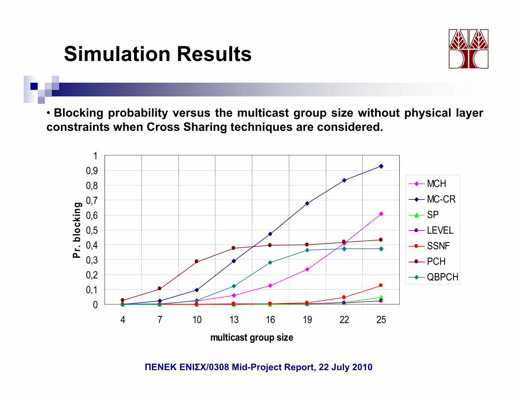
Simulation Results
• Blocking probability versus the multicast group size without physical layert i t h C Sh i t h i id d
0,91
constraints when Cross Sharing techniques are considered.
0,60,70,8,
ckin
g
MCHMC-CRSP
0 20,30,40,5
Pr. b
loc LEVEL
SSNFPCHQBPCH
00,10,2
4 7 10 13 16 19 22 25
QBPCH
multicast group size
ΠΕΝΕΚ ΕΝΙΣΧ/0308 Mid-Project Report, 22 July 2010
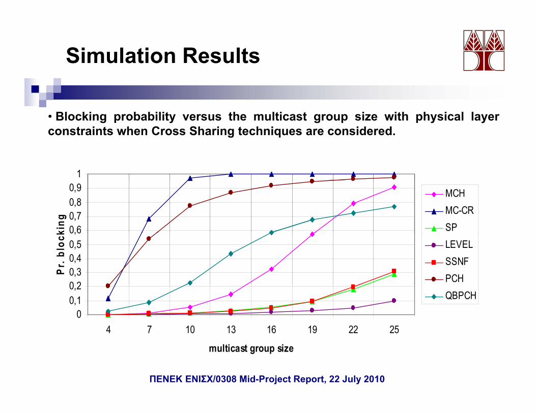
Simulation Results
• Blocking probability versus the multicast group size with physical layert i t h C Sh i t h i id d
1
constraints when Cross Sharing techniques are considered.
0,60,70,80,9
king
MCHMC-CRSP
0 20,30,40,50,6
Pr. b
lock
LEVELSSNFPCH
00,10,2
4 7 10 13 16 19 22 25
QBPCH
multicast group size
ΠΕΝΕΚ ΕΝΙΣΧ/0308 Mid-Project Report, 22 July 2010
Work Package 5RWA with grooming under PLCs (5-month duration)g g ( )
Development of a simulation code that performs theti / i d l th i t d h i l lrouting/grooming and wavelength assignment under physical layer
constraints.A node Architecture capable of grooming was designed.Development of novel traffic grooming techniques for multicastDevelopment of novel traffic grooming techniques for multicastconnections while taking into account the transmission effects:
Grooming with Maximum Overlapped Lightpath (GMOL) heuristic.GMOL heuristic with constraints on the number of hops.
Where different grooming policies were taken into consideration:Where different grooming policies were taken into consideration:Sequential Single-Hop provisioningSequential Multi-Hop provisioningNon-Restricted Sequential Multi- Hop ProvisioningHybrid ProvisioningHybrid Provisioning
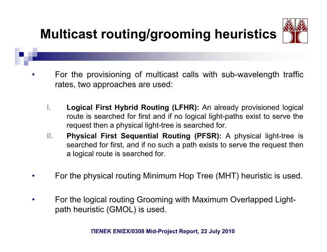
For the provisioning of multicast calls with sub-wavelength traffic rates, twoapproaches were used:
Logical First Hybrid Routing (LFHR)Physical First Sequential Routing (PFSR)Physical First Sequential Routing (PFSR)
ΠΕΝΕΚ ΕΝΙΣΧ/0308 Mid-Project Report, 22 July 2010
Introduction
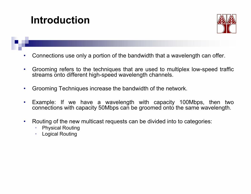
• Connections use only a portion of the bandwidth that a wavelength can offer.
• Grooming refers to the techniques that are used to multiplex low-speed trafficstreams onto different high-speed wavelength channels.
• Grooming Techniques increase the bandwidth of the network.
• Example: If we have a wavelength with capacity 100Mbps, then twoconnections with capacity 50Mbps can be groomed onto the same wavelength.connections with capacity 50Mbps can be groomed onto the same wavelength.
• Routing of the new multicast requests can be divided into to categories:• Physical Routing• Logical Routing• Logical Routing
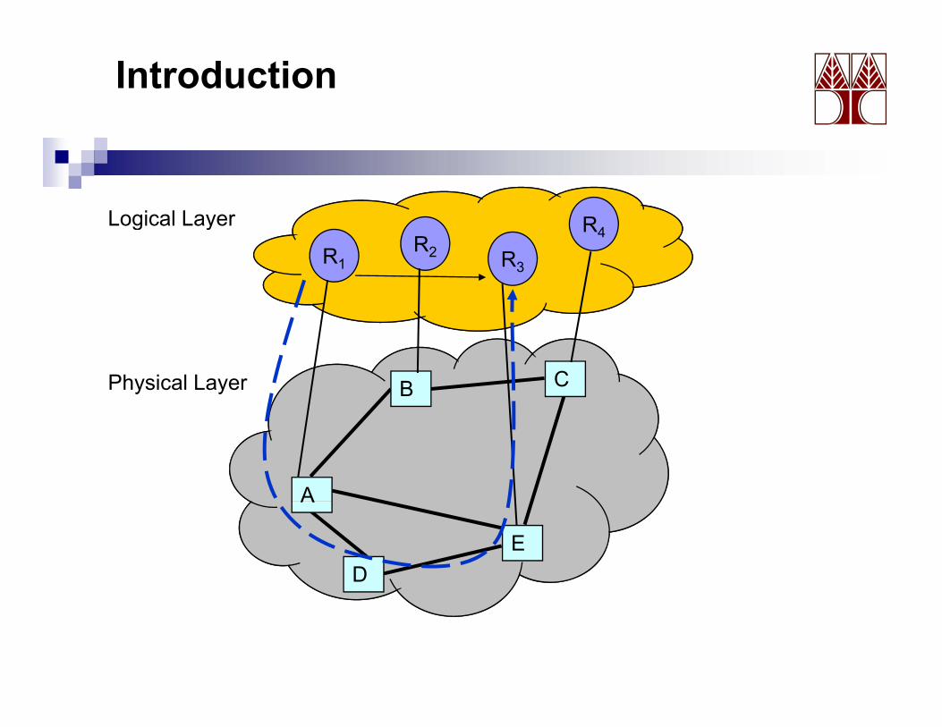
Introduction
RLogical Layer
R3R1R2
R4g y
CBPhysical Layer
A
ED
A
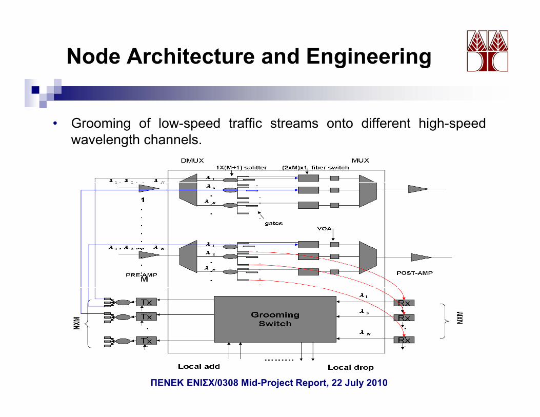
Node Architecture and Engineering
• Grooming of low-speed traffic streams onto different high-speedg p g pwavelength channels.
ΠΕΝΕΚ ΕΝΙΣΧ/0308 Mid-Project Report, 22 July 2010
Multicast Grooming Policies
1. Sequential Single-Hop Provisioning: An already establishedq g p g ylight-tree, with the same source and reaching the same set ofdestinations, with sufficient bandwidth is used to provision thearriving session.a g sess o
2. Sequential Multi-Hop Provisioning: An already established light-tree serving the same set of destinations but with traffic from adifferent source, with sufficient bandwidth is used to provision thedifferent source, with sufficient bandwidth is used to provision thearriving session. One more light-tree that connects source nodewith the source node of the logical light-tree is needed.
3. Non-Restricted Sequential Multi-Hop Provisioning: An already3. Non Restricted Sequential Multi Hop Provisioning: An alreadyestablished light-tree serving only a subset of the destinations withtraffic from a different source or with traffic from the same source,with sufficient bandwidth is used to provision the arriving session.gSeveral hops may be needed to serve the entire arriving session.
ΠΕΝΕΚ ΕΝΙΣΧ/0308 Mid-Project Report, 22 July 2010
Multicast routing/grooming heuristics
• For the provisioning of multicast calls with sub-wavelength trafficp g grates, two approaches are used:
I. Logical First Hybrid Routing (LFHR): An already provisioned logicalg y g ( ) y p groute is searched for first and if no logical light-paths exist to serve therequest then a physical light-tree is searched for.
II. Physical First Sequential Routing (PFSR): A physical light-tree ish d f fi d if h h i h hsearched for first, and if no such a path exists to serve the request then
a logical route is searched for.
F th h i l ti Mi i H T (MHT) h i ti i d• For the physical routing Minimum Hop Tree (MHT) heuristic is used.
• For the logical routing Grooming with Maximum Overlapped Light-path heuristic (GMOL) is used.
ΠΕΝΕΚ ΕΝΙΣΧ/0308 Mid-Project Report, 22 July 2010
Multicast routing/grooming heuristics
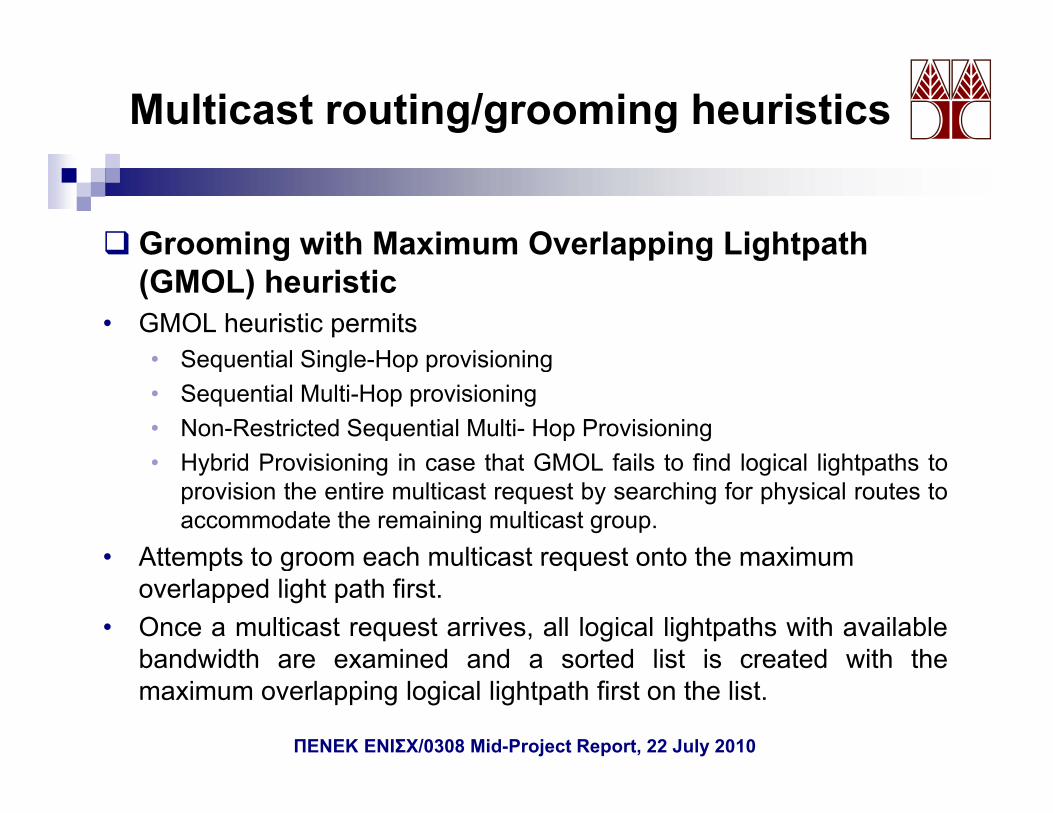
Grooming with Maximum Overlapping LightpathGrooming with Maximum Overlapping Lightpath (GMOL) heuristic
• GMOL heuristic permitsSequential Single Hop provisioning• Sequential Single-Hop provisioning
• Sequential Multi-Hop provisioning• Non-Restricted Sequential Multi- Hop Provisioning
H brid Pro isioning in case that GMOL fails to find logical lightpaths to• Hybrid Provisioning in case that GMOL fails to find logical lightpaths toprovision the entire multicast request by searching for physical routes toaccommodate the remaining multicast group.
• Attempts to groom each multicast request onto the maximumAttempts to groom each multicast request onto the maximum overlapped light path first.
• Once a multicast request arrives, all logical lightpaths with availablebandwidth are examined and a sorted list is created with thebandwidth are examined and a sorted list is created with themaximum overlapping logical lightpath first on the list.
ΠΕΝΕΚ ΕΝΙΣΧ/0308 Mid-Project Report, 22 July 2010
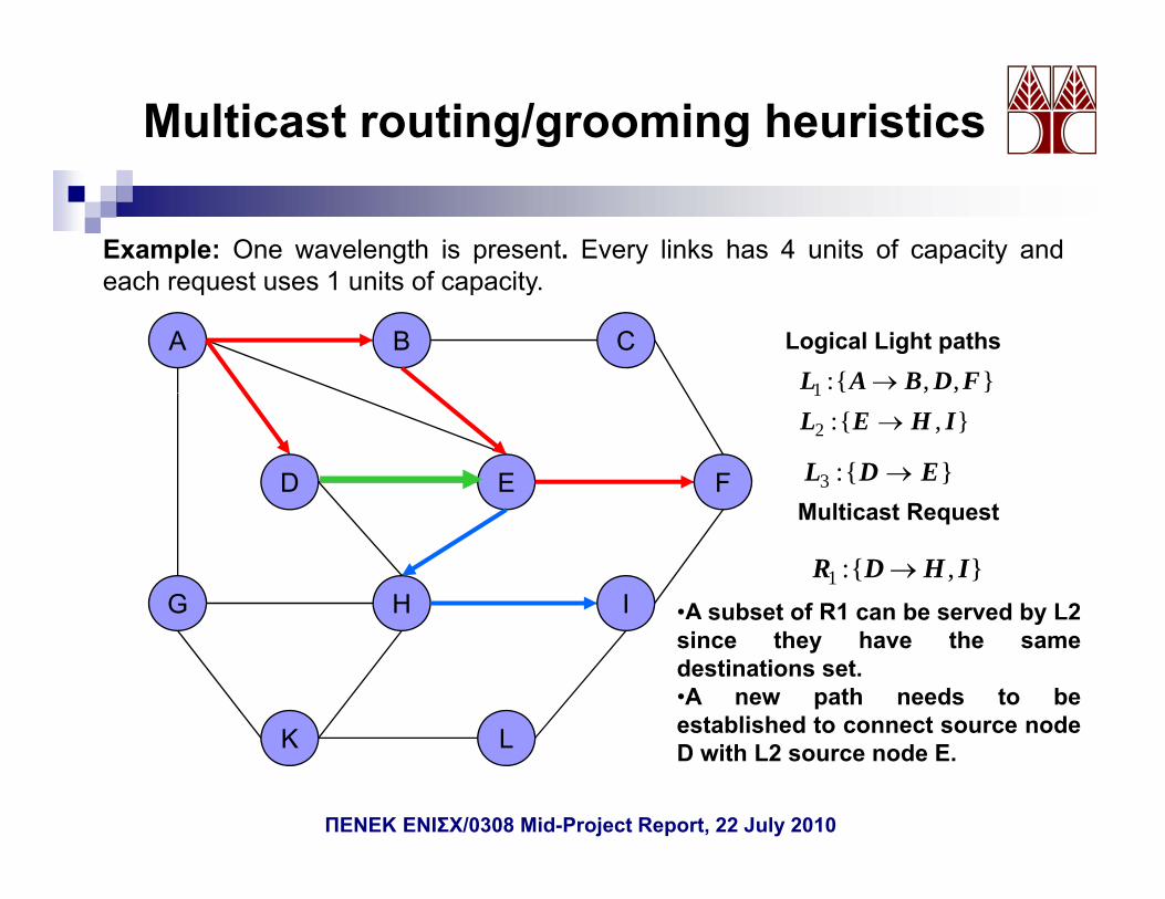
Multicast routing/grooming heuristics
Example: One wavelength is present. Every links has 4 units of capacity andeach request uses 1 units of capacity
},,{:1 FDBAL →
Logical Light pathsA B C
each request uses 1 units of capacity.
M lti t R t
},,{1
},{:2 IHEL →
D E F }{:3 EDL →
},{:1 IHDR →
Multicast Request
G H I •A subset of R1 can be served by L2
K L
subset o ca be se ed bysince they have the samedestinations set.•A new path needs to beestablished to connect source nodeK L D with L2 source node E.
ΠΕΝΕΚ ΕΝΙΣΧ/0308 Mid-Project Report, 22 July 2010
Multicast routing/grooming heuristics
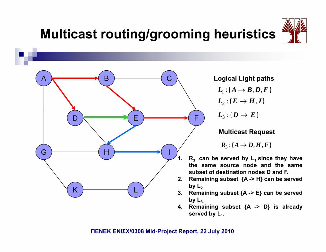
Logical Light pathsA B C},,{:1 FDBAL →
},{:2 IHEL →
Logical Light pathsA B C
Multicast Request
D E F }{:3 EDL →
},,{:3 FHDAR →G H I
1. R3 can be served by L1 since they havethe same source node and the samesubset of destination nodes D and F.
K L
subset of destination nodes D and F.2. Remaining subset {A -> H} can be served
by L2.3. Remaining subset {A -> E} can be served
by L3.4 R i i b t {A > D} i l d4. Remaining subset {A -> D} is already
served by L1.
ΠΕΝΕΚ ΕΝΙΣΧ/0308 Mid-Project Report, 22 July 2010
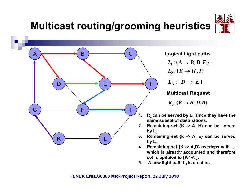
Multicast routing/grooming heuristics
Logical Light pathsA B C
}{:3 EDL →
},,{:1 FDBAL →
},{:2 IHEL →
D E F }{3
},,{:3 BDHKR →
Multicast RequestD E
G H I
F
G H I1. R3 can be served by L1 since they have the
same subset of destinations.2. Remaining set {K -> A, H} can be served
by L2.
K Lby L2.
3. Remaining set {K -> A, E} can be servedby L3.
4. Remaining set {K -> A,D} overlaps with L1which is already accounted and thereforeset is pdated to {K >A }set is updated to {K->A }.
5. A new light path L4 is created.
ΠΕΝΕΚ ΕΝΙΣΧ/0308 Mid-Project Report, 22 July 2010
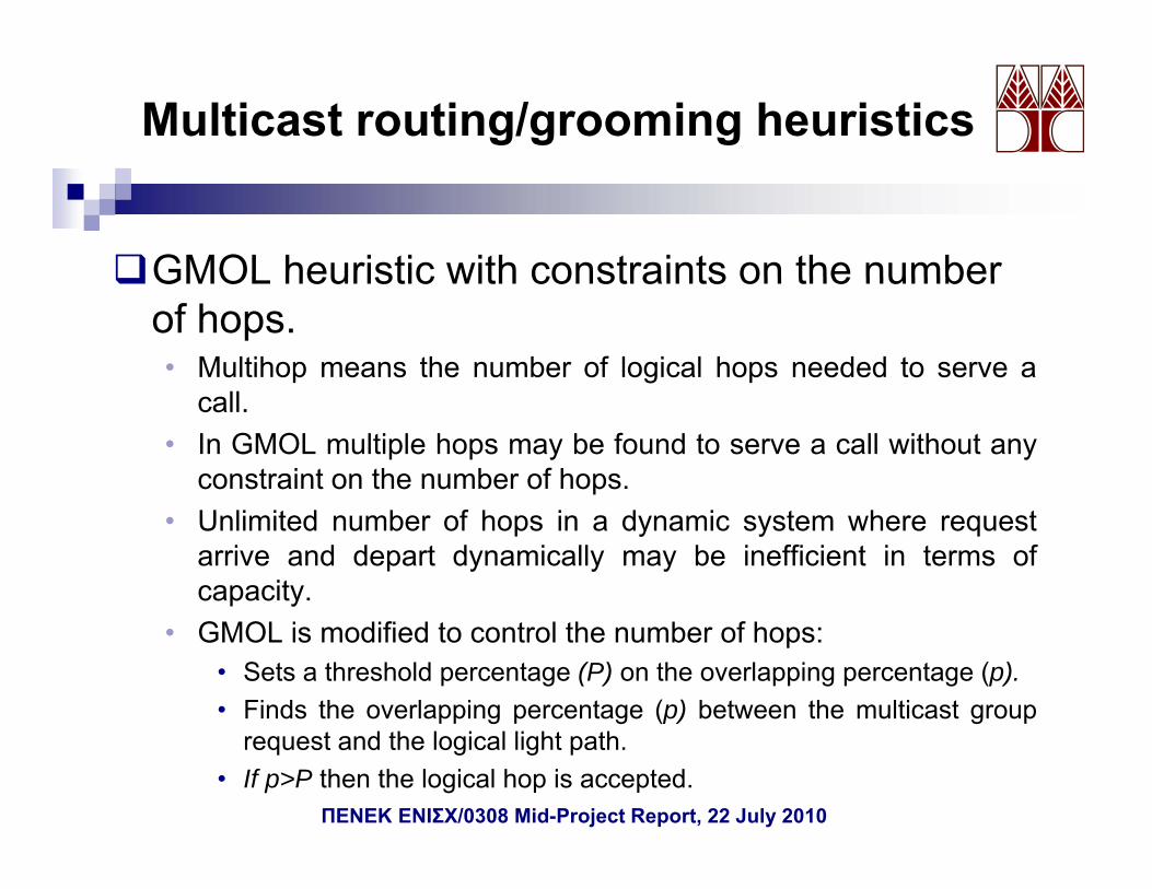
Multicast routing/grooming heuristics
GMOL heuristic with constraints on the numberGMOL heuristic with constraints on the number of hops.• Multihop means the number of logical hops needed to serve a
call.• In GMOL multiple hops may be found to serve a call without any
constraint on the number of hops.• Unlimited number of hops in a dynamic system where request
arrive and depart dynamically may be inefficient in terms ofcapacity.
• GMOL is modified to control the number of hops:• Sets a threshold percentage (P) on the overlapping percentage (p).• Finds the overlapping percentage (p) between the multicast group
request and the logical light path.• If p>P then the logical hop is accepted.
ΠΕΝΕΚ ΕΝΙΣΧ/0308 Mid-Project Report, 22 July 2010
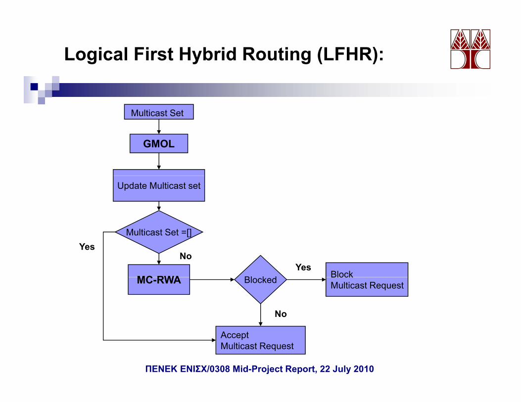
Logical First Hybrid Routing (LFHR):
Multicast Set
GMOL
Update Multicast set
Multicast Set =[]
MC RWA Bl k d Block
NoYes
YesMC-RWA Blocked Block
Multicast Request
No
AcceptMulticast Request
ΠΕΝΕΚ ΕΝΙΣΧ/0308 Mid-Project Report, 22 July 2010
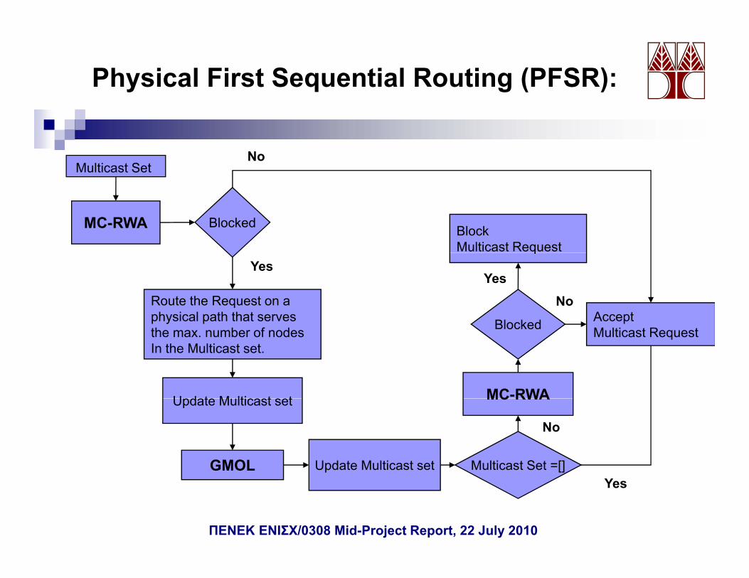
Physical First Sequential Routing (PFSR):
Multicast SetNo
MC-RWA Blocked BlockMulticast Request
Route the Request on aphysical path that serves Blocked Accept
qYes
YesNo
the max. number of nodesIn the Multicast set.
Update M lticast set MC-RWA
Blocked Multicast Request
Update Multicast set
GMOL Update Multicast set Multicast Set =[]
MC RWA
No
p []Yes
ΠΕΝΕΚ ΕΝΙΣΧ/0308 Mid-Project Report, 22 July 2010
Simulation Parameters
Network :• 50 nodes• 50 nodes•196 bidirectional links•average node degree of 3.92•maximum node degree of 6•an average distance between the links of 60 Km
Dynamic System:• Poisson arrivals•Exponentially distributed holding times with a unit meanExponentially distributed holding times with a unit mean.•100 Erlangs load. • The rate of each request is an integer randomly generated between the set o integer [1-10].F h 5 000 t t d f h lti t i•For each run 5.000 requests were generated for each multicast group size.
•The results for each simulation point were obtained as the average of 5 runs .32 wavelengths spaced at 100 GHz were utilized.Each wavelength is assumed to have 10 units of capacityg p yQ threshold was set at 8.5 dBQ which corresponds to a BER of 10-12 .Fixed Txs/Rxs of case 1 node engineering was assumed.
ΠΕΝΕΚ ΕΝΙΣΧ/0308 Mid-Project Report, 22 July 2010
Simulation Results
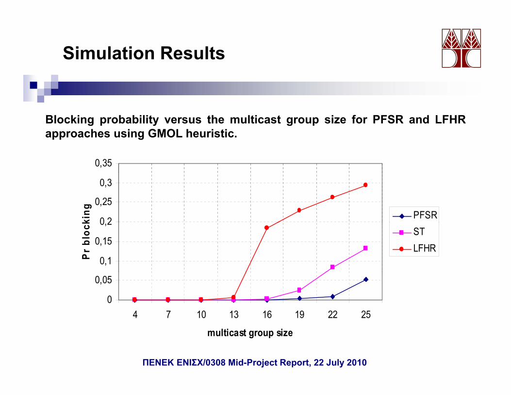
Blocking probability versus the multicast group size for PFSR and LFHR
0,35
Blocking probability versus the multicast group size for PFSR and LFHRapproaches using GMOL heuristic.
0 2
0,25
0,3
king PFSR
0,1
0,15
0,2
Pr b
lock ST
LFHR
0
0,05
4 7 10 13 16 19 22 25
multicast group size
ΠΕΝΕΚ ΕΝΙΣΧ/0308 Mid-Project Report, 22 July 2010
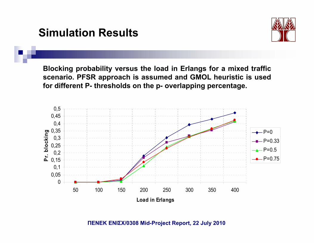
Simulation Results
Blocking probability versus the load in Erlangs for a mixed traffici PFSR h i d d GMOL h i ti i dscenario. PFSR approach is assumed and GMOL heuristic is used
for different P- thresholds on the p- overlapping percentage.
0 30,350,4
0,450,5
ing P=0
0 10,150,2
0,250,3
Pr.
bloc
ki P=0.33P=0.5P=0.75
00,050,1
50 100 150 200 250 300 350 400
L d i E lLoad in Erlangs
ΠΕΝΕΚ ΕΝΙΣΧ/0308 Mid-Project Report, 22 July 2010
Work Package 6RWA for GC connections with PLCs
Development of a simulation code that performs the routing andp p gwavelength assignment of groupcast requests under physical layerconstraints.Development of three groupcast routing algorithms:p g p g g
Light-Trees heuristicLight-Paths heuristicLinear Light-Trees heuristicg
ΠΕΝΕΚ ΕΝΙΣΧ/0308 Mid-Project Report, 22 July 2010
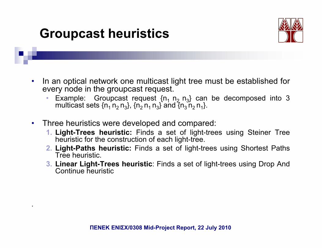
Groupcast heuristics
• In an optical network one multicast light tree must be established forevery node in the groupcast request.• Example: Groupcast request {n1 n2 n3} can be decomposed into 3
multicast sets {n1 n2 n3}, {n2 n1 n3} and {n3 n2 n1}.{ 1 2 3}, { 2 1 3} { 3 2 1}
• Three heuristics were developed and compared:1. Light-Trees heuristic: Finds a set of light-trees using Steiner Tree
heuristic for the construction of each light-treeheuristic for the construction of each light-tree.2. Light-Paths heuristic: Finds a set of light-trees using Shortest Paths
Tree heuristic.3. Linear Light-Trees heuristic: Finds a set of light-trees using Drop And
Continue heuristicContinue heuristic
.
ΠΕΝΕΚ ΕΝΙΣΧ/0308 Mid-Project Report, 22 July 2010
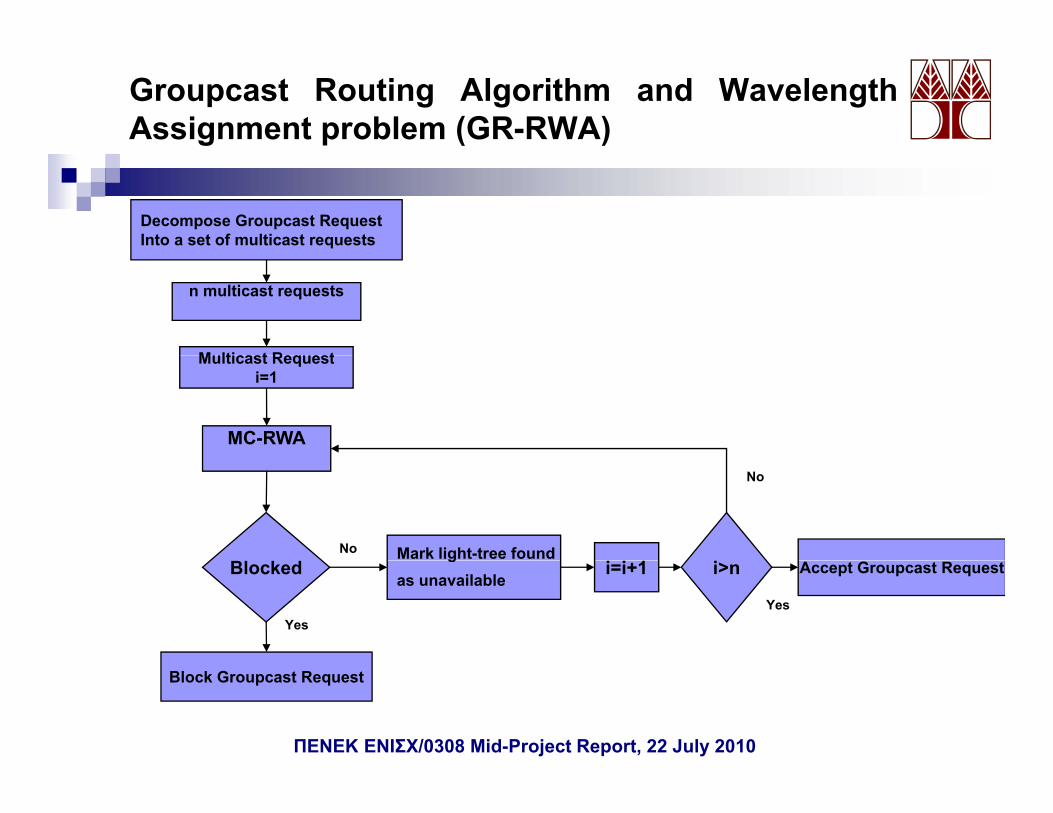
Groupcast Routing Algorithm and WavelengthAssignment problem (GR-RWA)
Decompose Groupcast RequestInto a set of multicast requests
n multicast requests
Multicast Request
MC-RWA
Multicast Requesti=1
Mark light-tree foundNo
No
Blockedg
as unavailablei=i+1 i>n Accept Groupcast Request
YesYes
Block Groupcast Request
ΠΕΝΕΚ ΕΝΙΣΧ/0308 Mid-Project Report, 22 July 2010
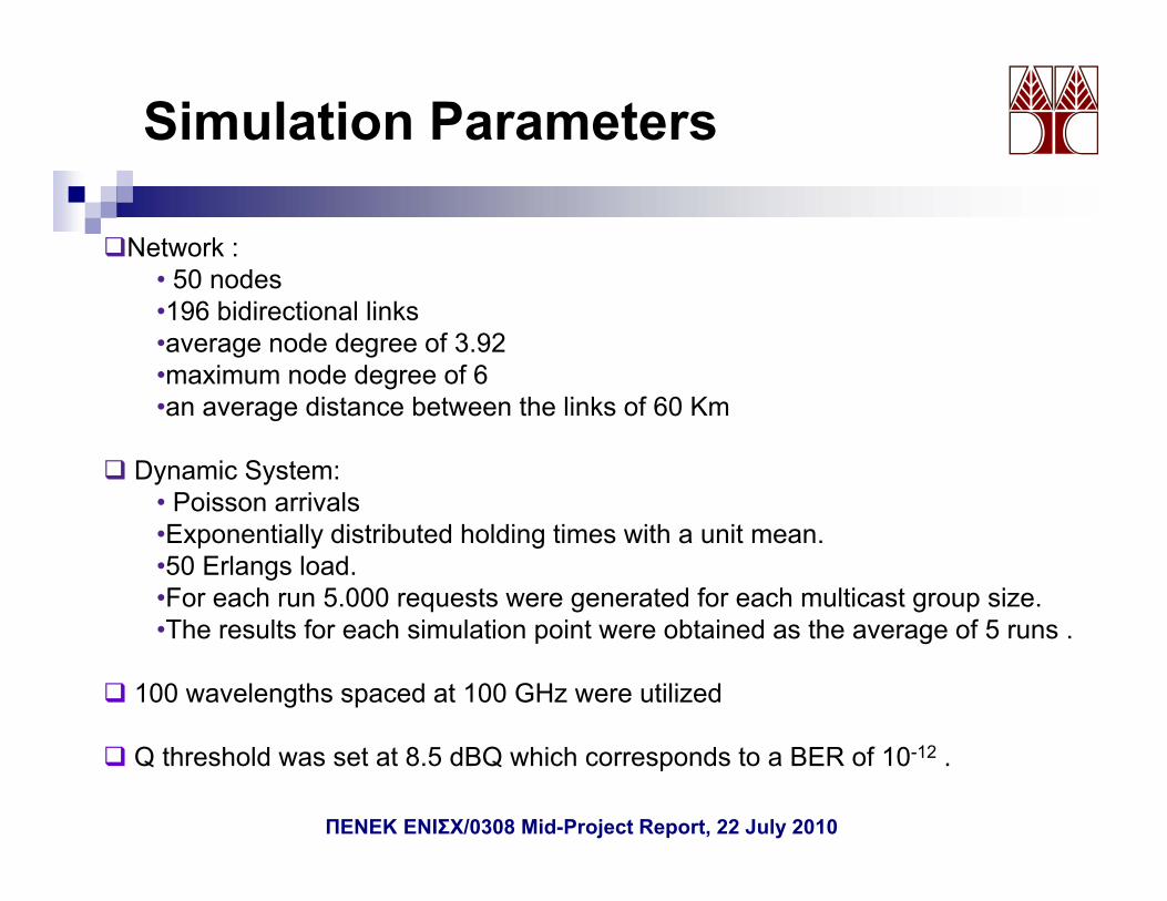
Simulation Parameters
Network :• 50 nodes• 50 nodes•196 bidirectional links•average node degree of 3.92•maximum node degree of 6•an average distance between the links of 60 Km
Dynamic System:• Poisson arrivalsPoisson arrivals•Exponentially distributed holding times with a unit mean.•50 Erlangs load. •For each run 5.000 requests were generated for each multicast group size.Th lt f h i l ti i t bt i d th f 5•The results for each simulation point were obtained as the average of 5 runs .
100 wavelengths spaced at 100 GHz were utilized
Q threshold was set at 8.5 dBQ which corresponds to a BER of 10-12 .
ΠΕΝΕΚ ΕΝΙΣΧ/0308 Mid-Project Report, 22 July 2010
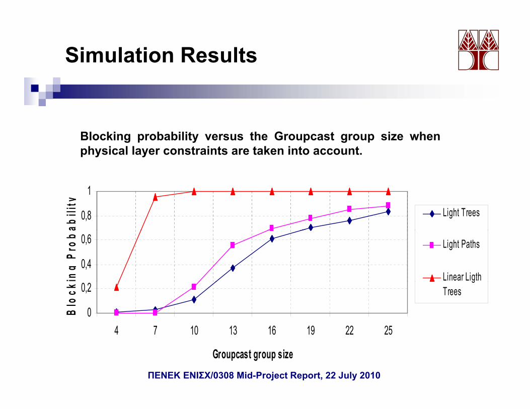
Simulation Results
Blocking probability versus the Groupcast group size whenphysical layer constraints are taken into account.
0,8
1
abili
ty
Light Trees
0,4
0,6
ing
Prob
a
Light Paths
Linear Ligth
0
0,2
4 7 10 13 16 19 22 25
Blo
ck
gTrees
4 7 10 13 16 19 22 25
Groupcast group sizeΠΕΝΕΚ ΕΝΙΣΧ/0308 Mid-Project Report, 22 July 2010
Summary
• Several novel and noteworthy results were obtained during the implementation of WPs 3-5 including:• Novel QoT-Based MC-RWA algorithms• Novel node design and network engineering approaches• Novel QoT-based protection techniques for multicast connections• Novel QoT-based grooming techniques for multicast connections
• No major problems were observed during the implementation of the first half of the project
• No deviation from the original timetable is expected for the remaining work-packages and deliverables.• Work-package 6 has been completedWork package 6 has been completed • Research is currently progressing on work-package 7
Top Related