


γλώσσες
Σελίδες
Νομικός

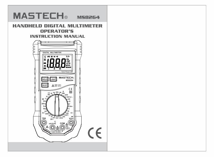
MS8264 HANDHELD DIGITAL MULTIMETER
OPERATOR'S INSTRUCTION MANUAL
MS8264HOLD LIGHT
10A
COM
FUSED,10A MAXRESETTABLE
750V1000V
MAX
600V CAT III1000V CAT II
hFEmA
Hz
200m
FEh
20020k 200k 2M
20M200M
200m
1000
20n
2µ
20µ
2m
10
2k
20
2
200
750
200
20
2
10200m 20m
200n
20kHz
°C
°C
Ω
ON/OFF
1. GENERAL INSTRUCTIONS.......................11.1 Precaution safety measures......................1 1.1.1 Preliminary......................................1 1.1.2 During use........................................2 1.1.3 Symbols...........................................4 1.1.4 Instructions......................................51.2 Protection mechanisms............................5
2. DESCRIPTION...........................................62.1 Instrument Familiarization.........................62.2 LCD Display..............................................72.3 Keypad.....................................................82.4 Terminals..................................................92.5 Accessories..............................................9
3. FUNCTION DESCRIPTION......................103.1 General Functions..................................10 3.1.2 ..........10 3.1.3 Battery saver........3.2 Measurement Functions
DATA HOLD mode..........................................10.........................10
3.2.1 AC and DC Voltage measurement................10
CONTENTS CONTENTS
3.2.2 Resistance measurement...............11
3.2.3 Diode Test......................................133.2.4 Continuity Check............................14
3.2.5 Capacitance measurement 3.2.6 Transistor measurement...
3.2.7 Frequency measurement.................16
4. TECHNICAL SPECIFICATIONS4.1 General specifications4.2 Measurement specifications 4.2.1 DC Voltage 4.2.2 AC Voltage 4.2.3 Frequency......................................21 4.2.4 Resistance 4.2.5 Diode Test........... 4.2.6 Continuity Check 4.2.7 Transistor
4.2.9 Capacitance 4.2.10 DC current 4.2.11 AC current..
5. MAINTENANCE5.1 General Maintenance5.2 Battery Replacement
............15.............16
..............19............................19
...................20....................................20....................................20
....................................21..........................21
...........................22........................................22
..................................22
....................................23..................................23
.....................................24..................................24..................................25
4.2.8 Temperature....................................22
3.2.9 Current measurement.....................18
3.2.8 Temperature measurement..............17
01 02
1. General Instructions This instrument complies with IEC 1010-1 (61010-1 @IEC: 2001), CAT. II 1000V and CAT. III 600V over voltage standards. See Specifications. To get the best service from this instrument, read carefully this user's manual and respect the detailed safety precautions. International symbols used on the Meter and in this manual are explained in chapter 1.1.3
1.1 Precautions Safety Measures
Measurement category III is for measurements performed in the building installation. NOTE: Examples are measurements on distribution boards, circuit-breakers, wiring, including cables, bus-bars, junction boxes, switches, socket-outlets in the fixed installation, and equipment for industrial use and some other equipment, for example, stationary motors with permanent connection to the fixed installation.
Measurement category II is for measurements performed on circuits directly connected to the low voltage installation. NOTE: Examples are measurements on household appliances, portable tools and similar equipment.
Measurement category I is for measurements performed on circuits not directly connected to MAINS. NOTE: Examples are measurements on circuits not derived from MAINS, and specially protected (internal)
*
*
*
MAINS derived circuits. In the latter case, transient stresses are variable; for that reason, requires that the transient withstand capability of the equipment is made known to the user.
1.1.1 Preliminary
* When using this Multimeter, the user must observe all normal safety rules concerning:- protection against the dangers of electric current.- protection of the Multimeter against misuse.* For your own safety, only use the test probes supplied with the instrument. Before use, check that they are in good condition.
* If the meter is used near noise generating equipment, be aware that display may become unstable or indicate large errors.* Do not use the meter or test leads if they look damaged. * Use the meter only as specified in this manual; otherwise, the protection provided by the meter may be impaired.* Use extreme caution when working around bare conductors or bus bars.* Do not operate the meter around explosive gas, vapor, or dust.* Verify a Meter's operation by measuring a known voltage. Do not use the Meter if it operates abnormally. Protection may be impaired. When in doubt, have the Meter serviced.* Uses the proper terminals, function, and range for your measurements. * When the range of the value to be measured is unknown, check that the range initially set on the multimeter is the highest possible or, wherever possible, choose the autoranging mode.
1.1.2 During use
03 04
* To avoid damages to the instrument, do not exceed the maximum limits of the input values shown in the technical specification tables.
When the multimeter is linked to measurement circuits, do not touch unused terminals.
Caution when working with voltages above 60Vdc or 30Vac rms. Such voltages pose a shock hazard.
When using the probes, keep your fingers behind the finger guards.
When making connections, connect the common test lead before connecting the live test lead; when disconnecting, disconnect the live test lead before disconnecting the common test lead.
Before changing functions, disconnect the test leads from the circuit under test.
For all dc functions, including manual or auto-ranging, to avoid the risk of shock due to possible improper reading, verify the presence of any ac voltages by first using the ac function. Then select a dc voltage range equal to or greater than the ac range.
Disconnect circuits power and discharge all high-voltage capacitors before testing resistance, continuity, diodes, or capacitance.
Never perform resistance or continuity measurements on live circuits.
Before measuring current, check the meter's fuse and turn off power to the circuit before connecting the meter to the circuit.
In TV repair work, or when carrying out measurements on power switching circuits, remember that high amplitude voltage pulses at the test points can damage the multimeter. Use of a TV filter will attenuate any such pulses.
*
*
*
*
*
*
*
*
*
*
* Use the 9V NEDA battery, properly installed in the Meter's battery case, to power the Meter.* Replace the battery as soon as the battery indicator ( ) appears. With a low battery, the Meter might produce false readings that can lead to electric shock and personal injury.* Do not measure voltages above 600V in Category III, or 1000V in Category II installations. * Do not operate the Meter with the case (or part of the case) removed.
Symbols used in this manual and on the instrument:
1.1.3 Symbols:
Caution: refer to the instruction manual. Incorrect use may result in damage to the device or its components.
AC (Alternating Current)
DC (Direct Current)
Earth ground
Double insulated
Fuse
Conforms to European Union directives
05 06
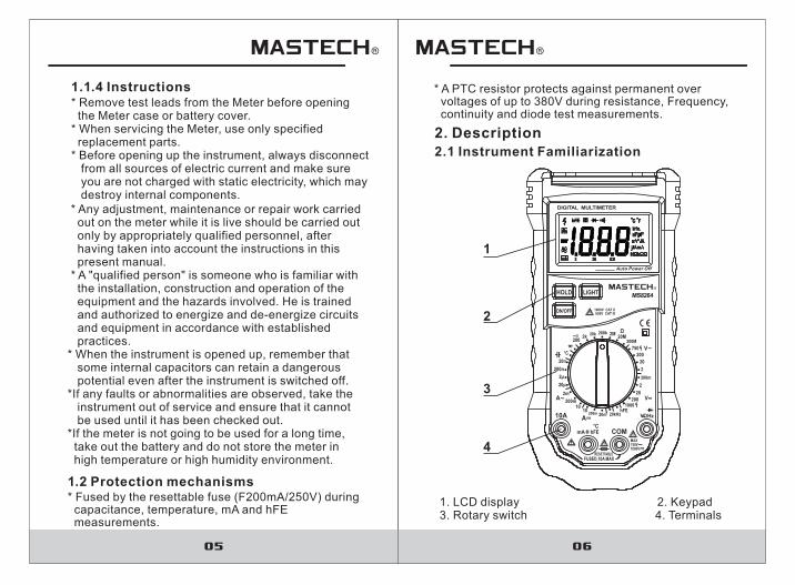
* Any adjustment, maintenance or repair work carried out on the meter while it is live should be carried out only by appropriately qualified personnel, after having taken into account the instructions in this present manual. * A "qualified person" is someone who is familiar with the installation, construction and operation of the equipment and the hazards involved. He is trained and authorized to energize and de-energize circuits and equipment in accordance with established practices.* When the instrument is opened up, remember that some internal capacitors can retain a dangerous potential even after the instrument is switched off.*If any faults or abnormalities are observed, take the instrument out of service and ensure that it cannot be used until it has been checked out.*If the meter is not going to be used for a long time, take out the battery and do not store the meter in high temperature or high humidity environment.
A PTC resistor protects against permanent over voltages of up to 380V during resistance, Frequency, continuity and diode test measurements.
*
1.2 Protection mechanisms
2. Description2.1 Instrument Familiarization
1. LCD display 2. Keypad 3. Rotary switch 4. Terminals
* Remove test leads from the Meter before opening the Meter case or battery cover.* When servicing the Meter, use only specified replacement parts.* Before opening up the instrument, always disconnect from all sources of electric current and make sure you are not charged with static electricity, which may destroy internal components.
1.1.4 Instructions
Hz
POWER
HOLD LIGHT
DIGITAL MULTIMETER MS8264
AC
C FC F
DC
mV V
mA
A
kHz
nF F
hFE
A
kM2 20 200
600V CAT III1000V CAT II
C
UNFUSED,10A MAX
RESETTABLE
750V
1000V
MAX
FEh
200
20k 200k 2M20M
200M
200m
1000
20n
2
20
2m
10
200m
2k
20
2
200
750
200
20
2
10200m 20m
200n
20kHz
CV
V
A
A
FEhmA
V
Auto Power Off
10A
COM
2
1
3
4
MS8264
ON/OFF
HOLD LIGHT
10A
COM
FUSED,10A MAXRESETTABLE
750V1000V
MAX
600V CAT III1000V CAT II
hFEmA
Hz
200m
FEh
20020k 200k 2M
20M200M
200m
1000
20n
2µ
20µ
2m
10
2k
20
2
200
750
200
20
2
10200m 20m
200n
20kHz
°C
°C
Ω
* Fused by the resettable fuse (F200mA/250V) during capacitance, temperature, mA and hFE measurements.
07 08
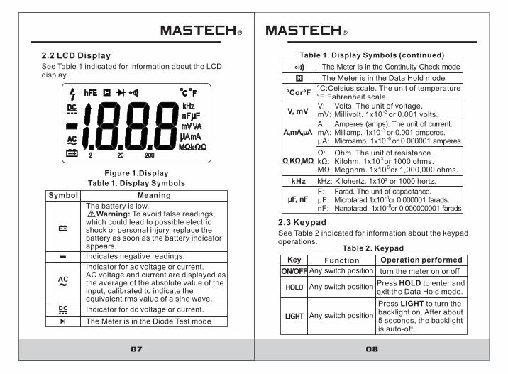
See Table 1 indicated for information about the LCD display.
2.2 LCD Display
Figure 1.Display
Table 1. Display Symbols
MeaningSymbol
The battery is low. Warning: To avoid false readings, which could lead to possible electric shock or personal injury, replace the battery as soon as the battery indicator appears.
Indicates negative readings.
The Meter is in the Diode Test mode
Table 1. Display Symbols (continued)
V:mV:
Volts. The unit of voltage.Millivolt. 1x10 or 0.001 volts.-3
A:mA:μA:
Amperes (amps). The unit of current.Milliamp. 1x10 or 0.001 amperes.Microamp. 1x10 or 0.000001 amperes
-3
-6
k :M :
Ω:ΩΩ
Ohm. The unit of resistance.Kilohm. 1x10 or 1000 ohms.Megohm. 1x10 or 1,000,000 ohms.
3
6
F::
n :µF
F
Farad. The unit of capacitance.Microfarad.1x10 or 0.000001 farads.Nanofarad. 1x10 or 0.000000001 farads
-6
-9
See Table 2 indicated for information about the keypad operations.
2.3 Keypad
Table 2. Keypad
FunctionKey
Any switch position
Operation performed
turn the meter on or off
Press HOLD to enter and exit the Data Hold mode.
Any switch position
V, mV
A,mA,µA
Ω,ΚΩ,ΜΩ
µF, nF
HOLD
ON/OFF
Any switch position
Press LIGHT to turn thebacklight on. After about 5 seconds, the backlightis auto-off.
LIGHTIndicator for dc voltage or current.
kHz kHz: Kilohertz. 1x10³ or 1000 hertz.
Indicator for ac voltage or current. AC voltage and current are displayed as the average of the absolute value of theinput, calibrated to indicate the equivalent rms value of a sine wave.
AC~
DC
The Meter is in the Continuity Check mode
The Meter is in the Data Hold mode
°Cor°F°C:Celsius scale. The unit of temperature°F:Fahrenheit scale.
09 10
See Table 4 indicated for information about the terminals.
2.4 Terminals
Table 4. Terminals
DescriptionTerminal
Return terminal for all measurements. (Receiving the black test lead or the “com” plug of the special multi-function socket)
Input for voltage, resistance, frequency, diode and continuity measurements. (Receiving the red test lead)
Input for capacitance, Temperature, hFE and 0.001mA to 200mA currentmeasurements. (Receiving the red test lead or the “+” plug of the special multi-function socket)
Input for 200mA to 10A current measurements. (Receiving the red test lead)
Delivered with the multimeter:
2.5 Accessories
One piece• User's manual
One piece
One piece
• Test leads
• Special Multi-function socket
3. Function Description3.1 General Functions 3.1.1 DATA HOLD Mode
Data Hold mode makes the meter stop updating thedisplay. Data Hold function can be cancelled by changing the measurement mode, or push HOLD key again.To enter and exit the Data Hold mode: 1. Press HOLD key Fixes the display on the current value, is displayed.2. A second short press returns the meter to normal mode.
H
COM
VΩHz
°C mAhFE
10A
• K”type bead Thermocouple One piece
3.1.2 Battery Saver
Turn on the meter. And then The meter will be turnedoff automatic after approx.30 minutes.
3.2 Measurement Functions
3.2.1 AC and DC Voltage measurement
To avoid electrical shock and/or damage tothe instrument, do not attempt to take anyvoltage measurement that might exceeds 1000Vdc or 750Vac rms. To avoid electrical shock and/or damage tothe instrument, do not apply more than 1000Vdc or 750Vac rms between the common terminal and the earth ground.
• Carry case One piece
11
To measure resistance:1. Set the rotary switch to proper range.2. Connect the black and red test leads to the COM and terminals respectively.3. Connect the test leads to the circuit being measured and read the displayed value.
Some tips for measuring resistance:
The measured value of a resistor in a circuit is oftendifferent from the resistor's rated value. This is because the Meter's test current flows through allpossible paths between the probe tips.In order to ensure the best accuracy in measurementof low resistance, short the test leads beforemeasurement and memory the test probe resistancein mind. This necessary to subtract for the resistanceof the test leads.The resistance function can produce enough voltageto forward-bias silicon diode or transistor junctions, causing them to conduct. To avoid this, do not use the40MΩ range for in-circuit resistance measurements.On 20MΩ and 200MΩ ranges, the meter may take a few seconds to stabilize reading. This is normal forhigh resistance measuring.On 200MΩ range, the display is approx. 10 digits whentest leads are shorted. These 10 digits have to be subtracted from measuring results. For example, whenmeasuring 100 M resistance, the reading will be 101.0and the correct measuring result should be 101.0-1.0=100.0 MΩ.When the input is not connected, i.e. at open circuit, the figure "1" will be displayed for the overrangecondition.
Ω
Voltage is the difference in electrical potential between two points. The polarity of ac (alternating current) voltage varies over time; the polarity of dc (direct current)voltage is constant.The Meter's DC voltage ranges are 200.0mV, 2.000V, 20.00V, 200.0V and 1000.V;AC voltage ranges are 2.000V, 20.00V, 200.0V and 7500V.To measure ac or dc voltage:1. Set rotary switch to the proper range.2. Connect the black and red test leads to the COM and V terminals respectively.3. Connect the test leads to the circuit being measured 4. Read the displayed value. The polarity of red test lead connection will be indicated when making a DCV measurement.
Note:
Unstable display may occur especially at DC200mV and AC2V ranges, even though you do not put test leads into input terminals, in this case, if an erroneous reading is suspected, short the V terminal and the COM terminal, and make sure the zero display.
3.2.2 Resistance Measurement
To avoid electrical shock and/or damage tothe instrument, disconnect circuit powerand discharge all high-voltage capacitorsbefore measuring resistance.
ΩResistance is an opposition to current flow.The unit of resistance is the ohm ( ). The Meter's resistance ranges are 200.0Ω, 2.000kΩ, 20.00kΩ, 200.0kΩ, 2.000MΩ, 20.00MΩ and 200.0MΩ.
12
13 14
3.2.3 Diode Test
To avoid electrical shock and/or damage tothe instrument, disconnect circuit powerand discharge all high-voltage capacitors before testing diodes.
Use the diode test to check diodes, and other semi- conductor devices. The diode test sends a current through the semiconductor junction, and then measures the voltage drop across the junction; a good silicon junction drops between 0.5V and 0.8V.To test a diode out of a circuit:1. Set the rotary switch to range.2. Connect the black and red test leads to the COM and terminals respectively.3. For forward-bias readings on any semiconductor component, place the red test lead on the component's anode and place the black test lead on the component's cathode.4. The meter will show the approx. forward voltage of the diode. If the test lead connection is reversed, only figure "1" displayed. In a circuit, a good diode should still produce a forward bias reading of 0.5V to 0.8V; however, the reverse-bias reading can vary depending on the resistance of other pathways between the probe tips.
3.2.4 Continuity Check
To avoid electrical shock and/or damage tothe instrument, disconnect circuit power and discharge all high-voltage capacitors before testing for Continuity.
Continuity is a complete path for current flow. The beeper sounds if a circuit is complete. These brief contacts cause the Meter to emit a short beep. To test for continuity:1. Set the rotary switch to range.2. Press the yellow key twice to activate Continuity Check.3. Connect the black and red test leads to the COM and terminals respectively.4. Connect the test leads to the resistance in the circuit being measured.5. When the test lead to the circuit is below approx. 30Ω, a continuous beeping will indicate it.
Note:• Continuity test is available to check open/short of the circuit.
Ω
3.2.5 Capacitance Measurement
To avoid electrical shock and/or damage to the instrument, disconnect circuit power and discharge all high-voltage capacitors before measuring capacitance. Use the dc voltagefunction to confirm that the capacitor is discharged.
15 16
Capacitance is the ability of a component to store an electrical charge.The unit of capacitance is the farad (F). Most capacitors are in the nanofarad to microfarad range. The Meter's capacitance ranges are 20 00nF, 200 0nF, 2 000µF, To measure capacitance:1. Set the rotary switch to proper range.2. Connect the black and red test leads to the COM and terminals respectively (or you can measure the capacitance by using the special Multi-Function Socket). 3. Connect the test leads to the capacitor being measured and read the displayed value.
. .. and 20.00µF.
Some tips for measuring capacitance:
The meter may take a few seconds to stabilize reading. This is normal for high capacitance measuring.To improve the accuracy of measurements less than 20nF, subtract the residual capacitance of the Meterand leads.
3.2.6 Transistor Measurement
To avoid electrical shock and/or damage to the instrument, do not apply more than 250Vdc or 250Vac rms between the hFE terminal and the COM terminal.
1. Set the rotary switch to hFE range.2. Connect the “com” plug and “+” plug of the special multi-function socket to the COM and hFE terminals. 3. Determine whether the transistor to be tested is NPN or PNP type and locate the Emitter, Base and Collector leads.4. Insert leads of the transistor into proper holes of the special multi-function socket. 5. The meter will show the approx. hFE value at test condition of base current 10μA and Vce 2.8V.
3.2.7 Frequency Measurement
Do not measure Frequency on high voltage (>380V) to avoid electrical shock hazard and/or damage to the instrument.
Frequency is the number of cycles a voltage or currentsignal completes each second.To measure frequency:1. Set the rotary switch to 20kHz range.2. Connect the black and red test leads to the COM and Hz terminals respectively.3. Connect the test leads to the circuit being measured 4. Read the displayed value.
17 18
Current is the flow of electrons through a conductor.The Meter's DC current ranges are 20 00mA, 200.0mA and 10.00A;AC current ranges are 2.000mA, 200.0mA and 10.00A.To measure current:1. Turn off the power of the measured circuit. Discharge all the high voltage capacitors. 2. Set the rotary switch to the proper range.3. Connect the black test lead to the COM terminal and the red test leads to the mA terminal for a maximum of 200mA. For a maximum of 10A, move the red test lead to the 10A terminal.4. Break the circuit path to be tested. Connect the black test lead to the more negative side of the break; connect the red test lead to the more positive side of the break. (Reversing the leads will give a negative reading, but will not damage the Meter.)
.
5. Turn on the power of the measured circuit, and then read the display. Be sure to note the
3.2.9 Current Measurement
To avoid damage to the Meter or injury if thefuse blows, never attempt an in-circuit current measurement where the open-circuit potentialto earth is greater than 250V.To avoid damage to the meter, check the meter's fuse before proceeding. Use the proper terminals, function, and range for yourmeasurement. Never place the test leads inparallel with a circuit or component when theleads are plugged into the current terminals.
3.2.8 Temperature Measurement
To avoid electrical shock and/or damage to the instrument, do not apply more than 250Vdc or 250Vac rms between the °Cterminal and the COM terminal.To avoid electrical shock, do not use this instrument when voltages at the measurement surface exceed 60v dc or 24v rms. Ac. To avoid damage or burns. Do not maketemperature measurements in microwaveovens.
To measure temperature:1. Set the rotary switch to range and the LCD will show the current environment temperature.2. Connect the “com” plug and “+” plug of the special multi-function socket to the COM and hFE terminals.3. Insert ‘K’ type thermocouples into the special multi-function socket, Takings care to observe the correct polarity.4. Touch the object with the thermocouple probe for measurement. 5. Read the stable reading from LCD.
°C
19 20
measurement units at the right side of the display (mA or A). When only the figure "1" displayed, it indicates overrange situation and the higher range has to be selected.6. Turn off the power of the measured circuit and discharge all the high voltage capacitors. Remove the test leads and recover the measured circuit.
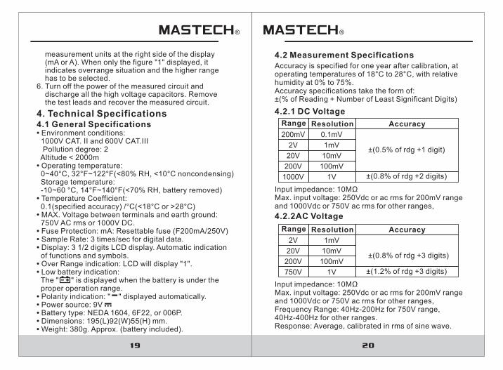
4. Technical Specifications4.1 General Specifications• Environment conditions: 1000V CAT. II and 600V CAT.III Pollution degree: 2 Altitude < 2000m• Operating temperature: 0~40°C, 32°F~122°F(<80% RH, <10°C noncondensing) Storage temperature: -10~60 °C, 14°F~140°F(<70% RH, battery removed)• Temperature Coefficient: 0.1(specified accuracy) /°C(<18°C or >28°C)• MAX. Voltage between terminals and earth ground: 750V AC rms or 1000V DC.• Fuse Protection: mA: Resettable fuse (F200mA/250V) • Sample Rate: 3 times/sec for digital data.• Display: 3 1/2 digits LCD display. Automatic indication of functions and symbols.• Over Range indication: LCD will display "1".• Low battery indication: The " " is displayed when the battery is under the proper operation range.• Polarity indication: " " displayed automatically.• Power source: 9V• Battery type: NEDA 1604, 6F22, or 006P.• Dimensions: 195(L)92(W)55(H) mm.• Weight: 380g. Approx. (battery included).
Accuracy is specified for one year after calibration, at operating temperatures of 18°C to 28 C, with relative humidity at 0% to 75%.Accuracy specifications take the form of: ±(% of Reading + Number of Least Significant Digits)
°
4.2 Measurement Specifications
4.2.1 DC Voltage
ResolutionRange
0.1mV
Accuracy
±(0.5% of rdg +1 digit)
200mV
1mV
10mV
100mV
1V
2V
20V
200V
1000V ±(0.8% of rdg +2 digits)
4.2.2AC Voltage
Input impedance: 10MΩMax. input voltage: 250Vdc or ac rms for 200mV range and 1000Vdc or 750V ac rms for other ranges,
ResolutionRange Accuracy
±(0.8% of rdg +3 digits)
1mV
10mV
100mV
1V
2V
20V
200V
750V ±(1.2% of rdg +3 digits)
Input impedance: 10MMax. input voltage: 250Vdc or ac rms for 200mV rangeand 1000Vdc or 750V ac rms for other ranges, Frequency Range: 40Hz-200Hz for 750V range, 40Hz-400Hz for other ranges.Response: Average, calibrated in rms of sine wave.
Ω

21 22
4.2.4 Resistance
ResolutionRange Accuracy
±(0.8% of rdg +1 digit)
1Ω
10Ω
100Ω
1kΩ
200Ω
2kΩ
20kΩ
200kΩ
2MΩ
20MΩ
200MΩ
10kΩ
0.1MΩ± 5.0% of (+10 digits]
[ rdg-10digits)
±(0.8% of rdg +3 digits)
Overload protection: 380V dc or 380Vac rms.Open Circuit Voltage: Less than 700mV.
0.1Ω
4.2.5 Diode
ResolutionRange Function
1mVDisplay read approx. forward voltage of diode
Forward DC Current: approx. 1mAReversed DC Voltage: approx. 2.8VOverload protection: 250Vdc or 380Vac rms.
4.2.6 Audible continuity
Continuity beeperRange
≤30Ω
Open circuit voltage: Less than 700mV.Overload protection: 380Vdc or 380Vac rms.
4.2.7 Transistor
DescriptionRange Test Condition
Display read approx. HFE value (0-1000) of transistor under test (all type).
Base Current approx. 10µA, Vce approx. 2.8V.
hFE
4.2.9 Capacitance
ResolutionRange Accuracy
10pF
0.1nF
1nF
10nF
2nF
20nF
20 0µF.
±(4.0% of rdg +3 digit )s
Overload protection: Resettable fuse (F200mA/250V).
1pF
Overload protection: Resettable fuse (F200mA/250V).* Temperature specifications do not include thermocouple errors.
2 0µF.
4.2.3 Frequency
ResolutionRange
Overload protection: 380V dc or 380V ac rms.Input Voltage range: 200mV-10V ac rms
±(1.5% of rdg + 5 digits)20kHz 10Hz
Accuracy
4.2.8 Temperature
ResolutionRange Accuracy
-20°C~0°C ±(5.0% of rdg +4 digit )s
±(1.0% of rdg +3 digit )s±2.0% of rdg
1°C~400°C
401°C~1000°C
1°C
200nF
23 24
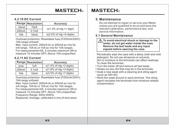
4.2.10 DC Current
ResolutionRange Accuracy
10mA
200mA
10A ±(2.0% of rdg +5 digits)
Overload protection: Resettable fuse (F200mA/250V).10A range unfusedMax. input current: 200mA dc or 200mA ac rms formA range, 10A dc or 10A ac rms for 10A ranges.For measurements>5A, 4 minutes maximum ON tomeasure 10 minutes OFF; Above 10A unspecified.
10μA20mA±(1.5% of rdg +1 digit)
4.2.11 AC Current
ResolutionRange Accuracy
10mA
200mA
10A ±(3.0% of rdg +7 digits)
Overload protection: Resettable fuse (F200mA/250V). 10A range Max. input current: 200mA dc or 200mA ac rms for mA range, 10A dc or 10A ac rms for 10A ranges.For measurements>5A, 4 minutes maximum ON to measure 10 minutes OFF; Above 10A unspecified.Frequency Range: 40Hz-400HzResponse: Average, calibrated in rms of sine wave
unfused
1μA2mA ±(1.0% of rdg +3 digits)
±(1.8% of rdg +3 digits)
5. MaintenanceDo not attempt to repair or service your Meter unless you are qualified to do so and have the relevant calibration, performance test, and service information.
5.1 General Maintenance
To avoid electrical shock or damage to the meter, do not get water inside the case. Remove the test leads and any inputsignals before opening the case.
Periodically wipe the case with a damp cloth and mild detergent. Do not use abrasives or solvents.Dirt or moisture in the terminals can affect readings.To clean the terminals:
• Turn the meter off and remove all test leads.• Shake out any dirt that may be in the terminals.• Soak a new swab with a cleaning and oiling agent (such as WD-40).• Work the swab around in each terminal. The oiling agent insulates the terminals from moisture-related contamination.
0.1mA
0.1mA
25 26
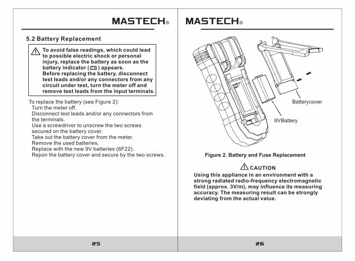
5.2 Battery Replacement
To avoid false readings, which could lead to possible electric shock or personal injury, replace the battery as soon as thebattery indicator ( ) appears.Before replacing the battery, disconnect test leads and/or any connectors from any circuit under test, turn the meter off andremove test leads from the input terminals.
To replace the battery (see Figure 2): Turn the meter off. Disconnect test leads and/or any connectors from the terminals. Use a screwdriver to unscrew the two screws secured on the battery cover. Take out the battery cover from the meter. Remove the used batteries. Replace with the new 9V batteries (6F22). Rejoin the battery cover and secure by the two screws.
Using this appliance in an environment with a strong radiated radio-frequency electromagnetic field (approx. 3V/m), may influence its measuring accuracy. The measuring result can be strongly deviating from the actual value.
CAUTION
Battery cover
9V Battery
Figure 2. Battery and Fuse Replacement

HYS006659
Top Related