


γλώσσες
Σελίδες
Νομικός

JPEG: Still Image Compression StandardStandard
Topics today…
IntroductionTh JPEG L l C di Al i hThe JPEG Lossless Coding AlgorithmBaseline JPEG CompressionProgressive DCT-Based ModeHierarchical Mode
Multimedia Computing (CSIT 410) 2
I t d tiIntroduction
JPEG is the first image compression JPEG is the first image compression standard for continuous tone still imagesgAcronym for Joint Photographic Experts Groupp pOfficially referred to as
ISO/IEC IS (International Standard) 10918-1: Digital Compression and Coding of Continuous-tone Still ImagesITU T Recommendation T 81ITU-T Recommendation T.81
Multimedia Computing (CSIT 410) 3
I t d tiIntroduction [2]
Goal of the standard is to support a variety of applications for compression of continuous-tone still images of most image sizes in any color space in order to achieve compression performance at or achieve compression performance at or near the state-of-the-art with user-adjustable compression ratios and with adjustable compression ratios and with very good to excellent reconstructed quality
Multimedia Computing (CSIT 410) 4
I t d tiIntroduction [3]
JPEG d fi f d f iJPEG defines four modes of operation
1 Sequential Lossless Mode: Compress the image in a1. Sequential Lossless Mode: Compress the image in asingle scan and the decoded image is an exactreplica of the original image.
2. Sequential DCT-based Mode: Compress the imagein a single scan using DCT-based lossy compressiontechnique As a result the decoded image is not antechnique. As a result, the decoded image is not anexact replica, but an approximation of the originalimage.
Multimedia Computing (CSIT 410) 5
I t d tiIntroduction [4]
3. Progressive DCT-based Mode: Compress theimage in multiple scans and alsod th i i lti l ithdecompress the image in multiple scans witheach successive scan producing a better-quality image.
4. Hierarchical Mode: Compress the image atmultiple resolutions for display on differentd idevices.
Multimedia Computing (CSIT 410) 6
I t d tiIntroduction [5]
Modes 2 3 and 4 are lossyModes 2, 3 and 4 are lossyMode 1 uses predictive coding with no quantization hence losslessquantization, hence losslessSequential DCT-based JPEG algorithm
In it’s simplest form called baseline JPEGIn it s simplest form called baseline JPEGalgorithm, which is based on Huffman coding for entropy encoding (2)The other form is based on arithmetic coding for entropy encoding (3)
Multimedia Computing (CSIT 410) 7
The JPEG Lossless Coding Algorithm
Based on the principle of predictiveBased on the principle of predictivecoding, a simple method for spatialredundancy reductionThe difference between the actual pixelvalue and the predicted value is called thedifferential or the prediction error value &is entropy encoded using a variable-length encoding techniquelength encoding techniqueDifferential Pulse Code Modulation (DPCM)
Multimedia Computing (CSIT 410) 8
The JPEG Lossless Coding Algorithm [2]
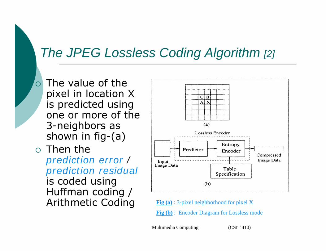
The value of the pixel in location X is predicted using gone or more of the 3-neighbors as shown in fig-(a)g ( )Then the prediction error / prediction residualprediction residualis coded using Huffman coding / Arithmetic Coding Fig (a) : 3-pixel neighborhood for pixel XArithmetic Coding
Multimedia Computing (CSIT 410)
g ( ) p g p
Fig (b) : Encoder Diagram for Lossless mode
The JPEG Lossless Coding Algorithm [3]
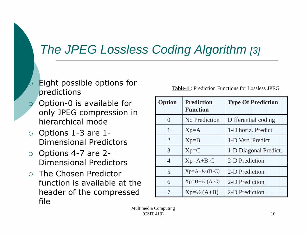
Eight possible options for predictionsOption-0 is available for Option Prediction Type Of Prediction
Table-1 : Prediction Functions for Lossless JPEG
Option-0 is available for only JPEG compression in hierarchical modeOptions 1-3 are 1-
Option Prediction Function
Type Of Prediction
0 No Prediction Differential coding
1 Xp=A 1-D horiz. PredictOptions 1-3 are 1-Dimensional PredictorsOptions 4-7 are 2-Dimensional Predictors
p
2 Xp=B 1-D Vert. Predict
3 Xp=C 1-D Diagonal Predict.
4 Xp=A+B-C 2-D PredictionDimensional PredictorsThe Chosen Predictor function is available at the header of the compressed
p
5 Xp=A+½ (B-C) 2-D Prediction
6 Xp=B+½ (A-C) 2-D Prediction
7 Xp=½ (A+B) 2 D Predictionheader of the compressed file
Multimedia Computing (CSIT 410)
7 Xp=½ (A+B) 2-D Prediction
10
The JPEG Lossless Coding Algorithm [4]
P i i f th i b f 2 Precision of the source image can be from 2 to 16 bitsThe very first pixel is calculated as follows
2 P-Pt-1
P - Precision of the Source imagePt – Point Transform Parameter (default value =0)
For the pixels in the first row, except first pixel, use option 1 for predictionThe first pixel of second row to the last row The first pixel of second row to the last row are predicted using option 2Every other pixels are predicted using the chosen prediction functionchosen prediction function
Multimedia Computing (CSIT 410) 11
The JPEG Lossless Coding Algorithm [5]
Prediction residuals are calculated for modulo 216Prediction residuals are calculated for modulo 216
The Prediction residuals are first represented using (CATEGORY, MAGNITUDE) pair
CATEGORY Category of error ValueRepresents number of bits needed to represent the p perror
MAGNITUDE Variable length integer (VL1) to represent the errorg g ( ) p
Only the CATEGORY value in each pair is Huffman coded, not the other one
Multimedia Computing (CSIT 410) 12
The JPEG Lossless Coding Algorithm [6]
The 2-step pair formation process is as follows
1. Huffman code CATEGORY2. Append it to CATEGORY number of bits
to represent MAGNITUDEto represent MAGNITUDEa) If MAGNITUDE is positive, Append As Such
(hence starts with 1)b) If MAGNITUDE is negative, Append 1’s
complement
Multimedia Computing (CSIT 410) 13
The JPEG Lossless Coding Algorithm [7]
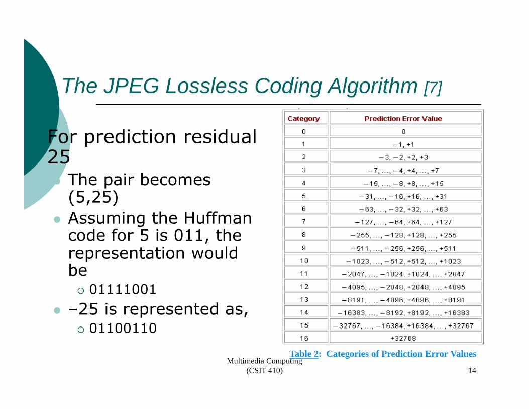
For prediction residual 25
The pair becomes The pair becomes (5,25)Assuming the Huffman
d f 5 i 011 th code for 5 is 011, the representation would be
01111001–25 is represented as,
01100110
Multimedia Computing (CSIT 410)
Table 2: Categories of Prediction Error Values
14
The JPEG Lossless Coding Algorithm [8]
So, Why not using Huffman code Just f th l t f di ti for the complete range of prediction residuals?
Huffman table with 216 entries for all the Huffman table with 216 entries for all the 216 possible symbols of prediction residuals would be almost impossible to work with.
Multimedia Computing (CSIT 410) 15
Baseline JPEG Compression
D fi d f ti t i ith Defined for continuous tone images with 1 to 4 components
Grayscale image consists only one Grayscale image consists only one componentColor image may have up to 4 componentsO l 8 bit ll d f h tOnly 8 bits allowed for each component
Good compression relies on exploiting Good compression relies on exploiting the inter-component correlation between the R, G, B components
Multimedia Computing (CSIT 410) 16
Baseline JPEG Compression [2]
I i R G B t i Image in R,G B components is converted into Luminance-Chrominance components (they are Chrominance components (they are more decorrelated than R,G,B components)
Ch i C f h Chrominance Components are further subsampled
Multimedia Computing (CSIT 410) 17
Baseline JPEG Compression [3]Baseline JPEG Compression [3]COLOR SPACE CONVERSIONS
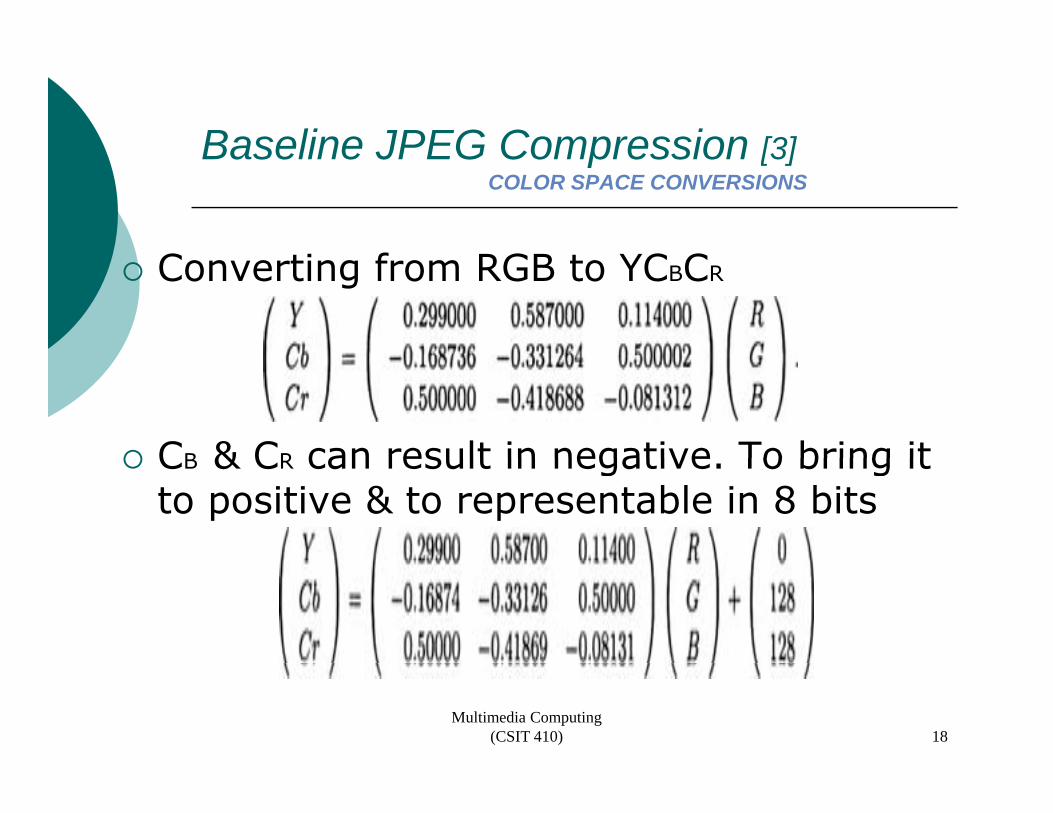
fConverting from RGB to YCBCR
CB & CR can result in negative To bring it CB & CR can result in negative. To bring it to positive & to representable in 8 bits
Multimedia Computing (CSIT 410) 18
Baseline JPEG Compression [4]Baseline JPEG Compression [4]COLOR SPACE CONVERSIONS
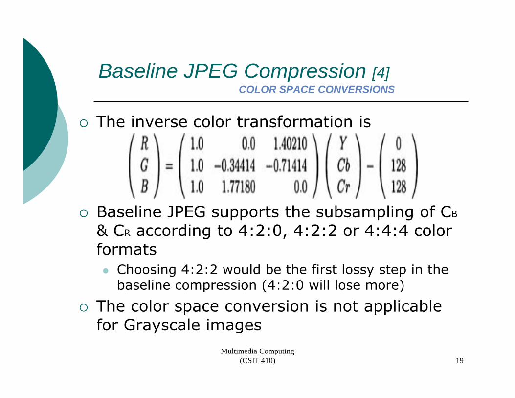
The inverse color transformation is The inverse color transformation is
Baseline JPEG supports the subsampling of CB
d l& CR according to 4:2:0, 4:2:2 or 4:4:4 color formats
Choosing 4:2:2 would be the first lossy step in the g y pbaseline compression (4:2:0 will lose more)
The color space conversion is not applicable for Grayscale imagesfor Grayscale images
Multimedia Computing (CSIT 410) 19
Baseline JPEG Compression [5]Baseline JPEG Compression [5]SOURCE IMAGE DATA ARRANGEMENT
Dimension of each component Y, Cb and CrDimension of each component Y, Cb and Crcould be different, due to subsamplingEach component is divided into 8 x 8 non ac co po e t s d ded to 8 8 ooverlapping blocksIn non interleaved scan, each data blocks ,are coded from left to right & top to bottomIn Interleaved scan, Minimum coded Unit(MCU) consists of data blocks from all the th tthree components
Multimedia Computing (CSIT 410) 20
Baseline JPEG Compression [6]Baseline JPEG Compression [6]SOURCE IMAGE DATA ARRANGEMENT
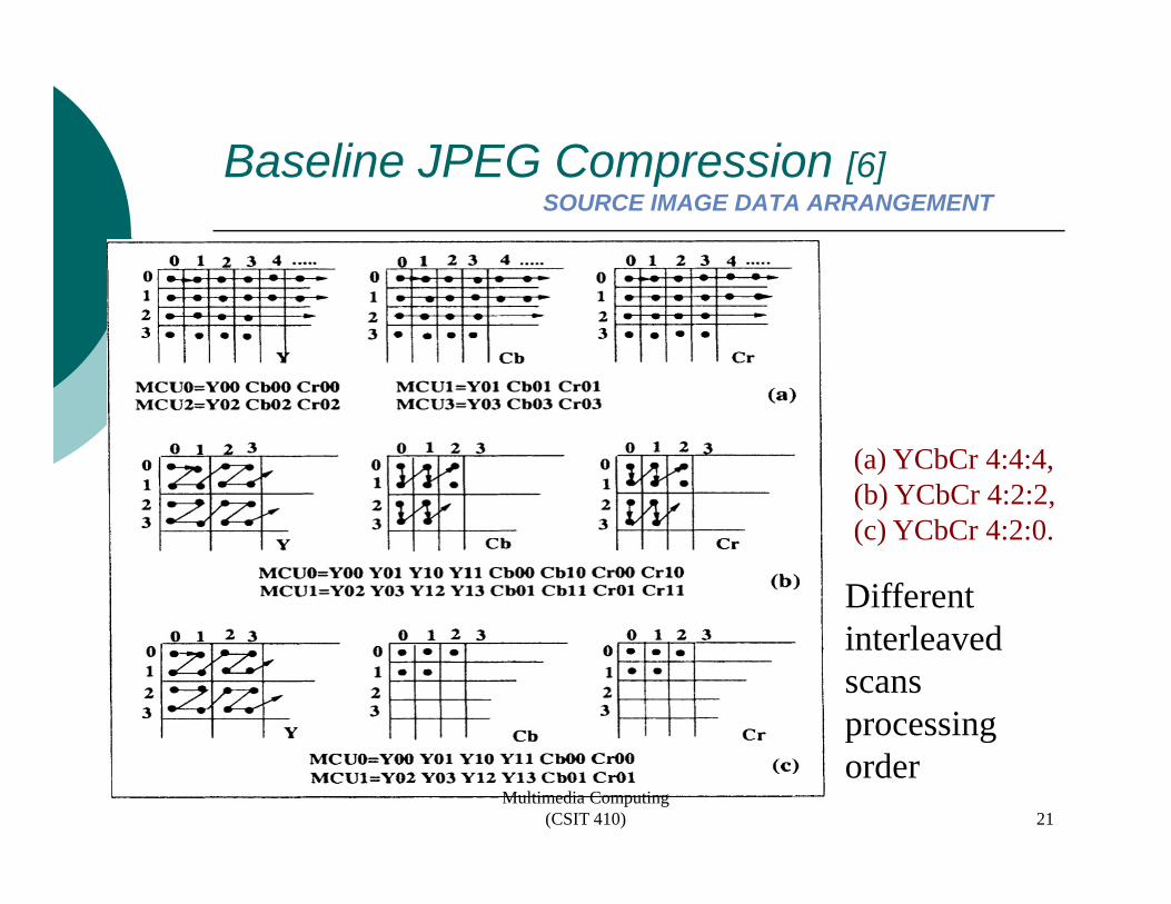
(a) YCbCr 4:4:4, (b) YCbCr 4:2:2, ( )(c) YCbCr 4:2:0.
Different interleaved scans processing
Multimedia Computing (CSIT 410) 21
p gorder
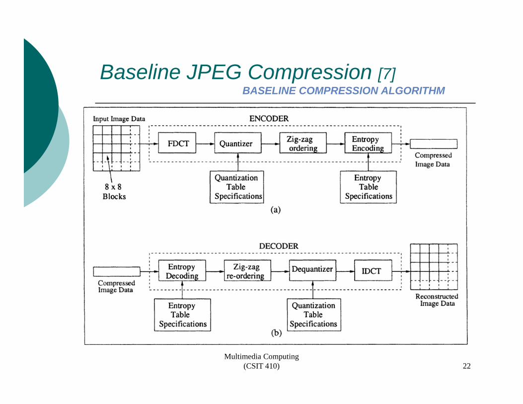
Baseline JPEG Compression [7]Baseline JPEG Compression [7]BASELINE COMPRESSION ALGORITHM
Multimedia Computing (CSIT 410) 22
Baseline JPEG Compression [8]Baseline JPEG Compression [8]BASELINE COMPRESSION ALGORITHM
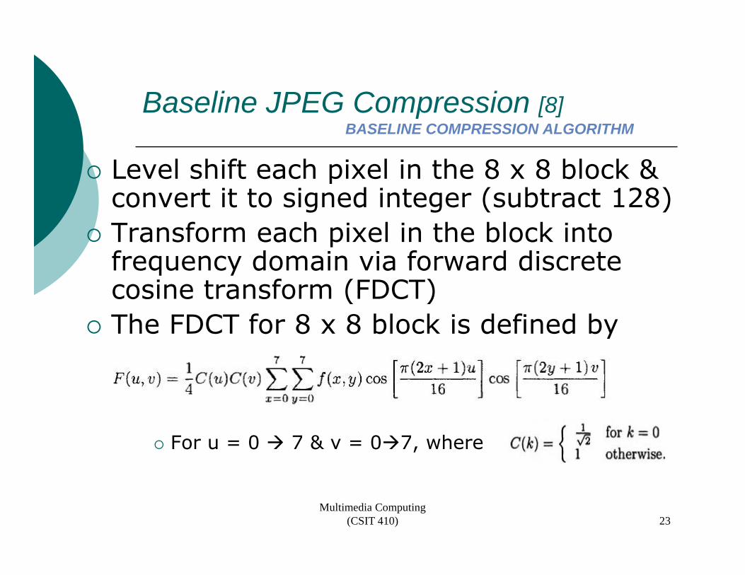
Level shift each pixel in the 8 x 8 block & e e s t eac p e t e 8 8 b oc &convert it to signed integer (subtract 128)Transform each pixel in the block into f d i i f d di frequency domain via forward discrete cosine transform (FDCT)The FDCT for 8 x 8 block is defined byThe FDCT for 8 x 8 block is defined by
For u = 0 7 & v = 0 7, where
Multimedia Computing (CSIT 410) 23
Baseline JPEG Compression [9]Baseline JPEG Compression [9]CODING DCT COEFFICIENTS
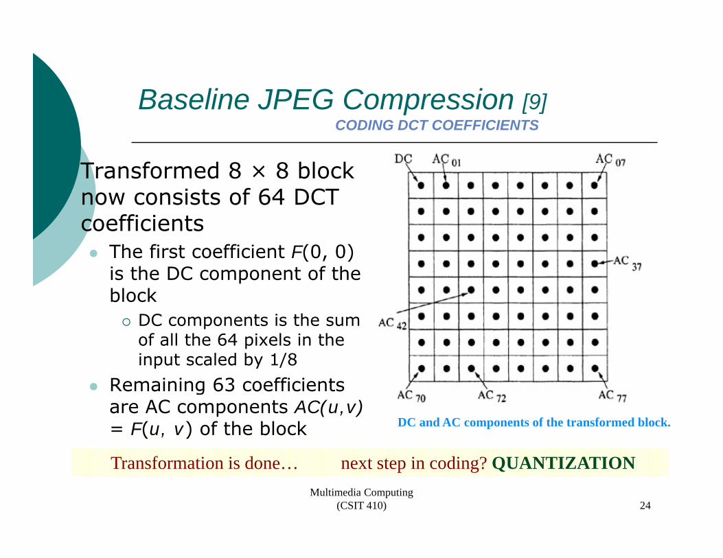
Transformed 8 × 8 block Transformed 8 × 8 block now consists of 64 DCT coefficients
The first coefficient F(0, 0) is the DC component of the block
DC t i th DC components is the sum of all the 64 pixels in the input scaled by 1/8
Remaining 63 coefficients Remaining 63 coefficients are AC components AC(u,v)= F(u, v) of the block DC and AC components of the transformed block.
Multimedia Computing (CSIT 410)
Transformation is done… next step in coding? QUANTIZATION
24
Baseline JPEG Compression [10]Baseline JPEG Compression [10]CODING DCT COEFFICIENTS
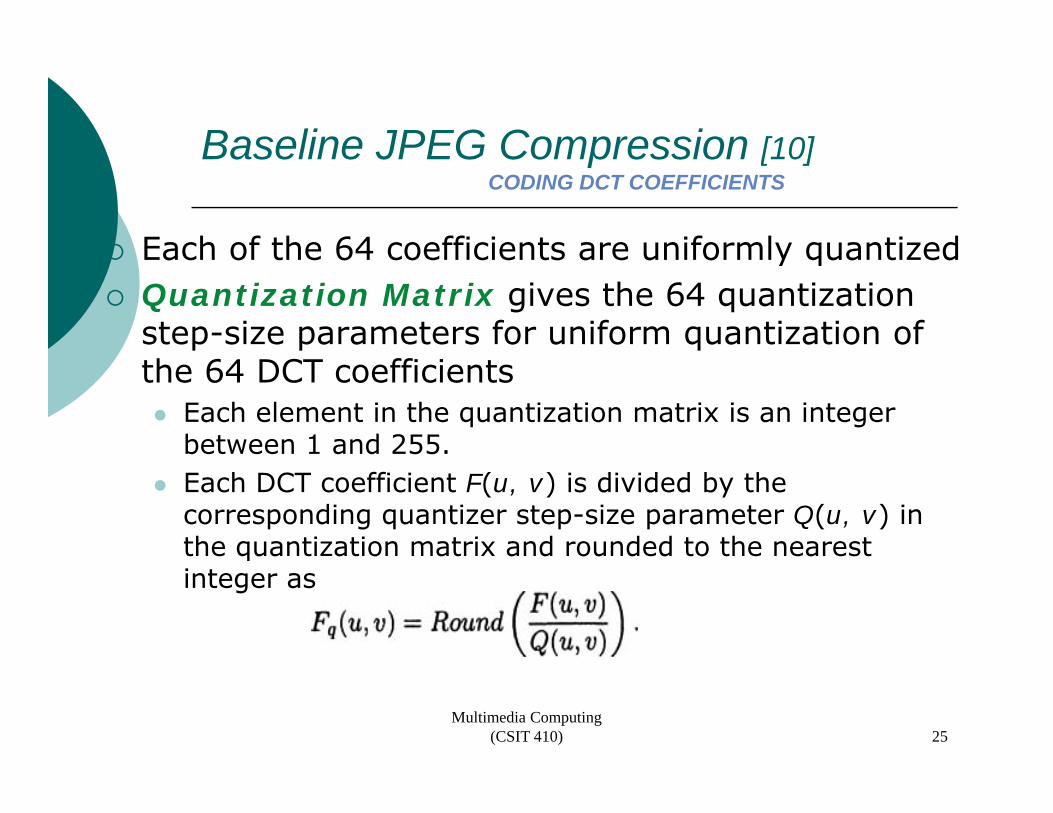
Each of the 64 coefficients are uniformly quantizedEach of the 64 coefficients are uniformly quantizedQuantization Matrix gives the 64 quantization step-size parameters for uniform quantization of the 64 DCT coefficients
Each element in the quantization matrix is an integer between 1 and 255. Each DCT coefficient F(u, v) is divided by the corresponding quantizer step-size parameter Q(u, v) in the quantization matrix and rounded to the nearest qinteger as
Multimedia Computing (CSIT 410) 25
Baseline JPEG Compression [11]Baseline JPEG Compression [11]CODING DCT COEFFICIENTS
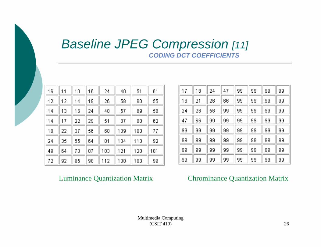
Luminance Quantization Matrix Chrominance Quantization Matrix
Multimedia Computing (CSIT 410) 26
Baseline JPEG Compression [12]Baseline JPEG Compression [12]CODING DCT COEFFICIENTS
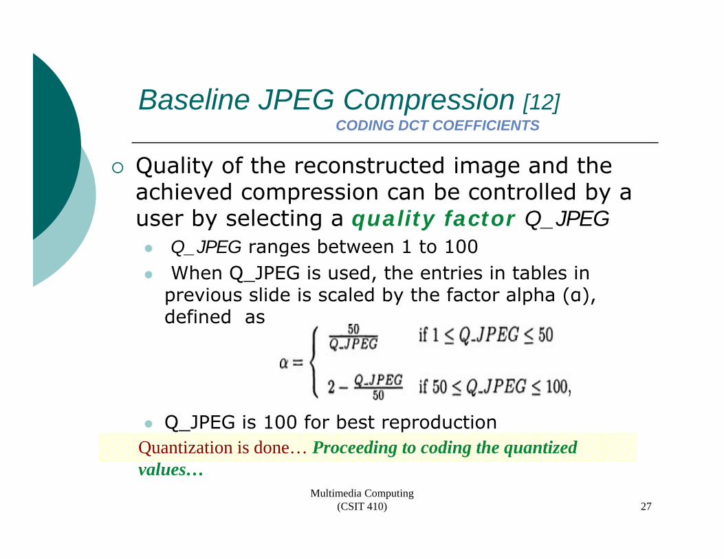
Quality of the reconstructed image and the Q y gachieved compression can be controlled by a user by selecting a quality factor Q_JPEG
Q JPEG ranges between 1 to 100Q_JPEG ranges between 1 to 100When Q_JPEG is used, the entries in tables in previous slide is scaled by the factor alpha (α), defined asdefined as
Q_JPEG is 100 for best reproductionQuantization is done… Proceeding to coding the quantized
Multimedia Computing (CSIT 410)
Q g g qvalues…
27
Baseline JPEG Compression [13]Baseline JPEG Compression [13]CODING DCT COEFFICIENTS
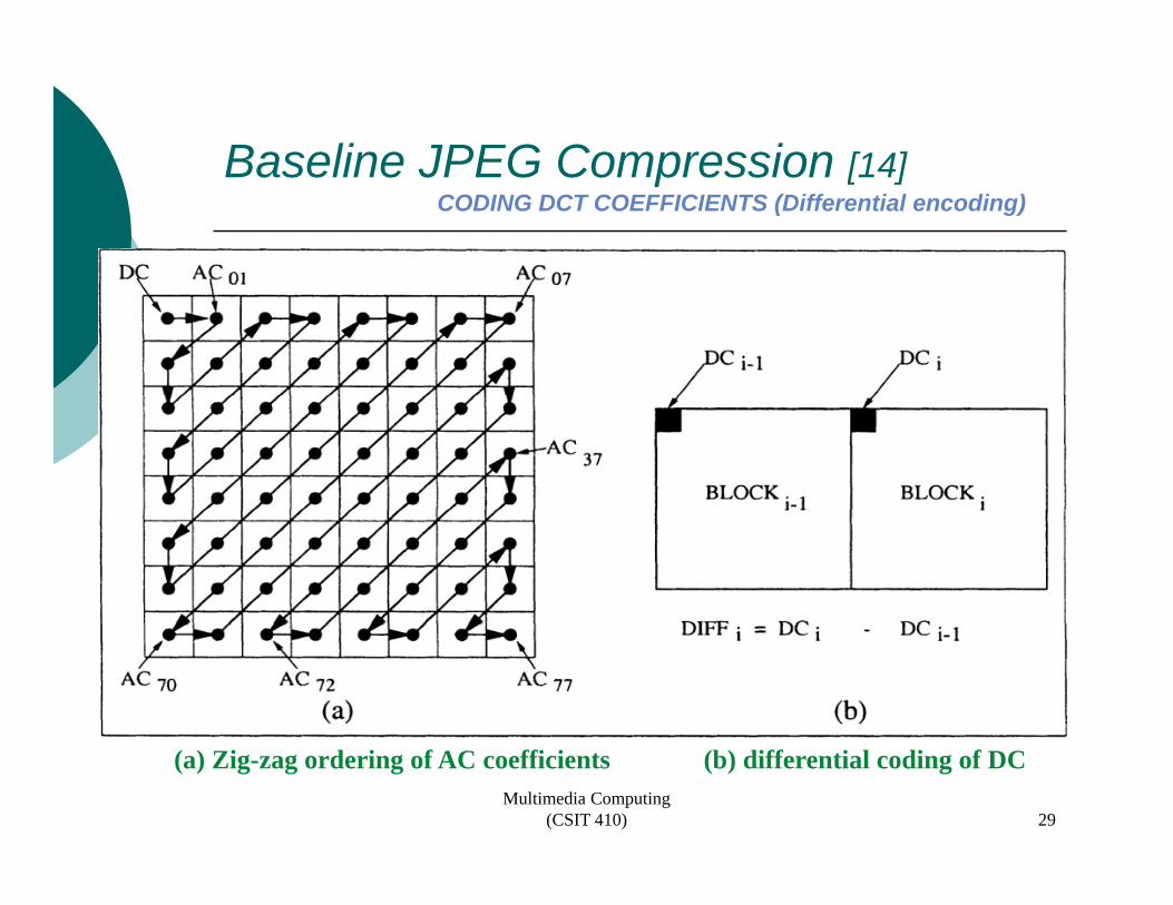
Quantized DC coefficient is encoded by Quantized DC coefficient is encoded by differential encoding
DC coefficient DCi of the current block is subtracted by the DC coefficient Dc of the previous blockby the DC coefficient Dci-1 of the previous blockThe difference DIFF = DCi − DCi−1 is encoded
Encoding AC Componentsg pOnly the nonzero coefficients are encoded by an efficient manner such that the runs of zeros preceding a nonzero value are embedded into the p gencoding.Irregular ordering of the AC coefficients is called zig-zag orderingg g
Multimedia Computing (CSIT 410) 28
Baseline JPEG Compression [14]Baseline JPEG Compression [14]CODING DCT COEFFICIENTS (Differential encoding)
Multimedia Computing (CSIT 410)
(a) Zig-zag ordering of AC coefficients (b) differential coding of DC
29
Baseline JPEG Compression [15]Baseline JPEG Compression [15]CODING DCT COEFFICIENTS
h fThe zig-zag sequence of AC components is broken into a number of runs of zeros ending in a nonzero coefficientending in a nonzero coefficientFor 8-bit images in baseline JPEG, the DCT coefficients fall in the range DCT coefficients fall in the range [−1023, +1023]
Differential values of DC fall in the range e e t a a ues o C a t e a ge[−2047, +2047]
Multimedia Computing (CSIT 410) 30
Baseline JPEG Compression [16]Baseline JPEG Compression [16]CODING DCT COEFFICIENTS
This sequence of AC coefficients is This sequence of AC coefficients is mapped into an intermediate sequence of a combination of two symbols, symbol1, symbol2symbol2
symbol1 is represented by a pair (RUNLENGTH, CATEGORY)
RUNLENGTH is the number of consecutive zeros RUNLENGTH is the number of consecutive zeros preceding the nonzero AC coefficient being encodedCATEGORY is the number of bits to represent the VLI code of this nonzero AC coefficient
symbol2 is a single piece of information designated (AMPLITUDE) that is encoded by the VLI code of the nonzero AC coefficient.
Multimedia Computing (CSIT 410) 31
Baseline JPEG Compression [17]Baseline JPEG Compression [17]CODING DCT COEFFICIENTS
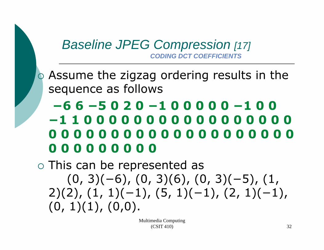
Assume the zigzag ordering results in the Assume the zigzag ordering results in the sequence as follows−6 6 −5 0 2 0 −1 0 0 0 0 0 −1 0 0 6 6 5 0 2 0 1 0 0 0 0 0 1 0 0 −1 1 0 0 0 0 0 0 0 0 0 0 0 0 0 0 0 0 0 0 0 0 0 0 0 0 0 0 0 0 0 0 0 0 0 0 0 0 0 0 0 0 0 0 0 0 0 0 This can be represented as
(0, 3)(−6), (0, 3)(6), (0, 3)(−5), (1, 2)(2), (1, 1)(−1), (5, 1)(−1), (2, 1)(−1), (0 1)(1) (0 0) (0, 1)(1), (0,0).
Multimedia Computing (CSIT 410) 32
Baseline JPEG Compression [18]Baseline JPEG Compression [18]CODING DCT COEFFICIENTS
Two special symbols in encoding the zig-zago spec a sy bo s e cod g t e g agsequence of AC coefficients
(0,0) referred to as EOB (end-of-block), to indicate that the remaining elements in the zig-zag block are that the remaining elements in the zig-zag block are zeros(15, 0) referred to as ZRL (zero-run-length) to indicate a run of 16 zerosindicate a run of 16 zeros
Maximum length of a run of zeros allowed in baseline JPEG is 16
Runs of more than 16 zeros should be broken into the number of runs of zeros of length 16.
Example : 57 zeros before a nonzero coefficient,−29.p ,Represented by (15, 0) (15, 0) (15, 0), (9, 5)(−29)
Multimedia Computing (CSIT 410) 33
Baseline JPEG Compression [19]Baseline JPEG Compression [19]EXAMPLE
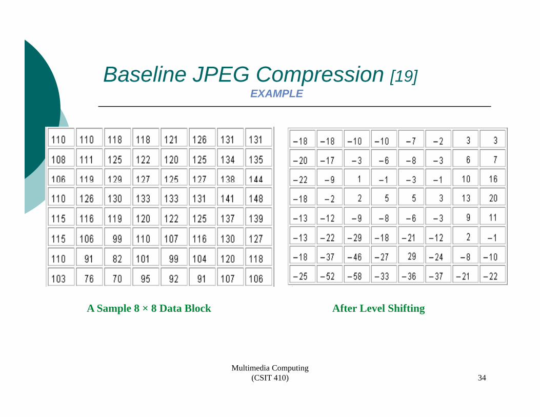
A Sample 8 × 8 Data Block After Level Shifting
Multimedia Computing (CSIT 410) 34
Baseline JPEG Compression [20]Baseline JPEG Compression [20]EXAMPLE
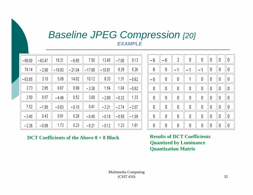
DCT Coefficients of the Above 8 × 8 Block Results of DCT Coefficients Quantized by Luminance Quantization Matrix
Multimedia Computing (CSIT 410) 35
Baseline JPEG Compression [21]Baseline JPEG Compression [21]EXAMPLE
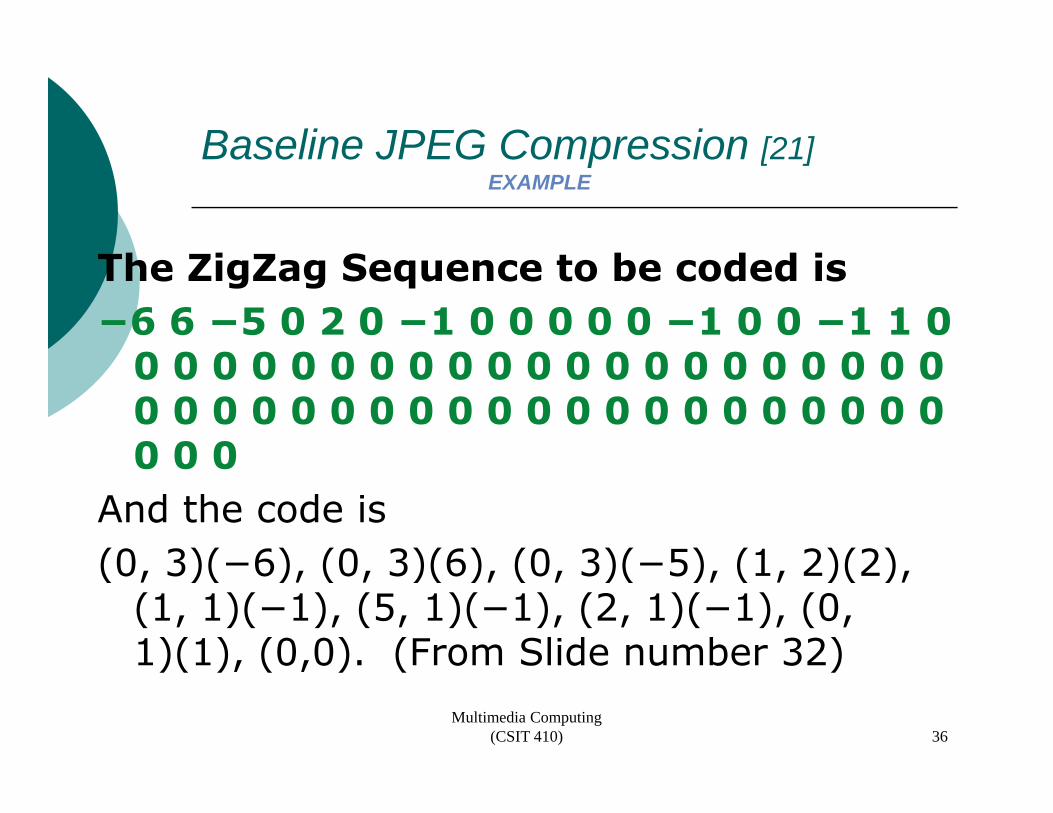
h i b d d iThe ZigZag Sequence to be coded is−6 6 −5 0 2 0 −1 0 0 0 0 0 −1 0 0 −1 1 0
0 0 0 0 0 0 0 0 0 0 0 0 0 0 0 0 0 0 0 0 0 0 0 0 0 0 0 0 0 0 0 0 0 0 0 0 0 0 0 0 0 0 0 0 0 0 0 0 0 0 0 0 0 0 0 0 0 0 0 0 0 0 0 0 0 0 0 0 0
And the code is(0 3)( 6) (0 3)(6) (0 3)( 5) (1 2)(2) (0, 3)(−6), (0, 3)(6), (0, 3)(−5), (1, 2)(2),
(1, 1)(−1), (5, 1)(−1), (2, 1)(−1), (0, 1)(1), (0,0). (From Slide number 32)1)(1), (0,0). (From Slide number 32)
Multimedia Computing (CSIT 410) 36
Baseline JPEG Compression [22]Baseline JPEG Compression [22]EXAMPLE
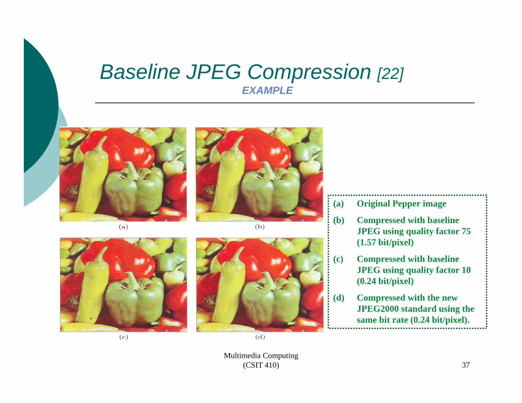
(a) Original Pepper image
(b) Compressed with baseline JPEG using quality factor 75 (1.57 bit/pixel)
(c) Compressed with baseline JPEG using quality factor 10 (0 24 i / i )(0.24 bit/pixel)
(d) Compressed with the new JPEG2000 standard using the same bit rate (0.24 bit/pixel).
Multimedia Computing (CSIT 410) 37
Progressive DCT-Based ModeThe image is coded sequentially in multiple scang q y p
Need to wait till the decoding is over to view the image in sequential mode
Transmit a coarser version of the image in the first gscan and then progressively improve the reconstructed quality at the receiver by transmitting more compressed bits in successive scansp
Complete the computation of DCT coefficients before the start of entropy codingPerform selective encoding of the DCT coefficients & gtransmitTwo methods
spectral selection and successive approximation
Multimedia Computing (CSIT 410) 38
Progressive DCT-Based Mode[2]Progressive DCT Based Mode[2]PROGRESSIVE CODING SUCESSIVE APPROXIMATION
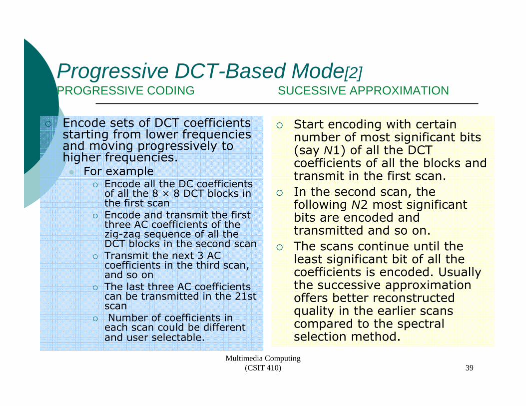
Encode sets of DCT coefficients Start encoding with certain Encode sets of DCT coefficients starting from lower frequencies and moving progressively to higher frequencies.
For example
Start encoding with certain number of most significant bits (say N1) of all the DCT coefficients of all the blocks and transmit in the first scan
Encode all the DC coefficients of all the 8 × 8 DCT blocks in the first scanEncode and transmit the first three AC coefficients of the
transmit in the first scan. In the second scan, the following N2 most significant bits are encoded and transmitted and so onzig-zag sequence of all the
DCT blocks in the second scanTransmit the next 3 AC coefficients in the third scan, and so on
transmitted and so on.The scans continue until the least significant bit of all the coefficients is encoded. Usually
The last three AC coefficients can be transmitted in the 21st scanNumber of coefficients in each scan could be different
the successive approximation offers better reconstructed quality in the earlier scans compared to the spectral
and user selectable. selection method. Multimedia Computing
(CSIT 410) 39
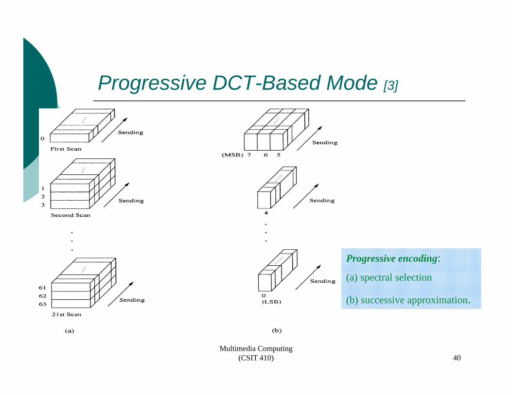
Progressive DCT-Based Mode [3]
Progressive encoding:(a) spectral selection
(b) successive approximation.
Multimedia Computing (CSIT 410) 40
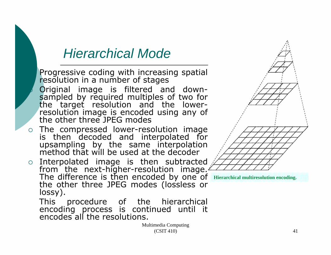
Hierarchical ModeProgressive coding with increasing spatialresolution in a number of stagesresolution in a number of stagesOriginal image is filtered and down-sampled by required multiples of two forthe target resolution and the lower-resolution image is encoded using any ofresolution image is encoded using any ofthe other three JPEG modesThe compressed lower-resolution imageis then decoded and interpolated forupsampling by the same interpolationupsampling by the same interpolationmethod that will be used at the decoderInterpolated image is then subtractedfrom the next-higher-resolution image.The difference is then encoded by one of Hi hi l l i l i diThe difference is then encoded by one ofthe other three JPEG modes (lossless orlossy).This procedure of the hierarchicalencoding process is continued until it
Hierarchical multiresolution encoding.
encoding process is continued until itencodes all the resolutions.
Multimedia Computing (CSIT 410) 41

Reference
1 Chapter 91. Chapter 92. Chapter 3 of JPEG2000 Standard for Image Compression: Concepts, Algorithms and VLSI Architectures by Tinku Acharya and Ping-Sing Tsai , John Wiley & Sons
See Blackboard, Course Materials
Multimedia Computing (CSIT 410) 42
Top Related