


γλώσσες
Σελίδες
Νομικός

Page 1 / 14 Project
LRFD Design Methodology Project #
08110.00 Date
9/24/09
13478 Chandler Road, Omaha, Nebraska 68138 402/556-2171 (Fax 402/556-7831)
GRAVITY WALL LRFD DESIGN METHODOLOGY STONE STRONG PRECAST MODULAR BLOCK
Evaluate according to industry practice following AASHTO analytical techniques – refer to: AASHTO LRFD Bridge Design Specifications, 4th Edition 2007 Additional analytical methods and theories are taken from previous AASHTO specifications and other FHWA guidelines – refer to: AASHTO Standard Specifications for Highway Bridges 2002, 17th Addition Mechanically Stabilized Earth Walls and Reinforced Slopes design and Construction
Guidelines, NHI-00-043 Properties of Soil/Aggregate soil and material properties should be determined for the specific materials to be used.
unit fill - γa = 110 pcf (max, see AASHTO 2002 5.9.2) & φu
leveling base – aggregate base typical γb & φb (or concrete base may be substituted)
retained soil - γ & φ by site conditions
foundation soil - γ φ & c by site conditions
interface angle - δ = ½ φ (see AASHTO LRFD Table C3.11.5.9-1) Geometric Properties
Effective weight of unit block weight 24 SF unit – 750 lb/ft of wall 6 SF unit – 450 lb/ft of wall weight of aggregate 24 SF unit – 596 lb/ft of wall 6 SF unit – 296 lb/ft of wall
Only 80% of the weight of aggregate and soil is included in the overturning calculations, W’ (see AASHTO LRFD 11.11.4.4).
Page 2 / 14 Project
LRFD Design Methodology Project #
08110.00 Date
9/24/09
13478 Chandler Road, Omaha, Nebraska 68138 402/556-2171 (Fax 402/556-7831)
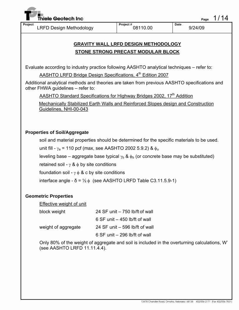
Typical gravity wall configuration:
β
δ−ω
δ−ω
ω
Page 3 / 14 Project
LRFD Design Methodology Project #
08110.00 Date
9/24/09
13478 Chandler Road, Omaha, Nebraska 68138 402/556-2171 (Fax 402/556-7831)
Unit Width/Center of Mass The nominal unit width is 44 inches for both 24 SF and 6 SF blocks. The combined center of mass of the concrete block and the unit fill is at 22.7 inches from the face.
wu = 3.67 ft xu = 1.89 ft
Wall batter The wall system is based around the 24 SF block that is 36 inches of height. The next block atop a 24 SF block will batter back 4 inches. The 6 SF block is 18 inches tall, and the next block atop a 6 SF block will batter 2 inches.
4 in. setback per 24 SF block (36 in. tall) 2 in. setback per 6 SF block (18 in. tall)
ω = tan-1(4/36) = 6.34° ω’ = tan-1(4/36) = 6.34° (batter along back face matches the batter along the front)
Base Thickness/Embedment The type and thickness of wall base or leveling pad and depth of embedment can vary by site requirements. A granular base with a thickness of 9 inches is commonly used, but the thickness can be adjusted to reduce the contact pressure. A concrete leveling pad or footing can also be used. The required embedment to the top of the base is related to the exposed height of the wall and by the slope at the toe, as well as other factors. The required embedment can be calculated for slopes steeper than 6H:1V using the following equation (see AASHTO LRFD Table C11.10.2.2-1):
he = H’/(20*S/6) where S is the run of the toe slope per unit fall and H’ is the exposed height
A minimum embedment of 12 inches for level toe and 24 inches for toe slopes of 4H:1V or steeper is recommended for highway applications (AASHTO LRFD C.11.10.2.2)
Page 4 / 14 Project
LRFD Design Methodology Project #
08110.00 Date
9/24/09
13478 Chandler Road, Omaha, Nebraska 68138 402/556-2171 (Fax 402/556-7831)
Tail Extension Adjustments
The gravity wall capability can be increased by using a precast Mass Extender block (limited to approximately 12 additional inches, for a total block width of 56 inches) or a cast-in-place tail extension (width is not limited – recommend height be at least 2 times the width to provide shear through the tail openings). If tail extensions are used, the following adjustments are made:
Wall batter
Wall batter is recalculated along the back of the wall from the rear of the tail extension to the rear of the top of the wall. Use ω’ in Coulomb equation and earth pressure component calculations. To calculate ω’ it is necessary to know the effective setback width, ws, which in the horizontal distance between the back edge of the top block and the back edge of the mass extender at the bottom. ws is the batter of the front face minus the length of tail extension, wte. ws is negative when the mass extender projects further than the back of the top block. Knowing this distance and the height of wall:
ω’ = arctan(ws / Hw)
Interface Angle
δ = ¾ φ (see AASHTO LRFD Table C3.11.5.9-1)
Weight of Wall
The weight of the wall includes the contributions of the mass extender and the soil wedge atop the mass extender. A typical concrete unit weight is 145 pcf. Use the soil unit weight for the soil wedge.
Wte = (wte * Hte) * 145 pcf where wte is the width of the tail extension and Hte is the height of the extension (both in ft)
The weight of the soil triangle is calculated using the following equation:
Ws = (H - Hte) * γ * wte/2 Note: The soil wedge is defined by the limit of the tail extension and not by the simplified batter of the back of the wall. The simplified batter is used in the earth pressure analysis. Since the minimum width of the tail extension is typically maintained, it may project beyond the extension at the first course.
Page 5 / 14 Project
LRFD Design Methodology Project #
08110.00 Date
9/24/09
13478 Chandler Road, Omaha, Nebraska 68138 402/556-2171 (Fax 402/556-7831)
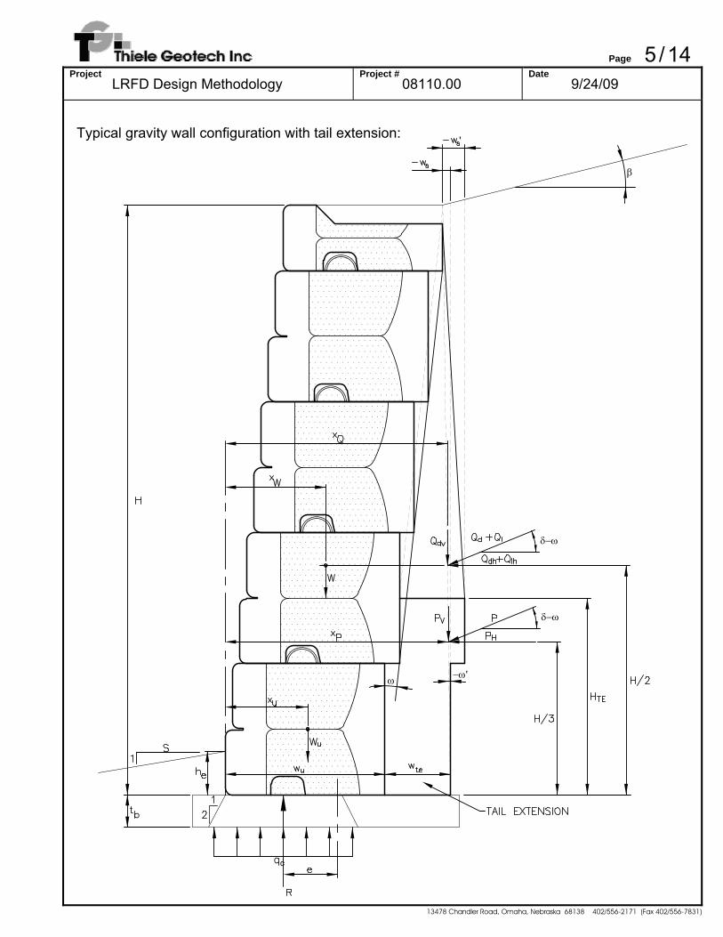
Typical gravity wall configuration with tail extension:
−ω'ω
δ−ω
δ−ω
β
'
Page 6 / 14 Project
LRFD Design Methodology Project #
08110.00 Date
9/24/09
13478 Chandler Road, Omaha, Nebraska 68138 402/556-2171 (Fax 402/556-7831)
Calculate Forces
Coulomb active earth pressure coefficient (see AASHTO LRFD 3.11.5.3)
( )
( ) ( ) ( ) ( )( ) ( )
2
2
2
a
β'cos'cossinsin1'cos'cos
'cosK
⎥⎦
⎤⎢⎣
⎡
+ωδ−ωβ−φδ+φ
+δ−ωω
ω+φ=
Earth load components (see AASHTO LRFD 11.10.5.2)
Vertical Forces:
Pv = 0.5 KaγH2sin(δ - ω') Qdv = KaQ*H*sin(δ - ω’) where Q is the effective surcharge in psf
Horizontal Forces:
Ph = 0.5 KaγH2cos(δ - ω’) Qdh = KaQ*H*cos(δ - ω’) where Q is the effective surcharge in psf Qlh = KaQ*H*cos(δ - ω’) where Q is the effective surcharge in psf Note: Surcharge loads may be divided into dead and live load components. The vertical component of the live load (Qlv) is a stabilizing force and should be neglected as conservative. For the example calculations, the surcharge is treated as a dead load consistent with its use in the seismic calculations.
Resisting forces
Vertical Forces: Wb – Weight of wall units Wte – Weight of concrete tail extension, if used Wa – Weight of infill aggregate (use 80% aggregate weight for overturning) Ws – Weight of soil atop tail extension (use 80% aggregate weight for overturning)
The center of gravity of the components of the wall can be calculated by laying out the components of the wall and taking a weighted average of their weight and distance from the hinge point of the block (see AASHTO 2002 5.9.2). Alternately, the center of mass can be calculated using the following equations:
Page 7 / 14 Project
LRFD Design Methodology Project #
08110.00 Date
9/24/09
13478 Chandler Road, Omaha, Nebraska 68138 402/556-2171 (Fax 402/556-7831)
The center of mass of the stack of blocks is calculated as: xb = xu + (H - hu)/2 * tan(ω) The center of mass of the soil triangle over the tail is;
xs = wu + (Hte - hu) * tan(ω) + 2 * wte/3 - ws’/3 The center of mass of the tail extension can be calculated with the following equation:
xte = wu + wte/2 This leads to an overall adjusted center of mass of:
xw = [[xu + (H - Hu)/2 * tan(ω)] * (Wb + Wa) + xte * Wte + xs * Ws]/(Wb + Wa + Wte + Ws) Note: the height of unit, hu, is taken as 3 ft. based on the 24 SF unit instead of 1.5 ft. based on the 6 SF unit to produce the more conservative result (units can be stacked with either unit as the bottom course).
The resultants of the earth load components are calculated as follows:
xPv=(H/3)*tan(ω’) + wu + wte
xQdv=(H/2) )*tan(ω’) + wu + wte xPh=H/3 xQdh=H/2 xQlh=H/2
Table of Unfactored Forces & Moments
Force x Moment about toe (lb) (ft) (lb*ft)
Vertical Forces weight of wall Wb + Wa + Wte + Ws xw (Wb + Wa + Wte + Ws) * xw
modified weight Wb + 0.8*Wa + Wte + 0.8*Ws xw (Wb + 0.8*Wa + Wte + 0.8*Ws) * xw
earth pressure Pv xPv Pv*xPv
DL surcharge Qdv xQdv Qdv*xQdv
Horizontal Forces earth pressure Ph xPh Ph*xPh
DL surcharge Qdh xQdh Qdh*xQdh LL surcharge Qlh xQlh Qlh*xQlh
Page 8 / 14 Project
LRFD Design Methodology Project #
08110.00 Date
9/24/09
13478 Chandler Road, Omaha, Nebraska 68138 402/556-2171 (Fax 402/556-7831)
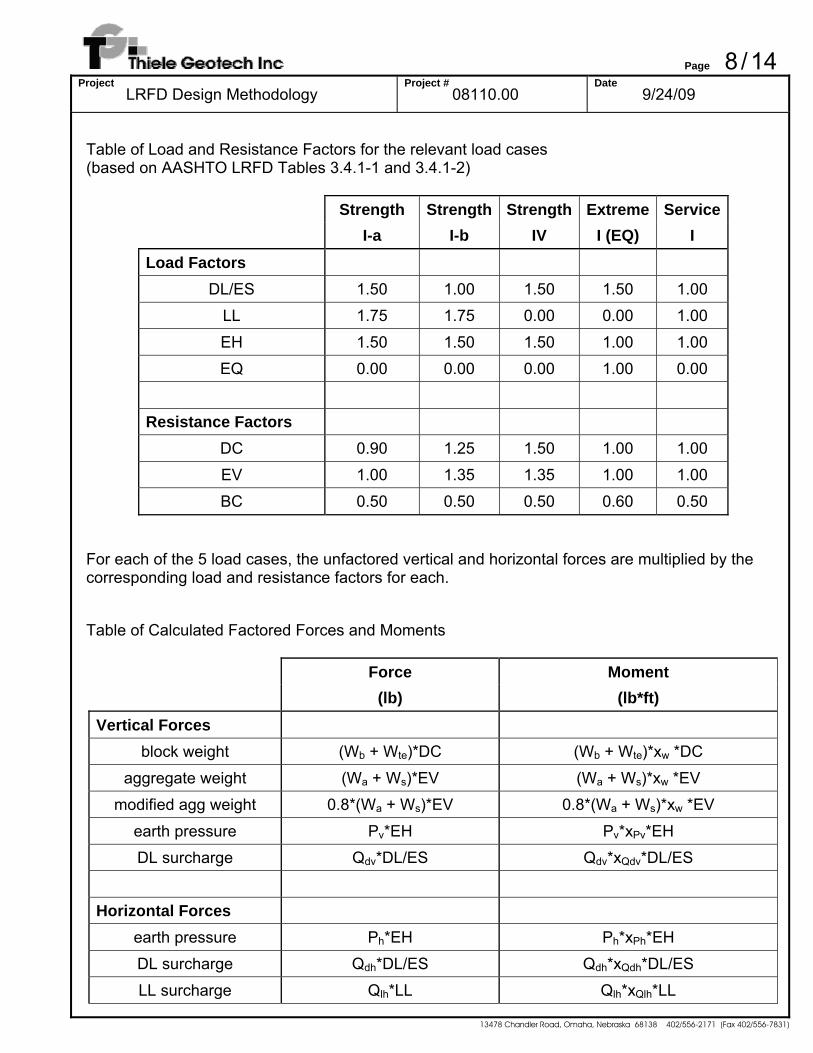
Table of Load and Resistance Factors for the relevant load cases (based on AASHTO LRFD Tables 3.4.1-1 and 3.4.1-2)
Strength Strength Strength Extreme ServiceI-a I-b IV I (EQ) I
Load Factors DL/ES 1.50 1.00 1.50 1.50 1.00
LL 1.75 1.75 0.00 0.00 1.00
EH 1.50 1.50 1.50 1.00 1.00 EQ 0.00 0.00 0.00 1.00 0.00
Resistance Factors DC 0.90 1.25 1.50 1.00 1.00 EV 1.00 1.35 1.35 1.00 1.00
BC 0.50 0.50 0.50 0.60 0.50
For each of the 5 load cases, the unfactored vertical and horizontal forces are multiplied by the corresponding load and resistance factors for each. Table of Calculated Factored Forces and Moments
Force Moment
(lb) (lb*ft) Vertical Forces
block weight (Wb + Wte)*DC (Wb + Wte)*xw *DC
aggregate weight (Wa + Ws)*EV (Wa + Ws)*xw *EV modified agg weight 0.8*(Wa + Ws)*EV 0.8*(Wa + Ws)*xw *EV
earth pressure Pv*EH Pv*xPv*EH DL surcharge Qdv*DL/ES Qdv*xQdv*DL/ES
Horizontal Forces earth pressure Ph*EH Ph*xPh*EH DL surcharge Qdh*DL/ES Qdh*xQdh*DL/ES
LL surcharge Qlh*LL Qlh*xQlh*LL
Page 9 / 14 Project
LRFD Design Methodology Project #
08110.00 Date
9/24/09
13478 Chandler Road, Omaha, Nebraska 68138 402/556-2171 (Fax 402/556-7831)
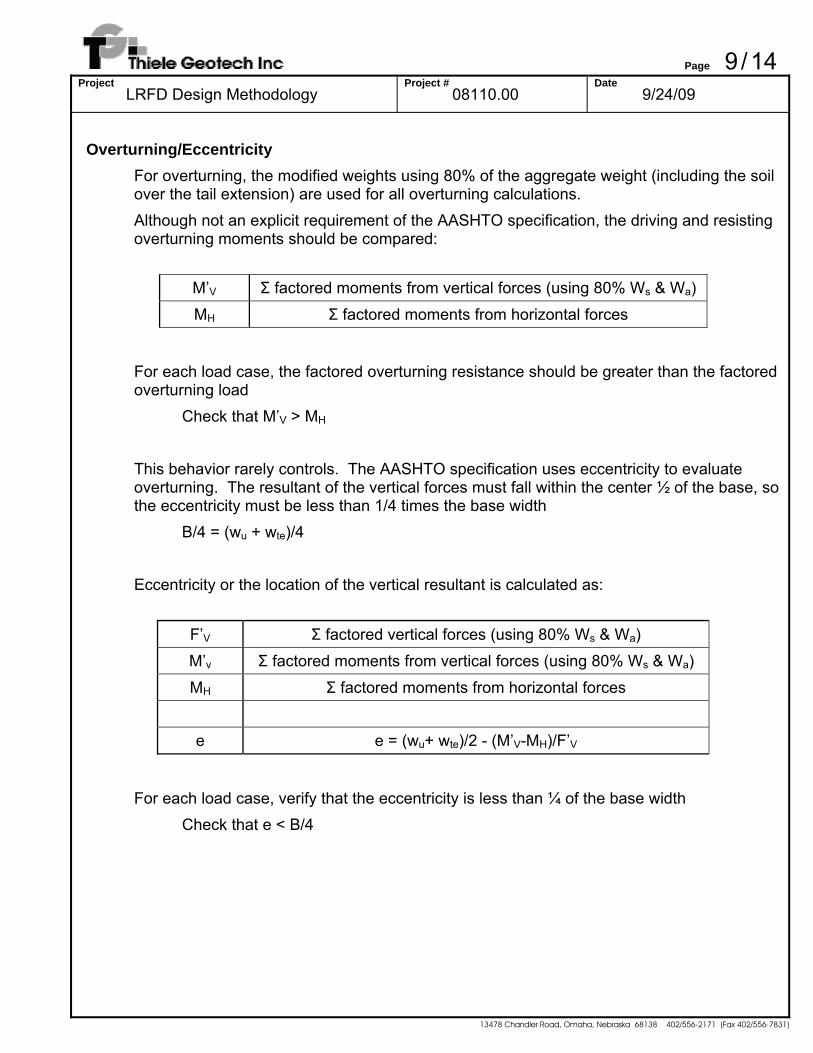
Overturning/Eccentricity
For overturning, the modified weights using 80% of the aggregate weight (including the soil over the tail extension) are used for all overturning calculations. Although not an explicit requirement of the AASHTO specification, the driving and resisting overturning moments should be compared:
M’V Σ factored moments from vertical forces (using 80% Ws & Wa)
MH Σ factored moments from horizontal forces
For each load case, the factored overturning resistance should be greater than the factored overturning load
Check that M’V > MH This behavior rarely controls. The AASHTO specification uses eccentricity to evaluate overturning. The resultant of the vertical forces must fall within the center ½ of the base, so the eccentricity must be less than 1/4 times the base width
B/4 = (wu + wte)/4 Eccentricity or the location of the vertical resultant is calculated as:
F’V Σ factored vertical forces (using 80% Ws & Wa) M’v Σ factored moments from vertical forces (using 80% Ws & Wa)
MH Σ factored moments from horizontal forces
e e = (wu+ wte)/2 - (M’V-MH)/F’V
For each load case, verify that the eccentricity is less than ¼ of the base width
Check that e < B/4
Page 10 / 14 Project
LRFD Design Methodology Project #
08110.00 Date
9/24/09
13478 Chandler Road, Omaha, Nebraska 68138 402/556-2171 (Fax 402/556-7831)
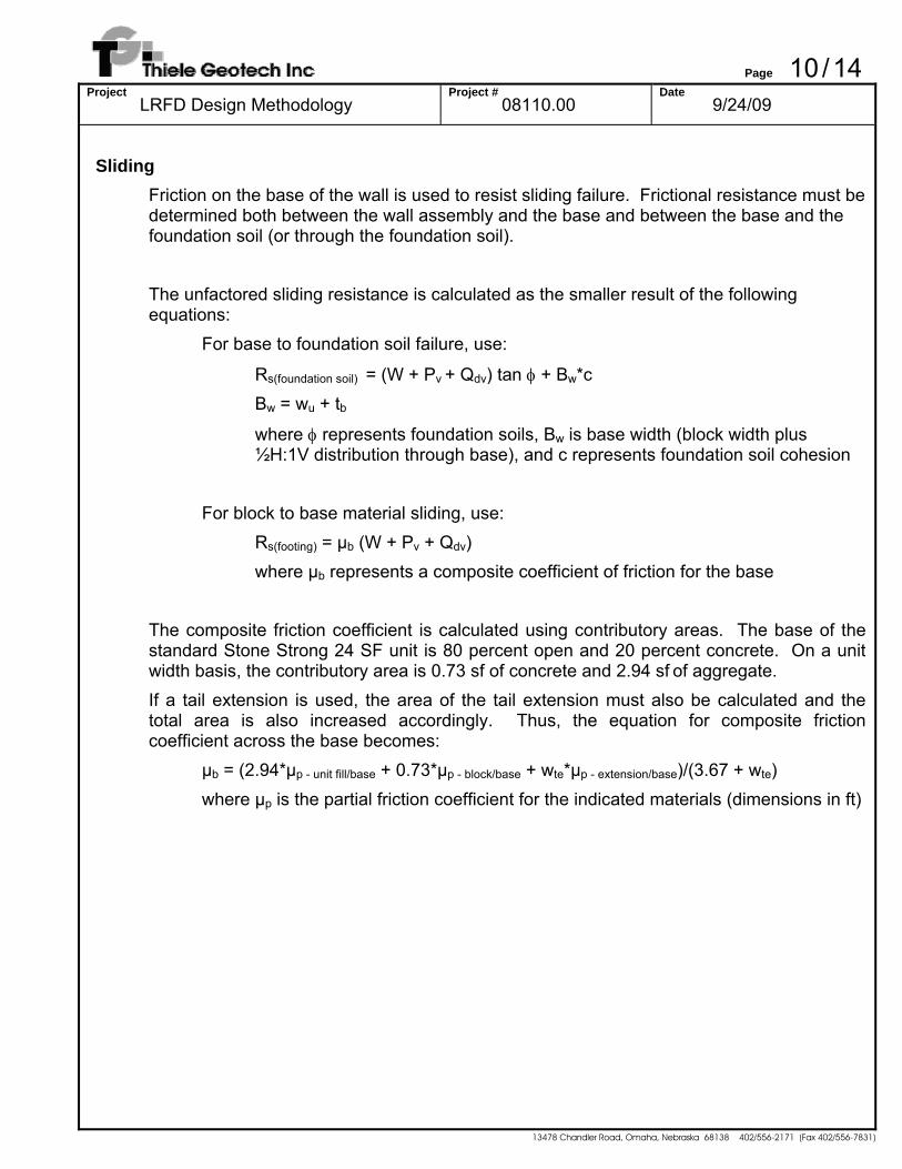
Sliding
Friction on the base of the wall is used to resist sliding failure. Frictional resistance must be determined both between the wall assembly and the base and between the base and the foundation soil (or through the foundation soil). The unfactored sliding resistance is calculated as the smaller result of the following equations:
For base to foundation soil failure, use:
Rs(foundation soil) = (W + Pv + Qdv) tan φ + Bw*c Bw = wu + tb
where φ represents foundation soils, Bw is base width (block width plus ½H:1V distribution through base), and c represents foundation soil cohesion
For block to base material sliding, use:
Rs(footing) = μb (W + Pv + Qdv) where μb represents a composite coefficient of friction for the base
The composite friction coefficient is calculated using contributory areas. The base of the standard Stone Strong 24 SF unit is 80 percent open and 20 percent concrete. On a unit width basis, the contributory area is 0.73 sf of concrete and 2.94 sf of aggregate. If a tail extension is used, the area of the tail extension must also be calculated and the total area is also increased accordingly. Thus, the equation for composite friction coefficient across the base becomes: μb = (2.94*μp - unit fill/base + 0.73*μp - block/base + wte*μp - extension/base)/(3.67 + wte) where μp is the partial friction coefficient for the indicated materials (dimensions in ft)
Page 11 / 14 Project
LRFD Design Methodology Project #
08110.00 Date
9/24/09
13478 Chandler Road, Omaha, Nebraska 68138 402/556-2171 (Fax 402/556-7831)
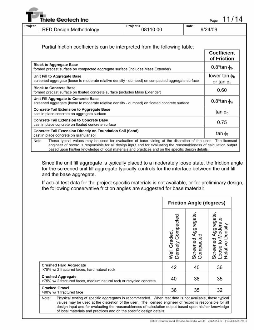
Partial friction coefficients can be interpreted from the following table:
Coefficient of Friction
Block to Aggregate Base formed precast surface on compacted aggregate surface (includes Mass Extender) 0.8*tan φb
Unit Fill to Aggregate Base screened aggregate (loose to moderate relative density - dumped) on compacted aggregate surface
lower tan φb or tan φu
Block to Concrete Base formed precast surface on floated concrete surface (includes Mass Extender) 0.60 Unit Fill Aggregate to Concrete Base screened aggregate (loose to moderate relative density - dumped) on floated concrete surface 0.8*tan φu Concrete Tail Extension to Aggregate Base cast in place concrete on aggregate surface tan φb Concrete Tail Extension to Concrete Base cast in place concrete on floated concrete surface 0.75 Concrete Tail Extension Directly on Foundation Soil (Sand) cast in place concrete on granular soil tan φf Note: These typical values may be used for evaluation of base sliding at the discretion of the user. The licensed
engineer of record is responsible for all design input and for evaluating the reasonableness of calculation output based upon his/her knowledge of local materials and practices and on the specific design details.
Since the unit fill aggregate is typically placed to a moderately loose state, the friction angle for the screened unit fill aggregate typically controls for the interface between the unit fill and the base aggregate. If actual test data for the project specific materials is not available, or for preliminary design, the following conservative friction angles are suggested for base material: Friction Angle (degrees)
Wel
l Gra
ded,
Den
sely
Com
pact
ed
Scr
eene
d A
ggre
gate
,
Com
pact
ed
Scr
eene
d A
ggre
gate
,
Loos
e to
Mod
erat
e R
elat
ive
Den
sity
Crushed Hard Aggregate >75% w/ 2 fractured faces, hard natural rock 42 40 36
Crushed Aggregate >75% w/ 2 fractured faces, medium natural rock or recycled concrete 40 38 35
Cracked Gravel >90% w/ 1 fractured face 36 35 32 Note: Physical testing of specific aggregates is recommended. When test data is not available, these typical
values may be used at the discretion of the user. The licensed engineer of record is responsible for all design input and for evaluating the reasonableness of calculation output based upon his/her knowledge of local materials and practices and on the specific design details.
Page 12 / 14 Project
LRFD Design Methodology Project #
08110.00 Date
9/24/09
13478 Chandler Road, Omaha, Nebraska 68138 402/556-2171 (Fax 402/556-7831)
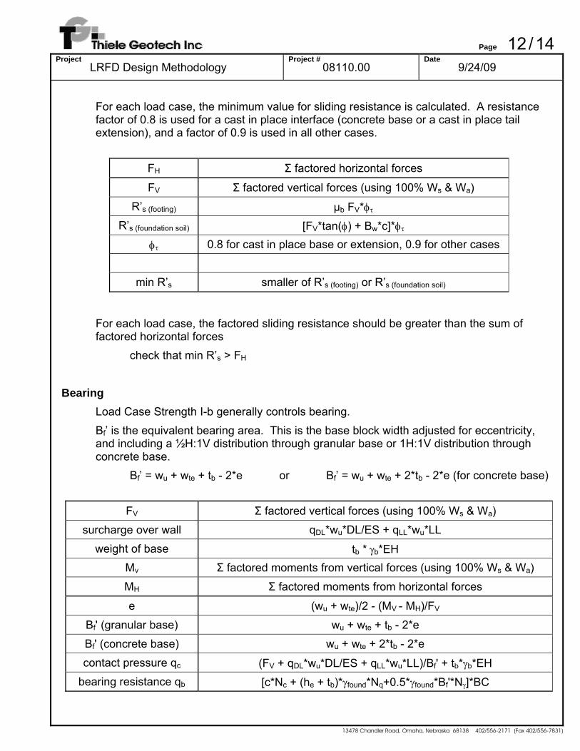
For each load case, the minimum value for sliding resistance is calculated. A resistance factor of 0.8 is used for a cast in place interface (concrete base or a cast in place tail extension), and a factor of 0.9 is used in all other cases.
FH Σ factored horizontal forces
FV Σ factored vertical forces (using 100% Ws & Wa) R’s (footing) μb FV*φτ
R’s (foundation soil) [FV*tan(φ) + Bw*c]*φτ
φτ 0.8 for cast in place base or extension, 0.9 for other cases
min R’s smaller of R’s (footing) or R’s (foundation soil)
For each load case, the factored sliding resistance should be greater than the sum of factored horizontal forces
check that min R’s > FH Bearing
Load Case Strength I-b generally controls bearing. Bf’ is the equivalent bearing area. This is the base block width adjusted for eccentricity, and including a ½H:1V distribution through granular base or 1H:1V distribution through concrete base.
Bf’ = wu + wte + tb - 2*e or Bf’ = wu + wte + 2*tb - 2*e (for concrete base)
FV Σ factored vertical forces (using 100% Ws & Wa) surcharge over wall qDL*wu*DL/ES + qLL*wu*LL
weight of base tb * γb*EH Mv Σ factored moments from vertical forces (using 100% Ws & Wa)
MH Σ factored moments from horizontal forces
e (wu + wte)/2 - (MV - MH)/FV
Bf' (granular base) wu + wte + tb - 2*e Bf' (concrete base) wu + wte + 2*tb - 2*e
contact pressure qc (FV + qDL*wu*DL/ES + qLL*wu*LL)/Bf' + tb*γb*EH bearing resistance qb [c*Nc + (he + tb)*γfound*Nq+0.5*γfound*Bf'*Nγ]*BC
Page 13 / 14 Project
LRFD Design Methodology Project #
08110.00 Date
9/24/09
13478 Chandler Road, Omaha, Nebraska 68138 402/556-2171 (Fax 402/556-7831)
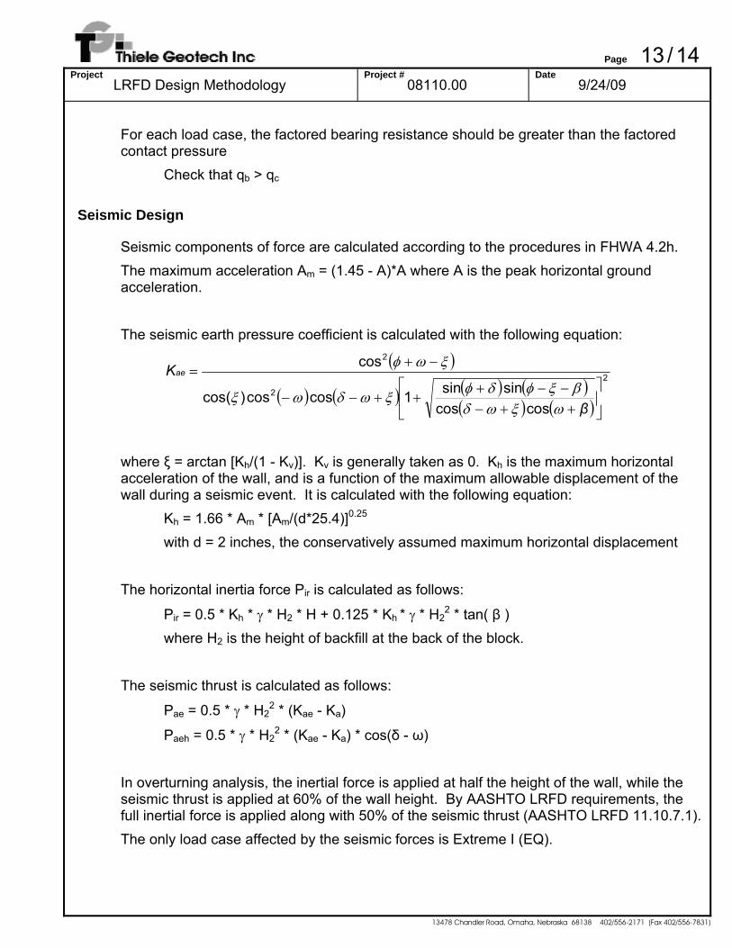
For each load case, the factored bearing resistance should be greater than the factored contact pressure
Check that qb > qc Seismic Design
Seismic components of force are calculated according to the procedures in FHWA 4.2h. The maximum acceleration Am = (1.45 - A)*A where A is the peak horizontal ground acceleration. The seismic earth pressure coefficient is calculated with the following equation:
( )
( ) ( ) ( ) ( )( ) ( )
2
2
2
coscossinsin1coscos)cos(
cos
⎥⎦
⎤⎢⎣
⎡
++−−−+
++−−
−+=
β
Kae
ωξωδβξφδφξωδωξ
ξωφ
where ξ = arctan [Kh/(1 - Kv)]. Kv is generally taken as 0. Kh is the maximum horizontal
acceleration of the wall, and is a function of the maximum allowable displacement of the wall during a seismic event. It is calculated with the following equation:
Kh = 1.66 * Am * [Am/(d*25.4)]0.25 with d = 2 inches, the conservatively assumed maximum horizontal displacement
The horizontal inertia force Pir is calculated as follows:
Pir = 0.5 * Kh * γ * H2 * H + 0.125 * Kh * γ * H22 * tan( β )
where H2 is the height of backfill at the back of the block.
The seismic thrust is calculated as follows:
Pae = 0.5 * γ * H22 * (Kae - Ka)
Paeh = 0.5 * γ * H22 * (Kae - Ka) * cos(δ - ω)
In overturning analysis, the inertial force is applied at half the height of the wall, while the seismic thrust is applied at 60% of the wall height. By AASHTO LRFD requirements, the full inertial force is applied along with 50% of the seismic thrust (AASHTO LRFD 11.10.7.1). The only load case affected by the seismic forces is Extreme I (EQ).
Page 14 / 14 Project
LRFD Design Methodology Project #
08110.00 Date
9/24/09
13478 Chandler Road, Omaha, Nebraska 68138 402/556-2171 (Fax 402/556-7831)
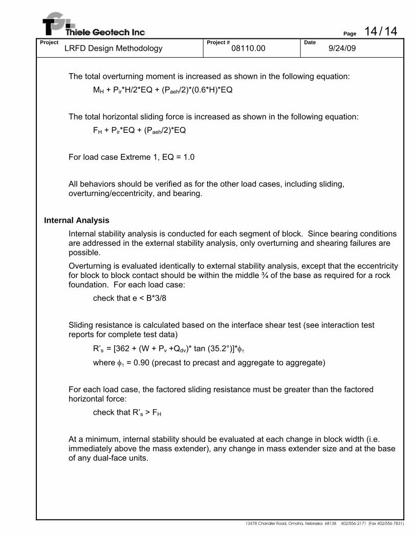
The total overturning moment is increased as shown in the following equation:
MH + Pir*H/2*EQ + (Paeh/2)*(0.6*H)*EQ The total horizontal sliding force is increased as shown in the following equation:
FH + Pir*EQ + (Paeh/2)*EQ For load case Extreme 1, EQ = 1.0 All behaviors should be verified as for the other load cases, including sliding, overturning/eccentricity, and bearing.
Internal Analysis Internal stability analysis is conducted for each segment of block. Since bearing conditions are addressed in the external stability analysis, only overturning and shearing failures are possible. Overturning is evaluated identically to external stability analysis, except that the eccentricity for block to block contact should be within the middle ¾ of the base as required for a rock foundation. For each load case:
check that e < B*3/8 Sliding resistance is calculated based on the interface shear test (see interaction test reports for complete test data)
R’s = [362 + (W + Pv +Qdv)* tan (35.2°)]*φτ where φτ = 0.90 (precast to precast and aggregate to aggregate)
For each load case, the factored sliding resistance must be greater than the factored horizontal force:
check that R’s > FH At a minimum, internal stability should be evaluated at each change in block width (i.e. immediately above the mass extender), any change in mass extender size and at the base of any dual-face units.
Page 1/12Project
LRFD Example Calculation Project #
08110.03 Date
7/10/10
13478 Chandler Road, Omaha, Nebraska 68138 402/556-2171 (Fax 402/556-7831)
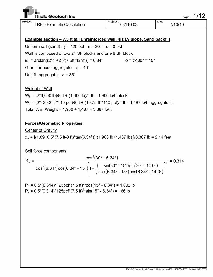
Example section – 7.5 ft tall unreinforced wall, 4H:1V slope, Sand backfill Uniform soil (sand) - γ = 125 pcf φ = 30° c = 0 psf Wall is composed of two 24 SF blocks and one 6 SF block ω’ = arctan((2*4”+2”)/(7.5ft*12”/ft)) = 6.34° δ = ½*30° = 15°
Granular base aggregate – φ = 40°
Unit fill aggregate – φ = 35° Weight of Wall Wb = (2*6,000 lb)/8 ft + (1,600 lb)/4 ft = 1,900 lb/ft block Wa = (2*43.32 ft3*110 pcf)/8 ft + (10.75 ft3*110 pcf)/4 ft = 1,487 lb/ft aggregate fill Total Wall Weight = 1,900 + 1,487 = 3,387 lb/ft
Forces/Geometric Properties Center of Gravity xw = [(1.89+0.5*(7.5 ft-3 ft)*tan(6.34°))*(1,900 lb+1,487 lb) ]/3,387 lb = 2.14 feet Soil force components
( )
( ) ( ) ( ) ( )( ) ( )
2
2
2
a
0.4134.6cos 1534.6 cos0.4130sin 1530sin11534.6cos 34.6cos
6.3430cosK
⎥⎦
⎤⎢⎣
⎡
°+°°−°°−°°+°
+°−°°
°+°= = 0.314
Ph = 0.5*(0.314)*125pcf*(7.5 ft)2*cos(15° - 6.34°) = 1,092 lb Pv = 0.5*(0.314)*125pcf*(7.5 ft)2*sin(15° - 6.34°) = 166 lb

Page 2/12Project
LRFD Example Calculation Project #
08110.03 Date
7/10/10
13478 Chandler Road, Omaha, Nebraska 68138 402/556-2171 (Fax 402/556-7831)
Table of Unfactored Forces & Moments
Force x Moment about toe
(lb) (ft) (lb*ft)
Vertical Forces
weight of wall 3,387 2.14 7,248 modified weight 3,090 2.14 6,613
earth pressure 166 3.94 654 DL surcharge 0 4.08 0
Horizontal Forces
earth pressure 1,092 2.50 2,730 DL surcharge 0 3.75 0
LL surcharge 0 3.75 0
Table of Load & Resistance Factors Strength Strength Strength Service I-a I-b IV I
Load Factors DL/ES 1.50 1.00 1.50 1.00
LL 1.75 1.75 0.00 1.00
EH 1.50 1.50 1.50 1.00 EQ 0.00 0.00 0.00 0.00
Resistance Factors
DC 0.90 1.25 1.50 1.00 EV 1.00 1.35 1.35 1.00
BC 0.50 0.50 0.50 0.50
Page 3/12Project
LRFD Example Calculation Project #
08110.03 Date
7/10/10
13478 Chandler Road, Omaha, Nebraska 68138 402/556-2171 (Fax 402/556-7831)
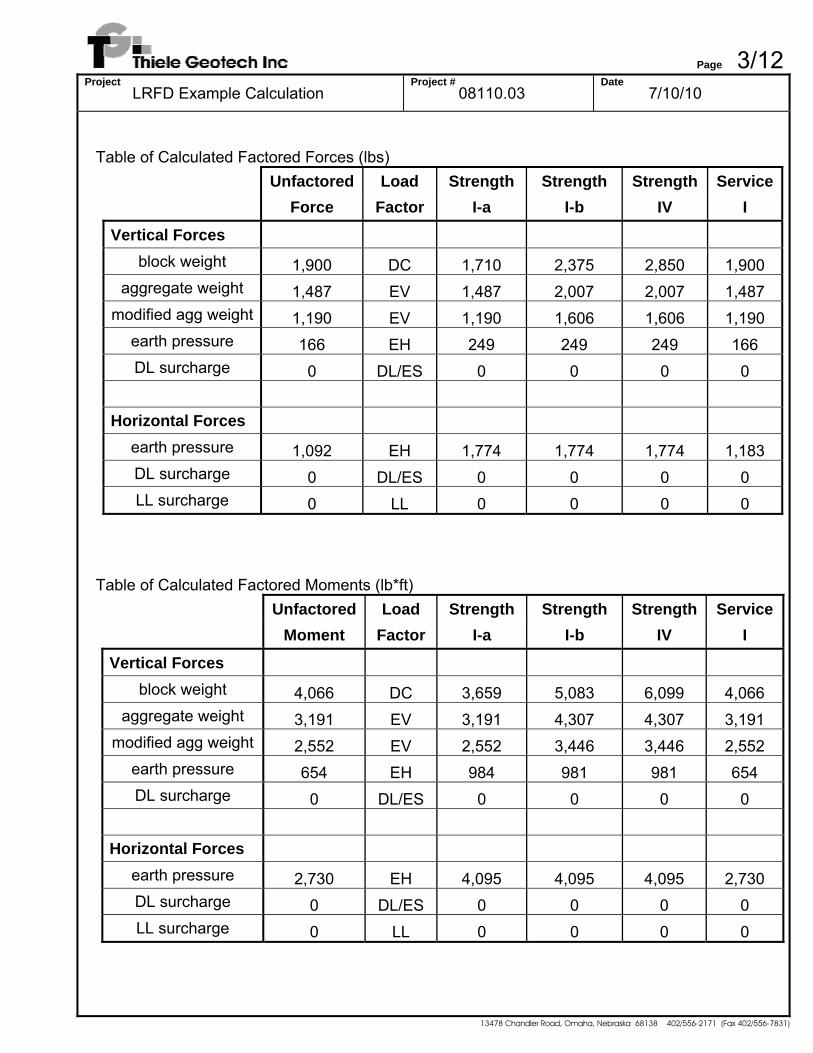
Table of Calculated Factored Forces (lbs)
Unfactored Load Strength Strength Strength Service Force Factor I-a I-b IV I
Vertical Forces block weight 1,900 DC 1,710 2,375 2,850 1,900
aggregate weight 1,487 EV 1,487 2,007 2,007 1,487 modified agg weight 1,190 EV 1,190 1,606 1,606 1,190
earth pressure 166 EH 249 249 249 166 DL surcharge 0 DL/ES 0 0 0 0
Horizontal Forces
earth pressure 1,092 EH 1,774 1,774 1,774 1,183 DL surcharge 0 DL/ES 0 0 0 0 LL surcharge 0 LL 0 0 0 0
Table of Calculated Factored Moments (lb*ft)
Unfactored Load Strength Strength Strength Service Moment Factor I-a I-b IV I
Vertical Forces
block weight 4,066 DC 3,659 5,083 6,099 4,066 aggregate weight 3,191 EV 3,191 4,307 4,307 3,191
modified agg weight 2,552 EV 2,552 3,446 3,446 2,552 earth pressure 654 EH 984 981 981 654 DL surcharge 0 DL/ES 0 0 0 0
Horizontal Forces
earth pressure 2,730 EH 4,095 4,095 4,095 2,730 DL surcharge 0 DL/ES 0 0 0 0 LL surcharge 0 LL 0 0 0 0
Page 4/12Project
LRFD Example Calculation Project #
08110.03 Date
7/10/10
13478 Chandler Road, Omaha, Nebraska 68138 402/556-2171 (Fax 402/556-7831)
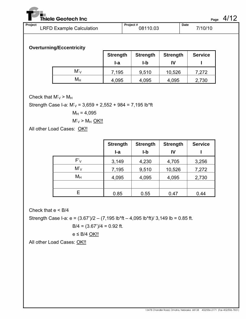
Overturning/Eccentricity
Strength Strength Strength Service I-a I-b IV I
M’V 7,195 9,510 10,526 7,272 MH 4,095 4,095 4,095 2,730
Check that M’V > MH Strength Case I-a: M’V = 3,659 + 2,552 + 984 = 7,195 lb*ft
MH = 4,095 M’V > MH OK!!
All other Load Cases: OK!!
Strength Strength Strength Service I-a I-b IV I
F’V 3,149 4,230 4,705 3,256 M’V 7,195 9,510 10,526 7,272 MH 4,095 4,095 4,095 2,730
E 0.85 0.55 0.47 0.44
Check that e < B/4 Strength Case I-a: e = (3.67’)/2 – (7,195 lb*ft – 4,095 lb*ft)/ 3,149 lb = 0.85 ft.
B/4 = (3.67’)/4 = 0.92 ft. e ≤ B/4 OK!! All other Load Cases: OK!!
Page 5/12Project
LRFD Example Calculation Project #
08110.03 Date
7/10/10
13478 Chandler Road, Omaha, Nebraska 68138 402/556-2171 (Fax 402/556-7831)
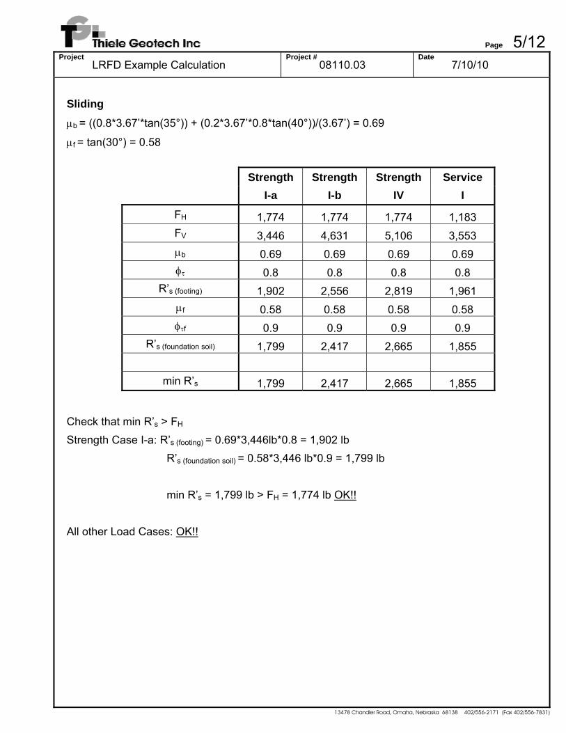
Sliding μb = ((0.8*3.67’*tan(35°)) + (0.2*3.67’*0.8*tan(40°))/(3.67’) = 0.69
μf = tan(30°) = 0.58
Strength Strength Strength Service I-a I-b IV I
FH 1,774 1,774 1,774 1,183 FV 3,446 4,631 5,106 3,553 μb 0.69 0.69 0.69 0.69 φτ 0.8 0.8 0.8 0.8
R’s (footing) 1,902 2,556 2,819 1,961 μf 0.58 0.58 0.58 0.58 φτf 0.9 0.9 0.9 0.9
R’s (foundation soil) 1,799 2,417 2,665 1,855
min R’s 1,799 2,417 2,665 1,855
Check that min R’s > FH Strength Case I-a: R’s (footing) = 0.69*3,446lb*0.8 = 1,902 lb
R’s (foundation soil) = 0.58*3,446 lb*0.9 = 1,799 lb min R’s = 1,799 lb > FH = 1,774 lb OK!!
All other Load Cases: OK!!
Page 6/12Project
LRFD Example Calculation Project #
08110.03 Date
7/10/10
13478 Chandler Road, Omaha, Nebraska 68138 402/556-2171 (Fax 402/556-7831)
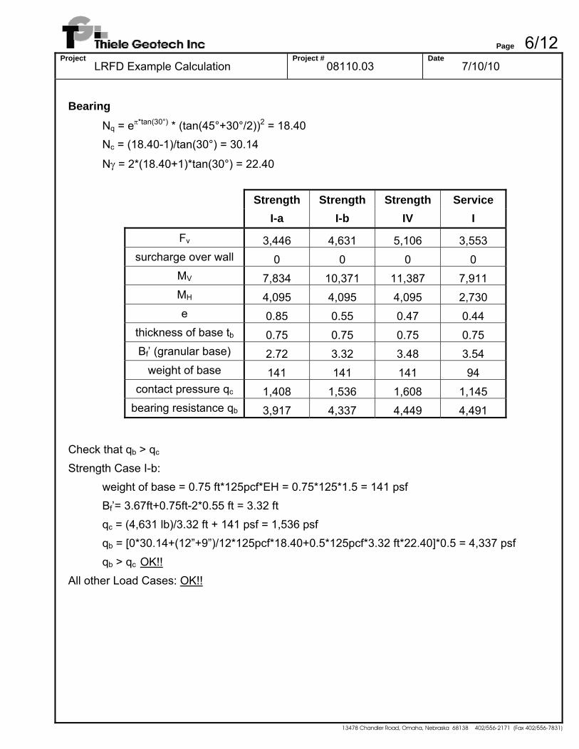
Bearing Nq = eπ*tan(30°) * (tan(45°+30°/2))2 = 18.40
Nc = (18.40-1)/tan(30°) = 30.14
Nγ = 2*(18.40+1)*tan(30°) = 22.40
Strength Strength Strength Service I-a I-b IV I
Fv 3,446 4,631 5,106 3,553 surcharge over wall 0 0 0 0
MV 7,834 10,371 11,387 7,911 MH 4,095 4,095 4,095 2,730 e 0.85 0.55 0.47 0.44
thickness of base tb 0.75 0.75 0.75 0.75 Bf’ (granular base) 2.72 3.32 3.48 3.54
weight of base 141 141 141 94 contact pressure qc 1,408 1,536 1,608 1,145
bearing resistance qb 3,917 4,337 4,449 4,491
Check that qb > qc Strength Case I-b:
weight of base = 0.75 ft*125pcf*EH = 0.75*125*1.5 = 141 psf Bf’= 3.67ft+0.75ft-2*0.55 ft = 3.32 ft qc = (4,631 lb)/3.32 ft + 141 psf = 1,536 psf qb = [0*30.14+(12”+9”)/12*125pcf*18.40+0.5*125pcf*3.32 ft*22.40]*0.5 = 4,337 psf
qb > qc OK!! All other Load Cases: OK!!

Page 7/12Project
LRFD Example Calculation Project #
08110.03 Date
7/10/10
13478 Chandler Road, Omaha, Nebraska 68138 402/556-2171 (Fax 402/556-7831)
Internal Analysis For 4.5 ft. tall segment above the bottom course. Table of Unfactored Forces & Moments
Force x Moment about toe
(lb) (ft) (lb*ft)
Vertical Forces weight of wall 2,041 1.98 4,041
modified weight 1,863 1.98 3,689 earth pressure 60 3.83 230 DL surcharge 0 3.92 0
Horizontal Forces
earth pressure 393 1.50 590 DL surcharge 0 2.25 0 LL surcharge 0 2.25 0
Table of Calculated Factored Forces (lbs)
Unfactored Load Strength Strength Strength Service Force Factor I-a I-b IV I
Vertical Forces block weight 1,150 DC 1,035 1,438 1,725 1,150
aggregate weight 891 EV 891 1,203 1,203 891 modified agg weight 713 EV 713 963 963 713
earth pressure 60 EH 90 90 90 60 DL surcharge 0 DL/ES 0 0 0 0
Horizontal Forces
earth pressure 393 EH 590 590 590 393 DL surcharge 0 DL/ES 0 0 0 0 LL surcharge 0 LL 0 0 0 0
Page 8/12Project
LRFD Example Calculation Project #
08110.03 Date
7/10/10
13478 Chandler Road, Omaha, Nebraska 68138 402/556-2171 (Fax 402/556-7831)
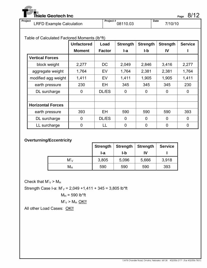
Table of Calculated Factored Moments (lb*ft)
Unfactored Load Strength Strength Strength Service Moment Factor I-a I-b IV I
Vertical Forces
block weight 2,277 DC 2,049 2,846 3,416 2,277 aggregate weight 1,764 EV 1,764 2,381 2,381 1,764
modified agg weight 1,411 EV 1,411 1,905 1,905 1,411 earth pressure 230 EH 345 345 345 230
DL surcharge 0 DL/ES 0 0 0 0
Horizontal Forces earth pressure 393 EH 590 590 590 393
DL surcharge 0 DL/ES 0 0 0 0 LL surcharge 0 LL 0 0 0 0
Overturning/Eccentricity
Strength Strength Strength Service I-a I-b IV I
M’V 3,805 5,096 5,666 3,918 MH 590 590 590 393
Check that M’V > MH Strength Case I-a: M’V = 2,049 +1,411 + 345 = 3,805 lb*ft
MH = 590 lb*ft M’V > MH OK!!
All other Load Cases: OK!!
Page 9/12Project
LRFD Example Calculation Project #
08110.03 Date
7/10/10
13478 Chandler Road, Omaha, Nebraska 68138 402/556-2171 (Fax 402/556-7831)
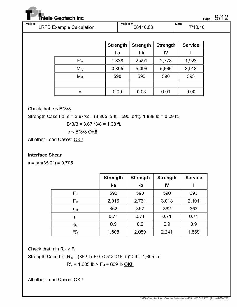
Strength Strength Strength Service I-a I-b IV I
F’V 1,838 2,491 2,778 1,923
M’V 3,805 5,096 5,666 3,918 MH 590 590 590 393
e 0.09 0.03 0.01 0.00
Check that e < B*3/8 Strength Case I-a: e = 3.67’/2 – (3,805 lb*ft – 590 lb*ft)/ 1,838 lb = 0.09 ft. B*3/8 = 3.67’*3/8 = 1.38 ft. e < B*3/8 OK!! All other Load Cases: OK!! Interface Shear μ = tan(35.2°) = 0.705
Strength Strength Strength Service I-a I-b IV I
FH 590 590 590 393 FV 2,016 2,731 3,018 2,101
ιult 362 362 362 362
μ 0.71 0.71 0.71 0.71
φτ 0.9 0.9 0.9 0.9 R’s 1,605 2,059 2,241 1,659
Check that min R’s > FH Strength Case I-a: R’s = (362 lb + 0.705*2,016 lb)*0.9 = 1,605 lb R’s = 1,605 lb > FH = 639 lb OK!! All other Load Cases: OK!!
Page 10/12Project
LRFD Example Calculation Project #
08110.03 Date
7/10/10
13478 Chandler Road, Omaha, Nebraska 68138 402/556-2171 (Fax 402/556-7831)
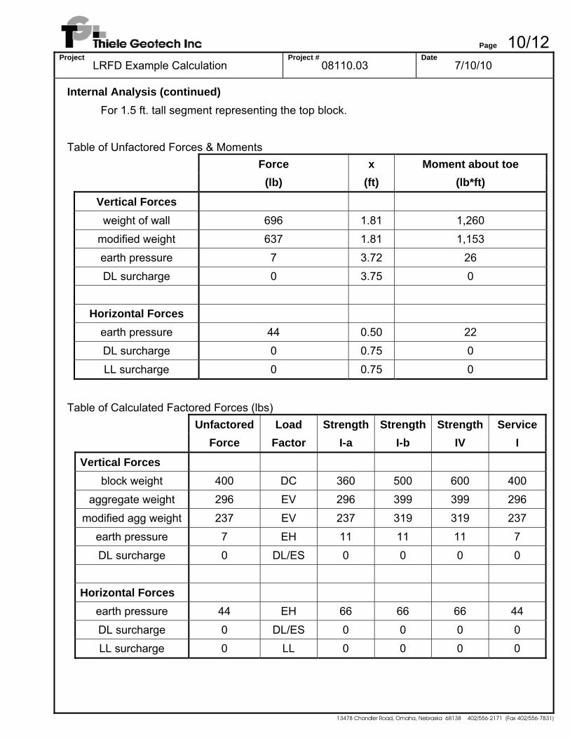
Internal Analysis (continued) For 1.5 ft. tall segment representing the top block. Table of Unfactored Forces & Moments
Force x Moment about toe
(lb) (ft) (lb*ft)
Vertical Forces
weight of wall 696 1.81 1,260 modified weight 637 1.81 1,153
earth pressure 7 3.72 26 DL surcharge 0 3.75 0
Horizontal Forces
earth pressure 44 0.50 22 DL surcharge 0 0.75 0
LL surcharge 0 0.75 0
Table of Calculated Factored Forces (lbs)
Unfactored Load Strength Strength Strength Service Force Factor I-a I-b IV I
Vertical Forces
block weight 400 DC 360 500 600 400 aggregate weight 296 EV 296 399 399 296
modified agg weight 237 EV 237 319 319 237 earth pressure 7 EH 11 11 11 7
DL surcharge 0 DL/ES 0 0 0 0
Horizontal Forces earth pressure 44 EH 66 66 66 44
DL surcharge 0 DL/ES 0 0 0 0 LL surcharge 0 LL 0 0 0 0
Page 11/12Project
LRFD Example Calculation Project #
08110.03 Date
7/10/10
13478 Chandler Road, Omaha, Nebraska 68138 402/556-2171 (Fax 402/556-7831)
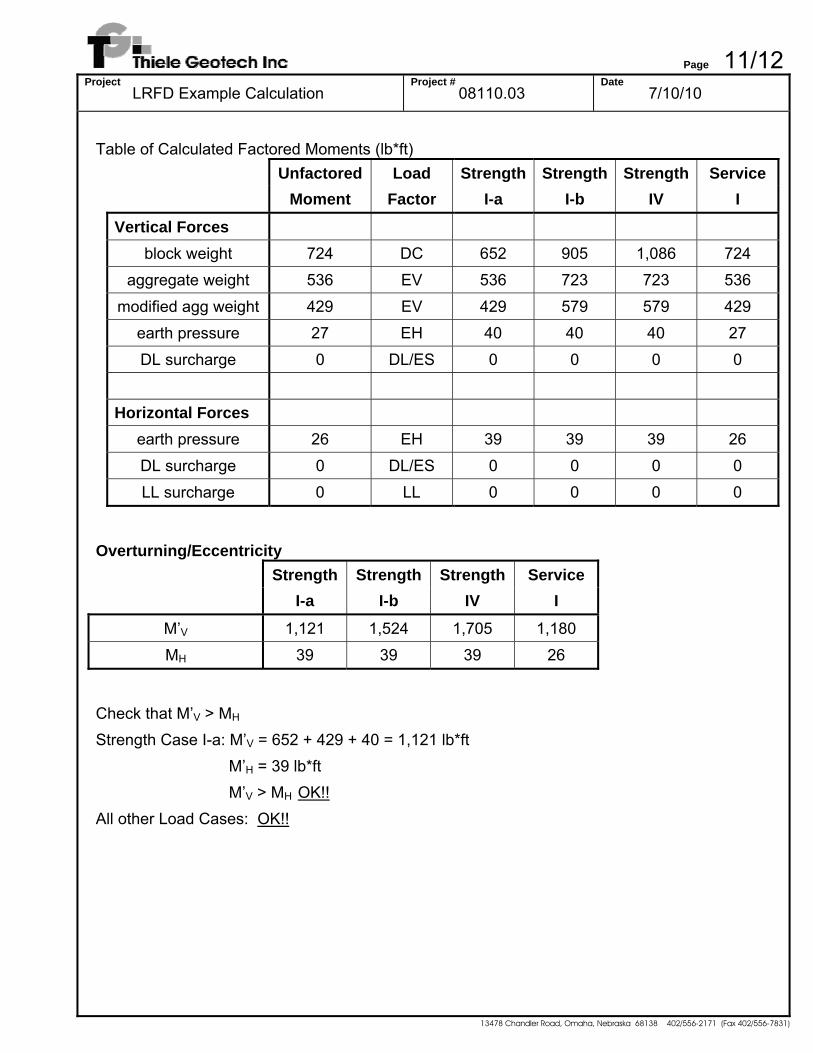
Table of Calculated Factored Moments (lb*ft)
Unfactored Load Strength Strength Strength Service Moment Factor I-a I-b IV I
Vertical Forces
block weight 724 DC 652 905 1,086 724 aggregate weight 536 EV 536 723 723 536
modified agg weight 429 EV 429 579 579 429 earth pressure 27 EH 40 40 40 27
DL surcharge 0 DL/ES 0 0 0 0
Horizontal Forces earth pressure 26 EH 39 39 39 26
DL surcharge 0 DL/ES 0 0 0 0 LL surcharge 0 LL 0 0 0 0
Overturning/Eccentricity
Strength Strength Strength Service I-a I-b IV I
M’V 1,121 1,524 1,705 1,180 MH 39 39 39 26
Check that M’V > MH Strength Case I-a: M’V = 652 + 429 + 40 = 1,121 lb*ft M’H = 39 lb*ft M’V > MH OK!! All other Load Cases: OK!!
Page 12/12Project
LRFD Example Calculation Project #
08110.03 Date
7/10/10
13478 Chandler Road, Omaha, Nebraska 68138 402/556-2171 (Fax 402/556-7831)
Strength Strength Strength Service I-a I-b IV I
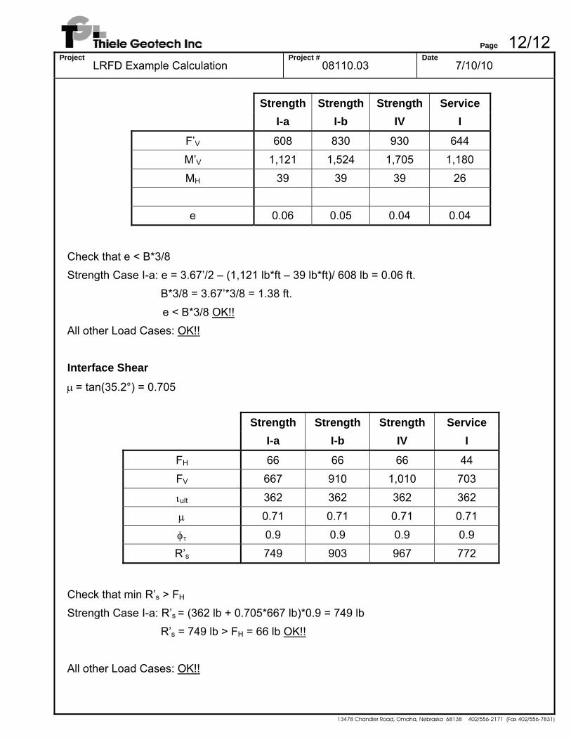
F’V 608 830 930 644
M’V 1,121 1,524 1,705 1,180 MH 39 39 39 26
e 0.06 0.05 0.04 0.04
Check that e < B*3/8 Strength Case I-a: e = 3.67’/2 – (1,121 lb*ft – 39 lb*ft)/ 608 lb = 0.06 ft. B*3/8 = 3.67’*3/8 = 1.38 ft. e < B*3/8 OK!! All other Load Cases: OK!! Interface Shear μ = tan(35.2°) = 0.705
Strength Strength Strength Service I-a I-b IV I
FH 66 66 66 44 FV 667 910 1,010 703
ιult 362 362 362 362
μ 0.71 0.71 0.71 0.71
φτ 0.9 0.9 0.9 0.9 R’s 749 903 967 772
Check that min R’s > FH Strength Case I-a: R’s = (362 lb + 0.705*667 lb)*0.9 = 749 lb R’s = 749 lb > FH = 66 lb OK!! All other Load Cases: OK!!
Page 1/12Project
LRFD Example Calculation Project #
08110.04 Date
9/24/09
13478 Chandler Road, Omaha, Nebraska 68138 402/556-2171 (Fax 402/556-7831)
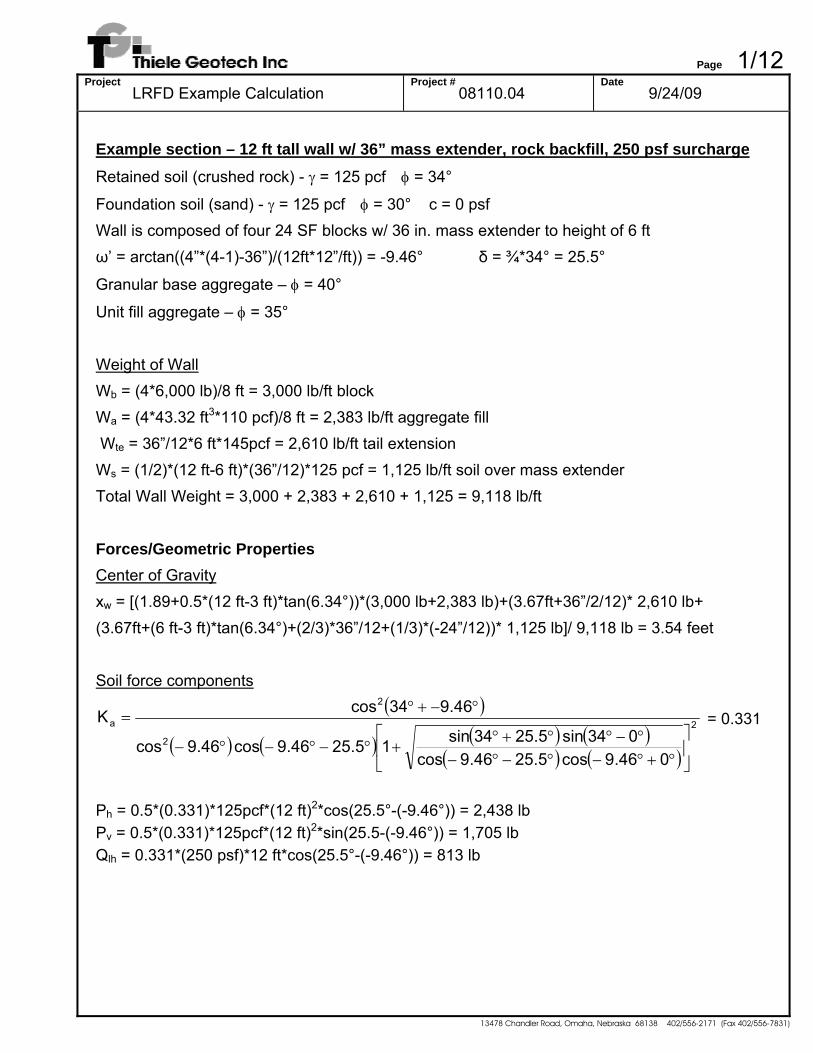
Example section – 12 ft tall wall w/ 36” mass extender, rock backfill, 250 psf surcharge Retained soil (crushed rock) - γ = 125 pcf φ = 34°
Foundation soil (sand) - γ = 125 pcf φ = 30° c = 0 psf Wall is composed of four 24 SF blocks w/ 36 in. mass extender to height of 6 ft ω’ = arctan((4”*(4-1)-36”)/(12ft*12”/ft)) = -9.46° δ = ¾*34° = 25.5°
Granular base aggregate – φ = 40°
Unit fill aggregate – φ = 35° Weight of Wall Wb = (4*6,000 lb)/8 ft = 3,000 lb/ft block Wa = (4*43.32 ft3*110 pcf)/8 ft = 2,383 lb/ft aggregate fill Wte = 36”/12*6 ft*145pcf = 2,610 lb/ft tail extension Ws = (1/2)*(12 ft-6 ft)*(36”/12)*125 pcf = 1,125 lb/ft soil over mass extender Total Wall Weight = 3,000 + 2,383 + 2,610 + 1,125 = 9,118 lb/ft
Forces/Geometric Properties Center of Gravity xw = [(1.89+0.5*(12 ft-3 ft)*tan(6.34°))*(3,000 lb+2,383 lb)+(3.67ft+36”/2/12)* 2,610 lb+ (3.67ft+(6 ft-3 ft)*tan(6.34°)+(2/3)*36”/12+(1/3)*(-24”/12))* 1,125 lb]/ 9,118 lb = 3.54 feet Soil force components
( )
( ) ( ) ( ) ( )( ) ( )
2
2
2
a
046.9cos 25.546.9cos034sin 25.534sin125.546.9cos 46.9cos
46.934cosK
⎥⎦
⎤⎢⎣
⎡
°+°−°−°−°−°°+°
+°−°−°−
°−+°= = 0.331
Ph = 0.5*(0.331)*125pcf*(12 ft)2*cos(25.5°-(-9.46°)) = 2,438 lb Pv = 0.5*(0.331)*125pcf*(12 ft)2*sin(25.5-(-9.46°)) = 1,705 lb Qlh = 0.331*(250 psf)*12 ft*cos(25.5°-(-9.46°)) = 813 lb
Page 2/12Project
LRFD Example Calculation Project #
08110.04 Date
9/24/09
13478 Chandler Road, Omaha, Nebraska 68138 402/556-2171 (Fax 402/556-7831)
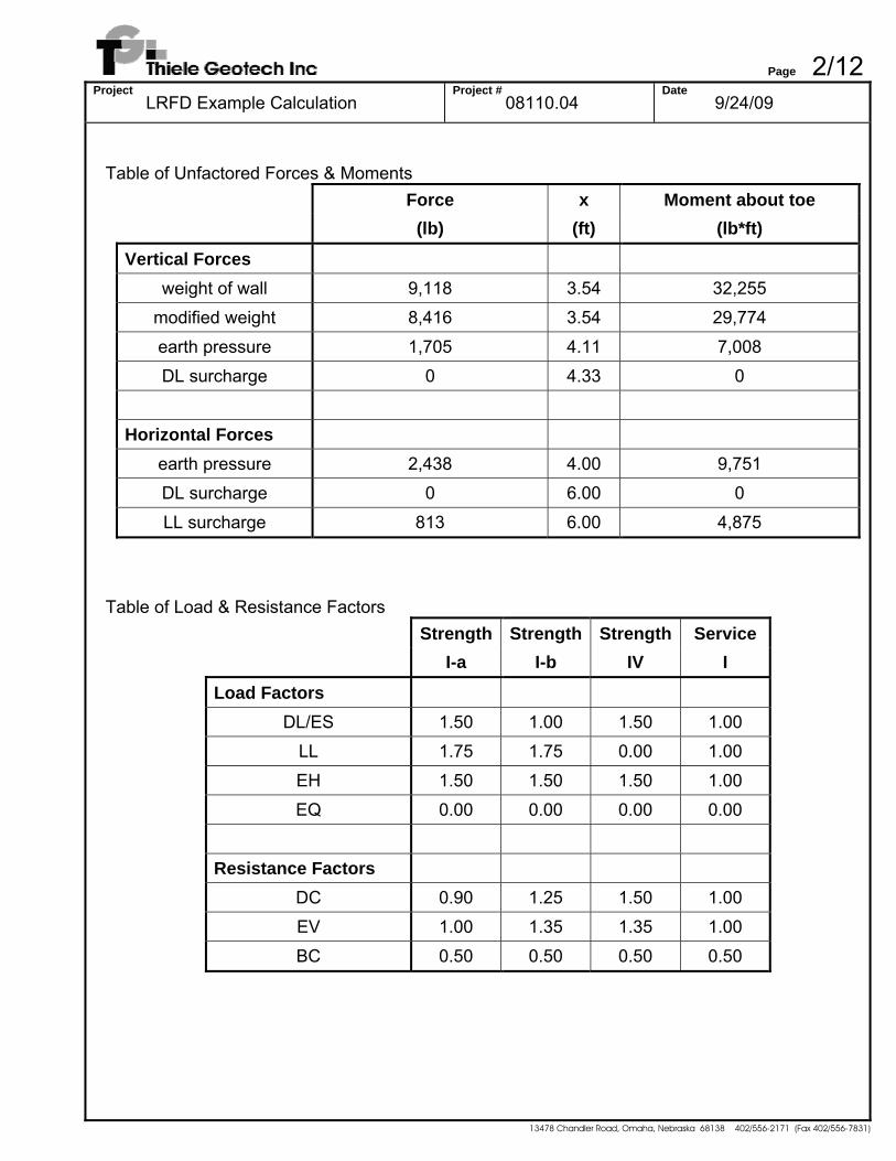
Table of Unfactored Forces & Moments
Force x Moment about toe
(lb) (ft) (lb*ft)
Vertical Forces
weight of wall 9,118 3.54 32,255 modified weight 8,416 3.54 29,774
earth pressure 1,705 4.11 7,008 DL surcharge 0 4.33 0
Horizontal Forces
earth pressure 2,438 4.00 9,751 DL surcharge 0 6.00 0
LL surcharge 813 6.00 4,875
Table of Load & Resistance Factors Strength Strength Strength Service I-a I-b IV I
Load Factors DL/ES 1.50 1.00 1.50 1.00
LL 1.75 1.75 0.00 1.00
EH 1.50 1.50 1.50 1.00 EQ 0.00 0.00 0.00 0.00
Resistance Factors
DC 0.90 1.25 1.50 1.00 EV 1.00 1.35 1.35 1.00
BC 0.50 0.50 0.50 0.50
Page 3/12Project
LRFD Example Calculation Project #
08110.04 Date
9/24/09
13478 Chandler Road, Omaha, Nebraska 68138 402/556-2171 (Fax 402/556-7831)
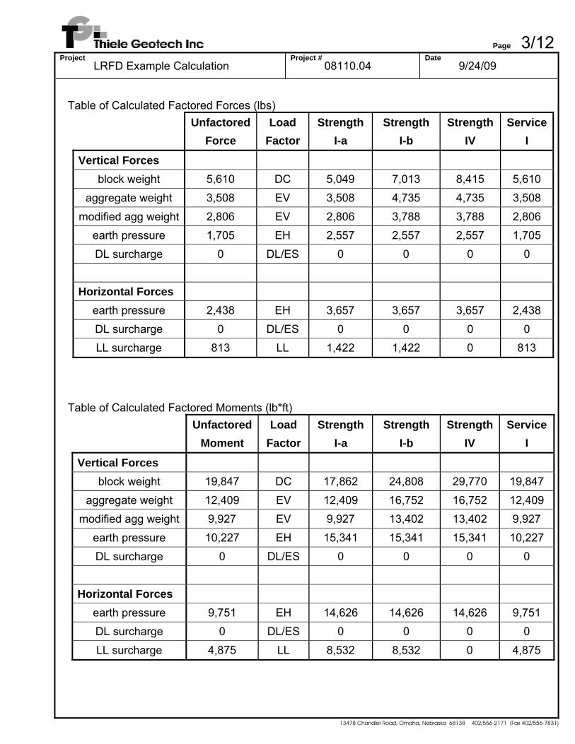
Table of Calculated Factored Forces (lbs)
Unfactored Load Strength Strength Strength Service Force Factor I-a I-b IV I
Vertical Forces
block weight 5,610 DC 5,049 7,013 8,415 5,610 aggregate weight 3,508 EV 3,508 4,735 4,735 3,508
modified agg weight 2,806 EV 2,806 3,788 3,788 2,806 earth pressure 1,705 EH 2,557 2,557 2,557 1,705
DL surcharge 0 DL/ES 0 0 0 0
Horizontal Forces earth pressure 2,438 EH 3,657 3,657 3,657 2,438
DL surcharge 0 DL/ES 0 0 0 0 LL surcharge 813 LL 1,422 1,422 0 813
Table of Calculated Factored Moments (lb*ft)
Unfactored Load Strength Strength Strength Service Moment Factor I-a I-b IV I
Vertical Forces block weight 19,847 DC 17,862 24,808 29,770 19,847
aggregate weight 12,409 EV 12,409 16,752 16,752 12,409 modified agg weight 9,927 EV 9,927 13,402 13,402 9,927
earth pressure 10,227 EH 15,341 15,341 15,341 10,227 DL surcharge 0 DL/ES 0 0 0 0
Horizontal Forces
earth pressure 9,751 EH 14,626 14,626 14,626 9,751 DL surcharge 0 DL/ES 0 0 0 0
LL surcharge 4,875 LL 8,532 8,532 0 4,875
Page 4/12Project
LRFD Example Calculation Project #
08110.04 Date
9/24/09
13478 Chandler Road, Omaha, Nebraska 68138 402/556-2171 (Fax 402/556-7831)
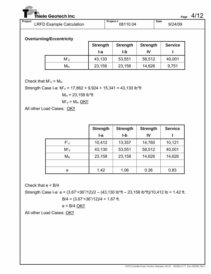
Overturning/Eccentricity
Strength Strength Strength Service I-a I-b IV I
M’V 43,130 53,551 58,512 40,001
MH 23,158 23,158 14,626 9,751
Check that M’V > MH Strength Case I-a: M’V = 17,862 + 9,924 + 15,341 = 43,130 lb*ft
MH = 23,158 lb*ft M’V > MH OK!!
All other Load Cases: OK!!
Strength Strength Strength Service I-a I-b IV I
F’V 10,412 13,357 14,760 10,121
M’V 43,130 53,551 58,512 40,001 MH 23,158 23,158 14,626 14,626
e 1.42 1.06 0.36 0.83
Check that e < B/4 Strength Case I-a: e = (3.67’+36”/12)/2 – (43,130 lb*ft – 23,158 lb*ft)/10,412 lb = 1.42 ft.
B/4 = (3.67’+36”/12)/4 = 1.67 ft. e < B/4 OK!!
All other Load Cases: OK!!
Page 5/12Project
LRFD Example Calculation Project #
08110.04 Date
9/24/09
13478 Chandler Road, Omaha, Nebraska 68138 402/556-2171 (Fax 402/556-7831)
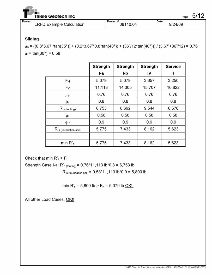
Sliding μb = ((0.8*3.67’*tan(35°)) + (0.2*3.67’*0.8*tan(40°)) + (36”/12*tan(40°))) / (3.67’+36”/12) = 0.76
μf = tan(30°) = 0.58
Strength Strength Strength Service I-a I-b IV I
FH 5,079 5,079 3,657 3,250
FV 11,113 14,305 15,707 10,822
μb 0.76 0.76 0.76 0.76
φτ 0.8 0.8 0.8 0.8 R’s (footing) 6,753 8,692 9,544 6,576
μf 0.58 0.58 0.58 0.58
φτf 0.9 0.9 0.9 0.9
R’s (foundation soil) 5,775 7,433 8,162 5,623
min R’s 5,775 7,433 8,162 5,623
Check that min R’s > FH Strength Case I-a: R’s (footing) = 0.76*11,113 lb*0.8 = 6,753 lb
R’s (foundation soil) = 0.58*11,113 lb*0.9 = 5,800 lb min R’s = 5,800 lb > FH = 5,079 lb OK!!
All other Load Cases: OK!!
Page 6/12Project
LRFD Example Calculation Project #
08110.04 Date
9/24/09
13478 Chandler Road, Omaha, Nebraska 68138 402/556-2171 (Fax 402/556-7831)
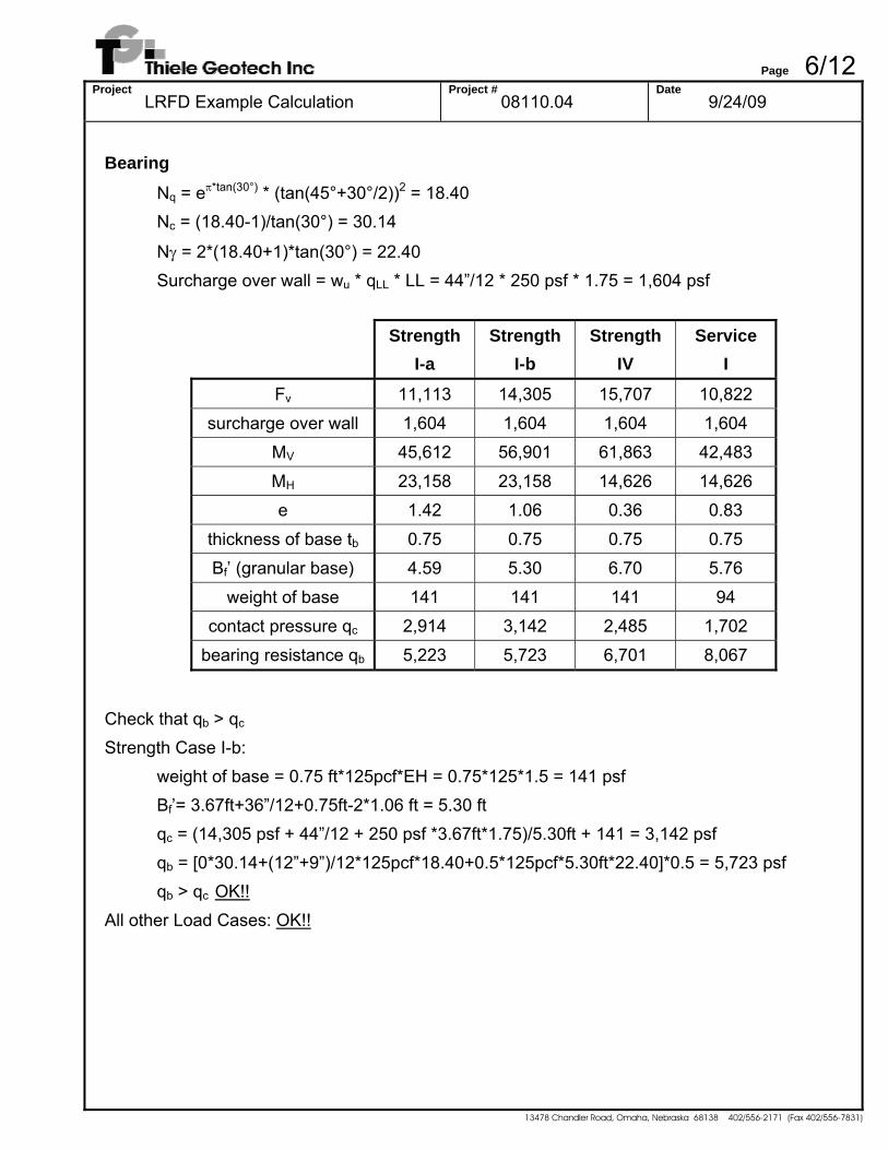
Bearing Nq = eπ*tan(30°) * (tan(45°+30°/2))2 = 18.40
Nc = (18.40-1)/tan(30°) = 30.14
Nγ = 2*(18.40+1)*tan(30°) = 22.40 Surcharge over wall = wu * qLL * LL = 44”/12 * 250 psf * 1.75 = 1,604 psf
Strength Strength Strength Service I-a I-b IV I
Fv 11,113 14,305 15,707 10,822
surcharge over wall 1,604 1,604 1,604 1,604 MV 45,612 56,901 61,863 42,483
MH 23,158 23,158 14,626 14,626 e 1.42 1.06 0.36 0.83
thickness of base tb 0.75 0.75 0.75 0.75 Bf’ (granular base) 4.59 5.30 6.70 5.76
weight of base 141 141 141 94 contact pressure qc 2,914 3,142 2,485 1,702
bearing resistance qb 5,223 5,723 6,701 8,067
Check that qb > qc Strength Case I-b:
weight of base = 0.75 ft*125pcf*EH = 0.75*125*1.5 = 141 psf Bf’= 3.67ft+36”/12+0.75ft-2*1.06 ft = 5.30 ft qc = (14,305 psf + 44”/12 + 250 psf *3.67ft*1.75)/5.30ft + 141 = 3,142 psf qb = [0*30.14+(12”+9”)/12*125pcf*18.40+0.5*125pcf*5.30ft*22.40]*0.5 = 5,723 psf
qb > qc OK!! All other Load Cases: OK!!
Page 7/12Project
LRFD Example Calculation Project #
08110.04 Date
9/24/09
13478 Chandler Road, Omaha, Nebraska 68138 402/556-2171 (Fax 402/556-7831)
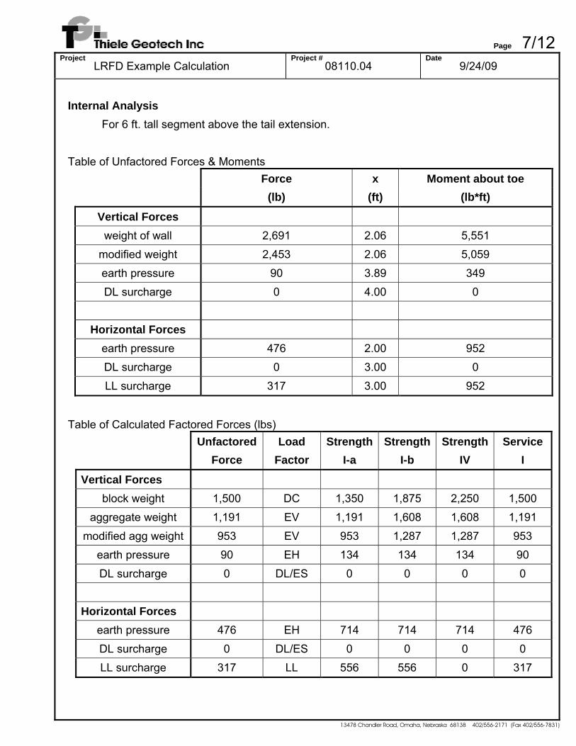
Internal Analysis For 6 ft. tall segment above the tail extension. Table of Unfactored Forces & Moments
Force x Moment about toe
(lb) (ft) (lb*ft)
Vertical Forces
weight of wall 2,691 2.06 5,551 modified weight 2,453 2.06 5,059
earth pressure 90 3.89 349 DL surcharge 0 4.00 0
Horizontal Forces
earth pressure 476 2.00 952 DL surcharge 0 3.00 0
LL surcharge 317 3.00 952
Table of Calculated Factored Forces (lbs)
Unfactored Load Strength Strength Strength Service Force Factor I-a I-b IV I
Vertical Forces
block weight 1,500 DC 1,350 1,875 2,250 1,500 aggregate weight 1,191 EV 1,191 1,608 1,608 1,191
modified agg weight 953 EV 953 1,287 1,287 953 earth pressure 90 EH 134 134 134 90
DL surcharge 0 DL/ES 0 0 0 0
Horizontal Forces earth pressure 476 EH 714 714 714 476
DL surcharge 0 DL/ES 0 0 0 0 LL surcharge 317 LL 556 556 0 317

Page 8/12Project
LRFD Example Calculation Project #
08110.04 Date
9/24/09
13478 Chandler Road, Omaha, Nebraska 68138 402/556-2171 (Fax 402/556-7831)
Table of Calculated Factored Moments (lb*ft)
Unfactored Load Strength Strength Strength Service Moment Factor I-a I-b IV I
Vertical Forces
block weight 3,094 DC 2,784 3,867 4,640 3,094 aggregate weight 2,457 EV 2,457 3,317 3,317 2,457
modified agg weight 1,966 EV 1,966 2,654 2,654 1,966 earth pressure 349 EH 523 523 523 349
DL surcharge 0 DL/ES 0 0 0 0
Horizontal Forces earth pressure 952 EH 1,429 1,429 1,429 952
DL surcharge 0 DL/ES 0 0 0 0 LL surcharge 952 LL 1,667 1,667 0 952
Overturning/Eccentricity
Strength Strength Strength Service I-a I-b IV I
M’V 5,273 7,043 7,817 5,408 MH 3,095 3,095 1,429 1,905
Check that M’V > MH Strength Case I-a: M’V = 2,784 + 1,966 + 523 = 5,273 lb*ft
M’H = 3,095 lb*ft M’V > MH OK!!
All other Load Cases: OK!!

Page 9/12Project
LRFD Example Calculation Project #
08110.04 Date
9/24/09
13478 Chandler Road, Omaha, Nebraska 68138 402/556-2171 (Fax 402/556-7831)
Strength Strength Strength Service I-a I-b IV I
F’V 2,437 3,296 3,671 2,543
M’V 5,273 7,043 7,817 5,408 MH 3,095 3,095 1,429 1,905
e 0.94 0.64 0.09 0.46
Check that e < B*3/8 Strength Case I-a: e = 3.67’/2 – (5,273 lb*ft – 3,095 lb*ft)/2,437 lb = 0.94 ft.
B*3/8 = 3.67’*3/8 = 1.38 ft. e < B*3/8 OK!!
All other Load Cases: OK!! Interface Shear μ = tan(35.2°) = 0.705
Strength Strength Strength Service I-a I-b IV I
FH 1,270 1,270 714 794 FV 2,676 3,618 3,993 2,781
ιult 362 362 362 362
μ 0.71 0.71 0.71 0.71
φτ 0.9 0.9 0.9 0.9 R’s 2,025 2,623 2,861 2,091
Check that min R’s > FH Strength Case I-a: R’s = (362 lb + 0.705*2,676 lb)*0.9 = 2,025 lb
R’s = 2,025 lb > FH = 1,270 lb OK!! All other Load Cases: OK!!
Page 10/12Project
LRFD Example Calculation Project #
08110.04 Date
9/24/09
13478 Chandler Road, Omaha, Nebraska 68138 402/556-2171 (Fax 402/556-7831)
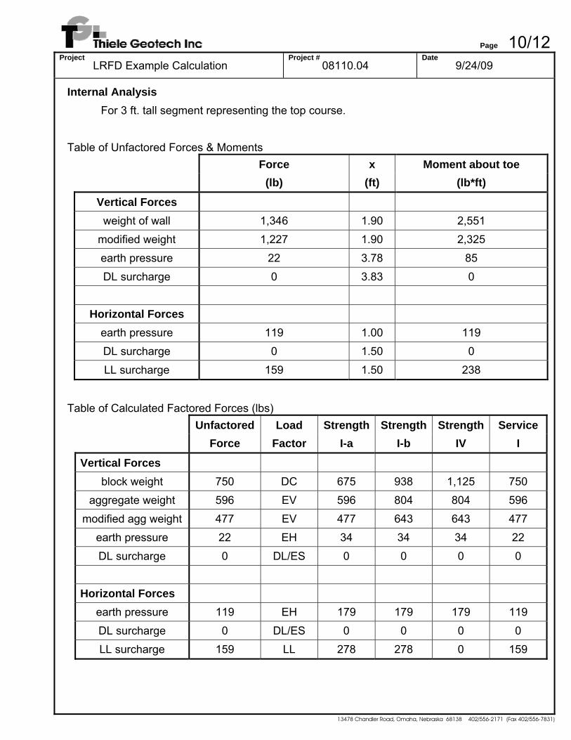
Internal Analysis For 3 ft. tall segment representing the top course. Table of Unfactored Forces & Moments
Force x Moment about toe
(lb) (ft) (lb*ft)
Vertical Forces
weight of wall 1,346 1.90 2,551 modified weight 1,227 1.90 2,325
earth pressure 22 3.78 85 DL surcharge 0 3.83 0
Horizontal Forces
earth pressure 119 1.00 119 DL surcharge 0 1.50 0
LL surcharge 159 1.50 238
Table of Calculated Factored Forces (lbs)
Unfactored Load Strength Strength Strength Service Force Factor I-a I-b IV I
Vertical Forces
block weight 750 DC 675 938 1,125 750 aggregate weight 596 EV 596 804 804 596
modified agg weight 477 EV 477 643 643 477 earth pressure 22 EH 34 34 34 22
DL surcharge 0 DL/ES 0 0 0 0
Horizontal Forces earth pressure 119 EH 179 179 179 119
DL surcharge 0 DL/ES 0 0 0 0 LL surcharge 159 LL 278 278 0 159
Page 11/12Project
LRFD Example Calculation Project #
08110.04 Date
9/24/09
13478 Chandler Road, Omaha, Nebraska 68138 402/556-2171 (Fax 402/556-7831)
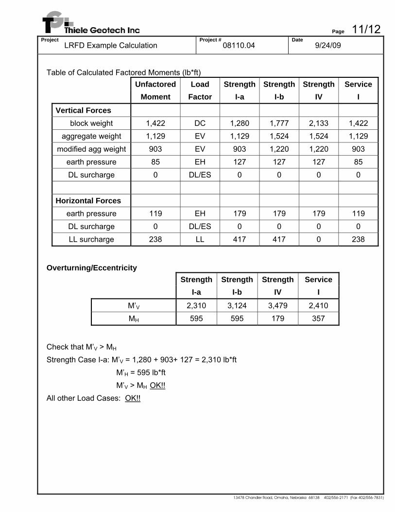
Table of Calculated Factored Moments (lb*ft)
Unfactored Load Strength Strength Strength Service Moment Factor I-a I-b IV I
Vertical Forces
block weight 1,422 DC 1,280 1,777 2,133 1,422 aggregate weight 1,129 EV 1,129 1,524 1,524 1,129
modified agg weight 903 EV 903 1,220 1,220 903 earth pressure 85 EH 127 127 127 85
DL surcharge 0 DL/ES 0 0 0 0
Horizontal Forces earth pressure 119 EH 179 179 179 119
DL surcharge 0 DL/ES 0 0 0 0 LL surcharge 238 LL 417 417 0 238
Overturning/Eccentricity
Strength Strength Strength Service I-a I-b IV I
M’V 2,310 3,124 3,479 2,410 MH 595 595 179 357
Check that M’V > MH Strength Case I-a: M’V = 1,280 + 903+ 127 = 2,310 lb*ft
M’H = 595 lb*ft M’V > MH OK!!
All other Load Cases: OK!!
Page 12/12Project
LRFD Example Calculation Project #
08110.04 Date
9/24/09
13478 Chandler Road, Omaha, Nebraska 68138 402/556-2171 (Fax 402/556-7831)
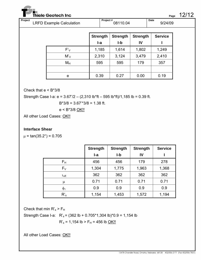
Strength Strength Strength Service I-a I-b IV I
F’V 1,185 1,614 1,802 1,249
M’V 2,310 3,124 3,479 2,410 MH 595 595 179 357
e 0.39 0.27 0.00 0.19
Check that e < B*3/8 Strength Case I-a: e = 3.67’/2 – (2,310 lb*ft – 595 lb*ft)/1,185 lb = 0.39 ft.
B*3/8 = 3.67’*3/8 = 1.38 ft. e < B*3/8 OK!!
All other Load Cases: OK!! Interface Shear μ = tan(35.2°) = 0.705
Strength Strength Strength Service I-a I-b IV I
FH 456 456 179 278 FV 1,304 1,775 1,963 1,368
ιult 362 362 362 362
μ 0.71 0.71 0.71 0.71
φτ 0.9 0.9 0.9 0.9 R’s 1,154 1,453 1,572 1,194
Check that min R’s > FH Strength Case I-a: R’s = (362 lb + 0.705*1,304 lb)*0.9 = 1,154 lb
R’s = 1,154 lb > FH = 456 lb OK!! All other Load Cases: OK!!
Top Related