


γλώσσες
Σελίδες
Νομικός

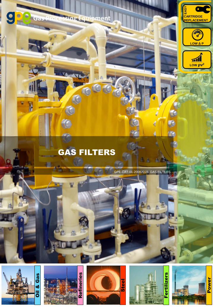
Gas Processing Equipment
GAS FILTERS
CARTRIDGE
REPLACEMENT
EA
SY
LOW Δ P
LOW ρv2
GPE-CAT-01-20082018- GAS FILTERS
Oil &
G
as
Re
fin
erie
s
Ste
el
Fe
rtilize
rs
Pow
er
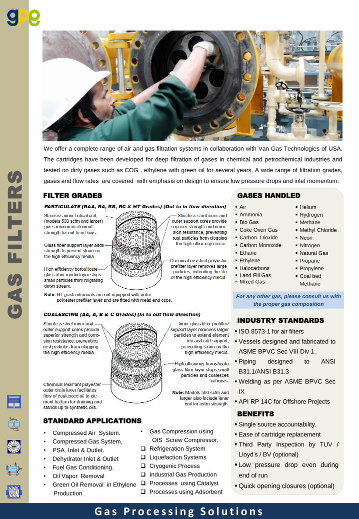
FILTER GRADES
We offer a complete range of air and gas filtration systems in collaboration with Van Gas Technologies of USA.
The cartridges have been developed for deep filtration of gases in chemical and petrochemical industries and
tested on dirty gases such as COG , ethylene with green oil for several years. A wide range of filtration grades,
gases and flow rates are covered with emphasis on design to ensure low pressure drops and inlet momentum.
• Compressed Air System.
• Compressed Gas System.
• PSA Inlet & Outlet.
• Dehydrator Inlet & Outlet
• Fuel Gas Conditioning.
• Oil Vapor Removal
• Green Oil Removal in Ethylene
Production
• Gas Compression using
OIS Screw Compressor.
Refrigeration System
Liquefaction Systems
Cryogenic Process
Industrial Gas Production
Processes using Catalyst
Processes using Adsorbent
STANDARD APPLICATIONS Single source accountability.
Ease of cartridge replacement
Third Party Inspection by TUV /
Lloyd’s / BV (optional)
Low pressure drop even during
end of run
Quick opening closures (optional)
BENEFITS
GASES HANDLED
Air
Ammonia
Bio Gas
Coke Oven Gas
Carbon Dioxide
Carbon Monoxide
Ethane
Ethylene
Halocarbons
Land Fill Gas
Mixed Gas
Helium
Hydrogen
Methane
Methyl Chloride
Neon
Nitrogen
Natural Gas
Propane
Propylene
Coal bed
Methane
For any other gas, please consult us with
the proper gas composition
ISO 8573-1 for air filters
Vessels designed and fabricated to
ASME BPVC Sec VIII Div 1.
Piping designed to ANSI
B31.1/ANSI B31.3
Welding as per ASME BPVC Sec
IX
API RP 14C for Offshore Projects
INDUSTRY STANDARDS
G a s P r o c e s s i n g S o l u t i o n s
GA
S F
IL
TE
RS
FILT
ER
S
TY
LE
A
ND
R
AN
GE
G a s P r o c e s s i n g S o l u t i o n s
Gra
de
Purpose
Pa
rtic
le
Rem
ova
l
µ
Efficiency % Max. Oil
Carry
Over
ppm w/w
Ma
x T
em
p.
0C
Cle
an
Dry
Pr.
Dro
p
ba
rd
We
t C
lea
n
Pr.
Dro
p
ba
rd
Flo
w
Dir
ec
tio
n
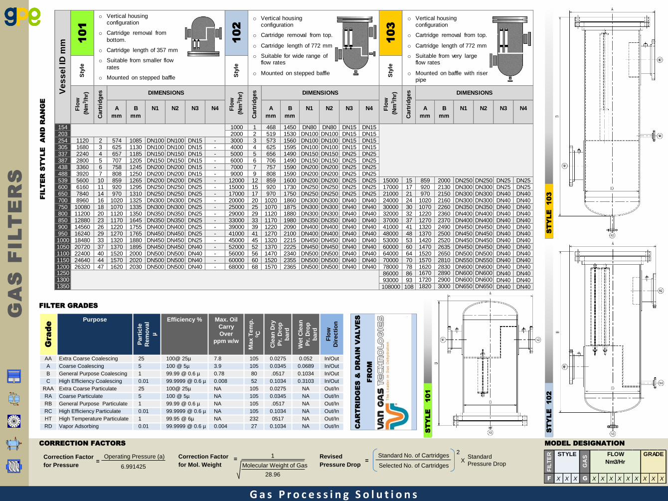
AA Extra Coarse Coalescing 25 100@ 25µ 7.8 105 0.0275 0.052 In/Out
A Coarse Coalescing 5 100 @ 5µ 3.9 105 0.0345 0.0689 In/Out
B General Purpose Coalescing 1 99.99 @ 0.6 µ 0.78 80 .0517 0.1034 In/Out
C High Efficiency Coalescing 0.01 99.9999 @ 0.6 µ 0.008 52 0.1034 0.3103 In/Out
RAA Extra Coarse Particulate 25 100@ 25µ NA 105 0.0275 NA Out/In
RA Coarse Particulate 5 100 @ 5µ NA 105 0.0345 NA Out/In
RB General Purpose Particulate 1 99.99 @ 0.6 µ NA 105 .0517 NA Out/In
RC High Efficiency Particulate 0.01 99.9999 @ 0.6 µ NA 105 0.1034 NA Out/In
HT High Temperature Particulate 1 99.95 @ 6µ NA 232 0517 NA Out/In
RD Vapor Adsorbing 0.01 99.9999 @ 0.6 µ 0.004 27 0.1034 NA Out/In
FILTER GRADES
CORRECTION FACTORS
Revised
Pressure Drop
Standard No. of Cartridges
Selected No. of Cartridges
Standard
Pressure Drop
2
X = Correction Factor
for Mol. Weight
1
Molecular Weight of Gas
28.96
= Correction Factor
for Pressure
Operating Pressure (a)
6.991425 =
ST
YLE
101
ST
YLE
102
ST
YLE
103
MODEL DESIGNATION
CA
RT
RID
GE
S &
D
RA
IN
V
ALV
ES
FR
OM
GA
S F
IL
TE
RS
A
mm
B
mm
N1 N2 N3 N4 A
mm
B
mm
N1 N2 N3 N4 A
mm
B
mm
N1 N2 N3 N4
154 1000 1 468 1450 DN80 DN80 DN15 DN15203 2000 2 519 1530 DN100 DN100 DN15 DN15254 1120 2 574 1085 DN100 DN100 DN15 - 3000 3 573 1560 DN100 DN100 DN15 DN15305 1680 3 625 1130 DN100 DN100 DN15 - 4000 4 625 1595 DN100 DN100 DN15 DN15337 2240 4 657 1185 DN150 DN150 DN15 - 5000 5 656 1490 DN150 DN150 DN25 DN25387 2800 5 707 1205 DN150 DN150 DN15 - 6000 6 706 1490 DN150 DN150 DN25 DN25438 3360 6 758 1245 DN200 DN200 DN15 - 7000 7 757 1590 DN200 DN200 DN25 DN25488 3920 7 808 1250 DN200 DN200 DN15 - 9000 9 808 1590 DN200 DN200 DN25 DN25539 5600 10 859 1265 DN200 DN200 DN25 - 12000 12 859 1600 DN200 DN200 DN25 DN25 15000 15 859 2000 DN250 DN250 DN25 DN25600 6160 11 920 1295 DN250 DN250 DN25 - 15000 15 920 1730 DN250 DN250 DN25 DN25 17000 17 920 2130 DN300 DN300 DN25 DN25650 7840 14 970 1310 DN250 DN250 DN25 - 17000 17 970 1750 DN250 DN250 DN25 DN25 21000 21 970 2150 DN300 DN300 DN40 DN40700 8960 16 1020 1325 DN300 DN300 DN25 - 20000 20 1020 1860 DN300 DN300 DN40 DN40 24000 24 1020 2160 DN300 DN300 DN40 DN40750 10080 18 1070 1335 DN300 DN300 DN25 - 25000 25 1070 1875 DN300 DN300 DN40 DN40 30000 30 1070 2260 DN350 DN350 DN40 DN40800 11200 20 1120 1350 DN350 DN350 DN25 - 29000 29 1120 1880 DN300 DN300 DN40 DN40 32000 32 1220 2360 DN400 DN400 DN40 DN40850 12880 23 1170 1645 DN350 DN350 DN25 - 33000 33 1170 1980 DN350 DN350 DN40 DN40 37000 37 1270 2370 DN400 DN400 DN40 DN40900 14560 26 1220 1755 DN400 DN400 DN25 - 39000 39 1220 2090 DN400 DN400 DN40 DN40 41000 41 1320 2490 DN450 DN450 DN40 DN40950 16240 29 1270 1765 DN450 DN450 DN25 - 41000 41 1270 2100 DN400 DN400 DN40 DN40 48000 48 1370 2500 DN450 DN450 DN40 DN401000 18480 33 1320 1880 DN450 DN450 DN25 - 45000 45 1320 2215 DN450 DN450 DN40 DN40 53000 53 1420 2520 DN450 DN450 DN40 DN401050 20720 37 1370 1895 DN450 DN450 DN40 - 52000 52 1370 2225 DN450 DN450 DN40 DN40 60000 60 1470 2635 DN450 DN450 DN40 DN401100 22400 40 1520 2000 DN500 DN500 DN40 - 56000 56 1470 2340 DN500 DN500 DN40 DN40 64000 64 1520 2650 DN500 DN500 DN40 DN401150 24640 44 1570 2020 DN500 DN500 DN40 - 60000 60 1520 2355 DN500 DN500 DN40 DN40 70000 70 1570 2810 DN550 DN550 DN40 DN401200 26320 47 1620 2030 DN500 DN500 DN40 - 68000 68 1570 2365 DN500 DN500 DN40 DN40 78000 78 1620 2830 DN600 DN600 DN40 DN401250 86000 86 1670 2890 DN600 DN600 DN40 DN401300 93000 93 1720 2900 DN600 DN600 DN40 DN401350 108000 108 1820 3000 DN650 DN650 DN40 DN40
Ve
ss
el ID
mm 1
01
102
Sty
le
Sty
le
Flo
w
(N
m3/h
r)
Cart
rid
ges DIMENSIONS
Cart
rid
ges DIMENSIONS
Flo
w
(N
m3/h
r)
Cart
rid
ges DIMENSIONS
Flo
w
(N
m3/h
r)S
tyle
103
o Vertical housing configuration
o Cartridge removal from
bottom.
o Cartridge length of 357 mm
o Suitable from smaller flow
rates
o Mounted on stepped baffle
o Vertical housing configuration
o Cartridge removal from top.
o Cartridge length of 772 mm
o Suitable for wide range of flow rates
o Mounted on stepped baffle
o Vertical housing configuration
o Cartridge removal from top.
o Cartridge length of 772 mm
o Suitable from very large flow rates
o Mounted on baffle with riser pipe
FIL
TE
R
GA
S
F X X X G X X X X X X X X X
GRADEFLOW
Nm3/Hr
STYLE
G a s P r o c e s s i n g S o l u t i o n s
GA
S F
IL
TE
RS
Feed
Stock
Coalescing
Filter
Furnace
Quench
Tower
Quench
Tower
Ethylene
Dryer
Compressor
Caustic
Wash
Condensate
Removal
ChillerMist
Pad
Ethylene
Fractionator
Gas To Gas
Cooler
Gas from
Compressor
Chiller
Coalescing
Filter
Vapour
Adsorbing
To Process
Recycle Gas
from Process
Recycle Gas
CompressorParticulate
Filter
Back to
Process
Multi
Cyclone
Dra
in
Turbine
Inlet Gas
Filter
Separator
Pressure
Reduction
Electric/Fired/
Water Bath
Heater
Multi
Cyclone
Dra
in
Turbine
Inlet Gas
Filter
Separator
Electric/Fired/
Water Bath
Heater
Filter
Compressor
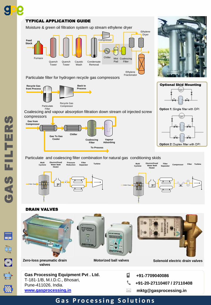
Particulate filter for hydrogen recycle gas compressors
Particulate and coalescing filter combination for natural gas conditioning skids
Coalescing and vapour absorption filtration down stream oil injected screw
compressors
Moisture & green oil filtration system up stream ethylene dryer
TYPICAL APPLICATION GUIDE
DRAIN VALVES
Zero-loss pneumatic drain
valves
Motorized ball valves Solenoid electric drain valves
Gas Processing Equipment Pvt . Ltd.
T-181-1/B, M.I.D.C., Bhosari,
Pune-411026, India.
www.gasprocessing.in
+91-7709040086
+91-20-27110407 / 27110408
Top Related