


γλώσσες
Σελίδες
Νομικός

Focusing characteristics of a 4π parabolic mirror light-matter interface
Lucas Alber,1, 2, ∗ Martin Fischer,1, 2, ∗ Marianne Bader,1, 2
Klaus Mantel,1 Markus Sondermann,1, 2 and Gerd Leuchs1, 2, 3
1Max Planck Institute for the Science of Light,Guenther-Scharowsky-Str. 1/ building 24, 91058 Erlangen, Germany†
2Friedrich-Alexander-Universitat Erlangen-Nurnberg (FAU),Department of Physics, Staudtstr. 7/B2, 91058 Erlangen, Germany
3Department of Physics, University of Ottawa, Ottawa, Ont. K1N 6N5, Canada
Focusing with a 4π parabolic mirror allows for concentrating light from nearly the complete solidangle, whereas focusing with a single microscope objective limits the angle cone used for focusingto half solid angle at maximum. Increasing the solid angle by using deep parabolic mirrors comesat the cost of adding more complexity to the mirror’s fabrication process and might introduceerrors that reduce the focusing quality. To determine these errors, we experimentally examine thefocusing properties of a 4π parabolic mirror that was produced by single-point diamond turning. Theproperties are characterized with a single 174Yb+ ion as a mobile point scatterer. The ion is trappedin a vacuum environment with a movable high optical access Paul trap. We demonstrate an effectivefocal spot size of 209 nm in lateral and 551 nm in axial direction. Such tight focusing allows us tobuild an efficient light-matter interface. Our findings agree with numerical simulations incorporatinga finite ion temperature and interferometrically measured wavefront aberrations induced by theparabolic mirror. We point at further technological improvements and discuss the general scope ofapplications of a 4π parabolic mirror.
I. INTRODUCTION
Free space interaction between light and matter isincorporated as a key technology in many fields inmodern science. The efficiency of interaction influ-ences measurements and applications ranging fromvarious kinds of fundamental research to industrialapplications. New innovations and new types of highprecision measurements can be triggered by improv-ing the tools needed for a light-matter interface. Toachieve high interaction probability with a focusedlight field in free space, an experimental scheme us-ing parabolic mirrors for focusing onto single atomshas been developed in recent years [1–3]. This schemerelies on mode matching of the focused radiation toan electric dipole mode (cf. Ref. [4] and citationstherein).
Focusing in free-space experiments is usually donewith state-of-the-art lens based imaging systems [5–8].Single lenses, however, suffer from inherent drawbackslike dispersion induced chromatic aberrations, opticalaberrations, and auto-fluorescence, respectively. Mostof these limitations can be corrected to a high de-gree by precisely assembling several coated lenses in alens-system, e.g. in a high numerical aperture (NA)objective. Although solving some problems, multi-lens-systems induce new problems such as short work-ing distances, low transmission for parts of the opti-cal spectrum, the need for immersion fluids, and highcosts, respectively. Therefore, multi-lens systems areoften application specific providing best performanceonly for the demands that are most important for theapplication.
∗ These authors contributed equally to this work.† [email protected]
Mirror based objectives are an alternative to lens-based systems and can overcome some of these prob-lems. The improvement is based on a mirror’s in-herent property of being free from chromatic aberra-tions. The nearly wavelength independent behavioralso leads to a homogeneous reflectivity for a largespectral window. Comparing the reflectivity of mir-rors to the transmission of lens based objectives, mir-rors can sometimes also surpass lens-based systems.But surprisingly, they are rarely used when high in-teraction efficiency is required. This lack in applica-tion may be due to the fact that reflecting imagingsystems, like the Cassegrain reflector, cannot providea high NA. A high NA is however needed for matchingthe emission pattern of a dipole, which spans over theentire solid angle. The limitation in NA consequentlyconstitutes a limitation in the maximum achievablelight-matter coupling efficiency.
High NA parabolic mirrors (NA = 0.999) havemeanwhile been successfully applied as objectives inconfocal microscopy [9, 10], demonstrating the poten-tial for imaging applications. The parabolic mirror(PM) is a single optical element that, in theory, cancover nearly the complete 4π solid angle for tight fo-cusing [11]. In this article we report on the detailedcharacterization of such a 4π parabolic mirror (4π-PM), in which we sample the focal intensity distribu-tion with a single 174Yb+ ion, trapped in a stylus likemovable Paul trap [12].
In contrast to our previous studies [13], we measurethe response of the ion at a wavelength different tothe one used for excitation. This approach is standardin fluorescence microscopy and has also been used inexperiments with trapped ions [14]. It renders unnec-essary a spatial separation of focused light and lightscattered by the ion, thus lifting the limitation of fo-cusing only from half solid angle as in Ref. [13]. How-ever, we will find below that by using the solid angle
arX
iv:1
609.
0688
4v2
[qu
ant-
ph]
28
Feb
2017
2
provided by our 4π-PM the measured effective excita-tion point spread function (PSF ) is worse when usingthe full mirror as compared to focusing from only halfsolid angle. As outlined below, this is not a generalrestriction but specific to the aberrations of the mirrorused in our experiments. It is a challenge to determinethe aberrations of such a deep parabolic mirror [15]and we discovered the full extent of these aberrationsonly when scanning the 3D field distribution with thesingle ion, revealing an error in the earlier interfero-metric measurements. Here, we present a reasonableagreement of the experiments with results of simula-tions incorporating a finite ion temperature and newinterferometrically measured wavefront aberrations ofthe parabolic mirror itself.
Despite of these aberrations, the efficiency obtainedhere for coupling the focused light to the linear dipoletransition of the 174Yb+ ion is better than reportedpreviously [13], using the full mirror as well as focus-ing from half solid angle. As a further improvement incomparison to Ref. [13] we keep the excitation of theion well below saturation making sure that the sizeof the ion’s wave function stays approximately con-stant as much as possible. All in all, the ion consti-tutes a nanoscopic probe with well defined propertiesthroughout the measurement range.
In the concluding discussion of this paper, theparabolic mirror is compared to other high NA focus-ing tools, especially to lens-based 4π microscopes. Itspossible field of application is discussed and furtherimprovements to the existing set-up are proposed.
II. SETUP AND EXPERIMENT
Our main experimental intention is to focus light toa minimal spot size in all spatial directions simultane-ously. The highest electric energy density that can berealized with any focusing optics is created by an elec-tric dipole wave [16]. We therefore choose this type ofspatial mode in our experiment. The electric dipolewave is created by first converting a linear polarizedGaussian beam into a radially polarized donut modevia a segmented half-wave plate (B- Halle) [17, 18].Second, the radially polarized donut mode is focusedwith a parabolic mirror onto the trapped ion. This,in theory, enables us to convert approximately 91 %of the donut mode into a linear dipole mode [19]. Theconversion efficiency is limited since the donut mode isonly approximating the ideal spatial mode that is nec-essary to create a purely linear dipole mode [2, 20] bybeing focused with the parabolic mirror. The donutmode, however, yields the experimental advantage ofbeing propagation invariant and comparably easy togenerate.
Our focusing tool, the parabolic mirror, is made ofdiamond turned aluminum (Fraunhofer Institute forApplied Optics and Precision Engineering, Jena) witha reflectivity of 64 % for the incident mode at a wave-length of λexc = 369.5 nm. Its geometry has a focallength of 2.1 mm and an outer aperture of 20 mm in
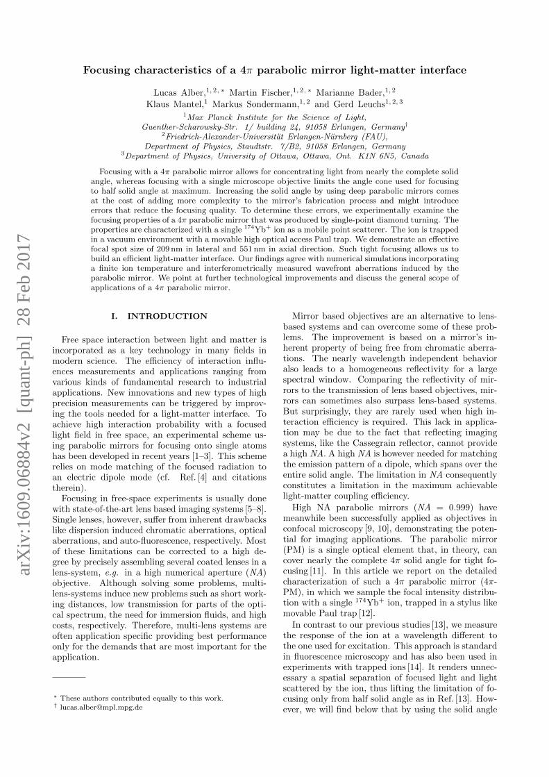
FIG. 1. Optical set-up of the experiment and relevantenergy levels of 174Yb+. The cooling laser (blue) and therepump laser (red) are focused onto the ion through a holeat the backside of the parabolic mirror. AOM - acoustooptical modulator, DM - dichroic mirror, F - clean up fil-ter, 4π-PM - 4π parabolic mirror, PMT - photo multipliertube, SHWP - segmented half-wave plate.
diameter. In total, the geometry covers 81 % of thecomplete solid angle. This fraction corresponds to94 % of the solid angle that is relevant for couplingto a linear dipole oriented along the axis of symme-try [11, 19]. Furthermore, the mirror has three boresnear its vertex: two bores with a diameter of 0.5 mmfor dispensing neutral atoms and for illuminating theion with additional laser beams, respectively; and onebore with a diameter of 1.5 mm for the ion trap it-self. The ion trap is a Stylus-like Paul trap similarto [12] with high optical access. The trap is mountedon a movable xyz piezo translation stage (PIHera P-622K058, Physik Instrumente) that is used for mea-suring the effective excitation PSF. The effective ex-citation PSF is defined as the convolution of the focalintensity distribution with the spatial extent of theion.
We measure the effective excitation PSF by prob-ing the focal spot at different positions. In order todo so, we use the translation stage to scan the ionthrough the focal spot with an increment of 25 nm.At each position, the incoming dipole mode excitesthe S1/2 - P1/2 transition that has a wavelength ofλexc = 369.5 nm and a transition linewidth of Γ/2π =19.6 MHz [21]. The relevant energy levels of 174Yb+
are shown in figure 1. We weakly drive this transi-tion such that the probability for exciting the ion intothe P1/2 state is proportional to the electric energydensity at any point in the focal area. During thesemeasurements, the ion is Doppler cooled by the fo-cused donut mode. Hence, the detuning of this moderelative to the S1/2 - P1/2 transition and its power de-termine the temperature of the ion, see appendix forfurther details.
Since we excite the ion from the complete solid anglethat is covered by the 4π parabolic mirror and sincealmost all excitation light is reflected into the detec-tion beam path by the parabolic mirror, we cannotdirectly detect the fluorescent response of the ion atthe same wavelength. Instead, we detect photons at awavelength of λdet = 297.1 nm allowing us to indepen-
3
Transition Branching ratio Decay rate [Γ/2π]2P1/2 - 2S1/2 99.5 % 19.6 MHz2P1/2 - 2D3/2 0.5 %3D[3/2]1/2 - 2D3/2 1.8 % 4.2 MHz3D[3/2]1/2 - 2S1/2 98.2 %2D3/2 - 2S1/2 3 Hz
TABLE I. Branching ratios and decay rates for the rele-vant transitions of 174Yb+ taken from [21, 22] and citationstherein.
dently focus and detect from nearly the complete solidangle. Photons at the detection wavelength λdet areemitted during the spontaneous D[3/2]1/2 - S1/2 de-
cay [21]. The D[3/2]1/2 level is populated when the ion
spontaneously decays from the excited P1/2 state intothe metastable D3/2 state (branching ratio β = 0.5 %,lifetime of 52 ms [22], see table I). From this state, weoptically pump the ion into the D[3/2]1/2 state by sat-
urating the D3/2 - D[3/2]1/2 transition with a strong
laser field at a wavelength of 935.2 nm (DL-100, Top-tica Photonics). The upper state of this transitiondecays to the S1/2 ground state with a probability of98 % [21]. The infrared laser is co-aligned with a sec-ond laser at the excitation wavelength λexc (TA-SHGpro, Toptica Photonics) and both are sent through thefocus of the parabolic mirror via one of its backsidebores (see figure 1). The second laser at the excitationwavelength λexc is used for ionization.
The emitted fluorescent photons at the detectionwavelength λdet are out-coupled from the excitationbeam path via a dichroic mirror (FF310-Di01, Sem-rock) and two clean up filters (FF01-292/27-25, Sem-rock). Afterwards, we detect them with a photomulti-plier tube in Geiger mode operation (MP-942, PerkinElmer) that has a remaining underground/dark countrate of 10 - 20 cps. The overall detection efficiencyηdet at the detection wavelength λdet was measuredvia pulsed excitation and amounts to ηdet ≈ 1.4 % (seeappendix). The detection efficiency is needed for thedetermination of the coupling efficiency to the trappedion.
Based on the atomic decay rate on the detectedtransition, the total photon emission rate would beapproximately R = β Γ
212 = 154 kcps for S = 1 (see
equation 1). Taking into account the finite detectionefficiency, we would expect to measure approximatelyRdet = ηdet 154 kcps = 2160 cps.
The coupling efficiency is measured by recording thedetection count rate Rdet as a function of the excita-tion power Pexc. Analyzing the four-level quantummaster equation we find that both quantities are pro-portional to each other in the limit of strong repump-ing powers and saturation parameters S 1. Thelatter condition is met by keeping S ≤ 0.1 in our mea-surements. This also ensures that the spatial extentof the ion is approximately constant throughout themeasurement, see appendix. The dependence of Rdet
-1000 -500 0 500 10000
120
240
360
480
Coun
ts[c
ps]
Z [nm]
-600 -300 0 300 6000
120
240
360
480
Coun
ts[c
ps]
Y [nm]-600 -300 0 300 600
0
120
240
360
480
Coun
ts[c
ps]
X [nm]
675
0
370 nm
370 nm 370 nm
(a) (b)
(c) (d)
(e) (f)
xy
xz
zy
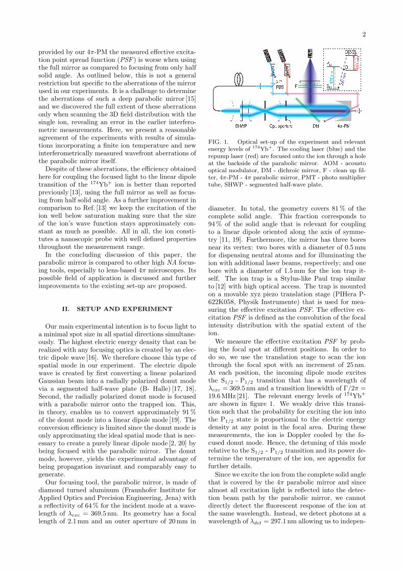
FIG. 2. Effective excitation PSF in the xy (a), zy (b), andxz (c) plane when illuminating the full solid angle coveredby the 4π-PM. The corresponding line profiles through thecenter of the focus are shown in (d-f). They are overlayedto the line profiles resulting from numerical simulations(red)
for varying excitation power is given by
Rdet = ηdet βΓ
2
S
S + 1
= ηdet βΓ
2
GPexc/PsatGPexc/Psat + 1
(1)
with S denoting the saturation parameter, and G thecoupling efficiency, respectively. The saturation powerPsat is defined as Psat = 3 · hc
λexcΓ8 (1 + 4(∆/Γ)2).
The factor 3 accounts for the fact that we are notdriving a closed linear-dipole transition but a J=1/2↔ J=1/2 one. The relation between saturation pa-rameter, saturation power and coupling efficiency isS = GPexc/Psat [13]. ∆ is the detuning of the excita-tion laser from the S1/2 - P1/2 resonance. The formulafor the detection count rate enables us to determinethe coupling efficiency by curve fitting of our mea-sured data for Rdet as a function of Pexc. For thecurve fitting, all parameters except the coupling effi-ciency are kept constant. During the measurement ofthe coupling efficiency, we position the ion exactly inthe maximum of the excitation PSF, i.e. we measurethe maximum coupling efficiency obtainable in the fo-cal region under the current experimental conditions.
III. RESULTS
The experimental results for the effective excitationPSF are shown in figure 2. We measure a spot sizeof 237 ± 10 nm (FWHM ) in the lateral direction (a,e, f). In the axial direction (b - d), however, thefocal peak is broadened due to optical aberrations.The influence of the aberrations is reduced, when we
4
-750 -500 -250 0 250 500 7500
30
60
90
120Co
unts
[cps
]
Z [nm]
-500 -250 0 250 5000
30
60
90
120Co
unts
[cps
]
Y [nm]-500 -250 0 250 500
0
30
60
90
120
Coun
ts[c
ps]
X [nm]
170
0
370 nm
370 nm 370 nm
(a) (b)
(c) (d)
(e) (f)
xy
xz
zy
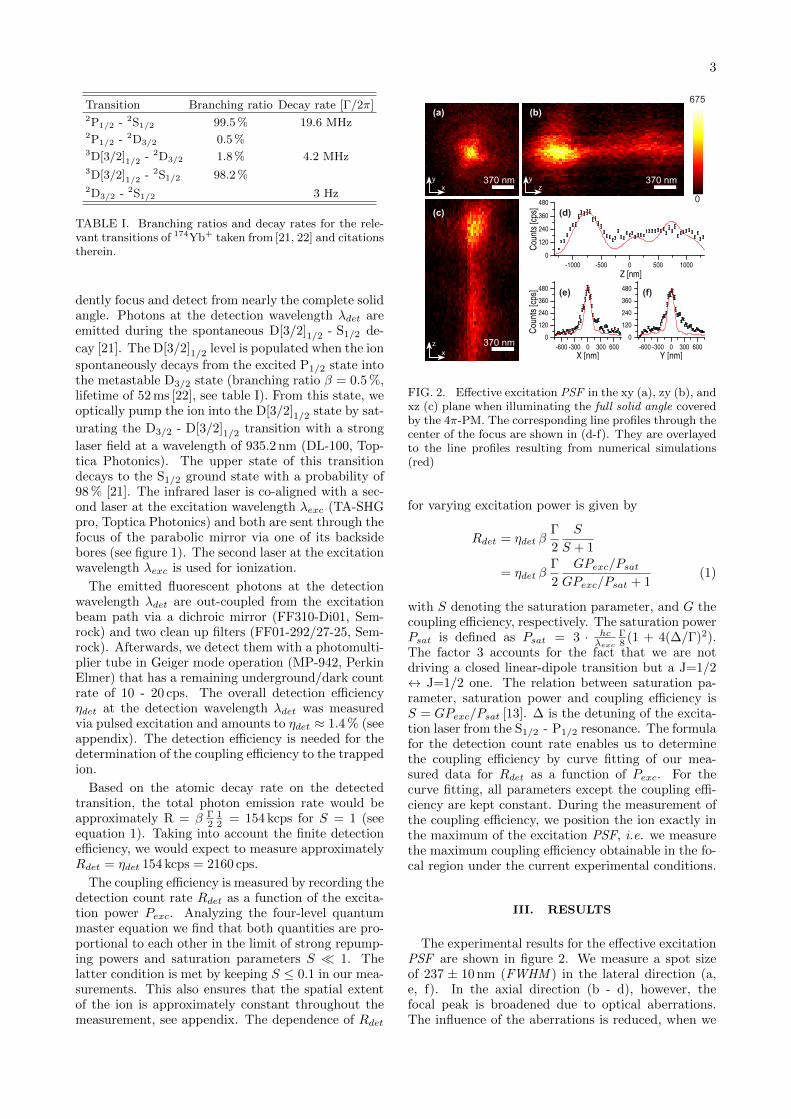
FIG. 3. Effective excitation PSF similar to figure 2 butfor illuminating half of the solid angle of the 4π-PM. Thisis accomplished by using the optional aperture shown infigure 1.
limit the front aperture of the 4π-PM to half solidangle (figure 3). The reduced aperture results in alateral width of 209 ± 20 nm and an axial width of551 ± 27 nm. These values include the influence ofthe finite spatial extent of the trapped ion (see ap-pendix). In the Doppler limit, this extent is approxi-mately 140 nm in lateral and 80 nm in axial directionconsidering the trap frequencies ωlateral/2π ∼= 490 kHzand ωaxial/2π ∼= 1025 kHz, respectively, and a detun-ing from resonance of about 14.1 MHz.
To determine the minimal contribution of the ion-size to the focal broadening when Doppler cooling,we simulate the excitation PSF based on a general-ization of the method presented in [23]. Our simula-tion also includes the aberrations of the parabolic mir-ror which were measured interferometrically before-hand [15]. The intensity distributions resulting fromsimulations only accounting for mirror aberrations aresubsequently convolved with the spatial extent of theion to achieve the effective excitation PSF.
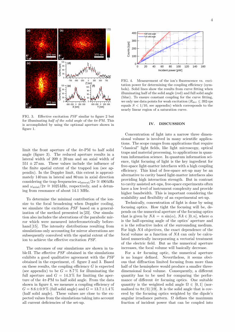
The outcomes of our simulations are shown in ta-ble II. The effective PSF obtained in the simulationsexhibits a good qualitative agreement with the PSFobtained in the experiment, cf. figure 2 and 3. Basedon these results, the coupling efficiency G is expected(see appendix) to be G = 8.7 % for illuminating thefull aperture and G = 14.3 % for limiting the aper-ture of the 4π-PM to half solid angle. From the datashown in figure 4, we measure a coupling efficiency ofG = 8.6±0.9 % (full solid angle) and G = 13.7±1.4 %(half solid angle). These values are close to the ex-pected values from the simulations taking into accountall current deficiencies of the set-up.
0 2 0 4 0 6 0 8 0 1 0 0 1 2 0 1 4 0 1 6 00
1 0 0
2 0 0
3 0 0
4 0 0 H a l f s o l i d a n g l e
F u l l s o l i d a n g l e
Coun
ts [cp
s]
I n c i d e n t p o w e r [ p W ]
FIG. 4. Measurement of the ion’s fluorescence vs. exci-tation power for determining the coupling efficiency (sym-bols). Solid lines show the results from curve fitting whenilluminating half of the solid angle (red) and full solid angle(blue). To ensure constant coupling for the curve fitting,we only use data points for weak excitation (Rdet ≤ 392 cpsequals S < 1/10, see appendix) which corresponds to thenearly linear region of a saturation curve.
IV. DISCUSSION
Concentration of light into a narrow three dimen-sional volume is involved in many scientific applica-tions. The scope ranges from applications that require”classical” light fields, like light microscopy, opticaltraps and material processing, to applications in quan-tum information science. In quantum information sci-ence, tight focusing of light is the key ingredient forfree-space light-matter interfaces with a high couplingefficiency. This kind of free-space set-up may be analternative to cavity based light-matter interfaces alsoproviding high interaction strength. But in contrastto cavity assisted set-ups, free-space experiments oftenhave a low level of instrument complexity and providehigher bandwidth. This is important considering thescalability and flexibility of an experimental set-up.
Technically, concentration of light is done by usingfocusing optics. How tight the focusing will be, de-pends on the numerical aperture of the focusing opticsthat is given by NA = n sin(α), NA ∈ [0, n], where αis the half-opening angle of the optics’ aperture andn is the refractive index of the surrounding medium.For high NA objectives, the exact dependence of thefocal volume as a function of NA can only be calcu-lated numerically incorporating a vectorial treatmentof the electric field. But as the numerical apertureincreases, the focal volume will basically decrease.
For a 4π focusing optic, the numerical apertureis no longer defined. Nevertheless, it seems obvi-ous that diffraction limited focusing from more thanhalf of the hemisphere would produce a smaller three-dimensional focal volume. Consequently, a differentquantity has to be used for comparing the perfor-mance of different 4π focusing optics. One suitablequantity is the weighted solid angle Ω ∈ [0, 1] (nor-malized to 8π/3) [19]. It is the solid angle that is cov-ered by the focusing optics weighted by the dipole’sangular irradiance pattern. Ω defines the maximumfraction of incident power that can be coupled into
5
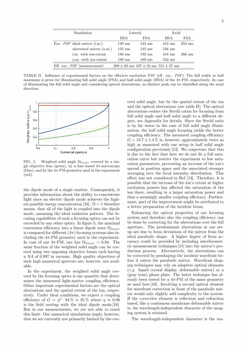
Simulation Lateral Axial
HSA FSA HSA FSA
Exc. PSF ideal mirror (i.m.) 139 nm 142 nm 412 nm 253 nm
aberrated mirror (a.m.) 135 nm 135 nm 536 nm
i.m. with ion-extent 189 nm 192 nm 418 nm 266 nm
a.m. with ion-extent 189 nm 189 nm 542 nm
Eff. exc. PSF (measurement) 209 ± 20 nm 237 ± 10 nm 551 ± 27 nm
TABLE II. Influence of experimental factors on the effective excitation PSF (eff. exc. PSF ). The full width at halfmaximum is given for illuminating full solid angle (FSA) and half solid angle (HSA) of the 4π-PM, respectively. In caseof illuminating the full solid angle and considering optical aberrations, no distinct peak can be identified along the axialdirection.
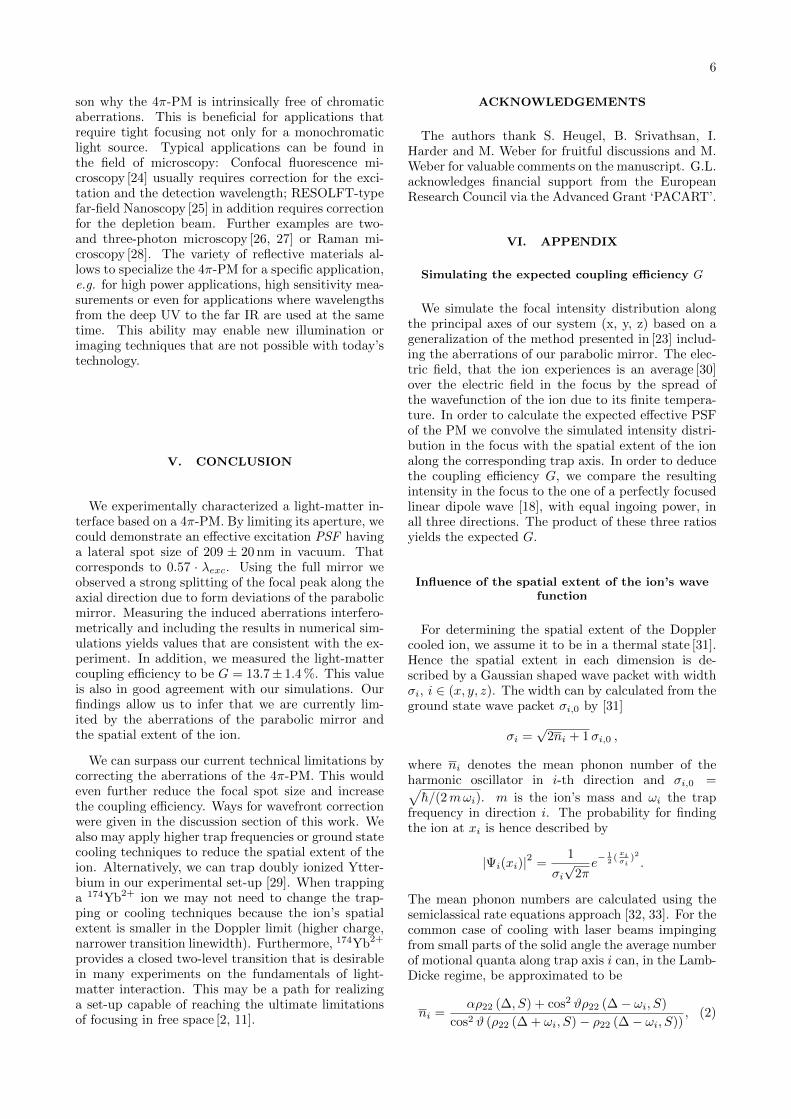
FIG. 5. Weighted solid angle Ωlinear covered by a sin-gle objective lens (green), by a lens based 4π-microscope(blue), and by the 4π-PM geometry used in the experiment(red).
the dipole mode of a single emitter. Consequently, itprovides information about the ability to concentratelight since an electric dipole mode achieves the high-est possible energy concentration [16]. Ω = 1 thereforemeans, that all of the light is coupled into the dipolemode, assuming the ideal radiation pattern. The fo-cusing capabilities of such a focusing optics can not beexceeded by any other optics. In figure 5, the maximalconversion efficiency into a linear dipole wave Ωlinearis compared for different (4π) focusing systems also in-cluding the 4π-PM geometry used in the experiment.In case of our 4π-PM, one has Ωlinear = 0.94. Thesame fraction of the weighted solid angle can be cov-ered using two opposing objective lenses each havinga NA of 0.997 in vacuum. High quality objectives ofsuch high numerical aperture are, however, not avail-able.
In the experiment, the weighted solid angle cov-ered by the focusing optics is one quantity that deter-mines the measured light-matter coupling efficiency.Other important experimental factors are the opticalaberrations and the spatial extent of the ion, respec-tively. Under ideal conditions, we expect a couplingefficiency of G = η2 · 94 % ≈ 91 % where η ≈ 0.98is the field overlap with the ideal dipole mode [18].But in our measurements, we are not able to reachthis limit. Our numerical simulations imply, however,that we are currently not primarily limited by the cov-
ered solid angle, but by the spatial extent of the ionand the optical aberrations (see table II). The opticalaberrations reduce the Strehl ratios for focusing fromfull solid angle and half solid angle to a different de-gree, see Appendix for details. Since the Strehl ratiois by far worse in the case of full solid angle illumi-nation, the half solid angle focusing yields the bettercoupling efficiency. The measured coupling efficiencyG = 13.7± 1.4 % is, however, approximately twice ashigh as measured with our setup in half solid angleconfiguration previously [13]. We conjecture that thisis due to the fact that here we do not fit a full satu-ration curve but restrict the experiment to low satu-ration parameters, preventing an increase of the ion’sspread in position space and the associated strongeraveraging over the focal intensity distribution. Thiseffect was not considered in Ref. [13]. Therefore, it ispossible that the increase of the ion’s extent at higherexcitation powers has affected the saturation of theion there, resulting in a larger saturation power andthus a seemingly smaller coupling efficiency. Further-more, part of the improvement might be attributed toa better preparation of the incident beam.
Enhancing the optical properties of our focusingsystem and therefore also the coupling efficiency canbe done by correcting for the aberrations over the fullaperture. The predominant aberrations in our set-up are due to form deviations of the mirror from theideal parabolic shape. A higher degree of form ac-curacy could be provided by including interferomet-ric measurement techniques [15] into the mirror’s pro-duction process. Alternatively, the aberrations canbe corrected by preshaping the incident wavefront be-fore it enters the parabolic mirror. Wavefront shap-ing techniques may rely on adaptive optical elements(e.g. liquid crystal display, deformable mirror) or a(gray tone) phase plate. The latter technique has al-ready been tested for a 4π-PM of the same geometryas used here [18]. Involving a second optical elementfor wavefront correction in front of the parabolic mir-ror would only slightly add complexity to the system.If the corrective element is reflection and refractionbased, like a continuous membrane deformable mirroris, the wavelength-independent character of the imag-ing system is retained.
The wavelength-independent character is the rea-
6
son why the 4π-PM is intrinsically free of chromaticaberrations. This is beneficial for applications thatrequire tight focusing not only for a monochromaticlight source. Typical applications can be found inthe field of microscopy: Confocal fluorescence mi-croscopy [24] usually requires correction for the exci-tation and the detection wavelength; RESOLFT-typefar-field Nanoscopy [25] in addition requires correctionfor the depletion beam. Further examples are two-and three-photon microscopy [26, 27] or Raman mi-croscopy [28]. The variety of reflective materials al-lows to specialize the 4π-PM for a specific application,e.g. for high power applications, high sensitivity mea-surements or even for applications where wavelengthsfrom the deep UV to the far IR are used at the sametime. This ability may enable new illumination orimaging techniques that are not possible with today’stechnology.
V. CONCLUSION
We experimentally characterized a light-matter in-terface based on a 4π-PM. By limiting its aperture, wecould demonstrate an effective excitation PSF havinga lateral spot size of 209 ± 20 nm in vacuum. Thatcorresponds to 0.57 · λexc. Using the full mirror weobserved a strong splitting of the focal peak along theaxial direction due to form deviations of the parabolicmirror. Measuring the induced aberrations interfero-metrically and including the results in numerical sim-ulations yields values that are consistent with the ex-periment. In addition, we measured the light-mattercoupling efficiency to be G = 13.7± 1.4 %. This valueis also in good agreement with our simulations. Ourfindings allow us to infer that we are currently lim-ited by the aberrations of the parabolic mirror andthe spatial extent of the ion.
We can surpass our current technical limitations bycorrecting the aberrations of the 4π-PM. This wouldeven further reduce the focal spot size and increasethe coupling efficiency. Ways for wavefront correctionwere given in the discussion section of this work. Wealso may apply higher trap frequencies or ground statecooling techniques to reduce the spatial extent of theion. Alternatively, we can trap doubly ionized Ytter-bium in our experimental set-up [29]. When trappinga 174Yb2+ ion we may not need to change the trap-ping or cooling techniques because the ion’s spatialextent is smaller in the Doppler limit (higher charge,narrower transition linewidth). Furthermore, 174Yb2+
provides a closed two-level transition that is desirablein many experiments on the fundamentals of light-matter interaction. This may be a path for realizinga set-up capable of reaching the ultimate limitationsof focusing in free space [2, 11].
ACKNOWLEDGEMENTS
The authors thank S. Heugel, B. Srivathsan, I.Harder and M. Weber for fruitful discussions and M.Weber for valuable comments on the manuscript. G.L.acknowledges financial support from the EuropeanResearch Council via the Advanced Grant ‘PACART’.
VI. APPENDIX
Simulating the expected coupling efficiency G
We simulate the focal intensity distribution alongthe principal axes of our system (x, y, z) based on ageneralization of the method presented in [23] includ-ing the aberrations of our parabolic mirror. The elec-tric field, that the ion experiences is an average [30]over the electric field in the focus by the spread ofthe wavefunction of the ion due to its finite tempera-ture. In order to calculate the expected effective PSFof the PM we convolve the simulated intensity distri-bution in the focus with the spatial extent of the ionalong the corresponding trap axis. In order to deducethe coupling efficiency G, we compare the resultingintensity in the focus to the one of a perfectly focusedlinear dipole wave [18], with equal ingoing power, inall three directions. The product of these three ratiosyields the expected G.
Influence of the spatial extent of the ion’s wavefunction
For determining the spatial extent of the Dopplercooled ion, we assume it to be in a thermal state [31].Hence the spatial extent in each dimension is de-scribed by a Gaussian shaped wave packet with widthσi, i ∈ (x, y, z). The width can by calculated from theground state wave packet σi,0 by [31]
σi =√
2ni + 1σi,0 ,
where ni denotes the mean phonon number of theharmonic oscillator in i-th direction and σi,0 =√h/(2mωi). m is the ion’s mass and ωi the trap
frequency in direction i. The probability for findingthe ion at xi is hence described by
|Ψi(xi)|2 =1
σi√
2πe− 1
2 (xiσi
)2.
The mean phonon numbers are calculated using thesemiclassical rate equations approach [32, 33]. For thecommon case of cooling with laser beams impingingfrom small parts of the solid angle the average numberof motional quanta along trap axis i can, in the Lamb-Dicke regime, be approximated to be
ni =αρ22 (∆, S) + cos2 ϑρ22 (∆− ωi, S)
cos2 ϑ (ρ22 (∆ + ωi, S)− ρ22 (∆− ωi, S)), (2)
7
where ρ22 (∆, S) = S/2(
1 + (2∆/Γ)2
+ S)
is the up-
per level population with respect to detuning and sat-uration parameter, ϑ the angle between the i-th trap
axis with the ~k-vector of the laser beam, and α afactor depending on the emission pattern of the ion.For 174Yb+ ions the emission pattern is isotropic andtherefore α = 1/3 [32]. In the case of cooling the ionwith a dipole wave, the cooling mode has a continuous
spectrum of ~k-vectors, hence the factor determiningthe overlap of the beam and the trap axis cos2 ϑ hasto be averaged over the incoming field linear dipolefield, that is has the form sin2 ϑ. With the geometryof the trap and focusing employed in the setup de-scribed here, one of the trap axes is parallel to theoptical axis of the mirror, while the other two are per-pendicular. The mean overlap for these two cases, theaveraged value of
ηax =
∫∫dϑ dϕ
3
8πsin3 ϑ cos2 (ϑ+ π/2)
ηrad =
∫∫dϑ dϕ
3
8πsin3 ϑ cos2 (ϑ+ 0) (3)
with the integration along polar angle ϕ and az-imuthal angle ϑ. This leads to a mean overlap ofηax = 1/5 of the linear dipole mode with the axialtrap axis and ηrad = 2/5 with the radial ones. Fornegligible excitation, a detuning of ∆/2π = 14.2 MHzand the trap frequencies ωx/2π = 482.6 kHz, ωy/2π =491.7 kHz, and ωz/2π = 1025 kHz, respectively, thisyields nx,y ≈ 20, and nz ≈ 14. The trap frequenciesare determined by applying an AC signal to one of thecompensation electrodes and scanning the applied fre-quency over the frequency range supposed to containthe trap frequencies while monitoring the the rate offluorescence photons.
We only use excitation powers Pexc such that S ≤1/10. This equals a detection count rate of Rdet ≤392 cps. For larger excitation powers, we expect thespatial extent of the ion to be comparable to the sizeof the focal intensity distribution and the coupling ef-ficiency to be reduced. Since n grows linearly withS [34], keeping S ≤ 0.1 ensures that the spatial extentof the ion is approximately constant over the wholemeasurement range. A change of 10 % in S corre-sponds to a change of approximately 5 % in G.
Interplay of mirror aberrations and focusinggeometry
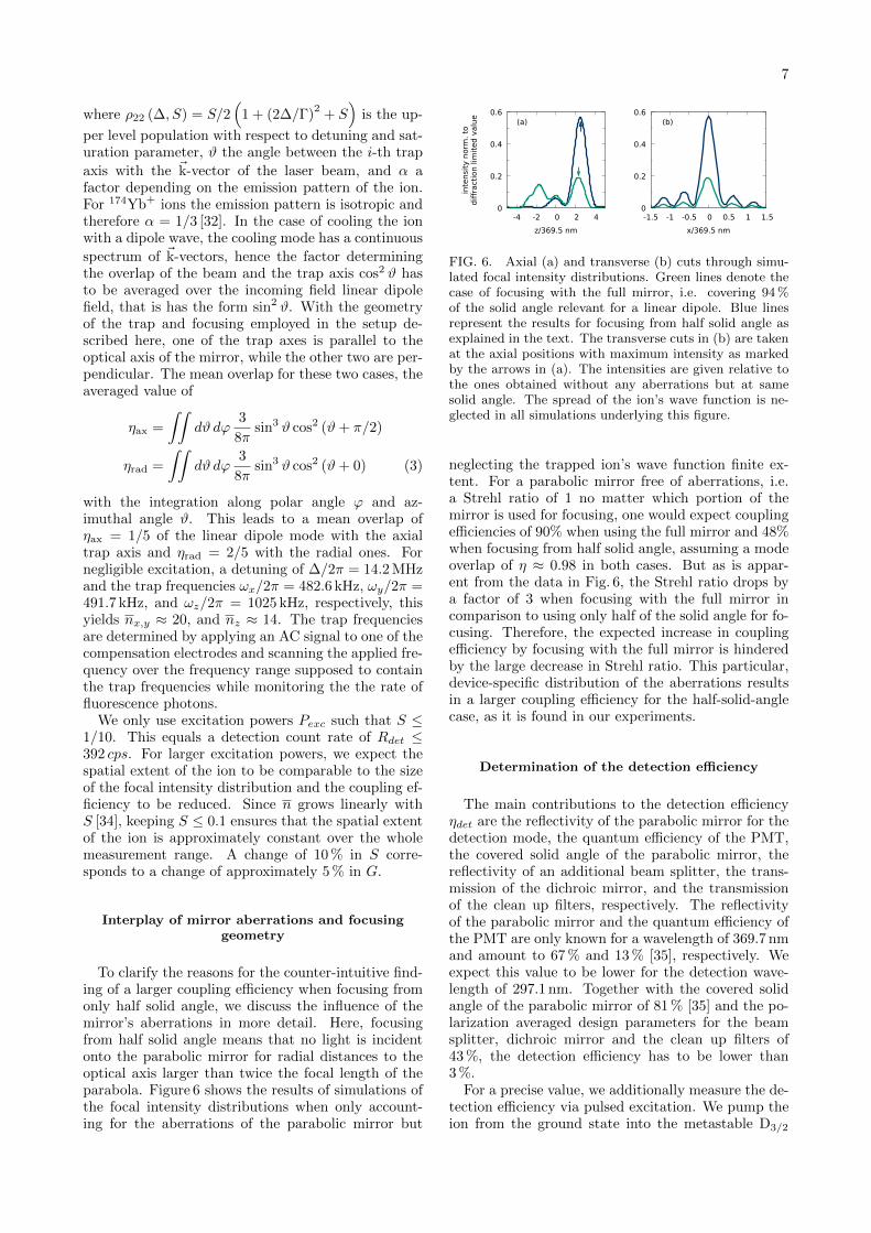
To clarify the reasons for the counter-intuitive find-ing of a larger coupling efficiency when focusing fromonly half solid angle, we discuss the influence of themirror’s aberrations in more detail. Here, focusingfrom half solid angle means that no light is incidentonto the parabolic mirror for radial distances to theoptical axis larger than twice the focal length of theparabola. Figure 6 shows the results of simulations ofthe focal intensity distributions when only account-ing for the aberrations of the parabolic mirror but
(a)
inte
nsi
ty n
orm
. to
diff
ract
ion lim
ited v
alu
e
z/369.5 nm
0
0.2
0.4
0.6
-4 -2 0 2 4
(b)
x/369.5 nm
0
0.2
0.4
0.6
-1.5 -1 -0.5 0 0.5 1 1.5
FIG. 6. Axial (a) and transverse (b) cuts through simu-lated focal intensity distributions. Green lines denote thecase of focusing with the full mirror, i.e. covering 94 %of the solid angle relevant for a linear dipole. Blue linesrepresent the results for focusing from half solid angle asexplained in the text. The transverse cuts in (b) are takenat the axial positions with maximum intensity as markedby the arrows in (a). The intensities are given relative tothe ones obtained without any aberrations but at samesolid angle. The spread of the ion’s wave function is ne-glected in all simulations underlying this figure.
neglecting the trapped ion’s wave function finite ex-tent. For a parabolic mirror free of aberrations, i.e.a Strehl ratio of 1 no matter which portion of themirror is used for focusing, one would expect couplingefficiencies of 90% when using the full mirror and 48%when focusing from half solid angle, assuming a modeoverlap of η ≈ 0.98 in both cases. But as is appar-ent from the data in Fig. 6, the Strehl ratio drops bya factor of 3 when focusing with the full mirror incomparison to using only half of the solid angle for fo-cusing. Therefore, the expected increase in couplingefficiency by focusing with the full mirror is hinderedby the large decrease in Strehl ratio. This particular,device-specific distribution of the aberrations resultsin a larger coupling efficiency for the half-solid-anglecase, as it is found in our experiments.
Determination of the detection efficiency
The main contributions to the detection efficiencyηdet are the reflectivity of the parabolic mirror for thedetection mode, the quantum efficiency of the PMT,the covered solid angle of the parabolic mirror, thereflectivity of an additional beam splitter, the trans-mission of the dichroic mirror, and the transmissionof the clean up filters, respectively. The reflectivityof the parabolic mirror and the quantum efficiency ofthe PMT are only known for a wavelength of 369.7 nmand amount to 67 % and 13 % [35], respectively. Weexpect this value to be lower for the detection wave-length of 297.1 nm. Together with the covered solidangle of the parabolic mirror of 81 % [35] and the po-larization averaged design parameters for the beamsplitter, dichroic mirror and the clean up filters of43 %, the detection efficiency has to be lower than3 %.
For a precise value, we additionally measure the de-tection efficiency via pulsed excitation. We pump theion from the ground state into the metastable D3/2
8
dark state by focusing a strong 30µs long laser pulseat a wavelength of 369.5 nm through the backsidehole of the parabolic mirror. After that, we drive theD3/2 - D[3/2]1/2 transition with a strong laser pulse
for about 30µs to ensure that the D[3/2]1/2 - S1/2 de-
cay takes place. During this decay, a photon at thedetection wavelength of 297.1 nm is emitted. While
applying the infrared light, no UV light is driving theion and only one detection photon can be emitted.For repeating the experiment with a pulse sequencerate of 10 kHz the background corrected count rateamounts to 142 cps. This yields the detection effi-ciency ηdet = 142/10000 = 1.4 %.
[1] S. Quabis, R. Dorn, M. Eberler, O. Glockl, andG. Leuchs, Optics Communications 179, 1 (2000).
[2] M. Sondermann, R. Maiwald, H. Konermann,N. Lindlein, U. Peschel, and G. Leuchs, AppliedPhysics B 89, 489 (2007).
[3] M. Stobinska, G. Alber, and G. Leuchs, EPL (Euro-physics Letters) 86, 14007 (2009).
[4] G. Leuchs and M. Sondermann, Jour-nal of Modern Optics 60, 36 (2013),http://dx.doi.org/10.1080/09500340.2012.716461.
[5] N. Piro, F. Rohde, C. Schuck, M. Almendros,J. Huwer, J. Ghosh, A. Haase, M. Hennrich, F. Dubin,and J. Eschner, Nat Phys 7, 17 (2011).
[6] M. K. Tey, G. Maslennikov, T. C. H. Liew, S. A.Aljunid, F. Huber, B. Chng, Z. Chen, V. Scarani,and C. Kurtsiefer, New Journal of Physics 11, 043011(2009).
[7] G. Wrigge, I. Gerhardt, J. Hwang, G. Zumofen, andV. Sandoghdar, Nat Phys 4, 60 (2008).
[8] D. Pinotsi and A. Imamoglu, Phys. Rev. Lett. 100,093603 (2008).
[9] A. Drechsler, M. Lieb, C. Debus, A. Meixner, andG. Tarrach, Opt. Express 9, 637 (2001).
[10] J. Stadler, C. Stanciu, C. Stupperich, and A. J.Meixner, Opt. Lett. 33, 681 (2008).
[11] N. Lindlein, R. Maiwald, H. Konermann, M. Sonder-mann, U. Peschel, and G. Leuchs, Laser Physics 17,927 (2007).
[12] R. Maiwald, D. Leibfried, J. Britton, J. C. Bergquist,G. Leuchs, and D. J. Wineland, Nature Physics 5,551 (2009).
[13] M. Fischer, M. Bader, R. Maiwald, A. Golla, M. Son-dermann, and G. Leuchs, Applied Physics B 117, 797(2014).
[14] N. M. Linke, D. T. C. Allcock, D. J. Szwer, C. J.Ballance, T. P. Harty, H. A. Janacek, D. N. Stacey,A. M. Steane, and D. M. Lucas, Applied Physics B107, 1175 (2012).
[15] G. Leuchs, K. Mantel, A. Berger, H. Konermann,M. Sondermann, U. Peschel, N. Lindlein, andJ. Schwider, Applied Optics 47, 5570 (2008).
[16] I. M. Bassett, Optica Acta: International Journal ofOptics 33, 279 (1986).
[17] S. Quabis, R. Dorn, and G. Leuchs, Applied PhysicsB 81, 597 (2005).
[18] A. Golla, B. Chalopin, M. Bader, I. Harder, K. Man-
tel, R. Maiwald, N. Lindlein, M. Sondermann,and G. Leuchs, Eur. Phys. J. D 66, 190 (2012),arXiv:1207.3215.
[19] M. Sondermann, N. Lindlein, and G. Leuchs, ArXive-prints (2008), arXiv:0811.2098 [physics.optics].
[20] G. Alber, J. Z. Bernad, M. Stobinska, L. L. Sanchez-Soto, and G. Leuchs, Phys. Rev. A 88, 023825 (2013).
[21] H. M. Meyer, M. Steiner, L. Ratschbacher, C. Zipkes,and M. Kohl, Physical Review A 85, 012502 (2012).
[22] S. Olmschenk, K. C. Younge, D. L. Moehring, D. N.Matsukevich, P. Maunz, and C. Monroe, PhysicalReview A 76, 052314 (2007).
[23] B. Richards and E. Wolf, Proceedings of the RoyalSociety of London A: Mathematical, Physical and En-gineering Sciences 253, 358 (1959).
[24] C. J. R. Sheppard and A. Choudhury, Optica Acta:International Journal of Optics 24, 1051 (1977).
[25] S. W. Hell, Science 316, 1153 (2007).[26] N. G. Horton, K. Wang, D. Kobat, C. G. Clark, F. W.
Wise, C. B. Schaffer, and C. Xu, Nature Photonics7, 205 (2013).
[27] W. Denk, J. H. Strickler, and W. W. Webb, Science248, 73 (1990).
[28] M. E. Andersen and R. Z. Muggli, An-alytical Chemistry 53, 1772 (1981),http://dx.doi.org/10.1021/ac00235a013.
[29] S. Heugel, M. Fischer, V. Elman, R. Maiwald, M. Son-dermann, and G. Leuchs, Journal of Physics B:Atomic, Molecular and Optical Physics 49, 015002(2016).
[30] M. K. Tey, G. Maslennikov, T. C. H. Liew, S. A.Aljunid, F. Huber, B. Chng, Z. Chen, V. Scarani,and C. Kurtsiefer, New Journal of Physics 11, 043011(2009).
[31] J. Eschner, The European Physical Journal D 22, 341(2003).
[32] S. Stenholm, Rev. Mod. Phys. 58, 699 (1986).[33] J. Eschner, G. Morigi, F. Schmidt-Kaler, and
R. Blatt, J. Opt. Soc. Am. B 20, 1003 (2003).[34] R. Chang, A. L. Hoendervanger, Q. Bouton, Y. Fang,
T. Klafka, K. Audo, A. Aspect, C. I. Westbrook, andD. Clement, Phys. Rev. A 90, 063407 (2014).
[35] R. Maiwald, A. Golla, M. Fischer, M. Bader,S. Heugel, B. Chalopin, M. Sondermann, andG. Leuchs, Physical Review A 86, 043431 (2012).
Top Related