


γλώσσες
Σελίδες
Νομικός

J Electr Eng Technol.2015; 10(?): 30-40 http://dx.doi.org/10.5370/JEET.2015.10.2.030
30
Copyright The Korean Institute of Electrical Engineers This is an Open-Access article distributed under the terms of the Creative Commons Attribution Non-Commercial License (http://creativecommons.org/
licenses/by-nc/3.0/)which permits unrestricted non-commercial use, distribution, and reproduction in any medium, provided the original work is properly cited.
Design and Implementation of Direct Torque Control Based on an Intelligent Technique of Induction Motor on FPGA
Saber Krim†, Soufien Gdaim*, Abdellatif Mtibaa** and Mohamed Faouzi Mimouni***
Abstract – In this paper the hardware implementation of the direct torque control based on the fuzzy logic technique of induction motor on the Field-Programmable Gate Array (FPGA) is presented. Due to its complexity, the fuzzy logic technique implemented on a digital system like the DSP (Digital Signal Processor) and microcontroller is characterized by a calculating delay. This delay is due to the processing speed which depends on the system complexity. The limitation of these solutions is inevitable. To solve this problem, an alternative digital solution is used, based on the FPGA, which is characterized by a fast processing speed, to take the advantage of the performances of the fuzzy logic technique in spite of its complex computation. The Conventional Direct Torque Control (CDTC) of the induction machine faces problems, like the high stator flux, electromagnetic torque ripples, and stator current distortions. To overcome the CDTC problems many methods are used such as the space vector modulation which is sensitive to the parameters variations of the machine, the increase in the switches inverter number which increases the cost of the inverter, and the artificial intelligence. In this paper an intelligent technique based on the fuzzy logic is used because it is allows controlling the systems without knowing the mathematical model. Also, we use a new method based on the Xilinx system generator for the hardware implementation of Direct Torque Fuzzy Control (DTFC) on the FPGA. The simulation results of the DTFC are compared to those of the CDTC. The comparison results illustrate the reduction in the torque and stator flux ripples of the DTFC and show the Xilinx Virtex V FPGA performances in terms of execution time.
Keywords: Direct torque control, Fuzzy Logic Control (FLC), Induction motor, Real time, Xilinx system generator, FPGA.
1. Introduction In the last few years, the most digital implementations of
control algorithms of electric machines are based on software solutions such as microcontrollers and digital signal processor. However, these solutions present some disadvantages; for example, the used sampling period is limited by the time of computation. To overcome the traditional software solution limitations, new hardware solutions such as the FPGAs can be used, which present the appropriate digital solutions for the implementation of control algorithms. The inherent parallelism of these new digital solutions as well as their large computing capacity, making computation time delays, are negligible despite the complexity of the algorithms to implement.
The conventional direct torque control of the induction motor is characterized by outstanding dynamic performances
as well as good robustness to against changes of motor parameters. However, the Conventional Direct Torque Control (CDTC) also has some drawbacks, like high electromagnetic torque and stator flux ripples and high stator current distortion [1-3]. To improve the CDTC performances, many methods are used, such as the fuzzy logic control, the Space Vector Modulation (SVM) [4-6], and the increase in the switches inverter number [7]. Nevertheless, the use of SVM needs several motor parameters and increases the complexity of the Direct Torque Control (DTC) algorithm. Moreover, the rise in the switches inverter number increases costs. In this work, our orientation is focused to the fuzzy logic control, because it is an effective technique used where mathematical model is complicated or the mathematical model does not exist, as well it is allows controlling the systems without knowing the mathematical model. The objective of this work is to implement the Direct Torque Fuzzy Control (DTFC) of the induction motor on the FPGA in order to take advantage of these performances in the field of digital control of electrical machines in real time. The Fuzzy Logic Control (FLC) is used to replace the switching table, the sector block and the two hysteresis comparators [8].
During the last few years several researchers use the hardware implementation on the FPGA for controlling
† Corresponding Author: Laboratory of Electronics and Micro-electronics of the FSM, University of Monastir, Tunisia. (krimsaber @hotmail.fr).
* Laboratory of Electronics and Microelectronics of the FSM, University of Monastir, Tunisia. (sgdaim, abdellatif.mtibaa@enim. rnu.tn)
** Research Unit of industrial systems Study and renewable energy (ESIER), National Engineering School, University of Monastir, Tunisia. ([email protected]).
Received : October 17, 2014; Accepted : December 27, 2014
ISSN(Print) 1975-0102ISSN(Online) 2093-7423
Saber Krim, Soufien Gdaim, Abdellatif Mtibaa and Mohamed Faouzi Mimouni
http://www.jeet.or.kr 31
electrical system [9-15]. Most of them use the VHDL (VHSIC hardware description language). In this study, the Xilinx System Generator (XSG) is used to automatically generate the VHDL code. The advantages of this method are the rapid time to market, real time, and portability.
2. Contributions of Xilinx System Generator
The XSG is a modeling tool developed by the Xilinx to
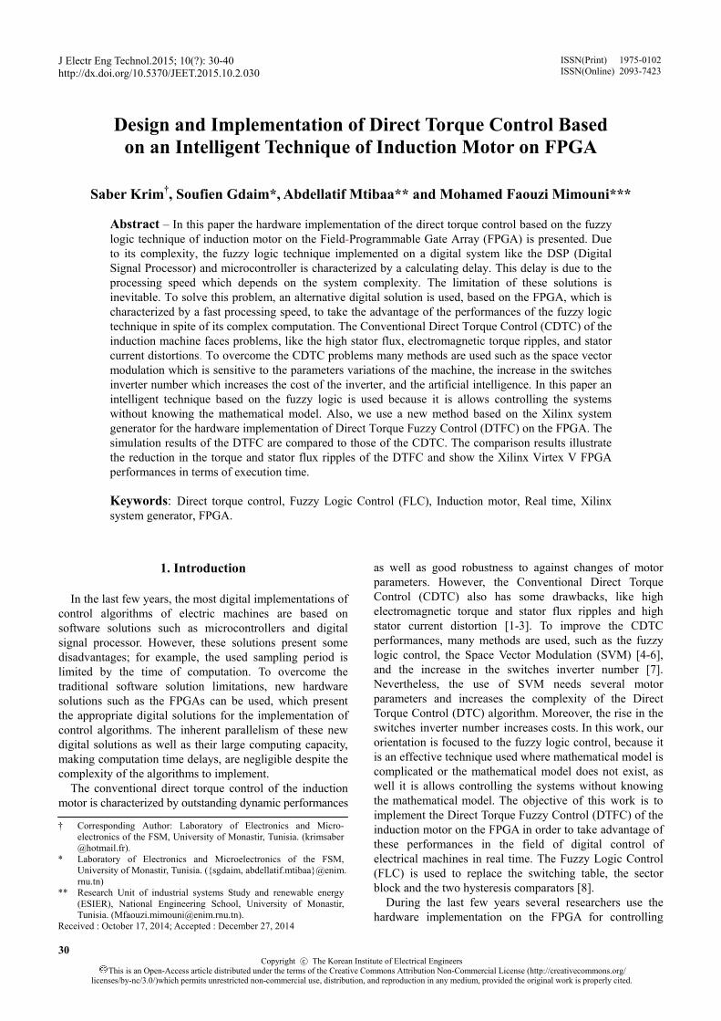
design implemented systems on the FPGA. It has a library of varied blocks, which can be automatically compiled into an FPGA [16]. In this work, the (XSG) is used to implement the DTFC architecture of the induction motor based on Fuzzy Logic Control (FLC) algorithm on an FPGA. In the first step, we begin by implementing the proposed architectures using the XSG blocks available on the Simulink library. Once the Design of the system is completed and gives the desired simulation results, the VHDL code can be generated by the XSG tool [17]. The design flow of the XSG is given in Fig. 1. After generating the VHDL code and the synthesis, we can generate the bitstream file. Then we can move this configuration file to program the FPGA [18].
Fig. 1. Xilinx system generator design flow
3. Basic CDTC Principle of Induction Motor
3.1 Induction machine model
The model of the induction motor expressed in the
stationary “αβ” axes reference frame can be described by [19]:
S r
S S r rS SS
r S
R Rdi L L R
idt L Liα
β ααω ϕ
σ σ
+= − +
1
1
S SS S
S r
S S rS S S
S
rS S
r S S
SS S S
SS S S
vL L
R Rdi L L
i idt L
Rv
L L Ld
R idt
dR i v
dt
v
β α
βα β α
β β
αα α
ββ β
ω ϕσ σ
ωω ϕσ σ
ϕσ σ
ϕ
ϕ
+ +∗
+= − + −
+ +∗
= − +
= − +
(1)
where, iS, φS, VS, R, and L denote the stator currents, stator flux, stator voltage, resistance, and inductance, respectively,
and where ω denotes the rotor speed and 2
1 m
s r
LL L
σ = − is
the redefined leakage inductance. The electromagnetic torque of the induction motor can
be expressed in terms of stator currents and stator flux, which is given by the following expression:
_3 ( )2em est s s s sT p i iα β β αϕ ϕ= − (2)
The mechanical speed equation is given by the following
equation:
3 ( )2
Ls s s s
Td p i i fdt Jα β β αϕ ϕΩ
= − − − Ω (3)
where p is the number of pole pairs, J and TL denote the moment of inertia of the motor and the load torque, Ω is the rotor mechanical speed (pΩ=ω), and f is a viscous friction coefficient.
3.2 CDTC Principle
The basic principle of the CDTC is based on the
application of a voltage particular sequence via a voltage inverter, whose waves are generated through hysteresis comparators in which the flux and torque are trapped to follow their references [20]. The components of the stator voltage vector in the stationary reference frame are calculated as follows:
2 ( )3 21 ( )2
b bs dc a
s dc b c
S Sv v S
v v S S
α
β
⎧ += −⎪⎪
⎨⎪ = −⎪⎩
(4)
where Vdc is the DC bus voltage.
The components of the stator current vector are given by the following expression:
Design and Implementation of Direct Torque Control Based on an Intelligent Technique of Induction Motor on FPGA
32 J Electr Eng Technol.2015;10(1): 30-40
32
1 ( )2
s sa
s sb sc
i i
i i i
α
α
⎧=⎪⎪
⎨⎪ = −⎪⎩
(5)
The module of the stator flux is given by Eq. 6:
2 2s s sα βϕ ϕ ϕ= + (6)
The angle between the stator flux ( , )s s sα βϕ ϕ ϕ and the
reference axis is given by Eq. (7):
( )ss
sarctg β
α
ϕθ
ϕ= (7)
The estimated values of the torque and stator flux are
compared to the reference values Te* and φS*, respectively.
It can be seen from Fig. 3 that the error between the estimated torque Te and the reference torque Te* is the input of a three level hysteresis comparator, where the error between the estimated stator flux magnitude φS and the reference stator flux magnitude φS
* is the input of a two level hysteresis comparator.
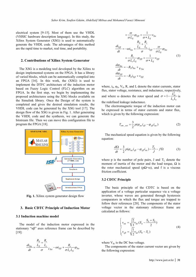
Finally, the outputs of the comparators with a stator flux sector, where the stator flux space vector is located, select an appropriate inverter voltage vector from the switching table (Table 1). The selected voltage vector will be applied to the induction motor at the end of the sample time [21].
Table 1. Switching table for conventional DTC
Eϕ Ec S1 S2 S3 S4 S5 S6 1 V2 V3 V4 V5 V6 V1
1 0 V7 V0 V7 V0 V7 V0 -1 V6 V1 V2 V3 V4 V5 1 V3 V4 V5 V6 V1 V2
0 0 V0 V7 V0 V7 V0 V7 -1 V5 V6 V1 V2 V3 V4
The vectors V1,…,V6 represent the six active vectors that
can be generated by a voltage source inverter where V0 and V7 are the two zero voltage vectors. Fig. 2 gives the partition of the complex plan in six angular sectors Si=1…6.
When the stator flux is in zone i, the vector Vi+1 or Vi-1 is selected to increase the level of the flux, and Vi+2 or Vi-2 is selected to decrease it. At the same time, the vector Vi+1 or Vi-2 is selected to increase the level of the electromagnetic torque, and Vi-1 or Vi-2 is selected to decrease it.
If V0 or V7 is selected, the rotation of the stator flux is stopped and the torque decreases, whereas the amplitude of the stator flux remains unchanged. This shows that the choice of the vector tension depends on the sign of the error of the stator flux and electromagnetic torque independently from their amplitude [21]. This explains why the output of the hysteresis comparator of the stator
flux and torque must be a Boolean variable. We can add a band of hysteresis around zero to avoid useless com-mutations when the error of the stator flux is very small [21].
With this type of hysteresis comparator, we can easily control and maintain the end of the vector flux within a circular ring.
The basic structure of the CDTC induction motor is shown in Fig. 3.
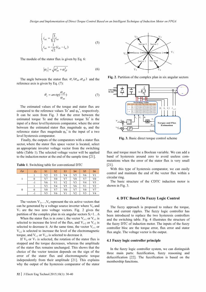
4. DTC Based On Fuzzy Logic Control The fuzzy approach is proposed to reduce the torque,
flux and current ripples. The fuzzy logic controller has been introduced to replace the two hysteresis controllers and the switching table. Fig. 4 illustrates the structure of the fuzzy DTC of induction motor. The inputs of the fuzzy controller bloc are the torque error, flux error and stator flux angle. The voltage vector is the output.
4.1 Fuzzy logic controller principle
In the fuzzy logic controller system, we can distinguish
three main parts: fuzzification, fuzzy reasoning and defuzzification [22]. The fuzzification is based on the membership functions.
Fig. 2. Partition of the complex plan in six angular sectors
Switching Table E ϕ E c S1 S2 S3 S4 S5 S6
1 V2 V3 V4 V5 V6 V1 1 0 V7 V0 V7 V0 V7 V0
-1 V6 V1 V2 V3 V4 V5 1 V3 V4 V5 V6 V1 V2
0 0 V0 V7 V0 V7 V0 V7 -1 V5 V6 V1 V2 V3 V4
refϕ
Tref
( )cba SSS s a bi
Torque and Flux Estimation Sϕ
Tem
NCE E ϕ
230/380v 50 Hz
Sθ +
- +
Fig. 3. Basic direct torque control scheme
Saber Krim, Soufien Gdaim, Abdellatif Mtibaa and Mohamed Faouzi Mimouni
http://www.jeet.or.kr 33
refϕ
Tref
( )cba SSS sabi
Torque and Flux Estimation
Sϕ
Tem
230/380v 50 Hz
Sθ +
-
- PI
re fΩ
Ω
ϕe Te
Fig. 4. Fuzzy direct torque control (DTCF) scheme
4.2 Fuzzy variables
The membership function of the stator flux error is given
by three linguistic terms: Negative (N), Zero (Z) and Positive (P), as shown in Fig. 5(a). The error of the stator flux is given by the following equation:
*
_S ref Sϕ ϕ ϕΔ = − (8) The membership function of the electromagnetic torque
error is given by five linguistic terms: Negative Large (NL), Negative Small (NS), ZEro (ZE), Positive Small (PS) and Positive Large (PL) and shown in Fig. 5(b). The error of the electromagnetic torque is given by the following equation:
*
_em ref emT T TΔ = − (9)
0 a1 a2
1 N P
( )e bϕ ω
NL PL ZE
-1 1
( )Te Nm
0
1 ϕμ Tμ
NS NL
c1 c2
Z
(a) (b) Fig. 5. (a) Fuzzy membership functions of the flux error
( eϕ ); (b) Fuzzy membership functions of the torque error ( Te )
1θ 2θ 5θ 4θ 3θ 6θ 7θ
( )radθ
θμ
1 8θ 11θ 10θ 9θ 12θ
3 5 7 9 11 13 15 17 19 21 2312 12 12 12 12 12 12 12 12 12 12 12π π π π π π π π π π π π
Fig. 6. Stator flux position membership function
1
0 1 2 3 4 5 6
0V 1V4V 3V 2V 5V 6V
Fig. 7. Fuzzy membership functions of output
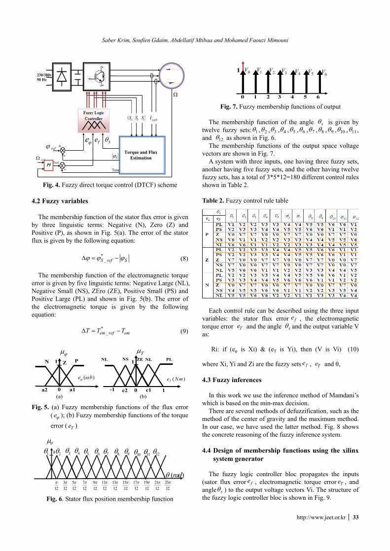
The membership function of the angle sθ is given by
twelve fuzzy sets: 1θ , 2θ , 3θ , 4θ , 5θ , 6θ , 7θ , 8θ , 9θ , 10θ , 11θ , and 12θ as shown in Fig. 6.
The membership functions of the output space voltage vectors are shown in Fig. 7.
A system with three inputs, one having three fuzzy sets, another having five fuzzy sets, and the other having twelve fuzzy sets, has a total of 3*5*12=180 different control rules shown in Table 2.
Table 2. Fuzzy control rule table
Each control rule can be described using the three input
variables: the stator flux error fe , the electromagnetic torque error Te and the angle sθ and the output variable V as:
Ri: if (eφ is Xi) & (eT is Yi), then (V is Vi) (10)
where Xi, Yi and Zi are the fuzzy sets fe , Te and θ,
4.3 Fuzzy inferences
In this work we use the inference method of Mamdani’s
which is based on the min-max decision. There are several methods of defuzzification, such as the
method of the center of gravity and the maximum method. In our case, we have used the latter method. Fig. 8 shows the concrete reasoning of the fuzzy inference system.
4.4 Design of membership functions using the xilinx
system generator The fuzzy logic controller bloc propagates the inputs
(sator flux error fe , electromagnetic torque error Te , and angle sθ ) to the output voltage vectors Vi. The structure of the fuzzy logic controller bloc is shown in Fig. 9.
Design and Implementation of Direct Torque Control Based on an Intelligent Technique of Induction Motor on FPGA
34 J Electr Eng Technol.2015;10(1): 30-40
Inputs
T
S
eeϕ
θ
⎧⎪⎨⎪⎩
Fuzzification (Membership
Fonction)
1 12
( , , )( , , , , )( ,......, )
N Z PNL NS ZE PS PLθ θ
⎧⎪⎨⎪⎩
Rules ( iR )
R1: If ( fe is P) & ( Te is PL) & ( sθ is 1θ ) then (V is V1) R42: If ( fe is N) & ( Te is NL) & ( sθ is 12θ ) then (V is V4)
Defuzzification (Min-Max)
Output Voltage
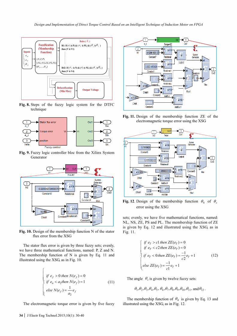
Fig. 8. Steps of the fuzzy logic system for the DTFC
technique
Fig. 9. Fuzzy logic controller bloc from the Xilinx System
Generator
Fig. 10. Design of the membership function N of the stator
flux error from the XSG The stator flux error is given by three fuzzy sets; evenly,
we have three mathematical functions, named: P, Z and N. The membership function of N is given by Eq. 11 and illustrated using the XSG, as in Fig. 10.
2
2
0 ( ) 0( ) 1
1( )
f f
n f
f f
if e then N eif e a then N e
else N e ea
⎧⎪ > =⎪⎪ < =⎨⎪⎪ =⎪⎩
(11)
The electromagnetic torque error is given by five fuzzy
sets; evenly, we have five mathematical functions, named: NL, NS, ZE, PS and PL. The membership function of ZE is given by Eq. 12 and illustrated using the XSG, as in Fig. 11.
1 ( ) 02 ( ) 0
10 ( ) 12
1( ) 11
T T
T T
T T T
T T
if e c then ZE eif e c then ZE e
if e then ZE e ec
else ZE e ec
> =⎧⎪ < =⎪⎪ −
< = +⎨⎪
−⎪ = +⎪⎩
(12)
The angle sθ is given by twelve fuzzy sets:
1 2 3 4 5 6 7 8 9 10 11, , , , , , , , , , ,θ θ θ θ θ θ θ θ θ θ θ and 12θ . The membership function of 4θ is given by Eq. 13 and
illustrated using the XSG, as in Fig. 12.
Fig. 11. Design of the membership function ZE of the electromagnetic torque error using the XSG
Fig. 12. Design of the membership function 4θ of sθerror using the XSG
Saber Krim, Soufien Gdaim, Abdellatif Mtibaa and Mohamed Faouzi Mimouni
http://www.jeet.or.kr 35
4
4
4
4
3 ( ) 0127 ( ) 0125 1( ) 1
31212
1( ) 1712
S S
S S
S S S
S S
if then
if then
if then
else
πθ θ θ
πθ θ θ
πθ θ θ θπ
θ θ θπ
⎧ < =⎪⎪⎪ > =⎪⎪ −
< = +⎨⎪⎪⎪ −
= +⎪⎪⎩
(13)
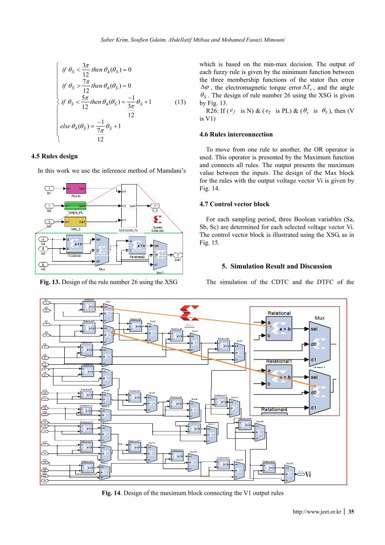
4.5 Rules design
In this work we use the inference method of Mamdani’s
which is based on the min-max decision. The output of each fuzzy rule is given by the minimum function between the three membership functions of the stator flux error ϕΔ , the electromagnetic torque error eTΔ , and the angle Sθ . The design of rule number 26 using the XSG is given
by Fig. 13. R26: If ( fe is N) & ( Te is PL) & ( sθ is 5θ ), then (V
is V1)
4.6 Rules interconnection To move from one rule to another, the OR operator is
used. This operator is presented by the Maximum function and connects all rules. The output presents the maximum value between the inputs. The design of the Max block for the rules with the output voltage vector Vi is given by Fig. 14.
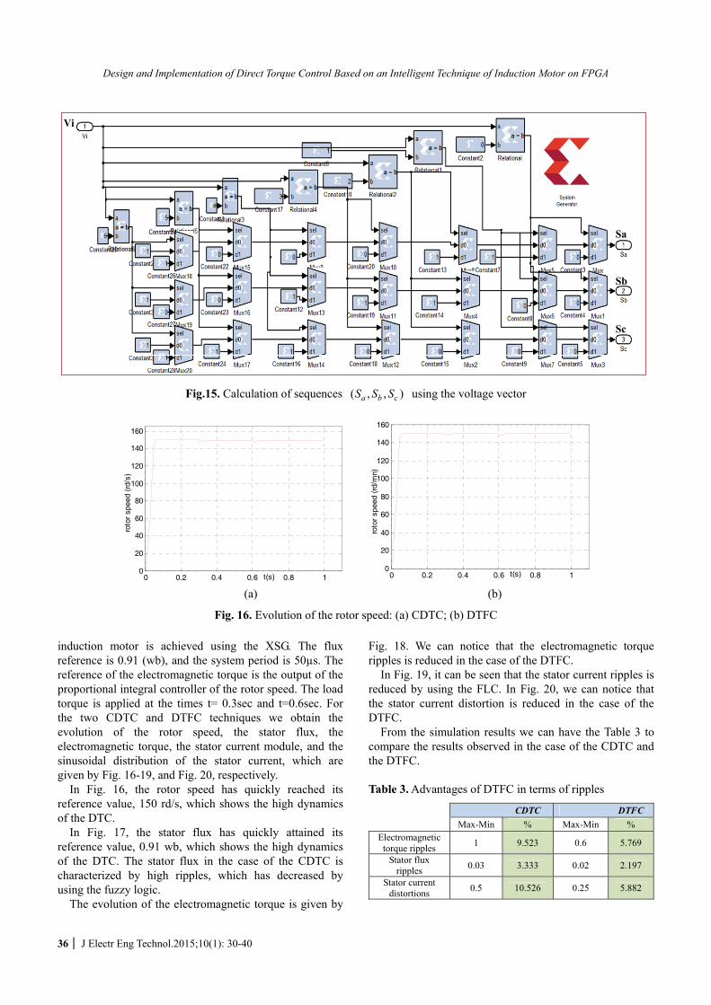
4.7 Control vector block
For each sampling period, three Boolean variables (Sa,
Sb, Sc) are determined for each selected voltage vector Vi. The control vector block is illustrated using the XSG, as in Fig. 15.
5. Simulation Result and Discussion The simulation of the CDTC and the DTFC of the
Vi
Fig. 14. Design of the maximum block connecting the V1 output rules
MINIMUN
Fig. 13. Design of the rule number 26 using the XSG
Design and Implementation of Direct Torque Control Based on an Intelligent Technique of Induction Motor on FPGA
36 J Electr Eng Technol.2015;10(1): 30-40
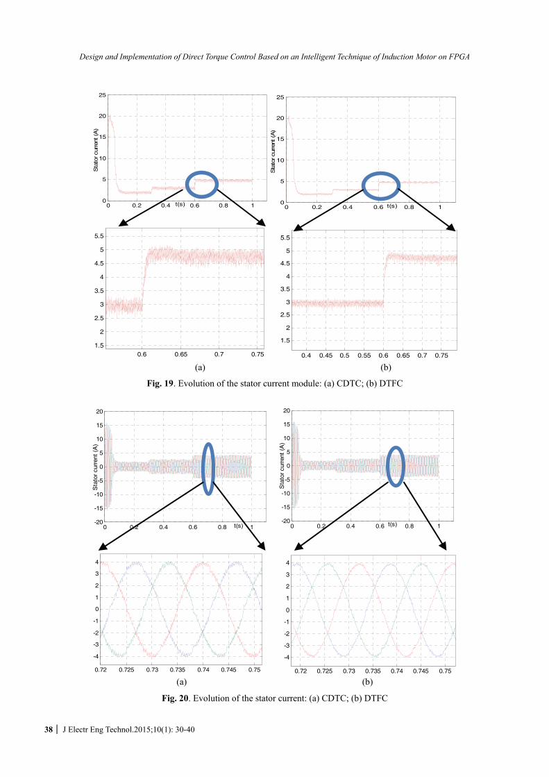
induction motor is achieved using the XSG. The flux reference is 0.91 (wb), and the system period is 50µs. The reference of the electromagnetic torque is the output of the proportional integral controller of the rotor speed. The load torque is applied at the times t= 0.3sec and t=0.6sec. For the two CDTC and DTFC techniques we obtain the evolution of the rotor speed, the stator flux, the electromagnetic torque, the stator current module, and the sinusoidal distribution of the stator current, which are given by Fig. 16-19, and Fig. 20, respectively.
In Fig. 16, the rotor speed has quickly reached its reference value, 150 rd/s, which shows the high dynamics of the DTC.
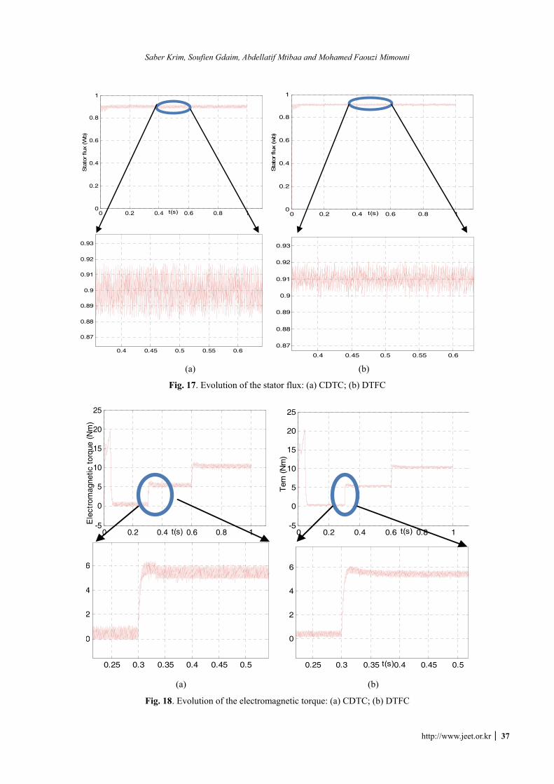
In Fig. 17, the stator flux has quickly attained its reference value, 0.91 wb, which shows the high dynamics of the DTC. The stator flux in the case of the CDTC is characterized by high ripples, which has decreased by using the fuzzy logic.
The evolution of the electromagnetic torque is given by
Fig. 18. We can notice that the electromagnetic torque ripples is reduced in the case of the DTFC.
In Fig. 19, it can be seen that the stator current ripples is reduced by using the FLC. In Fig. 20, we can notice that the stator current distortion is reduced in the case of the DTFC.
From the simulation results we can have the Table 3 to compare the results observed in the case of the CDTC and the DTFC.
Table 3. Advantages of DTFC in terms of ripples
CDTC DTFC Max-Min % Max-Min %
Electromagnetic torque ripples 1 9.523 0.6 5.769
Stator flux ripples 0.03 3.333 0.02 2.197
Stator current distortions 0.5 10.526 0.25 5.882
Sa
Sb
Vi
Sc
Fig.15. Calculation of sequences ( , , )a b cS S S using the voltage vector
0 0.2 0.4 0.6 0.8 10
20
40
60
80
100
120
140
160
t(s)
roto
r sp
eed
(rd/
s)
0 0.2 0.4 0.6 0.8 10
20
40
60
80
100
120
140
160
t(s)
roto
r sp
eed
(rd/
mn)
(a) (b)
Fig. 16. Evolution of the rotor speed: (a) CDTC; (b) DTFC
Saber Krim, Soufien Gdaim, Abdellatif Mtibaa and Mohamed Faouzi Mimouni
http://www.jeet.or.kr 37
0 0.2 0.4 0.6 0.8 10
0.2
0.4
0.6
0.8
1
t(s)
Sta
tor flu
x (W
b)
0 0.2 0.4 0.6 0.8 10
0.2
0.4
0.6
0.8
1
t(s)
Sta
tor flu
x (w
b)
0.4 0.45 0.5 0.55 0.6
0.87
0.88
0.89
0.9
0.91
0.92
0.93
0.4 0.45 0.5 0.55 0.6
0.87
0.88
0.89
0.9
0.91
0.92
0.93
(a) (b)
Fig. 17. Evolution of the stator flux: (a) CDTC; (b) DTFC
0 0.2 0.4 0.6 0.8 1-5
0
5
10
15
20
25
t(s)
Ele
ctro
mag
netic
tor
que
(Nm
)
0 0.2 0.4 0.6 0.8 1-5
0
5
10
15
20
25
t(s)
Tem
(N
m)
0.25 0.3 0.35 0.4 0.45 0.5
0
2
4
6
0.25 0.3 0.35 0.4 0.45 0.5
0
2
4
6
t(s)
(a) (b)
Fig. 18. Evolution of the electromagnetic torque: (a) CDTC; (b) DTFC
Design and Implementation of Direct Torque Control Based on an Intelligent Technique of Induction Motor on FPGA
38 J Electr Eng Technol.2015;10(1): 30-40
0 0.2 0.4 0.6 0.8 10
5
10
15
20
25
t(s)
Sta
tor cu
rren
t (A
)
0 0.2 0.4 0.6 0.8 10
5
10
15
20
25
t(s)
Sta
tor cu
rren
t (A
)
0.6 0.65 0.7 0.751.5
2
2.5
3
3.5
4
4.5
5
5.5
0.4 0.45 0.5 0.55 0.6 0.65 0.7 0.75
1.5
2
2.5
3
3.5
4
4.5
5
5.5
(a) (b)
Fig. 19. Evolution of the stator current module: (a) CDTC; (b) DTFC
0 0.2 0.4 0.6 0.8 1-20
-15
-10
-5
0
5
10
15
20
t(s)
Sta
tor
curr
ent
(A)
0 0.2 0.4 0.6 0.8 1-20
-15
-10
-5
0
5
10
15
20
t(s)
Sta
tor
curr
ent
(A)
0.72 0.725 0.73 0.735 0.74 0.745 0.75
-4
-3
-2
-1
0
1
2
3
4
0.72 0.725 0.73 0.735 0.74 0.745 0.75
-4
-3
-2
-1
0
1
2
3
4
(a) (b)
Fig. 20. Evolution of the stator current: (a) CDTC; (b) DTFC
Saber Krim, Soufien Gdaim, Abdellatif Mtibaa and Mohamed Faouzi Mimouni
http://www.jeet.or.kr 39
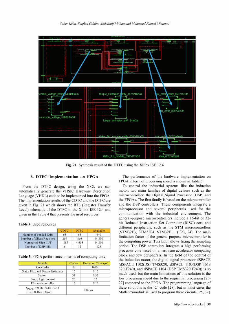
6. DTFC Implementation on FPGA From the DTFC design, using the XSG, we can
automatically generate the VHSIC Hardware Description Language (VHDL) code to be implemented into the FPGA. The implementation results of the CDTC and the DTFC are given in Fig. 21 which shows the RTL (Register Transfer Level) schematic of the DTFC in the Xilinx ISE 12.4 and given in the Table 4 that presents the used resources.
Table 4. Used resources
CDTC DTFC Available Number of bonded IOBs 68 68 640
Number of Slices Registers 259 866 44,800 Number of Slice LUT 1,987 4,655 44,800 Number of DSP48Es 6 12 128
Table 5. FPGA performance in terms of computing time
Module Cycles Execution Time (µs)Concordia 6 0.06
Stator Flux and Torque Estimator 15 0.15 Sector 32 0.32
Fuzzy logic control 20 0.2 PI speed controller 16 0.16
0.06 0.15 0.320.2 0.16 0.89
DTFCtsμ
= + ++ + =
0.89 µs
The performance of the hardware implementation on FPGA in term of processing speed is shown in Table 5.
To control the industrial systems like the induction motor, two main families of digital devices such as the microcontroller, the Digital Signal Processor (DSP) and the FPGAs. The first family is based on the microcontroller and the DSP controllers. These components integrate a microprocessor and several peripherals used for the communication with the industrial environment. The general-purpose microcontrollers include a 16-bit or 32-bit Reduced Instruction Set Computer (RISC) core and different peripherals, such as the STM microcontrollers (STM32F3, STM32F4, STM32F1…) [23, 24]. The main limitation factor of the general purpose microcontroller is the computing power. This limit allows fixing the sampling period. The DSP controllers integrate a high performing processor core based on a hardware accelerator computing block and few peripherals. In the field of the control of the induction motor, the digital signal processor dSPACE (dSPACE 1102(DSP TMS320), dSPACE 1103(DSP TMS 320 F240), and dSPACE 1104 (DSP TMS320 F240)) is so much used, but the main limitations of this solution is the low processing speed due to the sequential processing [25-27] compared to the FPGA. The programming language of these solutions is the ‘C’ code [28], but in most cases the Matlab/Simulink is used to program these circuits [25, 32].
Fig. 21. Synthesis result of the DTFC using the Xilinx ISE 12.4
Design and Implementation of Direct Torque Control Based on an Intelligent Technique of Induction Motor on FPGA
40 J Electr Eng Technol.2015;10(1): 30-40
General-purpose microcontrollers are characterized by their low price [29]. But are not recommended for the complex algorithms due to its low processing speed relative to the FPGA and dSPACE. In Table 4, it is clear that the used resources are negligible relative to the available resources. Therefore, in the industrialization phase we can choose an FPGA with a few resources and a low price. In [30] The FPGA is inexpensive relative to the dSPACE, and it can execute in real time, with a very low execution time, a full complex algorithm, this due to its processing parallelisms. Therefore, the cost of the system based on the FPGA is lower compared to that based on the dSPACE.
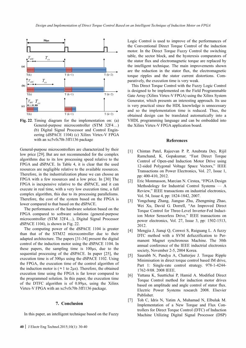
The performances of the hardware solution based on the FPGA compared to software solutions (general-purpose microcontroller (STM 32F4…), Digital Signal Processor dSPACE 1104), is shown in Fig. 22.
The computing power of the dSPACE 1104 is greater than that of the STM32 microcontroller due to their adapted architecture. The papers [31-34] present the digital control of the induction motor using the dSPACE 1104. In these papers, the sampling time is 100µs, due to the sequential processing of the dSPACE. In paper [25], the execution time is of 300µs using the dSPACE 1102. Using the FPGA, the execution time of the control algorithm of the induction motor is ( ≈ 1 to 2µs). Therefore, the obtained execution time using the FPGA is far lower compared to the programmed solution. In this paper, the execution time of the DTFC algorithm is of 0.89µs, using the Xilinx Virtex-V FPGA with an xc5vfx70t-3ff1136 package.
7. Conclusion In this paper, an intelligent technique based on the Fuzzy
Logic Control is used to improve of the performances of the Conventional Direct Torque Control of the induction motor. In the Direct Torque Fuzzy Control the switching table, the sector block, and the hysteresis comparators of the stator flux and electromagnetic torque are replaced by the intelligent technique. The main improvements shown are the reduction in the stator flux, the electromagnetic torque ripples and the stator current distortions. Com-paratively, the execution time is very weak.
This Direct Torque Control with the Fuzzy Logic Control is designed to be implemented on the Field Programmable Gate Array (Xilinx Virtex-V FPGA) using the Xilinx System Generator, which presents an interesting approach. Its use is very practical since the HDL knowledge is unnecessary and so the implementation time is reduced. Thus, the obtained design can be translated automatically into a VHDL programming language and can be embedded into the Xilinx Virtex-V FPGA application board.
References
[1] Chintan Patel, Rajeevan P. P, Anubrata Dey, Rijil Ramchand, K. Gopakumar, “Fast Direct Torque Control of Open-end Induction Motor Drive using 12-sided Polygonal Voltage Space Vectors,” IEEE Transactions on Power Electronics, Vol. 27, Issue 1, pp: 400-410, 2012.
[2] Eric Monmasson, Marcian N. Cirstea, “FPGA Design Methodology for Industrial Control Systems — A Review,” IEEE transactions on industrial electronics, Vol. 54, Issue 4, pp: 1824-1842, 2007.
[3] Yongchang Zhang, Jianguo Zhu, Zhengming Zhao, Wei Xu, David G. Dorrell, “An Improved Direct Torque Control for Three-Level Inverter-Fed Induct-ion Motor Sensorless Drive,” IEEE transactions on power electronics, Vol. 27, Issue 3, pp: 1502-1513, 2012.
[4] Mengjia J, Jianqi Q, Cenwei S, Ruiguang L. A fuzzy DTC method with a SVM defuzzification to Per-manent Magnet synchronous Machine. The 30th annual conference of the IEEE inductrial electronics society, November 2-5, 2004 Korea.
[5] Saurabh N, Pandya A, Chatterjee J. Torque Ripple Minimisation in direct torque control based IM drive, Part 1: Single-rate control strategy. 978-1-4244- 1762-9/08. 2008 IEEE.
[6] Yuttana K, Suuttichai P, Hamid A. Modified Direct Torque Control method for induction motor drives based on amplitude and angle control of stator flux. Electric Power Systems research 2008. Elsevier Publisher.
[7] Toh C, Idris N, Yatim A, Muhamad N, Elbuluk M. Implementation of a New Torque and Flux Con-trollers for Direct Torque Control (DTC) of Induction Machine Utilizing Digital Signal Processor (DSP)
T(k) T (k+1)
T(k)
T (k+2)
T (k+2)
T (k+2)
T(k)
T (k+1)
T (k+1)
ADCT
ADCT
ADCT
exT
exT
exT
(a)
(b)
(c)
50µs
Fig. 22. Timing diagram for the implementation on: (a)General-purpose microcontroller (STM 32F4…)(b) Digital Signal Processor and Control Engin-eering (dSPACE 1104) (c) Xilinx Virtex-V FPGA with an xc5vfx70t-3ff1136 package
Saber Krim, Soufien Gdaim, Abdellatif Mtibaa and Mohamed Faouzi Mimouni
http://www.jeet.or.kr 41
and Field Programmable Gate Arrays (FPGA). Power Electronics Specialists Conference, 2005. IEEE 36th 16-16 June 2005.
[8] K. Rajesh, R. Gupta, S. Bhangale, G. Himanshu, ― Artificial Neural Network Based Direct Torque Control of Induction Motor Drives, IETECH Journal of Electrical Analysis, vol. 2, IETECH Publications, 2008.
[9] H. M. Hasanien. FPGA implementation of adaptative ANN controller for speed regulation of permanent stepper motor drives. Energy Conversion and Management 2011 Elsevier Publisher.
[10] E. Monmasson, L. Idkhajine, M. N. Cirstea, I. Bahri, A. Tisan, M. W. Naouar. FPGAs in Industrial Control Applications. IEEE Transactions on Industrial Infor-matics, vol. 7, issue 2, pp: 224-243. 2011.
[11] M. Dagbagi, L. Idkhajine, E. Monmasson, I. Slama-Belkhodja. FPGA Implementation of Power Elec-tronic Converter Real-Time Model. International Symposium on Power Electronics, Electrical Drives, Automation and Motion. pp: 658-663, 2012.
[12] E. MONMASSON, I.BAHRI, L. IDKHAJINE, A. MAALOUF, M. W. NAOUAR. Recent Advance-ments in FPGA-based controllers for AC Drives Applications. 13th International Conference on Opti-mization of Electrical and Electronic Equipment (OPTIM), IEEE, pp: 8-15, 2012.
[13] M. Shahbazi, P. Poure, S. Saadate, M. R. Zolghadri. FPGA-Based Reconfigurable Control for Fault-Tolerant Back-to-Back Converter without Redun-dancy. IEEE Transactions on Industrial Electronics, vol. 60, issue 8, pp: 3360-3371, 2013.
[14] K. Jezernik, J. Korelic, R. Horvat. PMSM Sliding Mode FPGA-Based Control for Torque Ripple Reduction. IEEE Transactions on Power Electronics, vol. 28, issue 7, pp: 3549-3556, 2013.
[15] T. Sutikno, N. R. Idris, A. Jidin, M. N. Cirstea. An Improved FPGA Implementation of Direct Torque Control for Induction Machines. IEEE Transactions on Industrial Informatics, vol. 9, issue 3, pp: 1272-1279, 2013.
[16] XSG, 1998. Xilinx system generator v2.1 basic tutorial. Printed in USA, http://bwrcs.eecs.berkeley. edu/Classes/cs152/handouts/Tutorials_book.pdf.
[17] J.G. Mailloux; Prototypage Rapide de la Commande Vectorielle sur FPGA à l'Aide des Outils SIMULINK-SYSTEM GENERATOR, l’Université de Québec, Mars 2008 ;
[18] White paper: Using System Generator for Systematic HDL Design, Verification, and Validation WP283 (v1.0) January 17, 2008
[19] S. Belkacem, F. Naceri, R. Abdessemed, “Robust nonlinear control for direct torque control of induct-ion motor drive using space vector modulation”, Journal of Electrical Engineering, Vol. 10, pp. 79-87, 2010.
[20] J. R G Schonfield, «Direct torque control-DTC», ABB Industrial Systems Ltd.
[21] Takahashi I, Noguchi T. A new quick-response and high efficiency control strategy of an induction motor, IEEE trans. Vol IA-22, no 5. 1986.
[22] S. Naaz1, A. Afshar and B. Ranjit, “Effect of dif-ferent defuzzification methods in a fuzzy based load balancing application”, IJCSI International Journal of Computer Science, Vol. 8, Issue (5), pp: 261-267, 2011.
[23] Motor control with STM32®32-bit ARM®-based MCU. Pdf. http://www.st.com/web/en/resource/sales_ and_marketing/promotional_material/brochure/brstm32mc.pdf
[24] STM32 embedded target for MATLAB and Simulink, http://www.st.com/st-web-ui/static/active/en/resource/ technical/document/data_brief/DM00080897.pdf
[25] M. Boussak and K. Jarray, “A High-Performance Sensorless Indirect Stator Flux Orientation Control of Induction Motor Drive”. IEEE Transactions on in-dustrial electronics, Vol. 53, No. 1, pp. 14-49, 2006.
[26] A. Hmidet, R. Dhifaoui and O. Hasnaoui, “Develop-ment, Implementation and Experimentation on a dSPACE DS1104 of a Direct Voltage Control Scheme”, Journal of Power Electronics, Vol. 10, N°.5, pp. 468-476, 2010.
[27] A. Abbou, T. Nasser, H. Mahmoudi, M. Akherraz1, A. Essadki, “dSPACE IFOC Fuzzy Logic Controller Implementation for Induction Motor Drive”. Journal of Electrical Systems, vol. 8, No. 3, pp. 317-327, 2012.
[28] dSpace DS1102 / DS1104 : C programs for induction motor vector control. http://www.baghli.com/dspace. php#Download
[29] P.M. Menghal, A. Jaya Laxmi, “Real Time Control of Electrical Machine and Drives: A Review”. Interna-tional journal of advances in electrical engineering and technology. Vol. 1, Issue 4, pp. 112-126. 2011.
[30] Low Cost FPGA Based Replacement for dSPACE Units in the Electric Drives Laboratory, http://cusp. umn.edu/Napa_2013/Friday/Tom_P_Napa.pdf.
[31] Bhoopendra Singh, Shailendra Jain, and Sanjeet Dwivedi, “Direct Torque Control Induction Motor Drive with Improved Flux Response”. Hindawi Publishing Corporation Advances in Power Elec-tronics, Vol. 2012, Article ID 764038, pp.1-11.
[32] A. ELBACHA, Z. BOULGHASOUL and E. ELWARRAKI, A Comparative Study of Rotor Time Constant Online Identification of an Induction Motor Using High Gain Observer and Fuzzy Compensator”, WSEAS TRANSACTIONS on SYSTEMS and CONTROL, Vol 7, No.°2, pp.37-53, 2012.
[33] Vojkan Kostić, Milutin Petronijević, Nebojša Mitrović, Bojan Banković, “Experimental verification of direct torque control methods for electric drive application”, Automatic Control and Robotics Vol. 8, No 1, pp. 111-126, 2009.
Design and Implementation of Direct Torque Control Based on an Intelligent Technique of Induction Motor on FPGA
42 J Electr Eng Technol.2015;10(1): 30-40
[34] Bhoopendra singh, Shailendra Jain, Sanjeet Dwivedi, “Experimental Direct Torque Control Induction Motor Drive with Modified Flux Estimation and Speed control Algorithm”, IOSR Journal of Engineering, Vol. 2, No.6 pp. 1296-1300, 2012.
Saber KRIM received the degree in Electrical Engineering from National School of Engineering of Monastir, Tunisia in 2011. In 2013 he received his M.S degree in electrical Engineer-ing from Monastir University, Tunisia. He is currently pursuing the Ph.D. degree with University of Monastir,
Tunisia. His current research interests include rapid prototyping and reconfigurable architecture for real-time control applications of electrical system.
Soufien GDAIM received the degree in Electrical Engineering from Na-tional School of Engineering of Sfax, Tunisia in 1998. In 2007 he received his M.S degree in electronic and real-time informatic from Sousse University and received his PhD degree in Electrical Engineering in 2013 from
ENIM, Tunisia. His current research interests include rapid prototyping and recon-figurable architecture for real-time control applications of electrical system.
Abdellatif MTIBAA is currently Professor in Micro-Electronics and Hardware Design with Electrical De-partment at the National School of Engineering of Monastir and Head of Circuits Systems Reconfigurable ENIM-Group at Electronic and microelec-tronic Laboratory. He holds a Diploma
in Electrical Engineering in 1985 and received his Ph.D degree in Electrical Engineering in 2000. His current research interests include System on Programmable Chip, high level synthesis, rapid prototyping and reconfigurable architecture for real-time multimedia applications. Dr. Abdellatif Mtibaa has authored/coauthored over 100 papers in international journals and conferences. He served on the technical program committees for several international conferences. He also served as a co-organizer of several international conferences.
Mohamed Faouzi Mimouni received his Mastery of Science and DEA from ENSET, Tunisia in 1984 and 1986, respectively. In 1997, he obtained his Doctorate Degree in Electrical Engin-eering from ENSET, Tunisia. He is currently Full Professor of Electrical Engineering with Electrical Depart-
ment at the National School of Engineering of Monastir. His specific research interests are in the area Power Electronics, Motor Drives, Solar and Wind Power generation. Dr. Med Faouzi MIMOUNI has authored/coauthored over 100 papers in international journals and conferences. He served on the technical program committees for several international conferences.
Top Related