


γλώσσες
Σελίδες
Νομικός


COLOUR TV FUNDAMENTALS
Chromaticity diagram
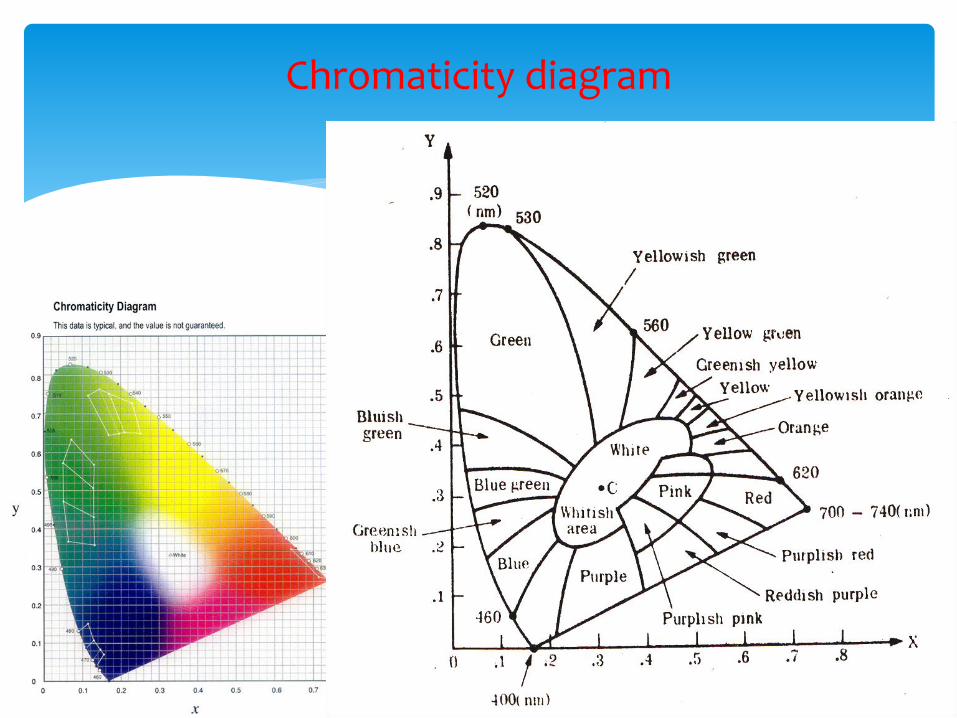
Colour camera
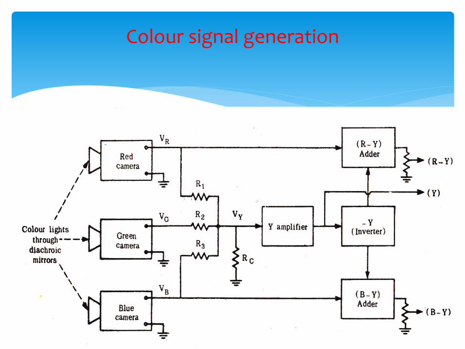
Colour signal generation
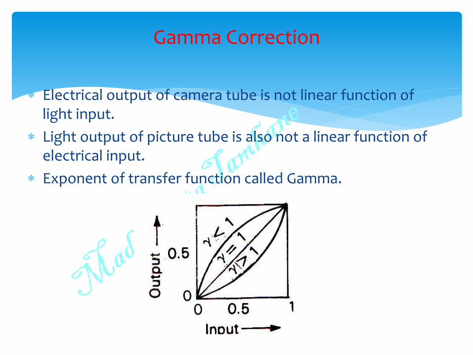
Electrical output of camera tube is not linear function of light input.
Light output of picture tube is also not a linear function of electrical input.
Exponent of transfer function called Gamma.
Gamma Correction
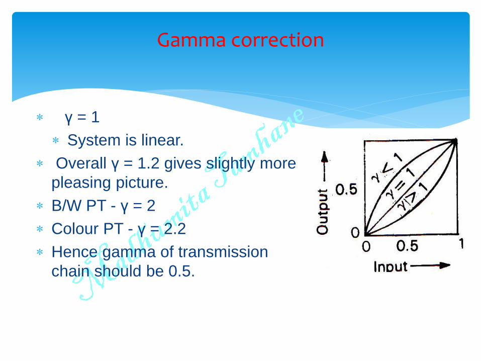
γ = 1
System is linear.
Overall γ = 1.2 gives slightly more
pleasing picture.
B/W PT - γ = 2
Colour PT - γ = 2.2
Hence gamma of transmission
chain should be 0.5.
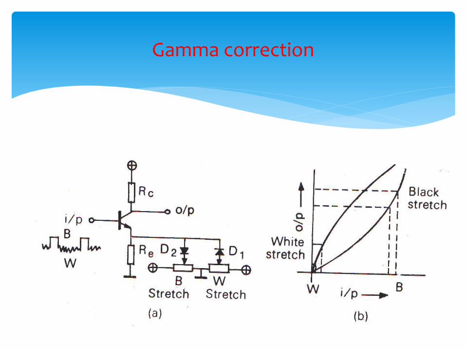
Gamma correction
Gamma correction
Colour Picture Tube
Delta Gun Colour Picture Tube
Gun-in-Line or Precision-in-line Colour Picture Tube
Single gun or Trintron Colour Picture Tube
Colour Picture Tube
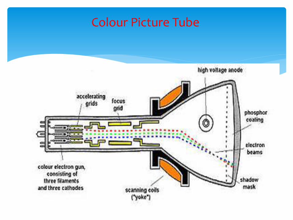
Radio Corporation of America RCA
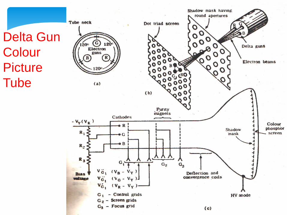
3 separate guns for 3 colours.
Guns equally spaced at 120 ,tilted towards axis.
Screen coated with 3 different phosphors for R, G, B.
Triad contains 1 dot of each colour.
3,33,000 triads.
Eye integrates 3 colour information to give a sensation of combined hue.
Shadow mask.
One hole per triad.
All stray electrons (80%) get collected by mask.
Hence need higher EHT.
Delta Gun Colour Picture Tube
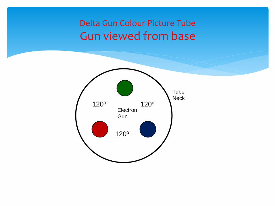
Delta Gun Colour Picture Tube
Gun viewed from base
120º 120º
120º
Electron
Gun
Tube
Neck
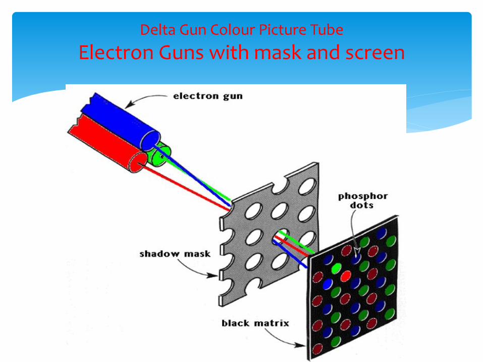
Delta Gun Colour Picture Tube
Electron Guns with mask and screen
Delta Gun
Colour
Picture
Tube
Convergence is difficult.
Very elaborate arrangements to overcome it.
Focus not sharp over entire screen.
As focus and convergence planes for three guns separated by 120º are not same.
Mask passes only 20% of electrons.
Delta Gun Colour Picture Tube
Disadvantages
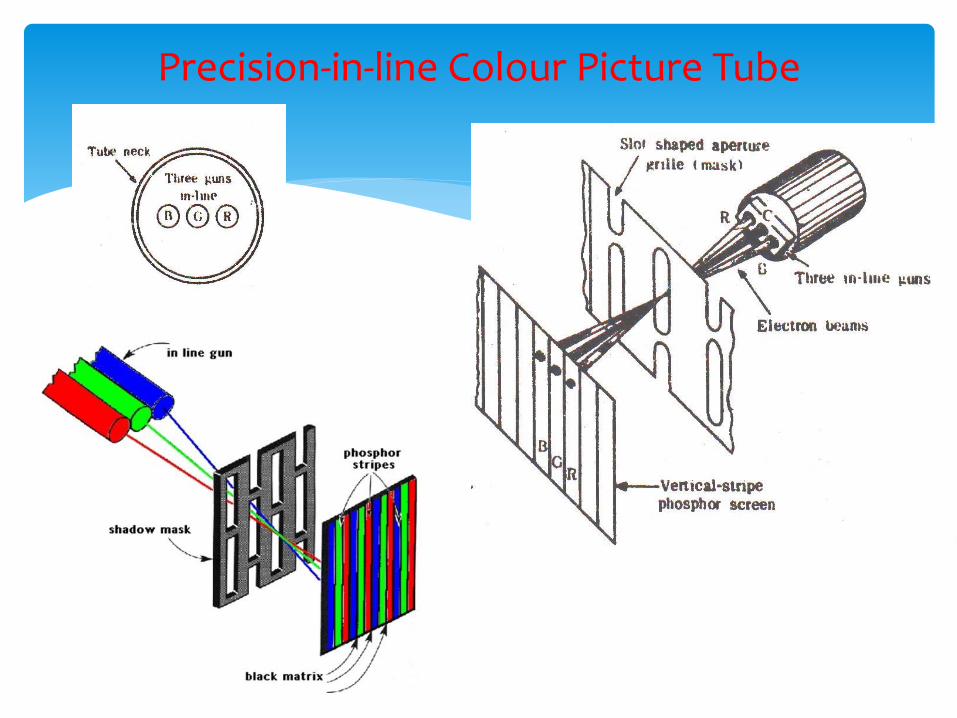
Precision-in-line Colour Picture Tube
3 Guns in line simplifies convergence adjustment.
Colour phosphors in form of vertical stripes.
Distance same as in Delta gun.
More efficient.
Larger % of electrons pass through mask.
Fewer convergence adjustments.
Most widely used.
Precision-in-line Colour Picture Tube
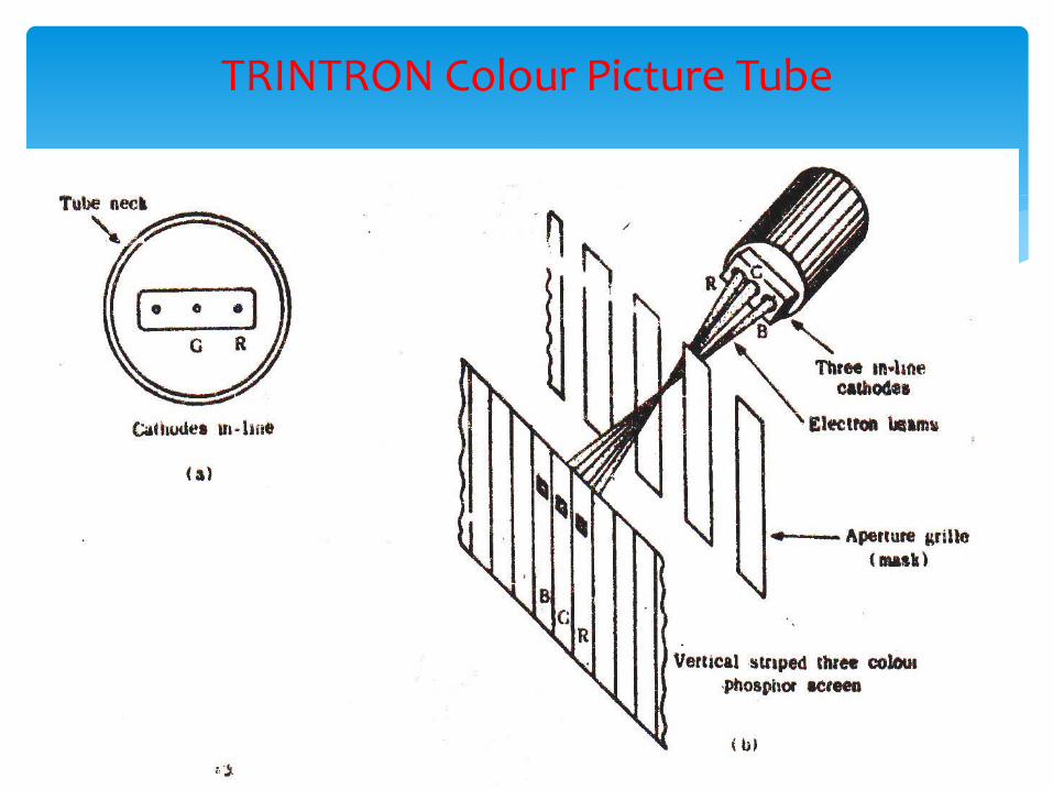
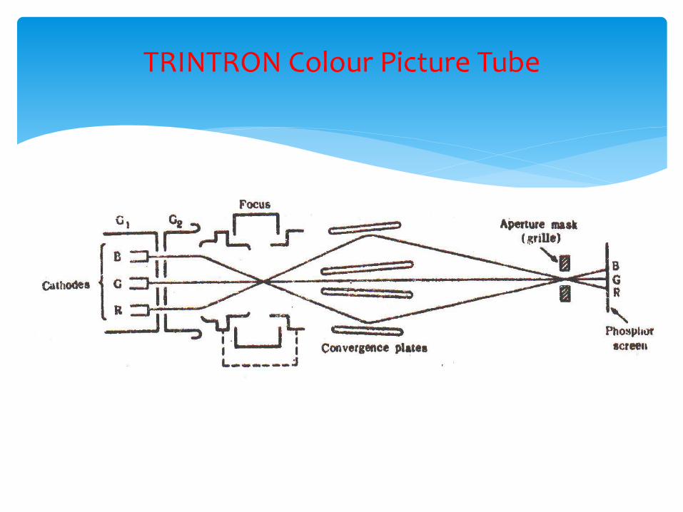
By Sony Corporation, Japan
Single gun having three cathodes.
Simplified construction as only one electron assembly.
Three phosphor triads arranged in vertical strips.
Each strip is few thousandth of a cm.
A metal aperture grill has one slot each triad.
Grill has greater electron transparency.
Three beams appear to emerge from same point.
TRINTRON Colour Picture Tube
TRINTRON Colour Picture Tube
TRINTRON Colour Picture Tube
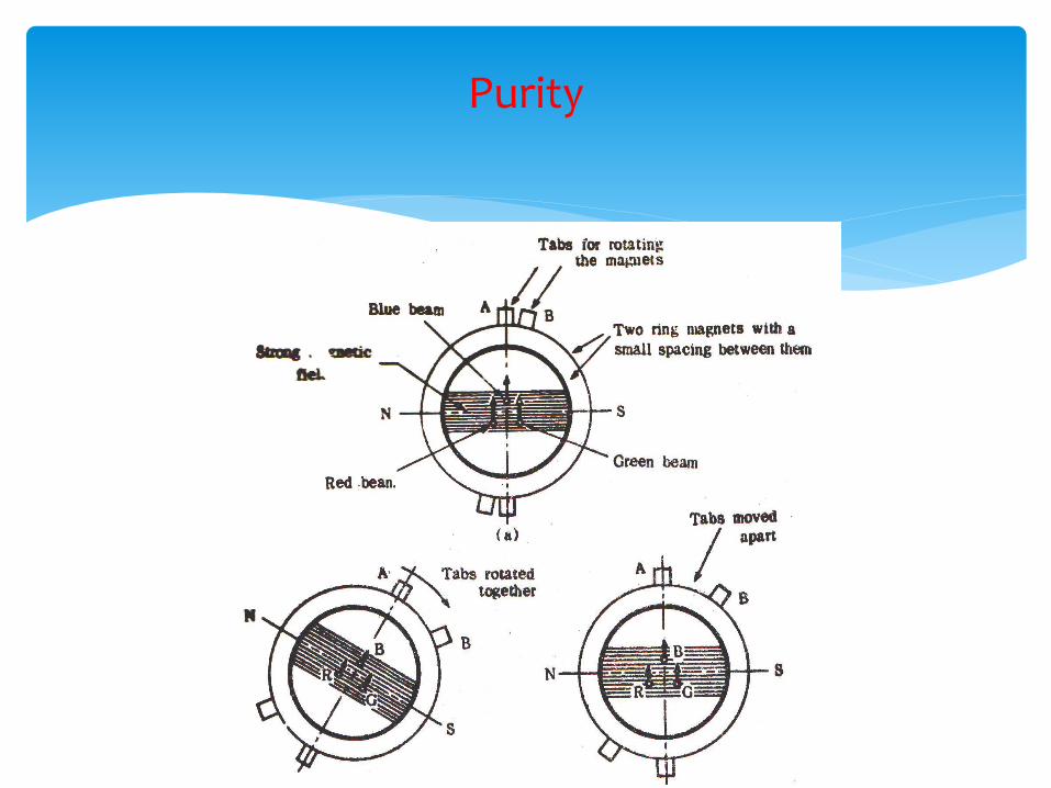
Each beam must fall at center of corresponding dot.
Irrespective of position of triad on screen.
Circular magnets called purity magnets on neck of yoke does the alignment.
If all tabs moved together, they change direction of field.
If tabs are separated, magnetic field reduces.
Purity and Convergence
Purity
2, 4, 6 pole magnets to achieve collective or individual beam deflection.
Error may also occur if yoke is not positioned properly.
Purity
Technique that all electrons hit the same part of the screen to produce 3 coincidental rasters.
Errors–
Non-coincidental convergence plane.
Non-uniformity of deflection field.
Flat surface of picture tube screen.
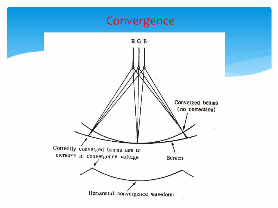
Convergence
Convergence
Correction:
Static and dynamic convergence.
Static convergence by permanent magnet.
Once correctly set, brings the beam into convergence in the central area of the screen
Dynamic convergence converges beam over rest of the screen.
Dynamic convergence achieved by additional winding in series with yoke coil.
Achieved by continuously varying magnetic field.
Instantaneous strength depends upon position of the spot on the screen.
Convergence
• Static pincushion may cause purity problem.
• Dynamic pincushion correction.
• This stretches the horizontal width and vertical size of raster at edges.
Pincushion correction
• Due to Earth magnetic field and other nearby magnetic fields, mask and mounting frame may get magnetized.
• Will cause purity error causing in colour patches.
• Can be repaired by influencing the screen by an alternating magnetic field which gradually reduces to zero.
Degaussing
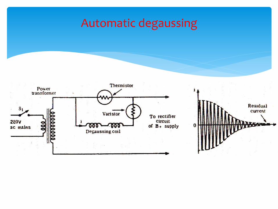
Automatic degaussing
• At switch ON, thermistor is cold and has high resistance.
• More AC passes through coil and varistor, causing alternating magnetic field.
• Thermistor gradually heats up, reducing its resistance.
• More current flows through thermistor.
Lesser current through coil and varistor.
Heats thermistor further
• This continues till
current through thermistor becomes maximum.
Current through varistor and coil gradually reduces to zero.
• Components chosen to give initial surge of 4ampere to D.Coil.
• Final current less than 25mA in less than a second.
Automatic degaussing
• R G B must combine to give to give white.
• 3 phosphors have different efficiencies.
• 3 guns may not have identical emission and cutoff point (Ip/Vgk).
• Tint appears instead of pure grey shades for monochrome transmission.
• Suitable adjustment required to produce correct monochrome information with no colour tint for all settings of contrast control.
Grey Scale Tracking
• Appearance of tint instead of pure grey shades in areas of low brightness.
• Necessary to bring cutoff points in coincidence.
• Achieved by making screen grid voltage (1st anode) different for each cathode.
• Potentiometers are normally provided in DC voltage supply to 3 screen grids.
Grey Scale Tracking Adjustment on low light
• All levels of light must be correctly reproduced.
• Need to Compensate for slightly different slopes and also for substantially different phosphor efficiencies.
• Achieved by the video signal Y drive to the 3 guns.
• Red has lower efficiency, maximum video signal Y fed to red cathode.
• By potentiometer B and G inputs are varied to produce optimum reproduction of high lights.
Grey Scale Tracking Adjustment on high light
3 Systems---
American NTSC(National Television System Committee)
German PAL( Phase Alteration by Line)
French SECAM(Sequential couleures a memoire)
All systems are good.
India adopted PAL for 625 line CCIR-B standard for B/W.
NTSC and PAL being similar are dealt together.
Colour signal transmission and reception
Should accommodate hue and saturation in same band of 7MHz.
Colour signal should not disturb B/W information and vice versa.
Done by Frequency interleaving.
Colour signal transmission

Should accommodate hue and saturation in same band of 7MHz.
Colour signal should not disturb B/W information and vice versa.
Done by Frequency interleaving.
Colour signal transmission
Video signal band bears a definite relation with scanning frequencies.
Energy content of video signal is contained in individual energy “bundles”.
Bundles occur at harmonics of line frequency.15625Hz
Components of each bundle separated by multiple of field frequency. 50, 100, 150…
Each bundle has peak at exact line harmonic gradually reducing in amplitude on either side.
Amplitudes of bundles reduce towards higher harmonics of line frequency.
Frequency interleaving
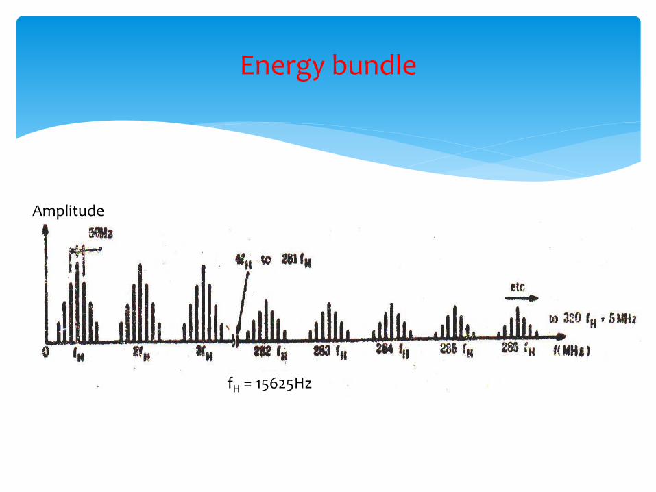
Energy bundle
Amplitude
fH = 15625Hz
Vertical sidebands contain lesser energy than Horizontal because of lower rate of scanning frequencies.
Overall Energy contents decreases to very small value beyond 3.5MHz from picture carrier.
Part of B/W BW unused at spacing between the bundles.
Used for colour energy bundles.
Energy bundle
Colour subcarrier so chosen that side band energy frequencies exactly fall between harmonics of line frequencies.
Hence colour subcarrier chosen to be odd multiple of half of line frequency.
To avoid any cross talk between B/W and colour info, higher portion of B/W BW is chosen to place coloue BW.
Hence Colour subcarrier is 567 times half line frequency.
PAL = 567x 15625/2 = 4.43MHz
NTSC = 455x 15750/2 = 3.58MHz
Colour Energy bundle
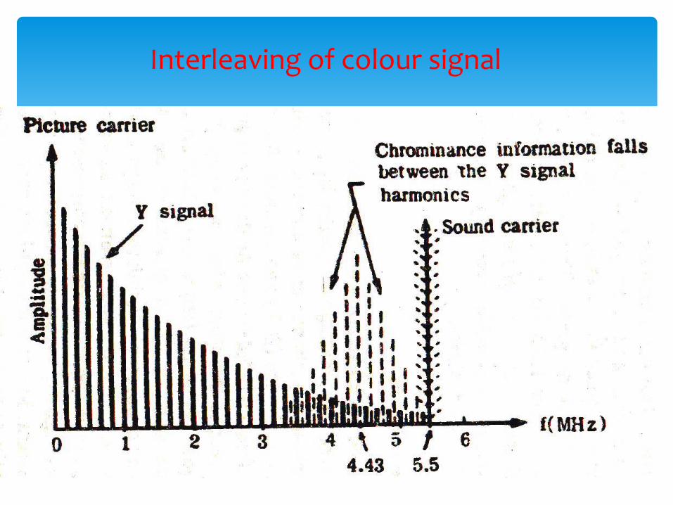
Interleaving of colour signal
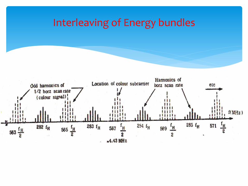
Interleaving of Energy bundles
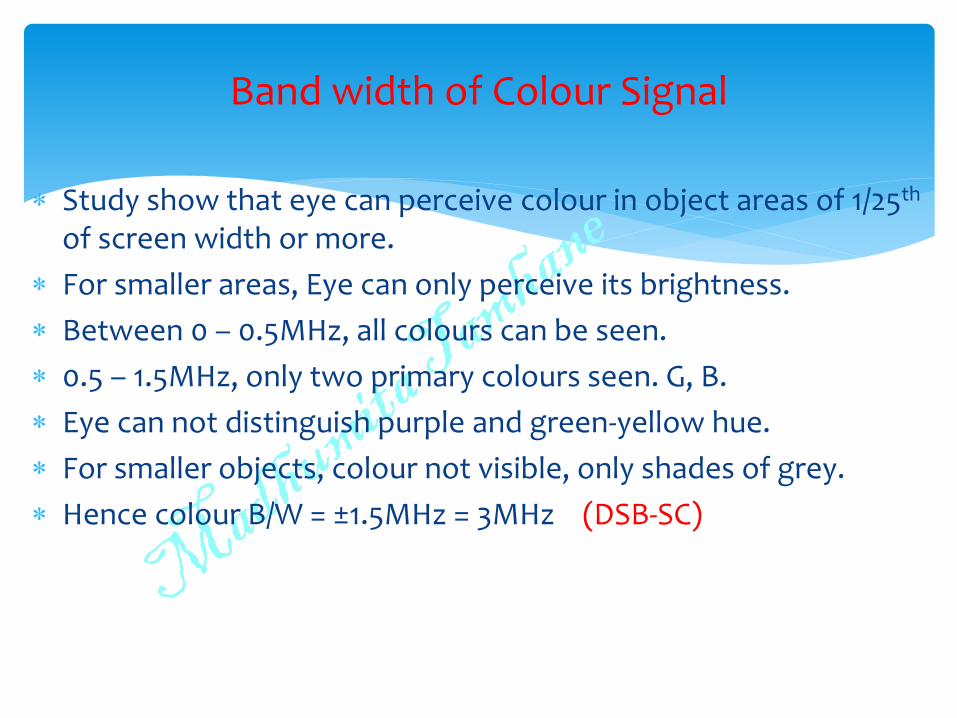
Study show that eye can perceive colour in object areas of 1/25th of screen width or more.
For smaller areas, Eye can only perceive its brightness.
Between 0 – 0.5MHz, all colours can be seen.
0.5 – 1.5MHz, only two primary colours seen. G, B.
Eye can not distinguish purple and green-yellow hue.
For smaller objects, colour not visible, only shades of grey.
Hence colour B/W = ±1.5MHz = 3MHz (DSB-SC)
Band width of Colour Signal
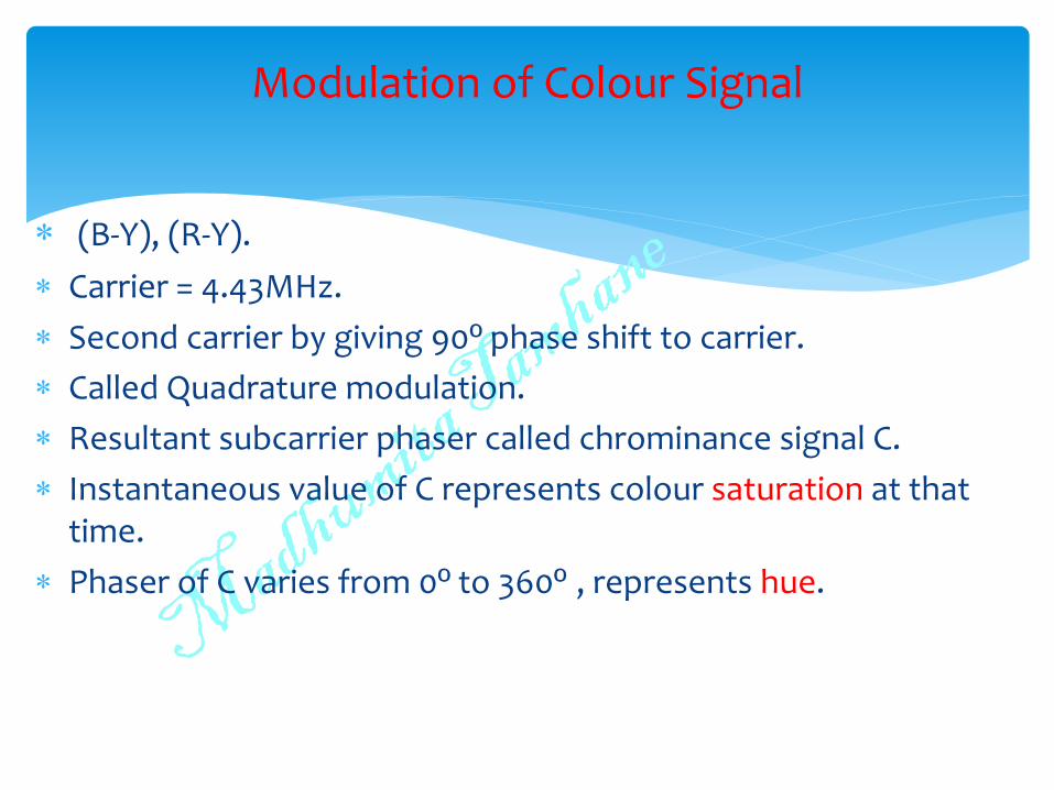
(B-Y), (R-Y).
Carrier = 4.43MHz.
Second carrier by giving 90º phase shift to carrier.
Called Quadrature modulation.
Resultant subcarrier phaser called chrominance signal C.
Instantaneous value of C represents colour saturation at that time.
Phaser of C varies from 0º to 360º , represents hue.
Modulation of Colour Signal
(R-Y) = R - 0.59G – 0.3R – 0.11B
= 0.7R – 0.59G – 0.11B
(B-Y) = B - 0.59G – 0.3R – 0.11B = 0.89B – 0.59G – 0.3R
Modulation of COLOUR Signal
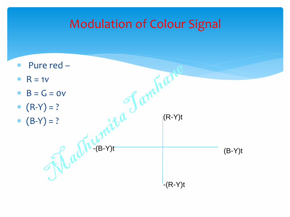
Pure red –
R = 1v
B = G = 0v
(R-Y) = ?
(B-Y) = ?
Modulation of Colour Signal
(B-Y)t
-(R-Y)t
(R-Y)t
-(B-Y)t
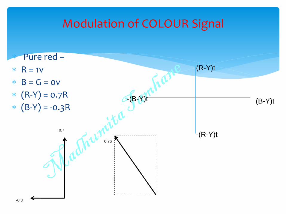
Pure red –
R = 1v
B = G = 0v
(R-Y) = 0.7R
(B-Y) = -0.3R
Modulation of COLOUR Signal
0.7
-0.3
0.76
(B-Y)t
-(R-Y)t
(R-Y)t
-(B-Y)t
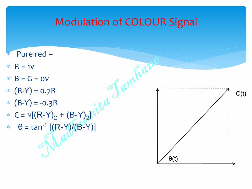
Pure red –
R = 1v
B = G = 0v
(R-Y) = 0.7R
(B-Y) = -0.3R
C = √[(R-Y)2 + (B-Y)2]
θ = tan-1 [(R-Y)/(B-Y)]
Modulation of COLOUR Signal
C(t)
θ(t)
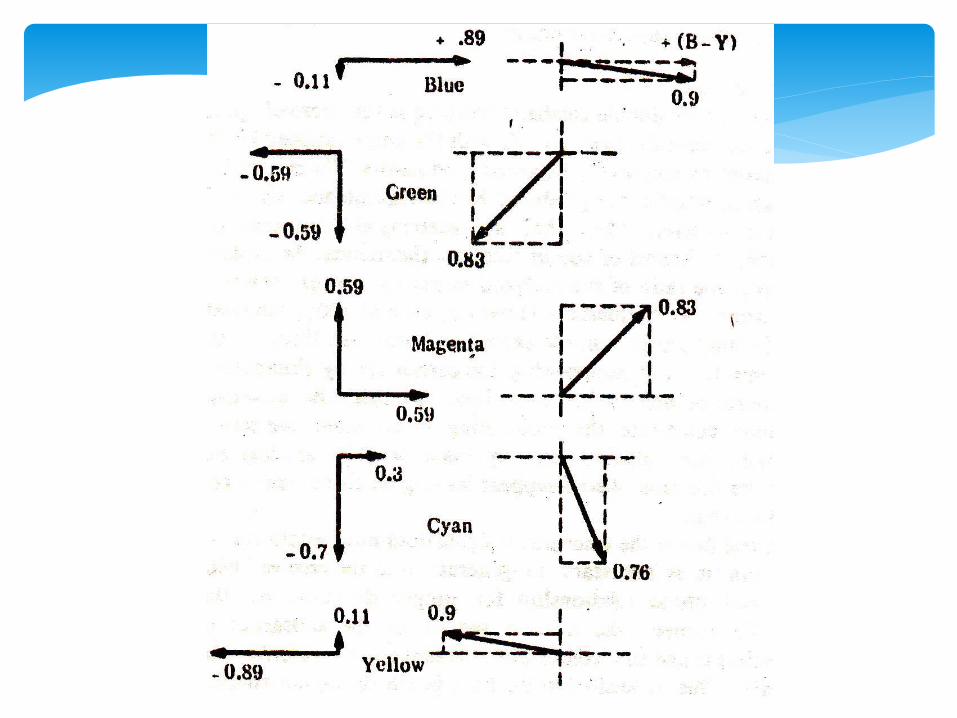
Similarly can be found for pure Blue, Green, Magenta, Cyan, Yellow
Modulation of Colour Signal
(R-Y) and (B-Y) modulate colour subcarrier using DSB-SC.
Avoids interference due to colour subcarrier.
Avoids power wastage.
In B/W transmission, (R-Y), (B-Y) are zero. No colour carrier. Hence no chrominance signal.
But we need to generate Colour subcarrier at receiver for detection of DSB-SC.
It should have same frequency and phase.
Hence 8-11 cycles of subcarrier sent as pilot for synchronization.
Rides the back porch of Blanking pulse.
Colour burst signal
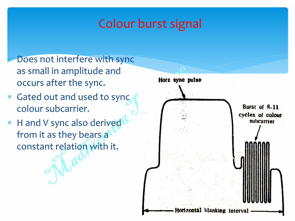
Does not interfere with sync as small in amplitude and occurs after the sync.
Gated out and used to sync colour subcarrier.
H and V sync also derived from it as they bears a constant relation with it.
Colour burst signal
(R-Y) and (B-Y) modulate 4.43MHz colour subcarrier and 4.43MHZ with 90º phase shift.
Gives C, θ(t)
C when added to Y, rides over Y.
Chrominance Signal Weighing Factor
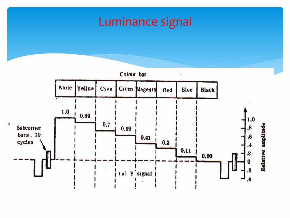
Luminance signal

Chrominance signal generation
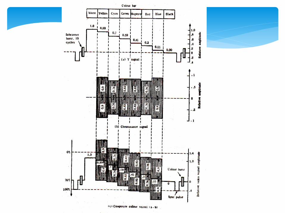
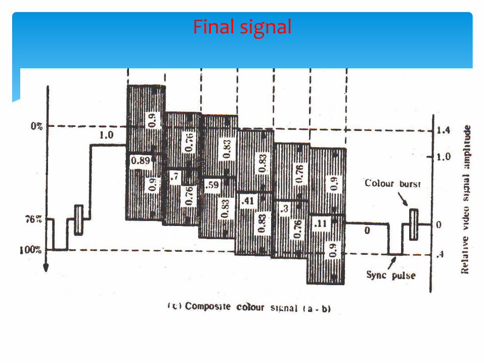
Final signal
Over-modulation must be avoided.
Over modulation reduced by reducing (R-Y) and B-Y) before modulating colour carrier.
(R-Y) and B-Y) scaled down.
(R-Y)’ = 0.877(R-Y)
(B-Y)’ = 0.493(B-Y)
And then modulate the carrier.
Weighing Factor
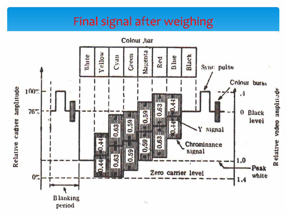
Final signal after weighing
New values still over modulates.
In real life, such pure colours never occurs.
Hence amplitude levels never reach shown peak values.
No over modulation in real signals.
At receiver, (R-Y) and (B-Y) need to be scaled up to bring them to original value.
Needs controlled amplification.
Due to weighing, there is change in amplitude and phase of various colours.
Weighing Factor
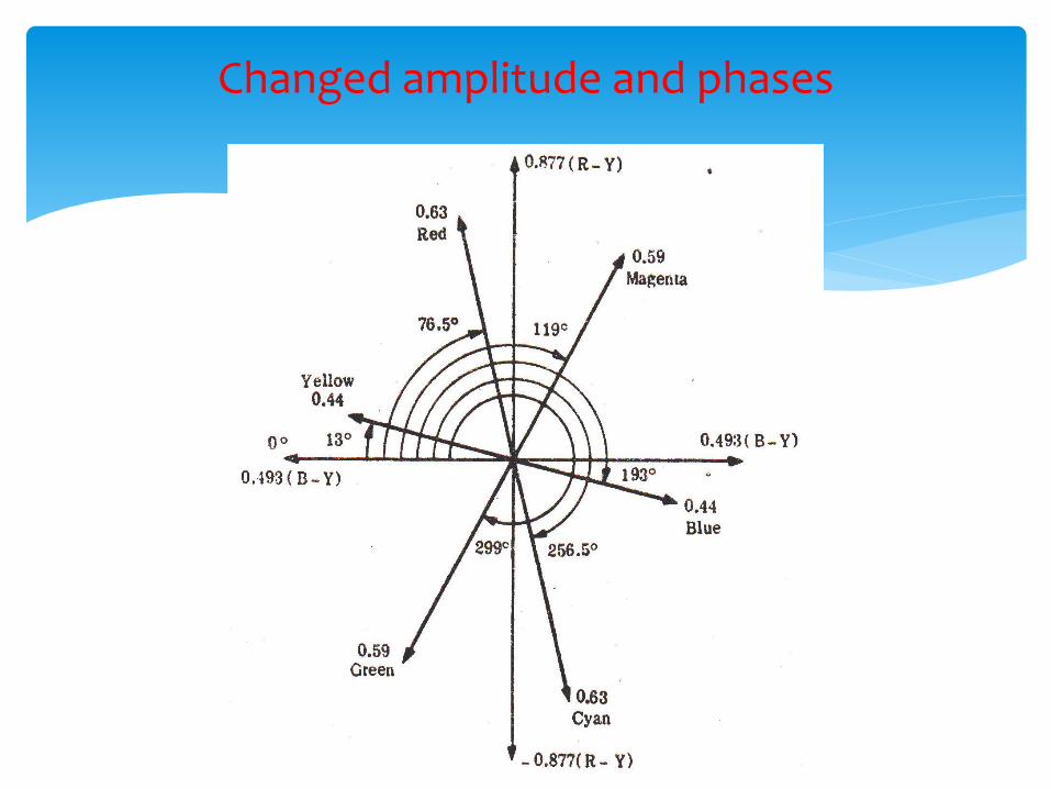
Changed amplitude and phases
Colour B/W reduced to 2MHz.
Eye’s resolution of colours along reddish blue – yellowish green axis on colour circle is much less than colours which lie around yellowish red – greenish blue axis.
Two new signals Q and I chosen to represent these areas.
NTSC SYSTEM
I and Q subcarrier
+
+
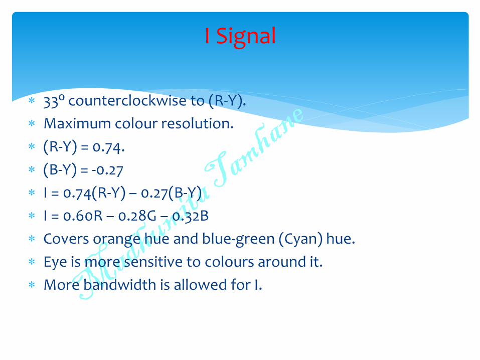
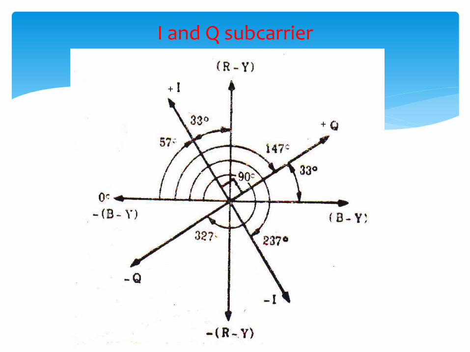
33º counterclockwise to (R-Y).
Maximum colour resolution.
(R-Y) = 0.74.
(B-Y) = -0.27
I = 0.74(R-Y) – 0.27(B-Y)
I = 0.60R – 0.28G – 0.32B
Covers orange hue and blue-green (Cyan) hue.
Eye is more sensitive to colours around it.
More bandwidth is allowed for I.
I Signal
33º counterclockwise to (B-Y).
(R-Y) = 0.48.
(B-Y) = 0.41
Q = ?
Q Signal
33º counterclockwise to (B-Y).
(R-Y) = 0.48.
(B-Y) = 0.41
Q = 0.21R - 0.52G + 0.31B
Covers reddish blue (Magenta) and yellow-green hue.
Eye is less sensitive to colours around it.
Less bandwidth is allowed for Q.
Q Signal
0 to 0.5MHz – Both I and Q are active.
0.5 to 1.5MHz – Q drops out. Only I remains.
DSC-SC allowed for Q.
BW = 1MHZ
VSC allowed for I.
Upper side band = 0.5MHz
Lower side band = 1.5MHz
BW = 2MHZ
Total BW = 2MHz for colour, 6MHz for NTSC system.
Bandwidth of I and Q Signal
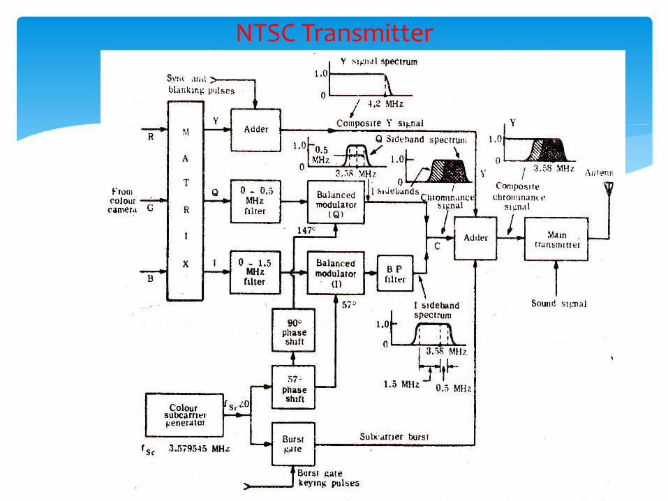
NTSC Transmitter
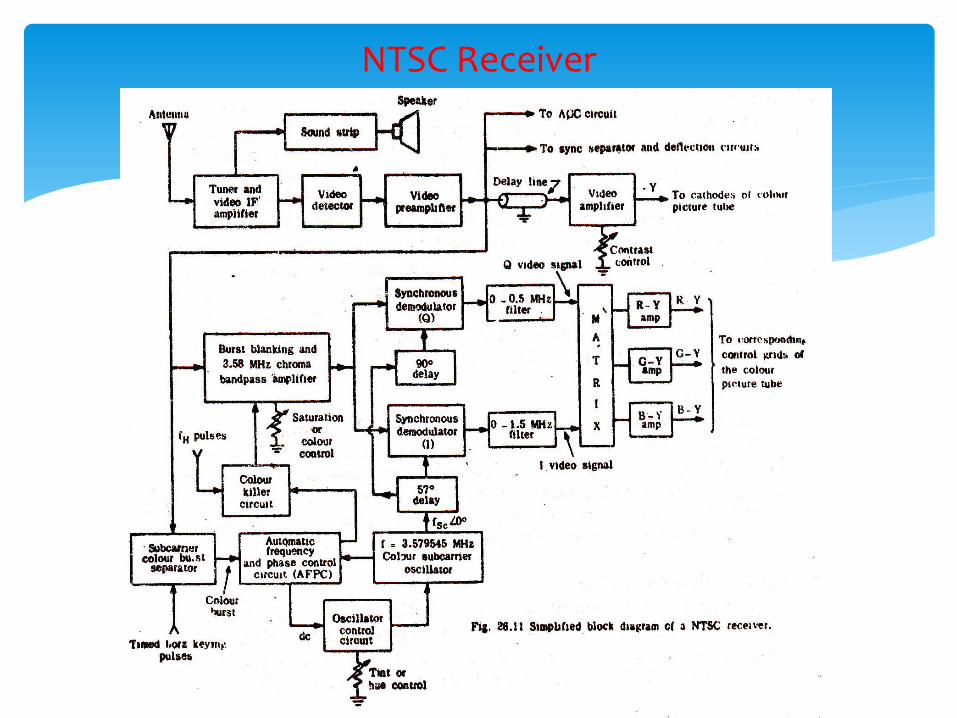
NTSC Receiver
500ns delay to y signal.
Chrominance signal during active trace time.
Burst signal during retrace time.
Colour killer ckt kills video amplifier during retrace to prevent burst affecting the picture.
Done by application of blanking pulses to turn the bias of amplifier off.
Final colour amplifiers to compensate for weighing factor.
R-Y boosted by 1.4
G-Y boosted by 2.03
B-Y attenuated by 0.7
NTSC Receiver
Sensitive to transmission path difference which introduces phase errors that result in colour changes in picture.
Phase changes can also take place when changeover between local and TV network system take place.
Chroma phase angle is also affected by the level of the signal while passing through various circuits.
Cross talk between demodulator outputs at the receiver can cause distortions.
All above require automatic tint control with provision of manual control.
Limitations of NTSC Receiver
At Telefunken laboratory in the Federal Republic of Germany.
Phase error susceptibility of NTSC system has been largely eliminated.
PAL Colour system
Weighted (R-Y) and (B-Y) are used.
(R-Y) and (B-Y) both are given same B/W of 1.3 MHz.
Gives better colour reproduction.
Vestigial Sideband modulation used.
USB – attenuation slope starts at 0.57MHz.
(5-4.43 = 0.57MHz)
LSB – Extends to 1.3MHz before attenuation begins.
Colour subcarrier = 4.43361875MHz.
Gives better cancellation of dot pattern interference.
Features of PAL Colour system
(R-Y) and (B-Y) modulated with subcarrier using QAM as in NTSC but with a difference.
Phase of one carrier is 0º.
Phase of other carrier shifts between +90 º to -90 º at alternate lines .
Hence the name Phase Alteration by Line(PAL).
This cancels hue errors resulting from unequal phase shifts in the transmitted signal.
Shifting of phase occurs during line blanking interval to avoid visible disturbance.
Features of PAL Colour system
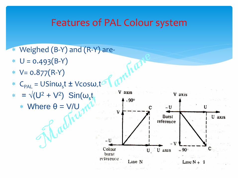
Weighed (B-Y) and (R-Y) are-
U = 0.493(B-Y)
V= 0.877(R-Y)
CPAL = USinωst ± Vcosωst
= √(U2 + V2) Sin(ωst ± θ)
Where θ = V/U
Features of PAL Colour system
+
PAL receiver requires three types of carrier.
Subcarrier at 0º phase to detect U signal
Subcarrier at +90º phase at every second line for V.
Subcarrier at -90º phase at every second line for V.
V demodulator must be switched at half horizontal line frequency rate.
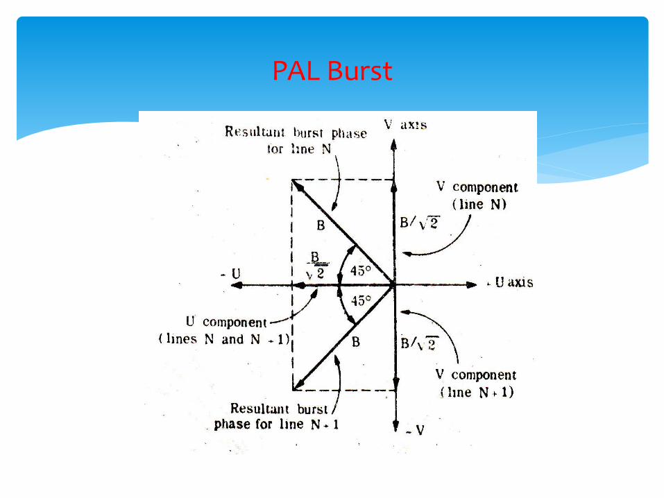
Hence PAL Colour burst has two components.
1. -(B-Y) (same as NTSC), but of amplitude 1/√2 of NTSC burst.
2. (R-Y) component which is reversed in phase from line to line, amplitude same as –(B-Y)
PAL Burst
PAL Burst
Resultant burst swings ± 45º about –(B-Y) axis from line to line.
Sign of (R-Y) burst always same as that of (R-Y).
Hence called swinging burst.
PAL Burst
Multiple path transmission results in phase errors.
Called differential phase error.
Changes hue in reproduced picture.
PAL has built-in protection against phase errors.
Provided picture content almost remains same from line to line.
Cancellation of phase errors
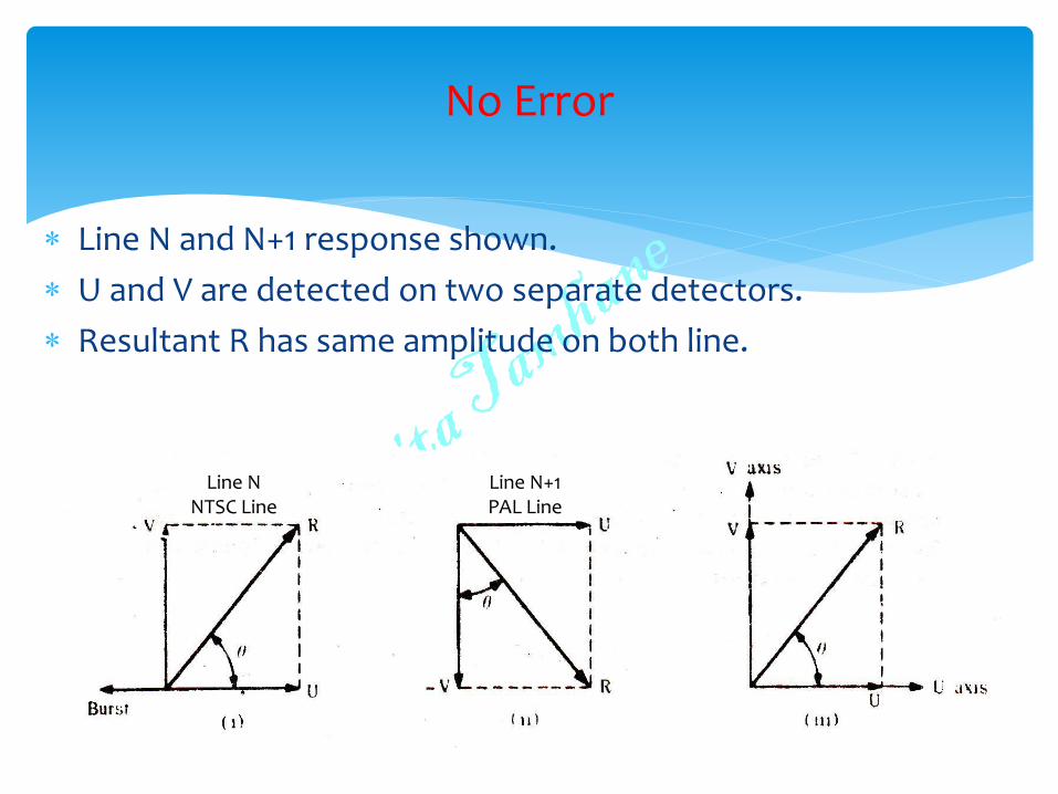
Line N and N+1 response shown.
U and V are detected on two separate detectors.
Resultant R has same amplitude on both line.
No Error
Line N NTSC Line
Line N+1 PAL Line
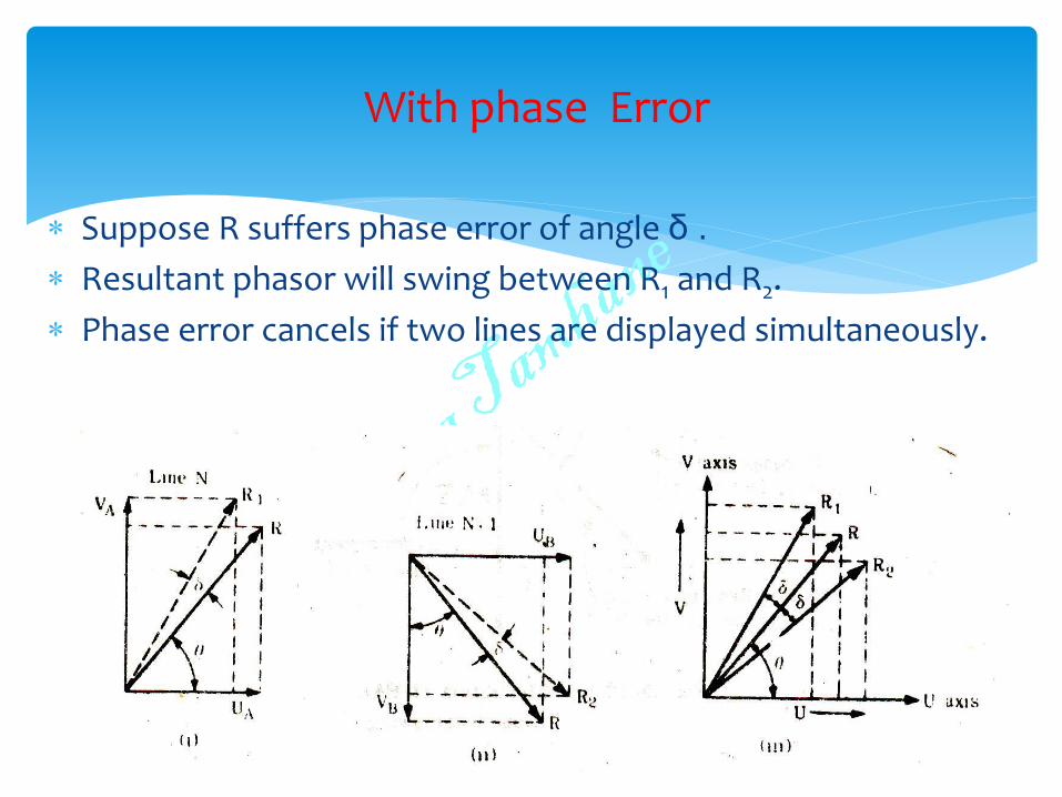
Suppose R suffers phase error of angle δ .
Resultant phasor will swing between R1 and R2.
Phase error cancels if two lines are displayed simultaneously.
With phase Error
Practically, two lines are displayed in sequence.
Colours reproduced by two successive lines will be slightly on either side of actual hue.
Since lines are scanned at very fast rate, eye perceives a colour that lie between two colours reproduced by R1 and R2.
Hence colour viewed will be more or less the desired hue.
PAL superior to NTSC in this front.
Cancellation of phase errors
Small errors not visible to eye.
Beyond a limit, eye starts to see the error in alternate lines.
Remedy – Delay line employed to do the averaging of alternate line colour information first then present the colour to viewer.
Hence called Delay line PAL or PAL-D
PAL - D
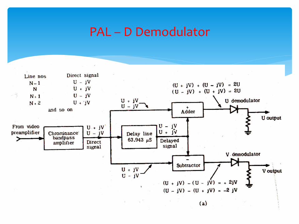
PAL – D Demodulator
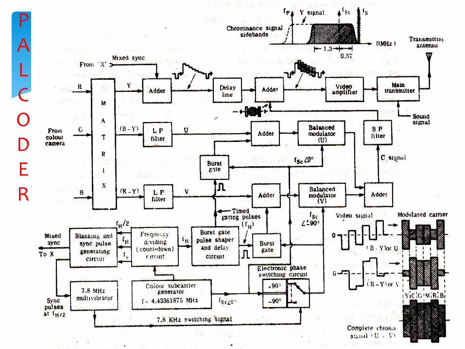
PAL CODER
PAL DECOER
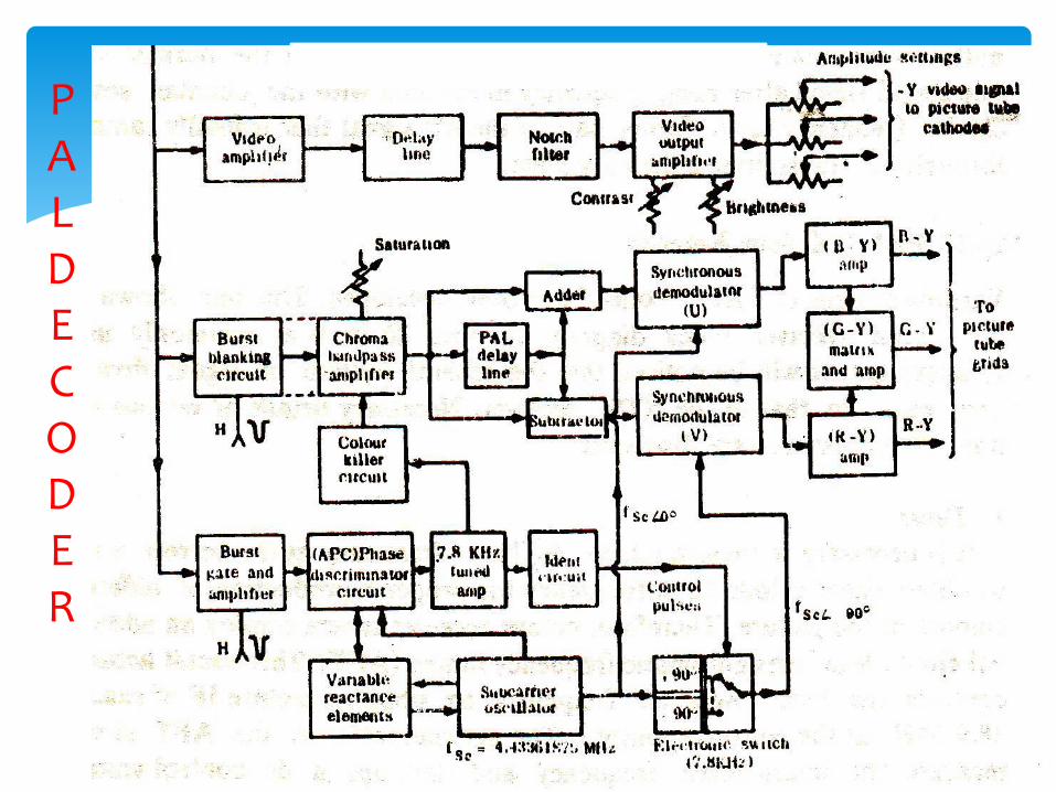
PAL DECODER
PAL-D removes phase errors and Differential phase error problem .
Manual hue control not needed..
BUT..
Delay line technique of reception results in reduction in vertical resolution of chrominance signal.
More complicated and expensive due to delay lines, adding, subtracting…
Receiver cost higher.
Merits and Demerits of PAL
Earlier – 819 lines system with B/W of 14MHz.
NOW –
625 lines per frame.
25 frames per second.
50 fields per second
Line frequency – 15625HZ
Field frequency – 50Hz
Video B/W – 6MHz
Channel B/W – 8MHz
Picture – FM
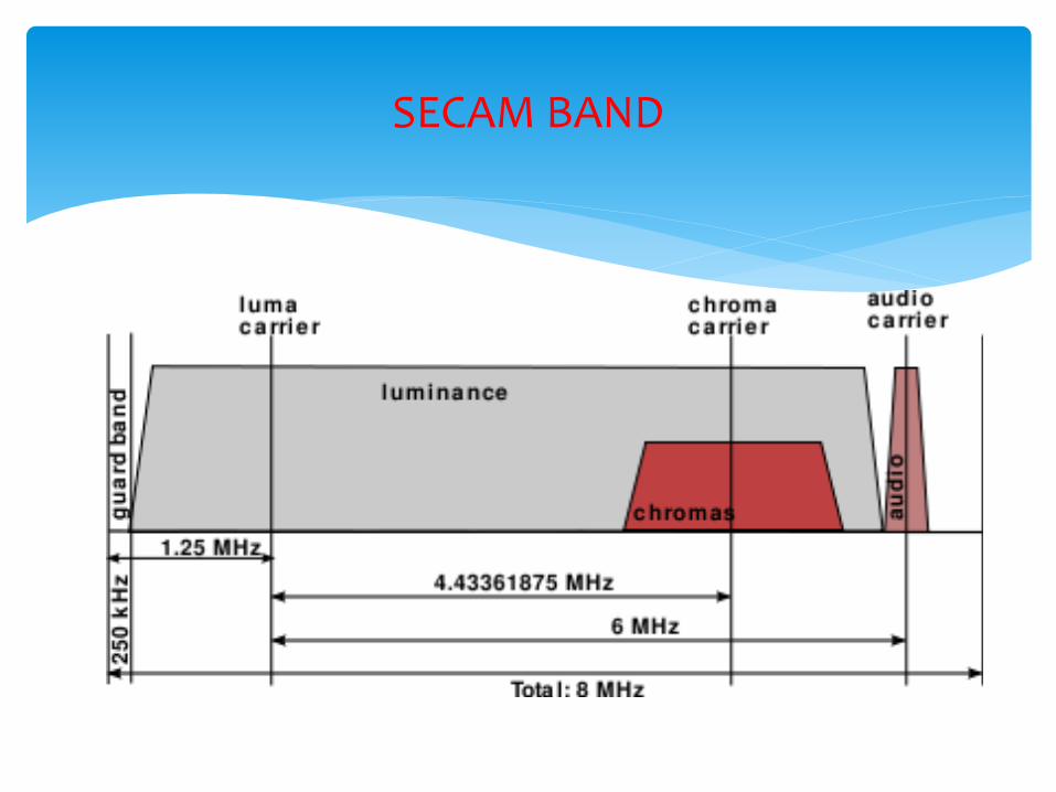
SECAM System
Sound carrier 5.5MHz away from Picture carrier.
Colour Subcarrier ---4.4375MHz away from Picture carrier.
Y signal same as NTSC/PAL.
Weighing factor –
IDRI = -1.9(R-Y)
IDBI = 1.5(B-Y)
SECAM System
French “Sequential a Memoire”.
Only one of two colour difference signal transmitted at a time.
(R-Y) transmitted in one line and (B-Y) in next line.
Sequence repeated for full raster.
Due to odd number of lines, (R-Y) and (B-Y) alternate each picture.
Subcarrier is frequency modulated by colour difference signal before transmission.
Magnitude of frequency deviation represents colour saturation and rate of deviation its hue.
SECAM System
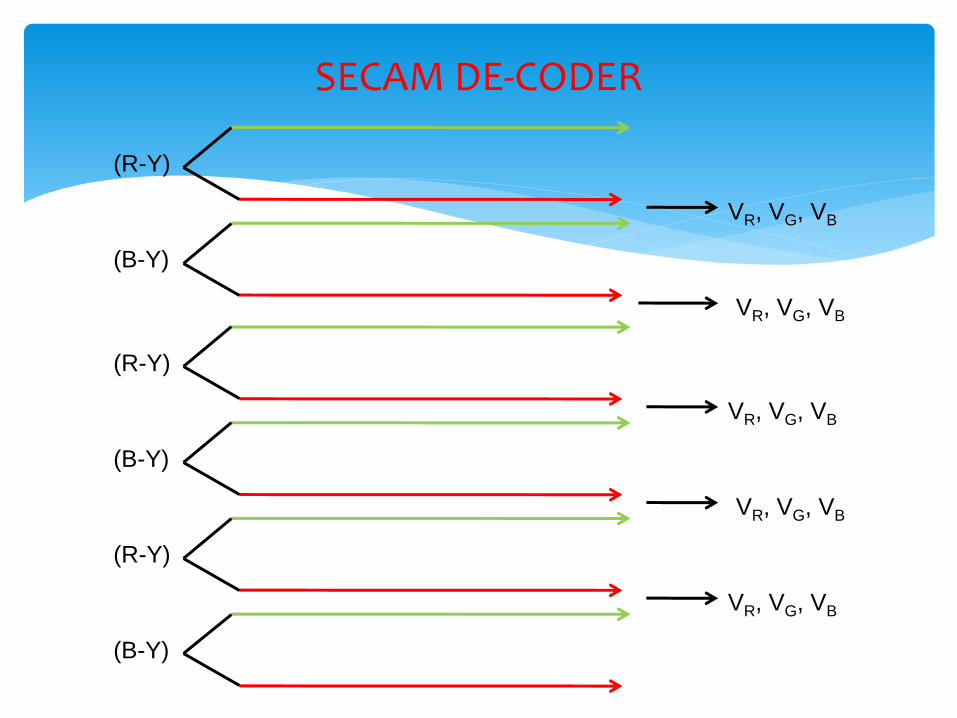
Ultrasonic delay line of 64µs used as one line memory device.
Produces decoded output of both colour difference signal simultaneously.
Modulated signals routed to their correct demodulators by an electronic switch operating at line frequency.
Switch driven by Bistable Multivibrator.
Determination of proper sequence of colour lines in each field is accomplished by Identification pulse .
Ident generated and transmitted during vertical blanking interval.
Principle of SECAM SYSTEM
FM for colour.
Phase distortions in transmission path will not change hue of picture area as two carriers are at same phase..
Limiter to remove amplitude variation.
Subcarrier for (R-Y) = 282fH = 4.40625MHz
Subcarrier for (B-Y) = 272fH = 4.250MHZ
Suppresses dot pattern interference on B/W TV.
Modulation of Subcarrier
Colour difference signals band limited to 1.5MHZ and pre-emphasised.
Linear deviation for (R-Y) = 280DR KHz
MAX DEVIATION: 500KHZ and 350KHZ as below.
+(R-Y) = -500KHz
-(R-Y) = +350KHz
Linear deviation for (B-Y) = 230DB KHz
MAX DEVIATION: 500KHZ and 350KHZ as below.
+(B-Y) = +500KHz
-(B-Y) = -350KHz
Modulation of Subcarrier
It is necessary for receiver to determine which line is being transmitted.
Ident pulses are generated during Vertical blanking pulses.
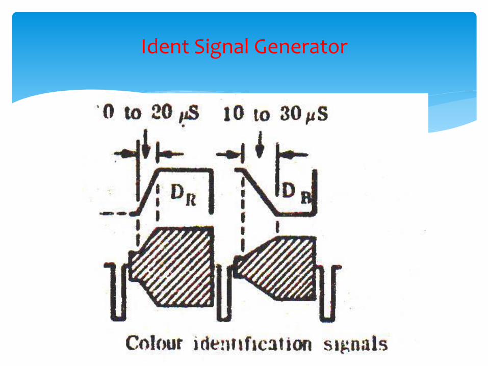
Ident signal is carrier duly modulated by a saw-tooth signal.
Sawtooth signal is positive going for DR and negative going for DB.
At receiver, generate positive and negative control signal after detection.
Regulates instant and sequence of switching.
Ident Signal Generator
Ident Signal Generator
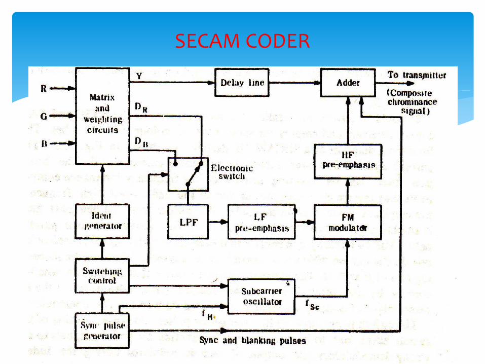
SECAM CODER
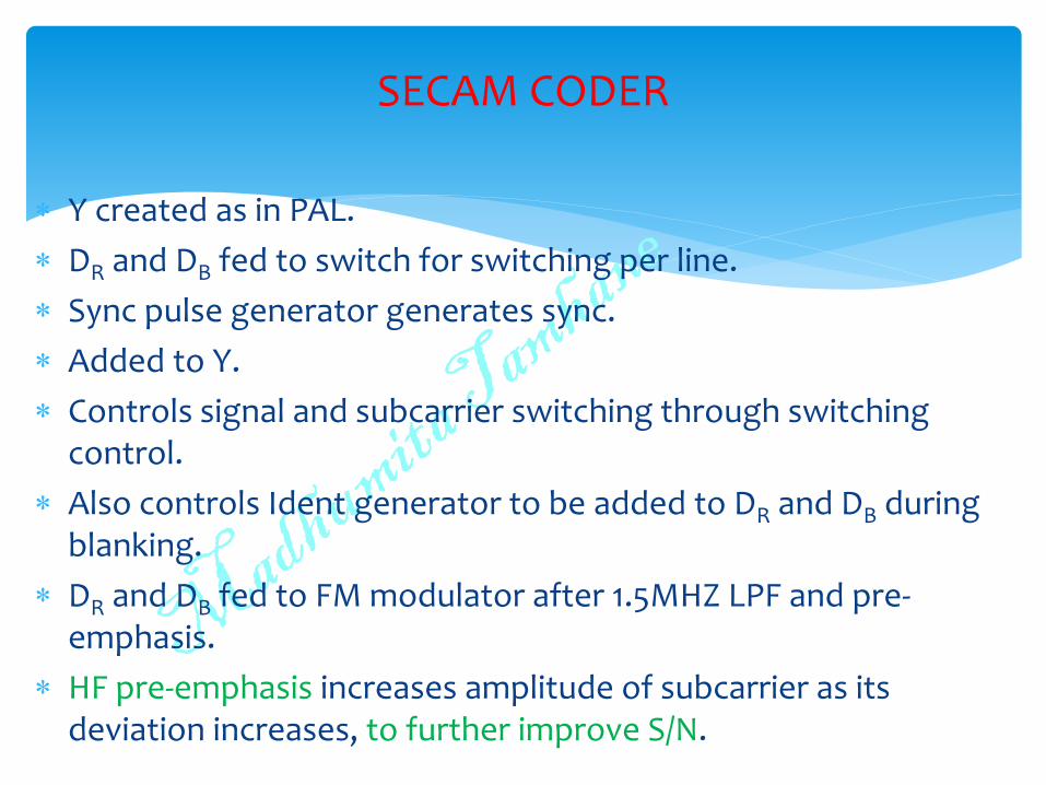
Y created as in PAL.
DR and DB fed to switch for switching per line.
Sync pulse generator generates sync.
Added to Y.
Controls signal and subcarrier switching through switching control.
Also controls Ident generator to be added to DR and DB during blanking.
DR and DB fed to FM modulator after 1.5MHZ LPF and pre-emphasis.
HF pre-emphasis increases amplitude of subcarrier as its deviation increases, to further improve S/N.
SECAM CODER
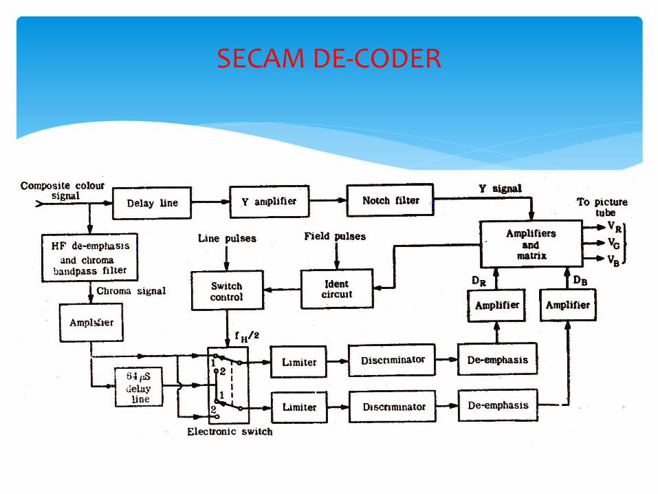
SECAM DE-CODER
SECAM DE-CODER
(R-Y)
(B-Y)
VR, VG, VB
(R-Y)
(B-Y)
VR, VG, VB
VR, VG, VB
(R-Y)
(B-Y)
VR, VG, VB
VR, VG, VB
By Japan Broadcast Company NHK.
Offers wide screen format.
Does not show scan lines even from close.
Has twice vertical and horizontal resolution.
Improves colour rendition.
Stereophonic sound.
1125/60 HDTV comparable to 35mm theatre film.
22GHz band for HDTV direct broadcast to TV.
HDTV
Three parts:
Generating equipment Camera, VCR
Transmitters and links – microware, satellite.
Large screen TV receiver, projection TV
Highly sensitive equipments developed for each of above.
HDTV
Aspect ratio 19:9.
Gives channel B/W = 26.7MHz.
60Hz field preferred to reduce flicker.
HDTV
Top Related